

Page 1
www.wackergroup.com
0171956 002
0108
Laser Level
Nivel láser
Niveau électronique
HAL 300
HAL 300-230V
OPERATOR’S MANUAL
Manual de Operación
Notice d’Emploi
0171956
Page 2

Page 3

Wacker HAL 300 Table of Contents
1. Foreword EN-2
2. Safety Information EN-3
2.1 Operating Safety ............................................................................ EN-4
2.2 Service Safety ................................................................................ EN-4
2.3 Label Locations .............................................................................. EN-5
2.4 Safety and Operating Labels .......................................................... EN-5
3. Operation EN-6
3.1 Set-up and Operation Locations ..................................................... EN-6
3.2 Application ...................................................................................... EN-8
3.3 Calibration ...................................................................................... EN-8
3.4 Horizontal Setup and Operation ..................................................... EN-8
3.5 H.I. (Height of Instrument) Alert ...................................................... EN-9
3.6 Rotation Speed ............................................................................. EN-10
3.7 Slope Match ................................................................................. EN-11
3.8 Power ........................................................................................... EN-12
3.9 Laser Detector .............................................................................. EN-14
3.10 Other Accessories ........................................................................ EN-16
4. Maintenance EN-17
4.1 Checking and Adjusting ................................................................ EN-17
4.2 Calibration Overview .................................................................... EN-18
4.3 Checking and Calibrating X and Y Axes ...................................... EN-20
4.4 Cone Error Checking .................................................................... EN-22
4.5 Care and Handling ....................................................................... EN-23
4.6 Troubleshooting ............................................................................ EN-23
5. Technical Data EN-25
5.1 HAL 300 Laser Level .................................................................... EN-25
5.2 Laser Detector .............................................................................. EN-26
wc_bo0171956en_001TOC.fm EN-1
Page 4

1 Foreword
Foreword
This manual provides information and procedures to safely operate
and maintain this Wacker model. For your own safety and protection
from injury, carefully read, understand and observe the safety
instructions described in this manual.
Keep this manual or a copy of it with the machine. If you lose this
manual or need an additional copy, please contact Wacker
Corporation. This machine is built with user safety in mind; however,
it can present hazards if improperly operated and serviced. Follow
operating instructions carefully! If you have questions about operating
or servicing this equipment, please contact Wacker Corporation.
The information contained in this manual was based on machines in
production at the time of publication. Wacker Corporation reserves the
right to change any portion of this information without notice.
All rights, especially copying and distribution rights, are reserved.
Copyright 2007 by Wacker Corporation.
No part of this publication may be reproduced in any form or by any
means, electronic or mechanical, including photocopying, without
express written permission from Wacker Corporation.
Any type of reproduction or distribution not authorized by Wacker
Corporation represents an infringement of valid copyrights and will be
prosecuted. We expressly reserve the right to make technical
modifications, even without due notice, which aim at improving our
machines or their safety standards.
EN-2
Page 5
Wacker HAL 300 Safety Information
2. Safety Information
This manual contains DANGER, WARNING, CAUTION, NOTICE and
NOTE callouts which must be followed to reduce the possibility of
personal injury, damage to the equipment, or improper service.
This is the safety alert symbol. It is used to alert you to potential
personal injury hazards. Obey all safety messages that follow this
symbol to avoid possible injury or death.
DANGER indicates a hazardous situation which, if not avoided, will
result in death or serious injury.
DANGER
WARNING
CAUTION
WARNING indicates a hazardous situation which, if not avoided, could
result in death or serious injury.
CAUTION indicates a hazardous situation which, if not avoided, could
result in minor or moderate injury.
NOTICE: Used without the safety alert symbol, NOTICE indicates a
hazardous situation which, if not avoided, could result in property
damage.
Note: Contains additional information important to a procedure.
wc_si000242gb.fm EN-3
Page 6

Wacker HAL 300 Safety Information
2.1 Operating Safety
2.1.1 ALWAYS read, understand, and follow procedures in the Operator’s
Manual before attempting to operate the machine.
2.1.2 ALWAYS store the machine properly when it is not being used. The
machine should be stored in a clean, dry location out of the reach of
children.
2.1.3 ALWAYS operate the machine with all safety devices and guards in
place and in working order.
Possible eye injury! When the laser is not rotating, do not stare into the
pointing beam.
CAUTION
2.2 Service Safety
A poorly maintained machine can become a safety hazard! In order
for the machine to operate safely and properly over a long period of
time, periodic maintenance and occasional repairs are necessary.
WARNING
2.2.1 All adjustments and repairs MUST be completed before operation.
NEVER operate the machine with a known problem or deficiency! All
repairs and adjustments should be completed by a qualified
technician.
2.2.2 DO NOT modify the machine without the express written approval of
the manufacturer.
2.2.3 ALWAYS keep the machine clean and labels legible. Replace all
missing and hard-to-read labels. Labels provide important operating
instructions and warn of dangers and hazards.
2.2.4 ALWAYS do periodic maintenance as recommended in the Operator’s
Manual.
wc_si000242gb.fm EN-4
Page 7
Wacker HAL 300 Safety Information
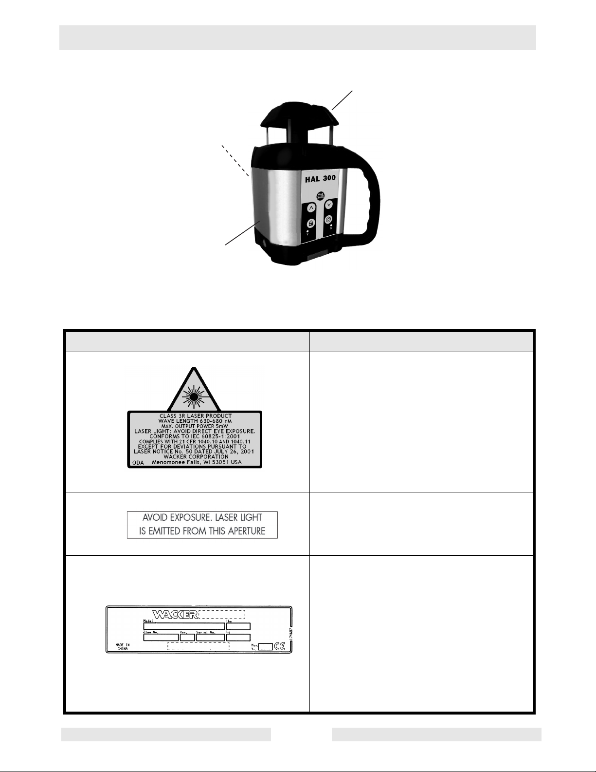
2.3 Label Locations
B
A
C
wc_gr004597
2.4 Safety and Operating Labels
Ref. Label Meaning
A This instrument is a Class 3R laser,
manufactured to comply with the
international rules of safety IEC 60825-1,
2001. Although the power of the emission
of the beam is less than 5 mW in Class
3R, the following cautions are
recommended:
• Do not stare directly at the beam.
• Do not set up the laser at eye level.
B Avoid exposure. Laser light is emitted
from this aperture.
C A nameplate listing the model number,
item number, revision number, and serial
number is attached to each unit. Please
record the information found on this plate
so it will be available should the
nameplate become lost or damaged.
When ordering parts or requesting
service information, you will always be
asked to specify the model number, item
number, revision number, and serial
number of the unit.
wc_si000242gb.fm EN-5
Page 8

Wacker HAL 300 Operation
3. Operation
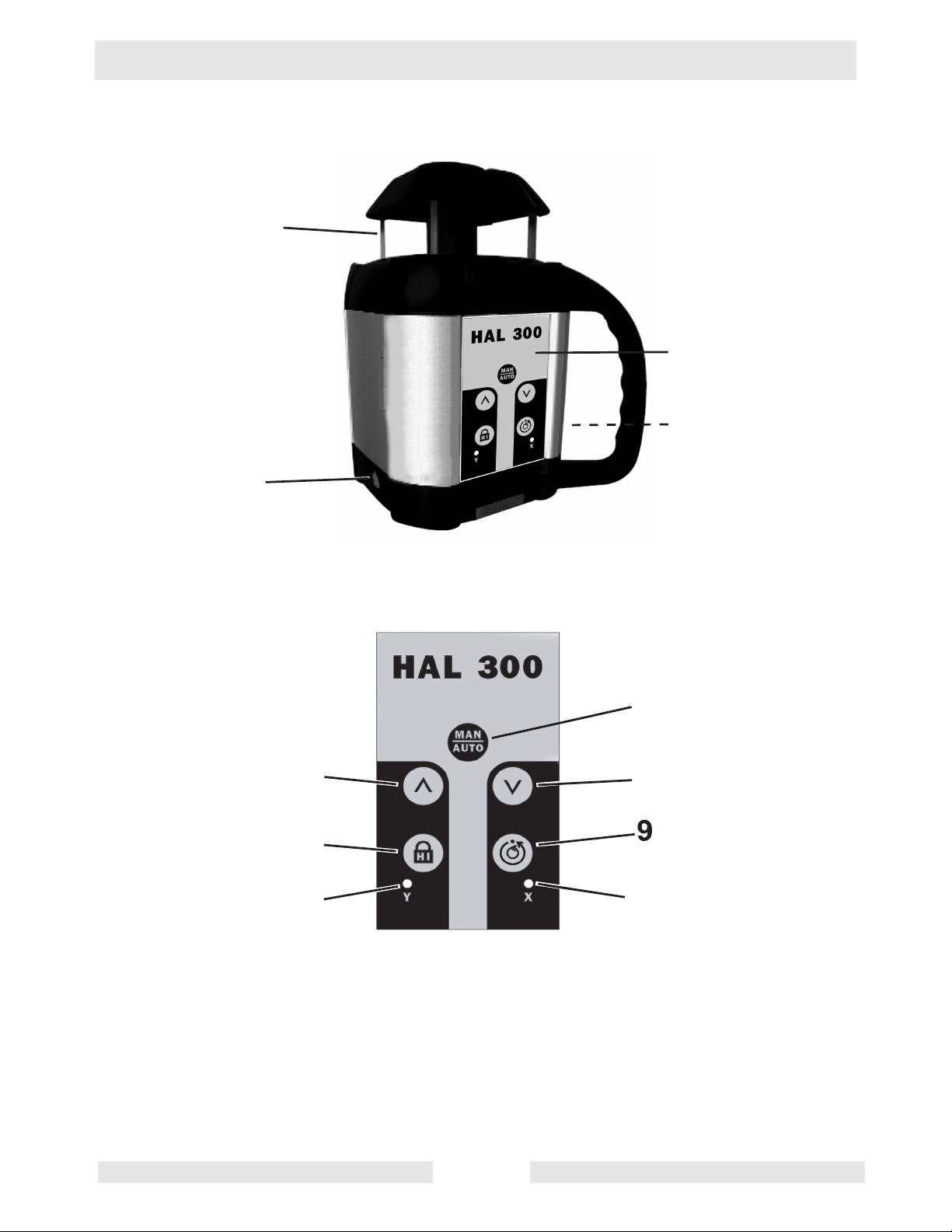
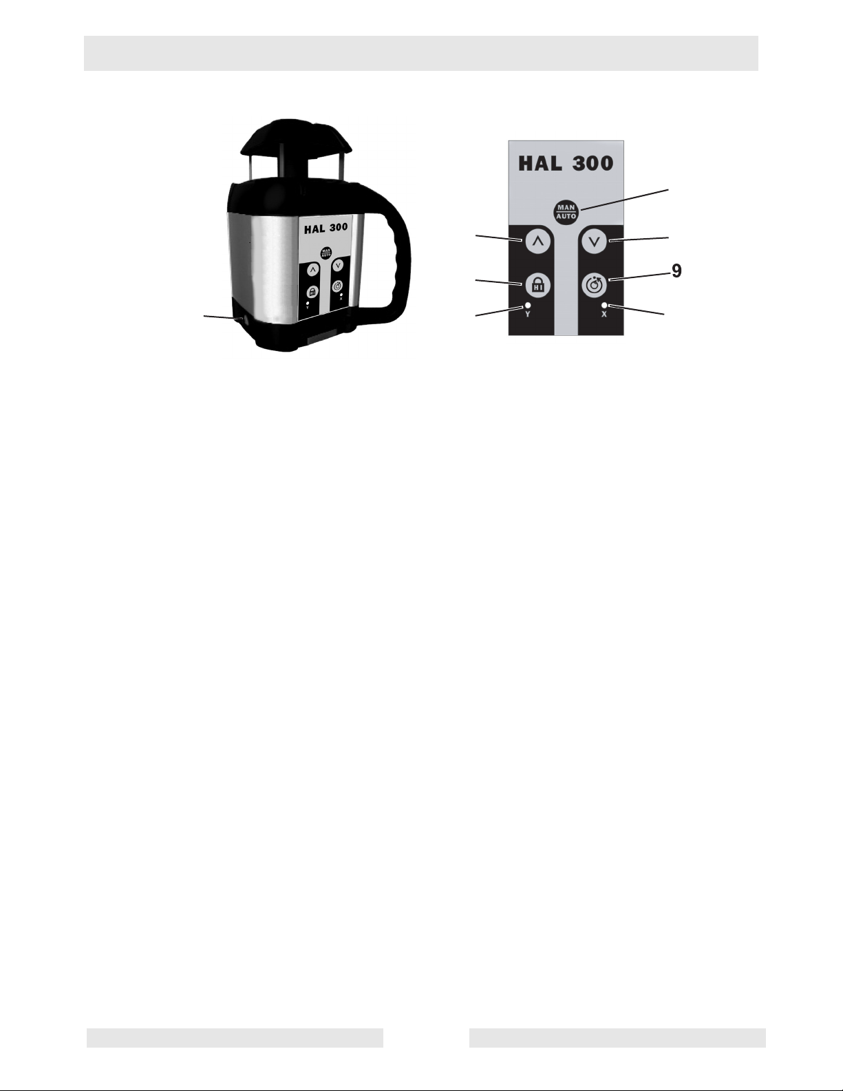
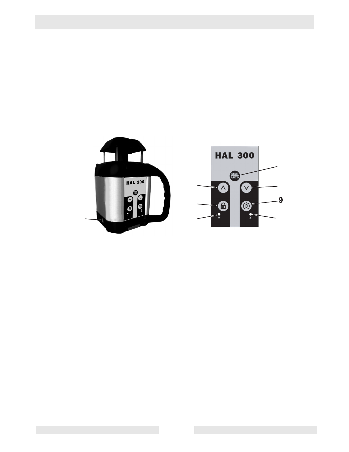
3.1 Set-up and Operation Locations
See Graphic: wc_gr004578
Ref. Description Ref. Description
1 Rotating laser beam (head
enclosed in glass lighthouse)
2 Charger jack 8 H.I. (Height of Instrument) Alert
3 ON / OFF key 9 Rotation speed adjustment
4 Laser keypad 10 LED for H.I. Alert
5 Match slope
Beam up in calibration mode
6 Match slope
Beam down in calibration mode
Italics correspond to indicators and keys used in calibration mode.
7 MAN/AUTO key
Y axis calibration
11 LED for manual mode
X axis calibration
wc_tx000803gb.fm EN-6
Page 9
Wacker HAL 300 Operation
1
4
2
3
5
8
10
7
6
11
wc_gr004578
wc_tx000803gb.fm EN-7
Page 10

Wacker HAL 300 Operation
3.2 Application
This Wacker laser transmitter is simple to use, yet it has several
advanced features:
• Automatic self-leveling in horizontal
• Visible laser beam
• Easy electronic calibration
• Match slope in X and Y axes
3.3 Calibration
It is important to check your laser for proper calibration. The laser is a precision instrument and it is important that you keep it calibrated and in proper
condition. The accuracy of your work is completely your responsibility and you
should check your instrument before beginning each job, and especially after
the instrument has taken a sharp jolt or been dropped, or when temperature
changes greater than 50 degrees F (28 degrees C) have occurred. See “Maintenance” for calibration procedures.
3.4 Horizontal Setup and Operation
See Graphic: wc_gr004599
3.4.1 The HAL 300 laser can be used on a wall mount; directly on a solid,
stable surface; or on a standard 5/8-11 tripod. The laser has a wide
self-leveling range; however, if the laser is set up outside of leveling
range, the beam will continue to blink and rotation will not start.
3.4.2 Press the ON/OFF switch (3) to turn the laser on. The laser will perform
a self-test when turned on. The beam will blink while the laser is selfleveling. After it has leveled, the head will start to rotate.
3.4.3 Select the H.I. (Height of Instrument) alert by pressing the H.I. Alert
Function key (8). The H.I. alert function will be active 30 seconds after
the HAL 300 has finished its self-leveling.
3.4.4 There are three rotation speeds: 0, 90, and 600 rpm (the default
speed). To change to 90 rpm, press the rotation speed key (9). Press
the key again to stop the rotation.
3.4.5 To turn the laser off, press the ON/OFF switch.
wc_tx000803gb.fm EN-8
Page 11
Wacker HAL 300 Operation
7
3
10
3.5 H.I. (Height of Instrument) Alert
See Graphic: wc_gr004599
3.5.1 The H.I. Alert feature stops the laser automatically if the laser is
disturbed, preventing inaccurate readings. It functions only when
selected.
3.5.2 To activate this safeguard feature, press the H.I. Alert Function key (8)
after turning the laser on. The H.I. Alert Indicator LED (10) will blink
rapidly while the laser is self-leveling.
5
6
8
11
wc_gr004599
3.5.3 About 30 seconds after the head starts to rotate, the LED will blink
slowly, indicating the H.I. Alert is activated.
3.5.4 If the laser is disturbed while in H.I. Alert mode, the head will stop
rotating, the beam will turn off, and the LED indicator will stay on
continuously.
3.5.5 To reset the laser after an H.I. Alert, turn the laser off and turn it on
again. Check to see if the beam elevation has changed from its original
benchmark position.
3.5.6 The laser is no longer in H.I. Alert mode. Press the H.I. Alert Function
key to return to H.I. Alert.
3.5.7 While using the laser, check periodically to make sure that it has not
been moved and that your settings are still accurate.
wc_tx000803gb.fm EN-9
Page 12
Wacker HAL 300 Operation
3.6 Rotation Speed
See Graphic: wc_gr004599
3.6.1 There are 3 rotation speeds: 0, 90 and 600 rpm (the default speed). To
change to 90 rpm, press the Rotation Speed key (9). Press again to
stop rotation.
3.6.2 The laser beam is more visible at the slower speed. The faster speed
(600 rpm) is required for many machine control receiver applications.
7
5
6
8
3
10
wc_gr004599
11
wc_tx000803gb.fm EN-10
Page 13

Wacker HAL 300 Operation
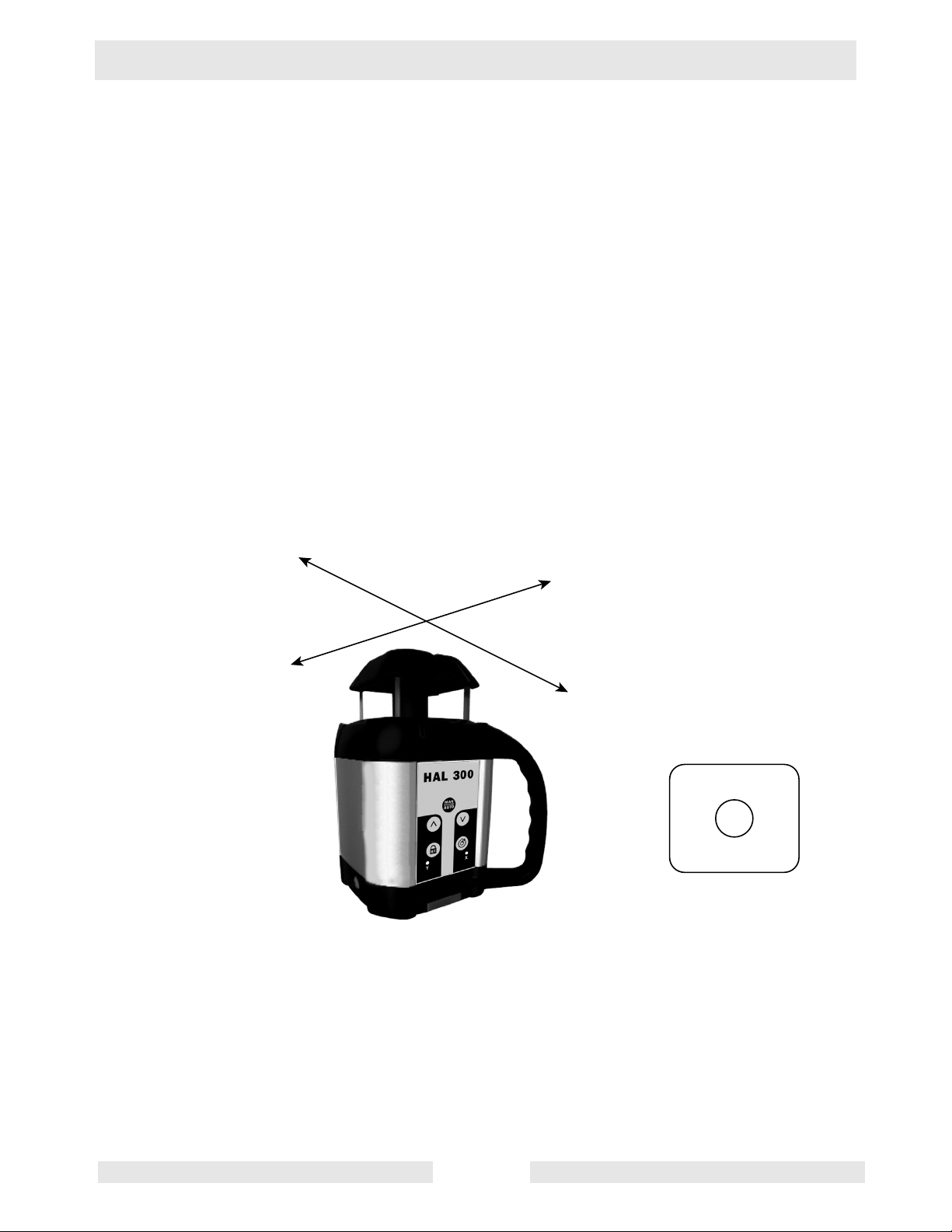
3.7 Slope Match
See Graphic: wc_gr004599
3.7.1 The laser can be used to match manual slope on both X and Y axes.
Two modes are available:
• Complete manual mode: X and Y axis will be both manual
• Semi-automatic mode: Y in automatic / X in manual
Semi-automatic mode
3.7.1 Set the laser over a start point.
3.7.2 Turn the laser so that the side of the laser with the handle, +X, faces
the direction of the slope (and -X faces away; see axis direction in
“Maintenance”). Use the sighting groove on the top of the housing to
roughly align the X axis of the laser to the second point.
3.7.3 After turning the laser on and allowing it to self-level, hold the MAN/
AUTO key (7) for a few seconds until the X LED (11) is lit continually.
The laser is now in manual mode in X axis and automatic self-leveling
mode in Y axis.
3.7.4 Press ^ (5) on the keypad to match a positive slope in X and v (6) to
match a negative slope; the Y axis will stay level.
3.7.5 Press twice on the MAN/AUTO key to return to the automatic mode.
Manual Mode
3.7.1 Set the laser over a start point.
3.7.2 Turn the laser so that the side of the laser with the handle, +X, faces
the direction of the slope (and -X' faces away; see axis direction in
“Maintenance”). Use the sighting groove on the top of the housing to
roughly align the X axis of the laser to the second point.
3.7.3 After turning the laser on and allowing it to self-level, hold the MAN/
AUTO key (7). The X LED (11) will blink, indicating the laser is now in
manual mode and can match slope in the in X axis.
3.7.4 Press ^ (5) on the keypad to match a positive slope in X and v (6) to
match a negative slope.
3.7.5 To switch to the Y axis, press the H.I. key (8). Both LEDs will blink,
indicating you’re in manual mode and can match slope in the Y axis.
3.7.6 Press ^ (5) on the keypad to match a positive slope in Y and v (6) to
match a negative slope. Press on the MAN/AUTO key to return to the
automatic mode.
Note: The Y axis grade will be at a 90° angle from the X axis grade
output.
In manual mode, the beam rotates even if the laser is not leveled. The
H.I. Alert function is not available when the unit is in manual mode.
wc_tx000803gb.fm EN-11
Page 14

Wacker HAL 300 Operation
3.8 Power
Laser battery
The laser has a NiCad rechargeable battery that should be charged for
15 hours before first use.
Charging the battery
3.8.1 Remove the charging connector cover on the side of the laser. Insert
the charger plug and fully engage the threads.
3.8.2 Plug the charger into an electrical outlet (110 volts or 230 volts,
depending on charger and country).
3.8.3 Charge for 15 hours. When the charger is plugged in, a red light will
illuminate on the charger.
The laser can be charged while working. If electricity is available on the
job site, simply plug in the charger and keep working.
For optimum life of the battery, it is recommended to charge the battery
after fully discharged. To assure battery life, do not charge over 20
hours.
Note: Although the laser is waterproof, do not charge it while it is in
water or submerged.
wc_tx000803gb.fm EN-12
Page 15

Wacker HAL 300 Operation
Notes
wc_tx000803gb.fm EN-13
Page 16

Wacker HAL 300 Operation
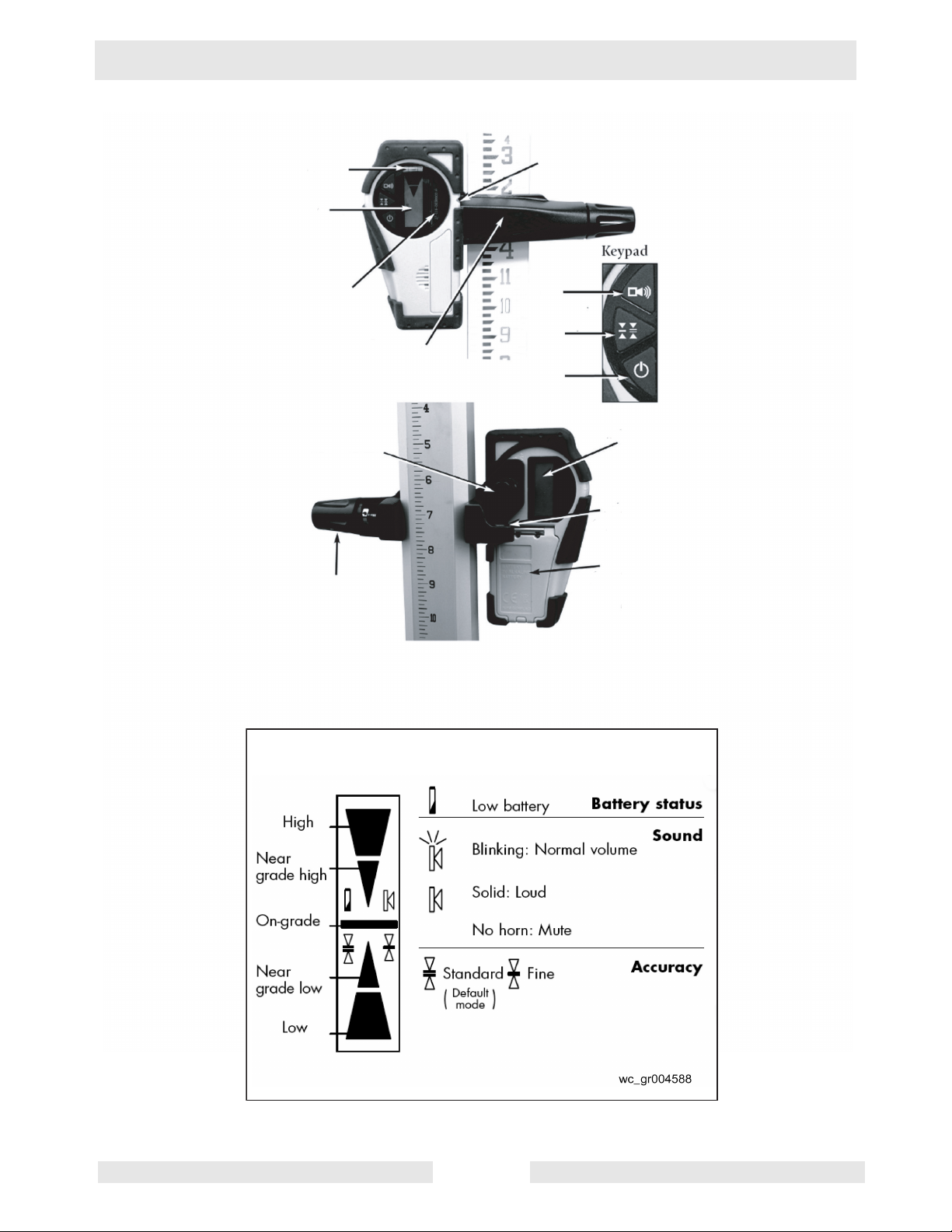
3.9 Laser Detector
Your laser transmitter is provided with a laser detector to be used with
a grade rod or handheld applications. Detectors are recommended
when it is difficult to see the laser beam, such as outdoors or in bright
light.
See graphic: wc_gr004586
Ref. Description Ref. Description
1 Level vial 8 ON / OFF
2 LCD screen (front) 9 Turn to attach clamp to detector
3 Detection window 10 Turn to tighten or remove clamp
from grade rod
4 Rod clamp 11 9V battery compartment
(Follow polarity indications inside)
5 On-grade alignment notch 12 Bubble vial to plumb rod
6 Choice of sound level 13 LCD screen (rear)
7 Choice of accuracy
wc_tx000803gb.fm EN-14
Page 17

Wacker HAL 300 Operation
1
2
10
3
9
5
6
7
4
8
13
12
11
LCD Display
wc_gr004586
wc_tx000803gb.fm EN-15
Page 18

Wacker HAL 300 Operation
See graphic: wc_gr004586 and wc_gr004588
Using the detector:
3.9.1 Press the ON / OFF key (8) to turn on the detector.
3.9.2 Press the middle key (7) to select the accuracy (deadband).
3.9.3 Press the top key (6) to select the sound level.
3.9.4 Turn the detection window (3) towards the laser beam, and move the
detector up or down according to the information given on the LCD
screen (2). There are five channels of information, or grade indicators.
3.9.5 A down arrow indicates that you must move the detector down to reach
the laser reference; and up arrow indicates that you must move it up.
When a horizontal line appears on the display, the detector is at the
same level as the laser beam.
3.9.6 Press the ON / OFF key to turn the detector off. It will automatically
sound a warning beep and shut off after 10 minutes if not used.
3.9.7 Keep the detection window clean, using a soft cloth and glass cleaner.
3.10 Other Accessories
Contact your Wacker dealer for information about available
accessories.
wc_tx000803gb.fm EN-16
Page 19
Wacker HAL 300 Maintenance
4. Maintenance
4.1 Checking and Adjusting
THIS SECTION IS VERY IMPORTANT: Here are a few simple
instructions to check your laser for calibration. The laser is a precision
instrument and it is important that you keep it calibrated and in proper
condition. The accuracy of your work is completely your responsibility
and you should check your instrument before beginning each job, and
especially after the instrument has taken a sharp jolt or been dropped,
or when temperature changes greater than 50 degrees F (28 degrees
C) have occurred.
See graphic: wc_gr004600
The laser has two horizontal axes: X and Y, as indicated on the top of
the laser.
+Y
+X
-X
-Y
+Y
-X
-Y
wc_gr004600
Each end of each axis must be checked for calibration. If needed, the
axis can be calibrated, carefully following the instructions. You can
also take the laser to a Wacker service center for calibration.
Front of laser
+X
wc_tx000806gb.fm EN-17
Page 20

Wacker HAL 300 Maintenance
Check and calibrate in this order:
4.1.1 Check both sides of X axis.
• If X is within spec, proceed to check both sides of Y
• If X needs calibration, calibrate X
4.1.2 Check both sides of Y axis.
• If Y is within spec, proceed to final X to Y check
• If Y needs calibration, calibrate Y; proceed to X to Y check
4.1.3 Final X to Y check: compare +X, -X, +Y, -Y.
4.2 Calibration Overview
See graphic: wc_gr004601
4.2.1 Calibration is electronic, and is accomplished by using the optional
detector/remote control or the optional small remote control (preferred
methods).
4.2.2 If you do not have a remote, the laser keypad may also be used. This
method will take longer due to the laser making self-adjustments
during movement. Be very careful not to jar or move the laser when
pushing the laser keys, or your calibration will not be accurate.
4.2.3 When in calibration mode, the X or Y LED on the laser keypad should
blink slowly. When the laser is self-leveling or making an adjustment,
the LED will blink rapidly. Wait until the LED blinks slowly again before
proceeding.
Moving the beam to calibrate:
4.2.1 IMPORTANT: When pressing an arrow key to move the beam for
calibration, use short, rapid clicks. Do not hold the key down. One click
will move the beam a very small amount (1/32" at 150' or 1mm at
100m). After pressing the key, the LED will blink rapidly as the laser
reacts. Wait until the LED returns to a slow blink to proceed.
4.2.2 If the +X or +Y axis is toward the wall with the marks, use the ^ key (5)
to raise beam, and the v key (6) to lower beam. If the -X or -Y axis is
toward the wall, it's the opposite: use the v key to raise the beam and
the ^ key to lower the beam.
wc_tx000806gb.fm EN-18
Page 21

Wacker HAL 300 Maintenance
7
5
8
10
Keys used on optional detector / remote control
when laser is in calibration mode
Use arrows to move
beam up or down
to reach proper
calibration.
If using a remote control,
keys with the same symbols
perform the same functions.
6
11
Change from X to Y axis
Save calibration
Starts rotation
(in calibration mode)
wc_gr004601
wc_tx000806gb.fm EN-19
Page 22

Wacker HAL 300 Maintenance
4.3 Checking and Calibrating X and Y Axes
4.3.1 Place the laser on a flat surface or tripod 100 ft. (30 m) away from a
wall. If too bright to see the beam, use a detector with a pole or grade
rod.
Position so that -X is facing the wall (this is the side of the laser with
the On/Off key).
Use the sighting groove on top of the instrument for alignment.
4.3.2 Hold ROTATION key. While holding, momentarily press the ON key.
Look for
• Y LED flashes, then X LED flashes. Release rotation key.
• X LED will blink rapidly, indicating leveling. When the LED blinks
slowly, the laser is ready to verify X axis calibration.
4.3.3 To rotate laser beam: Press SCAN key on the remote (or press the
rotation key on the laser keypad).
4.3.4 Check X calibration:
4.3.4.1 With detector, mark center of the beam (-X).
4.3.4.2 Rotate laser 180° so +X is facing wall or pole.
4.3.4.3 With detector, mark center of the beam (+X).
4.3.4.4 At 100 ft., the marks should be no more than 1/4" apart. (At
30 m, no more than 6 mm apart.)
If the marks are close enough, X axis is within calibration; proceed to
Step 6.
4.3.5 If the marks are not close enough, the laser must be calibrated to bring
the beam to the center of the two X marks. Use the (^) or (v) ARROW
keys on the remote (preferred) or laser keypad to move beam up or
down to the center.
Note: With the arrow keys, make small inputs: one click, two clicks,
three clicks, etc. Do NOT hold key down.
4.3.6 After calibrating X, check Y. Rotate laser 90° degrees so that -Y is
facing the wall (this is the side of the laser with the keypad).
4.3.7 Select the Y axis by pressing the double arrow key ( >>l ) on the remote
(or the HI key on the laser keypad).
Look for
• Y LED blinking rapidly, indicating leveling. When the LED blinks
slowly, the laser is ready to verify Y axis calibration.
4.3.8 Check Y calibration:
4.3.8.1 With detector, mark center of the beam (-Y).
4.3.8.2 Rotate laser 180° so +X is facing wall or pole.
wc_tx000806gb.fm EN-20
Page 23

Wacker HAL 300 Maintenance
4.3.8.3 With detector, mark center of the beam (+Y).
4.3.8.4 At 100 ft., the marks should be no more than 1/4" apart. (At
30 m, no more than 6 mm apart.) If the marks are close
enough, Y axis is within calibration; proceed to Step 4.3.10.
4.3.9 If the marks are not close enough, the laser must be calibrated to bring
the beam to the center of the two Y marks. Use the (^) or (v) ARROW
keys on the remote or laser keypad to move beam up or down to the
center.
4.3.10 Final X to Y check: compare X to Y axes to be sure that your adjusted
calibration is within specification of ± 1/8"at 100 ft. (± 3 mm at 30 m).
Turn the laser 90° each time; the marks for +X, -Y, -X, +Y should not
be more than 1/4" (6 mm) apart.
4.3.11 Press the key on the remote with the small dot to save the calibration
(or press the MAN/AUTO key on the laser).
If you are not sure of the calibration and do not wish to save it, do not
press the small dot, and turn the laser off with the On/Off key.
wc_tx000806gb.fm EN-21
Page 24

Wacker HAL 300 Maintenance
4.4 Cone Error Checking
4.4.1 Set up the laser 2 ft. (60 cm) from a wall (a) or a pole and 100 ft. (30
m) from another wall or pole (b).
4.4.2 Turn the laser on.
4.4.3 After the laser has self-leveled, stop the rotation and mark the location
of the beam (center of the beam) on the near wall (a), using the
detector if ambient conditions are too bright.
4.4.4 Rotate the laser 180° and mark the location of the center of the beam
on the far wall (b).
4.4.5 Now set up the laser 2 ft (60 cm) from the far wall. When the laser has
self-leveled, line up the beam on the previous mark (b).
4.4.6 Mark the location of the beam on the wall near the first mark (a).
4.4.7 Compare the two measurements. If the difference between aa'-bb' is
more than 1/4" or 6 mm, contact your local Wacker service center.
Step 3 Step 4
a
b
Step 6 Step 5
a'
b'
wc_gr004596
wc_tx000806gb.fm EN-22
Page 25

Wacker HAL 300 Maintenance
4.5 Care and Handling
The use of controls or adjustments or performance of procedures other
than those specified herein may result in hazardous radiation
exposure.
CAUTION
4.5.1 The laser is a precision instrument which must be handled with care.
Avoid shock and vibrations. Always store and transport the laser and
its accessories in the carrying case.
4.5.2 Although the laser is weather resistant, make sure to clean and dry it
with a soft cloth after each use. This will increase the battery life.
4.5.3 Do not store your laser at temperatures below -4°F (-20°C) or above
176°F (80°C) because some electronic components could be
damaged.
4.5.4 To avoid water condensation inside the instrument, do not store it
inside the case if the instrument or the case is wet.
4.5.5 To maintain the laser’s precision, check and calibrate the beam
regularly.
4.5.6 Keep the glass housing around the rotating head dry and clean. Use a
soft cloth and glass cleaner to clean it.
4.6 Troubleshooting
For laser repair, calibration, or warranty repair, please contact
EQUIPRO at 1-866-378-4776.
wc_tx000806gb.fm EN-23
Page 26

Wacker HAL 300 Maintenance
Notes
wc_tx000806gb.fm EN-24
Page 27

Wacker HAL 300 Technical Data
5. Technical Data
5.1 HAL 300 Laser Level
Part No.
HAL 300
0620407
0620474
Laser Level
Operating range
m (ft)
300 (1000)
diameter
Self-leveling range ± 8%
Accuracy ± 1/8-inch @ 100 feet
(± 10 mm / 100 m)
± 0.010%
Slope match 5° on both X & Y axes in manual
mode; also, semiautomatic mode
with X in manual, Y in automatic
Rotation speeds
rpm
0–90–600
Laser diode 625 nm, visible, <5mW
IEC / CDRH: Class 3R
Laser battery NiCad rechargeable
Battery life
Charging time
Operating temperature
hours
hours
°C (°F)
40
15
-10 to 50 (14 to 122)
Environmental Waterproof, IP67
(nitrogen purged)
Dimensions and weight
cm (in)
kg (lbs.)
12.5 x 11.5 x 21.9 (5 x 4.75 x 8.5)
3.2 (7)
wc_td000245gb.fm EN-25
Page 28

Wacker HAL 300 Technical Data
5.2 Laser Detector
Part No.
Laser Detector
0147101
Laser Detector
Range
Accuracy
m (ft.)
mm (in.)
150 (500)
Fine: ± 1 (1/16)
Standard: ± 2.5 (1/8)
Grade indication LCD and audible tones
Battery life
hours
50
Power source 9V alkaline
Environmental Waterproof (IP 66+)
Dimensions and weight
cm (in.)
kg (lbs.)
15 x 8 x 3.5 (6 x 3.25 x 1.5)
0.2 (0.35)
wc_td000245gb.fm EN-26
Page 29

Wacker HAL 300 Tabla de materias
1. Prólogo ES-2
2. Información sobre la seguridad ES-3
2.1 Seguridad en la operación ............................................................. ES-4
2.2 Seguridad en el mantenimiento ...................................................... ES-4
2.3 Ubicación de las calcomanías ........................................................ ES-5
2.4 Calcomanías de seguridad y operación ......................................... ES-5
3. Operación ES-6
3.1 Configuración y ubicaciones de operación ..................................... ES-6
3.2 Aplicación ....................................................................................... ES-8
3.3 Calibración ..................................................................................... ES-8
3.4 Disposición horizontal y operación ................................................. ES-8
3.5 Alerta H.I. (altura del instrumento) ................................................. ES-9
3.6 Velocidad de giro .......................................................................... ES-10
3.7 Coincidencia de la pendiente ....................................................... ES-11
3.8 Alimentación ................................................................................. ES-12
3.9 Detector de láser .......................................................................... ES-14
3.10 Otros accesorios .......................................................................... ES-16
4. Mantenimiento ES-17
4.1 Revisión y ajuste .......................................................................... ES-17
4.2 Generalidades sobre la calibración .............................................. ES-18
4.3 Revisión de la calibración de los ejes X e Y ................................. ES-20
4.4 Revisión de errores en el cono ..................................................... ES-22
4.5 Cuidado y manipulación ............................................................... ES-23
4.6 Localización de problemas ........................................................... ES-23
5. Datos técnicos ES-25
5.1 Nivel a láser HAL 300 ................................................................... ES-25
5.2 Detector de láser .......................................................................... ES-26
wc_bo0171956es_001TOC.fm ES-1
Page 30

1. Prólogo
Prólogo
El presente manual proporciona información y los procedimientos
para operar y realizar el mantenimiento de este modelo de Wacker en
forma segura. Para su propia seguridad y protección contra lesiones,
lea, comprenda y acate cuidadosamente las instrucciones de
seguridad descritas en este manual.
Guarde este manual o una copia de este con la máquina. Si pierde este
manual o necesita una copia adicional, comuníquese con Wacker
Corporation. Este equipo está construido considerando la seguridad del
usuario; sin embargo, puede presentar riesgos si se opera o se le da
servicio incorrectamente. ¡Siga cuidadosamente las instrucciones de
operación! Si tiene preguntas sobre la operación o el mantenimiento de
este equipo, comuníquese con Wacker Corporation.
La información contenida en este manual refiere a las máquinas
fabricadas hasta el momento de la publicación. Wacker Corporation se
reserva el derecho de cambiar cualquier parte de esta información sin
previo aviso.
Reservados todos los derechos, especialmente de copia y distribución.
Copyright 2007 de Wacker Corporation.
Ninguna parte de esta publicación se puede reproducir en modo alguno,
ni por ningún medio, ya sea electrónico o mecánico, incluso fotocopia,
sin la expresa autorización por escrito de Wacker Corporation.
Todo tipo de reproducción o distribución no autorizada por Wacker
Corporation infringe los derechos de copyright válidos y será penada
por la ley. La empresa se reserva expresamente el derecho de
efectuar modificaciones técnicas (incluso sin previo aviso) con el
objeto de perfeccionar sus máquinas o sus normas de seguridad.
ES-2
Page 31

Wacker HAL 300 Información sobre la seguridad
2. Información sobre la seguridad
Este manual contiene notas de PELIGRO, ADVERTENCIA,
PRECAUCIÓN, AVISO y NOTA, las cuales precisan ser seguidas
para reducir la posibilidad de lesión corporal, daño a los equipos o
servicio incorrecto.
Este es el símbolo de alerta de seguridad. Se emplea para avisarle de
peligros potenciales de lesión corporal. Obedezca todos los mensajes
de seguridad a continuación de este símbolo para evitar posibles
daños corporales o la muerte.
PELIGRO indica una situación de riesgo que, si no se evita, causará
la muerte o lesión grave.
PELIGRO
ADVERTENCIA
PRECAUCIÓN
ADVERTENCIA indica una situación de riesgo que, si no se evita,
puede causar la muerte o lesión grave.
PRECAUCIÓN indica una situación de riesgo que, si no se evita,
puede causar lesión de grado menor o moderado.
AVISO: al usarse sin el símbolo de alerta de seguridad, AVISO indica
una situación de riesgo que, si no se evita, puede causar daños a
la propiedad.
Nota: Contiene información adicional importante para un procedimiento.
wc_si000242es.fm ES-3
Page 32

Wacker HAL 300 Información sobre la seguridad
2.1 Seguridad en la operación
2.1.1 SIEMPRE lea, entienda y siga los procedimientos en el Manual de
operación, antes de intentar operar la máquina.
2.1.2 SIEMPRE almacene la máquina de manera adecuada cuando no la
utilice. La máquina deberá almacenarse en un lugar limpio y seco que
esté fuera del alcance de los niños.
2.1.3 SIEMPRE opere la máquina con todos los dispositivos de seguridad y
de protección colocados y en funcionamiento.
¡Posibles lesiones oculares! Cuando el láser no está girando, no mire
al haz de señalamiento.
PRECAUCIÓN
2.2 Seguridad en el mantenimiento
¡Las máquinas con mantenimiento deficiente pueden presentar un
riesgo para la seguridad! A fin de que la máquina funcione en forma
segura y adecuada durante un largo período, es necesario realizar un
ADVERTENCIA
mantenimiento periódico y reparaciones ocasionales.
2.2.1 DEBEN realizarse todos los ajustes y las reparaciones antes de la
operación. ¡NUNCA opere la máquina a sabiendas de que hay un
problema o una deficiencia! Un técnico calificado deberá realizar todas
las reparaciones y los ajustes.
2.2.2 NO modifique la máquina sin la expresa aprobación por escrito
del fabricante.
2.2.3 SIEMPRE mantenga la máquina en condiciones de limpieza y las
calcomanías legibles. Vuelva a colocar todas las calcomanías
faltantes y cambie las que sean difíciles de leer. Las calcomanías
proporcionan instrucciones de operación importantes y advierten
sobre peligros y riesgos.
2.2.4 SIEMPRE realice el mantenimiento periódico según las
recomendaciones en el Manual de operación.
wc_si000242es.fm ES-4
Page 33

Wacker HAL 300 Información sobre la seguridad
2.3 Ubicación de las calcomanías
B
A
C
wc_gr004597
2.4 Calcomanías de seguridad y operación
Ref. Calcomanía Significado
A Este instrumento es un láser clase 3R,
fabricado según las reglas
internacionales de seguridad IEC
60825-1, 2001. Si bien la potencia de
la emisión del haz es inferior a los 5 mW
en Clase 3R, se recomienda tomar las
siguientes precauciones:
• No mire fijamente el haz.
• No instale el láser a la altura de la vista.
B Evite la exposición. La luz del láser
se emite desde esta abertura.
C Cada unidad posee una placa de
identificación con el número de modelo,
el número de referencia, el nivel de revisión
y el número de serie. Favor de anotar los
datos contenidos en la placa en caso
de que la placa de identificación se dañe
o pierda. En todos los pedidos para
repuestos o cuando se solicite información
de servicio, siempre se le pedirá que
especifique el número de modelo,
el número de referencia, el número de
revisión y el número de serie de la unidad.
wc_si000242es.fm ES-5
Page 34

Wacker HAL 300 Operación
3. Operación
3.1 Configuración y ubicaciones de operación
Ver gráfico: wc_gr004578
Ref. Descripción Ref. Descripción
1 Haz de láser giratorio
(cabezal alojado en
compartimiento de vidrio)
2 Toma del cargador 8 Alerta H.I. (altura del instrumento)
3 Tecla ON / OFF
(ENCENDIDO / APAGADO)
4 Teclado del láser 10 LED para alerta de H.I.
5 Pendiente de coincidencia
Haz arriba en el modo
de calibración
6 Pendiente de coincidencia
Haz abajo en el modo
de calibración
Las cursivas corresponden a los indicadores y teclas que se utilizan en el modo de calibración.
7 Tecla MAN / AUTO
9 Ajuste de velocidad de giro
Calibración del eje Y
11 LED para el modo manual
Calibración del eje X
wc_tx000803es.fm ES-6
Page 35

Wacker HAL 300 Operación
1
4
2
3
5
8
10
7
6
11
wc_gr004578
wc_tx000803es.fm ES-7
Page 36

Wacker HAL 300 Operación
3.2 Aplicación
Este transmisor láser Wacker es muy fácil de usar, aunque tiene
diversas funciones avanzadas:
• Nivelación automática en horizontal
• Haz láser visible
• Fácil calibración electrónica
• Concordancia de pendiente en ejes X e Y
3.3 Calibración
Es importante verificar la correcta calibración del láser. El láser es un
instrumento de precisión y es importante que se mantenga calibrado y en
condiciones óptimas. La precisión de su trabajo es una responsabilidad
completamente suya, por lo que debe revisar los instrumentos antes de
comenzar cada obra, y especialmente después de que el instrumento haya
sido sacudido bruscamente o se haya caído, o bien cuando se hayan
producido cambios de temperatura superiores a 50 grados F (28 grados C).
En la sección “Mantenimiento” encontrará los procedimientos de calibración.
3.4 Disposición horizontal y operación
Consulte el gráfico: wc_gr004599
3.4.1 El láser HAL 300 se puede usar con una montura mural; directamente
sobre una superficie sólida y estable; o bien en un trípode estándar de
5/8-11. El láser tiene un amplio margen de autonivelación; sin
embargo, si se fija fuera de tal margen, el haz continuará parpadeando
y no comenzará la rotación.
3.4.2 Pulse el interruptor ON / OFF (ENCENDIDO / APAGADO) (3) para
encender el láser. El láser efectuará una autoprueba al encenderse. El
haz parpadeará cuando el láser se esté autonivelando. Una vez que
el láser se haya nivelado, el cabezal comenzará a girar.
3.4.3 Seleccione la alerta de H.I. (altura del instrumento) pulsando la
tecla de función H.I. (8). La función de alerta de H.I. estará activa
durante 30 segundos después de que el HAL 300 haya finalizado
su autonivelación.
3.4.4 Hay tres velocidades de rotación: 0, 90 RPM y 600 RPM, que es la
predeterminada. Para cambiar a 90 RPM, pulse la tecla de velocidad de
rotación (9). Pulse nuevamente dicha tecla para detener la rotación.
3.4.5 Para apagar el láser, pulse el interruptor ON / OFF (ENCENDIDO /
APAGADO).
wc_tx000803es.fm ES-8
Page 37

Wacker HAL 300 Operación
7
5
8
3
10
3.5 Alerta H.I. (altura del instrumento)
Consulte el gráfico: wc_gr004599
3.5.1 La función de alerta de H.I. detiene el láser automáticamente si es que
sufre alguna alteración, evitando lecturas inexactas. Funciona sólo
cuando se selecciona.
3.5.2 Para activar esta función de seguridad, pulse la tecla de función H.I. (8)
después de encender el láser. El LED indicador de alerta de H.I. (10)
parpadeará rápidamente mientras el láser se está autonivelando.
6
11
wc_gr004599
3.5.3 Unos 30 segundos después de que el cabezal empiece a girar, el LED
parpadeará lentamente, indicando que la alerta de H.I. está activada.
3.5.4 Si el láser sufre alguna alteración al estar en el modo de alerta de H.I.,
el cabezal dejará de girar, el haz se apagará, y el indicador LED se
mantendrá encendido permanentemente.
3.5.5 Para restablecer el láser después de una alerta de H.I., apague el
láser y vuelva a encenderlo. Verifique si la elevación del haz ha
variado desde de su posición original.
3.5.6 El láser ya no está en el modo de alerta de H.I. Pulse la tecla de
función de alerta de H.I. para volver a dicho modo.
3.5.7 Al estar usando el láser, verifique periódicamente que no se haya
movido y que la configuración aún sea precisa.
wc_tx000803es.fm ES-9
Page 38

Wacker HAL 300 Operación
3.6 Velocidad de giro
Consulte el gráfico: wc_gr004599
3.6.1 Hay tres velocidades de rotación: 0, 90 RPM y 600 RPM, que es la
predeterminada. Para cambiar a 90 RPM, pulse la tecla de velocidad
de rotación (9). Púlsela nuevamente para detener la rotación.
3.6.2 El haz de láser es más visible a la velocidad menor. Para muchas
aplicaciones del receptor de control de la máquina se requiere la
velocidad más alta (600 RPM).
7
5
6
8
3
10
wc_gr004599
11
wc_tx000803es.fm ES-10
Page 39

Wacker HAL 300 Operación
3.7 Coincidencia de la pendiente
Consulte el gráfico: wc_gr004599
3.7.1 El láser se puede usar para hacer coincidir la pendiente manual en los
ejes X e Y. Hay dos modos disponibles:
• Modo manual completo: los ejes X e Y estarán en el modo manual
• Modo semiautomático: Y en automático / X en manual
Modo semiautomático
3.7.1 Fije el láser sobre un punto de partida.
3.7.2 Gire el láser de modo que su costado con el mango, +X, dé en dirección
de la pendiente (y -X dé hacia afuera; consulte la dirección del eje en
“Mantenimiento”). Use la muesca de la mirilla en la parte superior de la
caja para alinear someramente el eje X del láser al segundo punto.
3.7.3 Después de encender el láser y dejar que se autonivele, mantenga
pulsada la tecla MAN / AUTO (7) unos cuantos segundos hasta que el
LED X (11) quede encendido permanentemente. El láser está ahora
en el modo manual en el eje X y en nivelación automática en el eje Y.
3.7.4 Pulse ^ (5) en el teclado para coincidir con una pendiente positiva en X
y luego v (6) para coincidir con una pendiente negativa; el eje Y
permanecerá nivelado.
3.7.5 Pulse dos veces la tecla MAN / AUTO para volver al modo automático.
Modo manual
3.7.1 Fije el láser sobre un punto de partida.
3.7.2 Gire el láser de modo que su costado con el mango, +X, dé en dirección
de la pendiente (y -X dé hacia afuera; consulte la dirección del eje en
“Mantenimiento”). Use la muesca de la mirilla en la parte superior de la
caja para alinear someramente el eje X del láser al segundo punto.
3.7.3 Después de encender el láser y dejar que se autonivele, mantenga
pulsada la tecla MAN / AUTO (7). El diodo LED X (11) parpadeará para
indicar que el láser está en el modo manual y puede coincidir con la
pendiente en el eje X.
3.7.4 Pulse ^ (5) en el teclado para coincidir con una pendiente positiva en
X y luego v (6) para coincidir con una pendiente negativa.
3.7.5 Para cambiar al eje Y, pulse la tecla H.I. (8). Ambos LED parpadearán
para indicar que el láser se encuentra en el modo manual y puede
hacer coincidir la pendiente en el eje Y.
3.7.6 Pulse ^ (5) en el teclado para coincidir con una pendiente positiva en
Y y luego v (6) para coincidir con una pendiente negativa. Pulse la
tecla MAN / AUTO para volver al modo automático.
Nota: La inclinación del eje Y será de un ángulo de 90° desde la salida
de inclinación del eje X.
En el modo manual, el haz gira incluso si el láser no está nivelado. La
función de alerta de H.I. no está disponible cuando la unidad está en
el modo manual.
wc_tx000803es.fm ES-11
Page 40

Wacker HAL 300 Operación
3.8 Alimentación
Pila del láser
El láser tiene una pila recargable de NiCad que se debe cargar
durante 15 horas antes de usarla por primera vez.
Carga de la pila
3.8.1 Retire la cubierta del conector de carga en el lado del láser. Inserte el
enchufe del cargador y enganche completamente los hilos.
3.8.2 Enchufe el cargador en el tomacorriente eléctrico (110 ó 230 voltios,
dependiendo del cargador y del país).
3.8.3 Cárguelo durante 15 horas. Cuando esté enchufado, se encenderá
una luz roja en el cargador.
El láser se puede cargar mientras esté funcionando. Si se cuenta
con electricidad en la obra, basta con enchufar el cargador y
continuar trabajando.
Para lograr una óptima vida útil de las pilas, se recomienda que
las cargue después de que se hayan descargado por completo.
Para garantizar la vida útil de las pilas, no las cargue más de 20 horas.
Nota: Si bien el láser es impermeable, no lo cargue cuando esté en el
agua o sumergido.
wc_tx000803es.fm ES-12
Page 41

Wacker HAL 300 Operación
Notas
wc_tx000803es.fm ES-13
Page 42

Wacker HAL 300 Operación
3.9 Detector de láser
Su transmisor láser viene con un detector láser que se puede utilizar
con una varilla de rasante o en aplicaciones manuales. Se recomienda
usar detectores cuando sea difícil ver el haz del láser, como por
ejemplo, al aire libre o cuando haya una alta luminosidad.
Consulte el gráfico: wc_gr004586
Ref. Descripción Ref. Descripción
1 Nivel de burbuja de aire 8 ON / OFF
(ENCENDIDO / APAGADO)
2 Pantalla LCD (delantera) 9 Gire para fijar la presilla al detector
3 Ventana de detección 10 Gire para apretar o desprender la
presilla de la varilla de rasante
4 Presilla de la varilla 11 Compartimiento de pilas de 9V
(Acate la polaridad en su interior)
5 Muesca, alineación
de graduación
6 Opción de nivel sonoro 13 Pantalla LCD (trasera)
7 Opción de precisión
12 Burbuja a varilla de plomada
wc_tx000803es.fm ES-14
Page 43
Wacker HAL 300 Operación
1
2
10
3
9
5
6
7
4
8
13
12
11
LCD Display
wc_gr004586
wc_tx000803es.fm ES-15
Page 44

Wacker HAL 300 Operación
Consulte los gráficos: wc_gr004586 y wc_gr004588
Uso del detector:
3.9.1 Pulse la tecla ON / OFF (ENCENDIDO / APAGADO) (8) para
encender el detector.
3.9.2 Pulse la tecla intermedia (7) para seleccionar la precisión (banda muerta).
3.9.3 Pulse la tecla superior (6) para seleccionar el nivel de sonido.
3.9.4 Gire la ventana de detección (3) hacia el haz de láser, y suba o baje el
detector según la información que aparezca en la pantalla LCD (2).
Hay cinco canales de información, o indicadores de inclinación.
3.9.5 Una flecha hacia abajo indica que debe bajar el detector hasta que
alcance la referencia del láser; y la flecha hacia arriba indica que debe
subirlo. Cuando aparezca una línea horizontal en la pantalla, el
detector está al mismo nivel que el haz del láser.
3.9.6 Pulse la tecla ON / OFF (ENCENDIDO / APAGADO) para apagar el
detector. Sonará automáticamente un tono de advertencia y se
apagará al cabo de 10 minutos si es que no se usa.
3.9.7 Mantenga la ventana de detección limpia, usando un paño
humedecido con líquido limpiavidrios.
3.10 Otros accesorios
Comuníquese con su distribuidor Wacker para obtener información
sobre los accesorios disponibles.
wc_tx000803es.fm ES-16
Page 45

Wacker HAL 300 Mantenimiento
4. Mantenimiento
4.1 Revisión y ajuste
ESTA SECCIÓN ES MUY IMPORTANTE: He aquí algunas sencillas
instrucciones para revisar la calibración del láser. El láser es un
instrumento de precisión y es importante que se mantenga calibrado
y en condiciones óptimas. La precisión de su trabajo es una
responsabilidad completamente suya, por lo que debe revisar los
instrumentos antes de comenzar cada obra, y especialmente después
de que el instrumento haya sido sacudido bruscamente o se haya
caído, o bien cuando se hayan producido cambios de temperatura
superiores a 50 grados F (28 grados C).
Consulte el gráfico: wc_gr004600
El láser tiene dos ejes horizontales: X e Y, tal como se indica en la
parte superior del láser.
+Y
+X
-X
-Y
+Y
-X
-Y
wc_gr004600
Se debe revisar la calibración en cada uno de ellos. Si fuese
necesario, el eje se puede calibrar, siguiendo cuidadosamente las
instrucciones. También puede llevar el láser a un centro de servicio de
Wacker para que efectúen ahí la calibración.
Front of laser
+X
wc_tx000806es.fm ES-17
Page 46

Wacker HAL 300 Mantenimiento
Revise y realice la calibración en este orden:
4.1.1 Revise ambos lados del eje X.
• Si X está dentro de las especificaciones, proceda con la revisión
de ambos lados del eje Y.
• Calibre el eje X si fuese preciso.
4.1.2 Revise ambos lados del eje Y.
• Si Y está dentro de las especificaciones, proceda con la revisión
final de ambos ejes.
• Calibre el eje Y si fuese preciso y proceda con la revisión de
ambos ejes.
4.1.3 Revisión final de los ejes X e Y: compare +X, -X, +Y, -Y.
4.2 Generalidades sobre la calibración
Consulte el gráfico: wc_gr004601
4.2.1 La calibración es electrónica y se efectúa usando el detector / control
remoto o el control remoto pequeño, ambos opcionales
(métodos preferidos).
4.2.2 Si no tiene un control remoto, también puede usar el teclado del láser.
Este método tardará más debido a que el láser realiza autoajustes
durante el movimiento. Tenga cuidado de no sacudir o mover el láser
al pulsar las teclas, o la calibración no será precisa.
4.2.3 Al estar en el modo de calibración, el diodo LED de X o Y en el teclado
del láser deben parpadear lentamente. Cuando el láser se esté
autonivelando o realizando un ajuste, el LED parpadeará
rápidamente. Espere hasta que el LED vuelva a parpadear lentamente
antes de continuar.
Mover el haz para calibrar:
4.2.1 IMPORTANTE: Al presionar una tecla de flecha para mover el haz
cuando esté realizando la calibración, hágalo en forma breve y rápida.
No mantenga pulsada la tecla. Un clic moverá el haz una distancia muy
pequeña (1/32 pulg. a 150 pies ó 1 mm a 100 m). Tras pulsar la tecla,
el LED parpadeará rápidamente cuando reaccione el láser. Espere
hasta que el LED vuelva a parpadear lentamente para continuar.
4.2.2 Si el eje +X o +Y apunta hacia la pared con las marcas, use la tecla
^ (5) para subir el haz, y la tecla v (6) para bajarlo. Si el eje -X o -Y
apunta hacia la pared, haga lo contrario: use la tecla v para subir el haz
y la ^ para bajarlo.
wc_tx000806es.fm ES-18
Page 47

Wacker HAL 300 Mantenimiento
7
5
8
10
Keys used on optional detector / remote control
when laser is in calibration mode
Use arrows to move
beam up or down
to reach proper
calibration.
If using a remote control,
keys with the same symbols
perform the same functions.
6
11
Change from X to Y axis
Save calibration
Starts rotation
(in calibration mode)
wc_gr004601
wc_tx000806es.fm ES-19
Page 48

Wacker HAL 300 Mantenimiento
4.3 Revisión de la calibración de los ejes X e Y
4.3.1 Coloque el láser sobre una superficie plana o un trípode a 100 pies
(30 m) de distancia de una pared. Si hay demasiada luminosidad para
ver el haz, use un detector con un poste o una varilla de rasante.
Colóquelo de modo que -X dé hacia la pared. (Este es el lado del láser
con la tecla On / Off [Encendido / Apagado].)
Use la muesca de la mirilla en la parte superior del instrumento para
la alineación.
4.3.2 Mantenga pulsada la tecla ROTATION (Rotación). Mientras lo hace,
pulse momentáneamente la tecla ON.
Fíjese si
• destella el LED de Y, y luego si lo hace el de X. Suelte la tecla
de rotación.
• El diodo LED de X parpadeará rápidamente, indicando la
nivelación. Cuando el LED parpadea lentamente, el láser está
listo para verificar la calibración de X.
4.3.3 Para girar el haz del láser: Pulse la tecla SCAN en el control remoto
(o bien la tecla de rotación en el teclado del láser).
4.3.4 Verificación de la calibración de X:
4.3.4.1 Con el detector, marque el centro del haz (-X).
4.3.4.2 Gire el láser 180° de modo que +X dé hacia la pared o
el poste.
4.3.4.3 Con el detector, marque el centro del haz (+X).
4.3.4.4 A 100 pies (30 m), las marcas no deben quedar a una
distancia superior a 1/4 pulg. (6 mm) entre sí.
Si están lo suficientemente cerca, el eje X está dentro de la
calibración; proceda con el paso 6.
4.3.5 Si las marcas no están lo suficientemente cerca, el láser se debe
calibrar para dejar el haz al centro de las dos marcas de X. Use las
teclas de FLECHA (^) o (v) en el control remoto o el teclado del láser
para subir o bajar el haz hacia el centro.
Nota: Con las teclas de flecha, haga ajustes pequeños: uno, dos o tres
clics, etc. NO mantenga pulsada la tecla.
4.3.6 Tras la calibración de X, revise Y. Gire el láser 90° grados de modo
que -Y dé hacia la pared. (Este es el lado del láser con el teclado.)
4.3.7 Seleccione el eje Y pulsando la tecla de flecha doble (>>l) en el control
remoto (o la tecla HI en el teclado del láser).
Fíjese si
• el diodo LED de Y parpadea rápidamente, indicando la
nivelación. Cuando el LED parpadea lentamente, el láser
está listo para verificar la calibración del eje Y.
wc_tx000806es.fm ES-20
Page 49

Wacker HAL 300 Mantenimiento
4.3.8 Revisión de la calibración de Y:
4.3.8.1 Con el detector, marque el centro del haz (-Y).
4.3.8.2 Gire el láser 180° de modo que +X dé hacia la pared o
el poste.
4.3.8.3 Con el detector, marque el centro del haz (+Y).
4.3.8.4 A 100 pies (30 m), las marcas no deben quedar a más de
1/4 pulg. (6 mm) entre sí. Si las marcas están lo
suficientemente cerca, el eje Y está dentro de la
calibración; proceda con el paso 4.3.10.
4.3.9 Si las marcas no están lo suficientemente cerca, el láser se debe
calibrar hasta dejarlo en el centro de las dos marcas Y. Use las teclas
de FLECHA (^) o (v) en el control remoto o el teclado del láser para
subir o bajar el haz hacia el centro.
4.3.10 Revisión final de X e Y: compare los ejes X e Y para cerciorarse de haber
ajustado la calibración dentro de las especificaciones de ± 1/8 pulg.
a 100 pies (± 3 mm a 30 m).
Gire el láser 90° cada vez; las marcas de +X, -Y, -X, +Y no deben
quedar a una distancia superior a 1/4 pulg. (6 mm) entre sí.
4.3.11 Pulse la tecla en el control remoto que tiene el punto pequeño para
guardar la calibración (o pulse la tecla MAN / AUTO en el láser).
Si no está seguro de la calibración y no desea guardarla, no
pulse el punto pequeño, y apague el láser con la tecla On / Off
(Encendido / Apagado).
wc_tx000806es.fm ES-21
Page 50

Wacker HAL 300 Mantenimiento
4.4 Revisión de errores en el cono
4.4.1 Configure el láser a 2 pies (60 cm) de la pared (a) o un poste y 100 pies
(30 m) de otra pared o poste (b).
4.4.2 Encienda el láser.
4.4.3 Después de haber autonivelado el láser, detenga la rotación y marque
la posición del haz (su centro) en la pared cercana (a), usando el
detector si las condiciones ambientales son muy brillantes.
4.4.4 Gire el láser 180° y marque la posición del centro del haz en la pared
lejana (b).
4.4.5 Ahora configure el láser a 2 pies (60 cm) de la pared lejana. Cuando
el láser se haya autonivelado, alinee el haz con la marca anterior (b).
4.4.6 Marque la posición del haz en la pared cercana a la primera marca (a).
4.4.7 Compare las dos mediciones. Si la diferencia entre aa'-bb' es superior a
1/4 pulg. (6 mm), comuníquese con el centro de servicio local de Wacker.
Step 3 Step 4
a
b
Step 6 Step 5
a'
b'
wc_gr004596
wc_tx000806es.fm ES-22
Page 51

Wacker HAL 300 Mantenimiento
4.5 Cuidado y manipulación
El uso de controles, ajustes o procedimientos distintos a los
especificados en este documento pueden producir una exposición
PRECAUCIÓN
4.5.1 El láser es un instrumento de precisión que se debe manipular con
4.5.2 Si bien el láser es impermeable, cerciórese de limpiarlo y secarlo con un
4.5.3 No almacene el láser a temperaturas inferiores a los -4°F (-20°C)
4.5.4 Para evitar la condensación del agua dentro del instrumento, no lo
4.5.5 Para mantener la precisión del láser, revise y calibre el haz
peligrosa a la radiación.
cuidado. Evite descargas y vibraciones. Siempre almacene y traslade
el láser y sus accesorios en el maletín de transporte.
paño suave después de cada uso. Esto aumentará la vida útil de la pila.
o superiores a los 176°F (80°C) ya que algunos componentes
electrónicos se podrían dañar.
almacene dentro de la caja si es que uno de los dos estuviera mojado.
regularmente.
4.5.6 Mantenga seca y limpia la caja de vidrio alrededor del cabezal
giratorio. Use un paño suave y un líquido limpiavidrios para asearla.
4.6 Localización de problemas
Para la calibración o reparación del láser, o para una reparación por
garantía, comuníquese con su distribuidor o representante de Wacker
más cercano.
wc_tx000806es.fm ES-23
Page 52

Wacker HAL 300 Mantenimiento
Notas
wc_tx000806es.fm ES-24
Page 53

Wacker HAL 300 Datos técnicos
5. Datos técnicos
5.1 Nivel a láser HAL 300
Parte no.
HAL 300
0620407
0620474
Nivel a láser
Margen de operación
pies (m)
1000 (300)
diámetro
Margen de autonivelación ± 8%
Precisión ± 1/8 pulg. a 100 pies
(± 10 mm / 100 m)
± 0,010%
Coincidencia de pendiente 5° en los ejes X e Y en el modo
manual; además, modo
semiautomático con X en manual,
Yen automático
Velocidades de rotación
RPM
0–90–600
Diodo láser 625 nm, visible, <5 mW
IEC / CDRH: Clase 3R
Pila del láser Recargable de NiCad
Duración de las pilas
Tiempo de carga
Temperatura de operación
horas
horas
°F (°C)
-14 a 122 (10 a 50)
40
15
Ambientales Impermeable, IP67
(libre de nitrógeno)
Dimensiones y peso
wc_td000245es.fm ES-25
pulg. (cm)
lb. (kg)
5 x 4,75 x 8,5 (12,5 x 11,5 x 21,9)
7 (3,2)
Page 54

Wacker HAL 300 Datos técnicos
5.2 Detector de láser
Parte no.
Detector de láser
0147101
Detector de láser
Margen
Precisión
pies (m)
pulg. (mm)
500 (150)
Fina: ± 1 (1/16)
Estándar: ± 2,5 (1/8)
Indicación de inclinación LCD y tonos audibles
Duración de las pilas
horas
50
Fuente de energía Alcalina de 9V
Ambientales Impermeable (IP 66+)
Dimensiones y peso
pulg. (cm)
lb. (kg)
6 x 3,25 x 1,5 (15 x 8 x 3,5)
0,35 (0,2)
wc_td000245es.fm ES-26
Page 55

Wacker HAL 300 Table des matières
1. Préface FR-2
2. Information de sécurité FR-3
2.1 Mesures de sécurité liées au fonctionnement ................................ FR-4
2.2 Mesures de sécurité liées à l’entretien ........................................... FR-4
2.3 Emplacements des autocollants ..................................................... FR-5
2.4 Autocollants de sécurité et de fonctionnement ............................... FR-6
3. Fonctionnement FR-7
3.1 Emplacements de configuration et d’utilisation .............................. FR-7
3.2 Application ...................................................................................... FR-9
3.3 Calibrage ........................................................................................ FR-9
3.4 Configuration horizontale et utilisation ........................................... FR-9
3.5 Alerte H.I. (Hauteur de l’Instrument) ............................................. FR-10
3.6 Vitesse de rotation ........................................................................ FR-11
3.7 Réglage de la pente ..................................................................... FR-12
3.8 Alimentation .................................................................................. FR-13
3.9 Détecteur de laser ........................................................................ FR-15
3.10 Autres accessoires. ...................................................................... FR-17
4. Maintenance FR-19
4.1 Vérification et ajustement ............................................................. FR-19
4.2 Survol du calibrage ....................................................................... FR-20
4.3 Vérification et calibrage des axes X et Y ...................................... FR-22
4.4 Vérification de l’erreur conique ..................................................... FR-24
4.5 Entretien et manipulation .............................................................. FR-25
4.6 Dépannage ................................................................................... FR-25
5. Charactéristiques techniques FR-27
5.1 Niveau laser HAL 300 .................................................................. FR-27
5.2 Détecteur de laser ........................................................................ FR-28
wc_bo0171956fr_001TOC.fm FR-1
Page 56

1. Préface
Préface
Ce manuel fournit de l’information et des procédures sur l’utilisation
sécuritaire et le maintien de ce modèle de Wacker. Pour votre propre
sécurité et protection contre les risques de blessure, veuillez lire
attentivement, bien assimiler et observer les consignes de sécurité
fournies dans ce manuel.
Conserver ce manuel ou un exemplaire avec la machine. Si le manuel
est perdu ou si l’on a besoin d’un autre exemplaire, contacter la société
Wacker Corporation. Cette machine a été conçue avec comme objectif
primordial la sécurité de l’utilisateur ; toutefois, elle peut présenter des
dangers si elle n’est pas utilisée ou entretenue correctement. Veuillez
suivre attentivement les instructions d’utilisation ? Pour toute question
sur l’utilisation ou l’entretien de cet équipement, contacter la société
Wacker Corporation.
Les informations contenues dans ce manuel portent sur des machines en
production au moment de la mise sous presse. La société Wacker
Corporation se réserve le droit de modifier toute information sans préavis.
Tous les droits, en particulier les droits de copie et de distribution,
sont réservés.
Tous droits réservés 2007 par Wacker Corporation.
Il est interdit de reproduire aucune partie de cette publication, sous
quelque forme ou par quelque moyen que ce soit, électronique ou
mécanique, y compris par photocopie, sans l’autorisation écrite
préalable expresse de Wacker Corporation.
Tout type de reproduction ou de distribution non autorisée par Wacker
Corporation représente une violation des droits d’auteur en vigueur et
fera l’objet de poursuites. Nous nous réservons expressément le droit
d’apporter des modifications techniques, même sans préavis, visant à
améliorer nos machines ou leurs normes de sécurité.
FR-2
Page 57

Wacker HAL 300 Information de sécurité
2. Information de sécurité
Ce manuel contient des notations de DANGER, AVERTISSEMENT,
PRÉCAUTION, ATTENTION et REMARQUE à suivre pour réduire
les risques de blessures, de dommages à l’équipement ou d’un
service inadéquat.
Ce symbole signale une Alerte sécuritaire. Il est utilisé pour vous
avertir qu’il existe un risque potentiel de blessure corporelle.
Respecter toutes les consignes de sécurité qui suivent ce symbole
pour éviter une éventuelle blessure corporelle voire mortelle.
DANGER indique une situation dangereuse immédiate qui, si elle n’est
pas évitée, risque d’entraîner des blessures corporelles graves voire
DANGER
mortelles.
AVERTISSEMENT
PRÉCAUTION
AVERTISSEMENT indique une situation dangereuse qui, si elle n’est
pas évitée, risque d’entraîner des blessures corporelles graves voire
mortelles.
PRÉCAUTION indique une situation dangereuse qui, si elle n’est pas
évitée, risque d’entraîner des blessures corporelles mineures ou
modérées.
ATTENTION : utilisé sans le symbole de sécurité, ATTENTION
indique une situation dangereuse qui, si elle n’est pas évitée, risque
d’entraîner des dommages matériels.
Remarque : contient des informations complémentaires importantes
pour une procédure.
wc_si000242fr.fm FR-3
Page 58

Wacker HAL 300 Information de sécurité
2.1 Mesures de sécurité liées au fonctionnement
2.1.1 TOUJOURS lire, comprendre et suivre les procédures dans la Notice
d’emploi avant de tenter d’utiliser l’appareil.
2.1.2 TOUJOURS ranger correctement l’équipement lorsqu’il n’est pas en
opération. L’équipement doit être rangé dans un endroit propre et sec,
hors de portée des enfants
2.1.3 TOUJOURS faire fonctionner l’appareil avec tous les dispositifs de
sécurité et les protections en place et en bon état.
Possibilité de dommage oculaire ! Lorsque le laser n’est pas en
rotation, ne pas regarder le faisceau pointé.
PRÉCAUTION
2.2 Mesures de sécurité liées à l’entretien
AVERTISSEMENT
2.2.1 Tous les réglages et toutes les réparations DOIVENT être complétés
2.2.2 NE PAS modifier l’appareil sans approbation écrite expresse du
2.2.3 TOUJOURS garder l’appareil propre et les autocollants lisibles.
2.2.4 TOUJOURS effectuer la maintenance périodique tel que recommandé
Une machine mal entretenue peut représenter un risque pour la
sécurité ! Pour que l’équipement fonctionne sans danger et
correctement pendant de longues périodes, il faut un entretien
périodique et des réparations occasionnelles.
avant l’opération. JAMAIS utiliser l’appareil sachant qu’un problème
ou une défectuosité existe ! Toutes les réparations et tous les réglages
devraient être effectués par un technicien qualifié.
fabricant.
Remplacer tous les autocollants manquants et difficiles à lire. Les
autocollants offrent des instructions importantes sur l’utilisation et
indiquent les dangers.
dans le manuel de l’utilisateur.
wc_si000242fr.fm FR-4
Page 59

Wacker HAL 300 Information de sécurité
2.3 Emplacements des autocollants
B
A
C
wc_gr004597
wc_si000242fr.fm FR-5
Page 60

Wacker HAL 300 Information de sécurité
2.4 Autocollants de sécurité et de fonctionnement
Réf. Autocollant Signification
A Cet instrument est un laser de classe 3R,
fabriqué de façon à satisfaire aux normes
de sécurité internationales IEC 60825-1,
2001. Même si la puissance de l’émission
du faisceau est moins de 5mW dans la
Classe 3R, les avertissements suivants
sont recommandés :
• Ne pas fixer votre regard directement
vers le faisceau.
• Ne pas installer le laser à la hauteur
des yeux.
B Éviter l’exposition. Une lumière laser est
émise par cette ouverture.
C Une plaque signalétique mentionnant
le numéro de modèle, le numéro de
référence, le niveau de révision et le
numéro de série de l’appareil se trouve
sur chaque unité. Veuillez inscrire
l’information qui se trouve sur la plaque
signalétique pour qu’elle soit disponible
si la plaque est perdue ou endommagée.
En commandant des pièces ou en
demandant de l’information de service,
il faut toujours mentionner le numéro de
modèle, le numéro de référence, le
niveau de révision et le numéro de série
de l’unité.
wc_si000242fr.fm FR-6
Page 61

Wacker HAL 300 Fonctionnement
3. Fonctionnement
3.1 Emplacements de configuration et d’utilisation
Voir le graphique : wc_gr004578
Réf. Description Réf. Description
1 Laser à tête rotative (tête
enfermée dans un phare
de verre)
2 Prise pour chargeur 8 Alerte H.I. (Hauteur de l’Instrument)
3 Touche ON / OFF
(MARCHE / ARRÊT)
4 Clavier du laser 10 DEL d’alerte H.I.
5 Réglage de pente
Faisceau élevé pendant le
mode calibrage
6 Réglage de pente
Faisceau abaissé pendant
le mode calibrage
Les italiques correspondent aux indicateurs et touches utilisés en mode calibrage.
7 Touche MAN / AUTO
9 Ajustement de la vitesse de rotation
Calibrage de l’axe Y
11 DEL de mode manuel
Calibrage de l’axe X
wc_tx000803fr.fm FR-7
Page 62

Wacker HAL 300 Fonctionnement
1
4
2
3
5
8
10
7
6
11
wc_gr004578
wc_tx000803fr.fm FR-8
Page 63

Wacker HAL 300 Fonctionnement
3.2 Application
Ce transmetteur laser Wacker est simple à utiliser, mais il possède
plusieurs fonctions avancées :
• Autonivellement à l’horizontale
• Faisceau laser visible
• Calibrage électronique facile
• Réglage de la pente sur les axes X et Y
3.3 Calibrage
Il est important de vérifier le calibrage correct de votre laser. Le laser est un
instrument de précision et il est important de le maintenir calibré et en bonne
condition. La précision de votre travail relève entièrement de votre
responsabilité et vous devriez vérifier votre instrument avant de démarrer
chaque projet, surtout à la suite d’un impact important ou d’une chute de
l’instrument, ou lorsque la température subit des écarts de plus de 28 °C. Voir
« Maintenance » pour les procédures de calibrage.
3.4 Configuration horizontale et utilisation
Voir le graphique : wc_gr004599
3.4.1 Le laser HAL 300 peut être utilisé avec une monture murale ;
directement sur une surface solide et stable ; or sur un trépied
standard 5/8-11. Le laser a une vaste plage d’autonivellement ;
cependant, si le laser est configuré en-dehors de la plage, le faisceau
continuera à clignoter et la rotation ne débutera pas.
3.4.2 Appuyer sur le commutateur ON / OFF (MARCHE / ARRÊT) (3) pour
allumer le laser. Le laser effectuera son autodiagnostique après
s’être allumé. Le faisceau clignotera pendant que le laser effectue
son autonivellement. Après s’être mis au niveau, la tête se mettra
à tourner.
3.4.3 Sélectionner Alerte H.I. (Hauteur d’Instrument) en appuyant sur la
touche Alerte H.I. (8). La fonction Alerte H.I. sera active 30 secondes
après que HAL 300 aura complété son autonivellement.
3.4.4 Il a trois vitesses de rotation : 0, 90 et 600 tr/min (la vitesse par défaut).
Pour la changer à 90 tr/min, appuyer sur la touche de vitesse de
rotation (9). Appuyer de nouveau sur la touche pour arrêter la rotation.
3.4.5 Pour éteindre le laser, appuyer sur le commutateur ON / OFF
(MARCHE / ARRÊT).
wc_tx000803fr.fm FR-9
Page 64

Wacker HAL 300 Fonctionnement
7
5
8
3
10
3.5 Alerte H.I. (Hauteur de l’Instrument)
Voir le graphique : wc_gr004599
3.5.1 La fonction Alerte H.I. arrête le laser automatiquement si le laser
est dérangé, ce qui empêche de faire des lectures imprécises.
Elle fonctionne seulement lorsqu’elle est sélectionnée.
3.5.2 Pour activer cette fonction sécuritaire, appuyer sur la touche de
fonction Alerte H.I. (8) après avoir allumé le laser. L’indicateur DEL
Alerte H.I. (10) clignotera rapidement pendant que le laser effectue
son autonivellement.
6
11
wc_gr004599
3.5.3 Environ 30 secondes après le début de la rotation de la tête, la DEL
clignotera lentement, indiquant que l’Alerte H.I. est activée.
3.5.4 Si le laser est dérangé pendant le mode Alerte H.I., la tête cessera de
tourner, le faisceau s’éteindra, et l’indicateur DEL demeurera allumé
constamment.
3.5.5 Pour réinitialiser le laser après une Alerte H.I., éteindre le laser et le
rallumer. Vérifier pour déterminer si l’élévation du faisceau a changé
de sa position repère originale.
3.5.6 Le laser n’est plus en mode Alerte H.I. Appuyer sur la touche de
fonction Alerte H.I. pour retourner au mode Alerte H.I.
3.5.7 Pendant l’utilisation du laser, le vérifier périodiquement pour vous
assurer qu’il n’a pas été déplacé et que vos réglages demeurent précis.
wc_tx000803fr.fm FR-10
Page 65

Wacker HAL 300 Fonctionnement
3.6 Vitesse de rotation
Voir le graphique : wc_gr004599
3.6.1 Il a trois vitesses de rotation : 0, 90 et 600 tr/min (la vitesse par défaut).
Pour la changer à 90 tr/min, appuyer sur la touche de vitesse de
rotation (9). Appuyer de nouveau pour arrêter la rotation.
3.6.2 Le faisceau laser est plus visible à la vitesse plus lente. La vitesse
supérieure (600 tr/min) est requise pour plusieurs applications de
récepteurs de contrôle de machines.
7
5
6
8
3
10
wc_gr004599
11
wc_tx000803fr.fm FR-11
Page 66

Wacker HAL 300 Fonctionnement
3.7 Réglage de la pente
Voir le graphique : wc_gr004599
3.7.1 Le laser peut servir à trouver la pente manuellement sur les axes X et Y.
Deux modes sont disponibles :
• Mode entièrement manuel : les axes X et Y seront tous
deux manuels.
• Mode semi-automatique : Y en automatique / X en manuel
Mode semi-automatique
3.7.1 Installer le laser au-dessus d’un point de départ.
3.7.2 Tourner le laser de sorte que le côté avec la poignée, +X, pointe en
direction de la pente (et -X pointe en direction opposée ; voir la
direction de l’axe dans « Maintenance »). Utiliser la fente de visée sur
le dessus de l’habitacle pour aligner approximativement l’axe X du
laser avec un second point.
3.7.3 Après avoir allumé le laser et lui avoir permis de s’autoniveler, tenir la
touche de MAN / AUTO (7) pendant quelques secondes jusqu’à ce
que la DEL X (11) soit continuellement allumée. Le laser est
maintenant en mode manuel dans l’axe X et en mode de nivellement
automatique dans l’axe Y.
3.7.4 Appuyer ^ (5) sur le clavier pour régler une pente positive en X et v (6)
pour régler une pente négative ; l’axe Y demeurera à niveau.
3.7.5 Appuyer deux fois sur la touche MAN / AUTO pour retourner au mode
automatique.
Mode manuel
3.7.1 Installer le laser au-dessus d’un point de départ.
3.7.2 Tourner le laser de sorte que le côté du laser avec la poignée, +X,
pointe dans la direction de la pente (et -X’ pointe dans la direction
opposée ; voir la direction de l’axe dans « Maintenance »). Utiliser la
fente de visée sur le dessus de l’habitacle pour aligner
approximativement l’axe X du laser avec un second point.
3.7.3 Après avoir allumé le laser et l’avoir laissé effectuer l’autonivellement,
appuyer et tenir la touche MAN / AUTO (7). La DEL X (11) clignotera,
indiquant que le laser est maintenant en mode manuel et peut régler
une pente dans l’axe X.
3.7.4 Appuyer ^ (5) sur le clavier pour régler une pente positive dans X et v
(6) pour régler une pente négative.
3.7.5 Pour changer à l’axe Y, appuyer la touche Alerte H.I. (8). Les deux
DELs clignoteront, indiquant que vous êtes en mode manuel et que
vous pouvez régler la pente dans l’axe Y.
wc_tx000803fr.fm FR-12
Page 67

Wacker HAL 300 Fonctionnement
3.7.6 Appuyer ^ (5) sur le clavier pour régler une pente positive dans Y et v
(6) pour régler une pente négative. Appuyer sur la touche MAN / AUTO
pour retourner au mode automatique.
Remarque : la pente de l’axe Y sera à un angle de 90 degrés par
rapport à la pente de la sortie de l’axe X.
En mode manuel, le faisceau tourne même si le laser n’est pas à
niveau. La fonction Alerte H.I. n’est pas disponible pendant que l’unité
est en mode manuel.
3.8 Alimentation
Batterie du laser
Le laser a une batterie NiCd rechargeable qui devrait être chargée
pendant 15 heures avant la première utilisation.
Charger la batterie
3.8.1 Retirer le couvercle du connecteur de charge sur le côté du laser.
Insérer le connecteur du chargeur et engager les filets complètement.
3.8.2 Brancher le chargeur dans une prise de secteur (110 volts ou
230 volts, selon le chargeur et le pays).
3.8.3 Charger pendant 15 heures. Pendant que le chargeur est branché, un
voyant rouge s’allume sur le chargeur.
Le laser peut être chargé tout en étant utilisé. Si l’électricité est
disponible sur le chantier, simplement brancher le chargeur et
continuer à travailler.
Pour optimiser la vie des batteries, on recommande de charger les
batteries après les avoir complètement déchargées. Pour assurer la
longévité des batteries, ne pas les charger pendant plus de 20 heures.
Remarque : malgré que le laser est étanche à l’eau, ne pas le charger
pendant qu’il est exposé à l’eau ou submergé.
wc_tx000803fr.fm FR-13
Page 68

Wacker HAL 300 Fonctionnement
Remarques
wc_tx000803fr.fm FR-14
Page 69

Wacker HAL 300 Fonctionnement
3.9 Détecteur de laser
Votre transmetteur est équipé d’un détecteur de laser qui est utilisé
sur une perche de nivellement ou pour les applications à main.
Les détecteurs sont recommandés dans les situations où il est difficile
de voir le faisceau laser, telles qu’a l’extérieur ou lorsque la luminosité
est éblouissante.
Voir le graphique : wc_gr004586
Réf. Description Réf. Description
1 Fiole de niveau 8 ON / OFF (MARCHE / ARRÊT)
2 Écran LCD (devant) 9 Tourner pour attacher la pince
au détecteur
3 Fenêtre de détection 10 Tourner pour resserrer or retirer la
pince de la perche de nivellement.
4 Pince de perche 11 Compartiment de batteries 9V
(Suivre les instructions sur la
polarité à l’intérieur)
5 Coche d’alignement sur-pente 12 Fiole en bulle pour mettre la perche
d’aplomb
6 Choix de niveau de son 13 Écran LCD (arrière)
7 Choix de précision
wc_tx000803fr.fm FR-15
Page 70

Wacker HAL 300 Fonctionnement
1
2
10
3
9
5
6
7
4
8
13
12
11
LCD Display
wc_gr004586
wc_tx000803fr.fm FR-16
Page 71

Wacker HAL 300 Fonctionnement
Voir le graphique : wc_gr004586 et wc_gr004588
Utilisation du détecteur :
3.9.1 Appuyer sur la touche ON / OFF (MARCHE / ARRÊT) (8) pour allumer
le détecteur.
3.9.2 Appuyer sur la touche du milieu (7) pour sélectionner la précision
(zone morte).
3.9.3 Appuyer sur la touche supérieure (6) pour sélectionner le niveau de son.
3.9.4 Tourner la fenêtre de détection (3) dans la direction du faisceau laser,
puis déplacer le détecteur vers le haut ou le bas selon l’information
fournie sur l’écran LCD (2). Il y a cinq canaux d’information, ou
indicateurs de pente.
3.9.5 Une flèche vers le bas indique que vous devez déplacer le détecteur
vers le bas pour atteindre la référence du laser ; et la flèche vers le
haut indique que vous devez le déplacer vers le haut. Lorsqu’une ligne
horizontale apparaît sur l’écran, le détecteur est au même niveau que
le faisceau laser.
3.9.6 Appuyer sur la touche ON / OFF (MARCHE / ARRÊT) pour éteindre le
détecteur. Il émettra automatiquement un bip d’avertissement et
s’éteindra après 10 minutes d’inactivité.
3.9.7 Maintenez la propreté de la fenêtre de détection, utilisant un chiffon
doux et un nettoyeur pour vitres.
3.10 Autres accessoires.
Contacter votre concessionnaire Wacker pour plus de renseignements
concernant les accessoires disponibles.
wc_tx000803fr.fm FR-17
Page 72

Wacker HAL 300 Fonctionnement
Remarques
wc_tx000803fr.fm FR-18
Page 73

Wacker HAL 300 Maintenance
4. Maintenance
4.1 Vérification et ajustement
CETTE SECTION EST TRÈS IMPORTANTE : on y retrouve des
instructions simples pour vérifier le calibrage de votre laser. Le laser
est un instrument de précision et il est important de le maintenir calibré
et en bonne condition. La précision de votre travail relève entièrement
de votre responsabilité et vous devriez vérifier votre instrument avant
de démarrer chaque projet, surtout à la suite d’un impact important ou
d’une chute de l’instrument, ou lorsque la température subit des écarts
de plus de 28 °C.
Voir le graphique : wc_gr004600
Le laser a deux axes horizontaux : X et Y, tel qu’indiqué sur le dessus
du laser.
+Y
+X
-X
-Y
+Y
-X
-Y
wc_gr004600
On doit vérifier le calibrage de chaque extrémité de chaque axe.
Si nécessaire, l’axe peut être calibré en suivant attentivement les
instructions. Vous pouvez aussi apporter votre laser dans un centre de
service Wacker pour être calibré.
Front of laser
+X
wc_tx000806fr.fm FR-19
Page 74

Wacker HAL 300 Maintenance
Vérifier et calibrer dans l’ordre suivant :
4.1.1 Vérifier les deux côtés de l’axe X.
• Si X est dans les normes, procéder à la vérification des deux
côtés de Y.
• Si X doit être calibré, calibrer X.
4.1.2 Vérifier les deux côtés de l’axe Y.
• Si Y est dans les normes, procéder à la vérification finale de X et Y.
• Si Y a besoin de calibrage, calibrer Y ; procéder à la vérification
de X et Y.
4.1.3 Vérification finale de X et Y : comparer +X, -X, +Y, -Y.
4.2 Survol du calibrage
Voir le graphique : wc_gr004601
4.2.1 Le calibrage est électronique, et s’accomplit en utilisant le détecteur de
laser/commande à distance optionnel ou la petite commande à
distance (méthodes préférées).
4.2.2 Si vous n’avez pas de commande à distance, le clavier du laser peut
aussi servir. Cette méthode prendra plus de temps puisque le laser
effectuera les auto-ajustements pendant le déplacement. Faites très
attention de ne pas secouer ou déplacer le laser en appuyant sur les
touches du clavier laser, sinon votre calibrage sera imprécis.
4.2.3 Une fois en mode calibrage, la DEL X ou Y du clavier du laser devrait
clignoter lentement. Lorsque le laser est en autonivellement ou
effectue un ajustement, la DEL clignotera rapidement. Attendre que la
DEL clignote lentement avant de continuer.
Déplacement du faisceau pour le calibrer :
4.2.1 IMPORTANT : en appuyant sur une touche en flèche pour déplacer le
faisceau pour le calibrage, effectuer des clics courts et rapides. Ne pas
tenir la touche enfoncée. Un clic fera avancer le faisceau par une très
petite distance 1 mm à 100 m. Après avoir appuyé sur la touche, la
DEL clignotera rapidement pendant que le laser réagit. Attendre que
la DEL reprenne le clignotement lent avant de continuer.
4.2.2 Si l’axe +X ou +Y pointe vers le mur qui a les marques, utiliser la
touche ^ (5) pour soulever le faisceau, et la touche v (6) pour abaisser
le faisceau. Si l’axe -X ou -Y pointe vers le mur, c’est l’inverse : utiliser
la touche v pour soulever le faisceau, et la touche ^ pour abaisser
le faisceau.
wc_tx000806fr.fm FR-20
Page 75

Wacker HAL 300 Maintenance
7
5
8
10
Keys used on optional detector / remote control
when laser is in calibration mode
Use arrows to move
beam up or down
to reach proper
calibration.
If using a remote control,
keys with the same symbols
perform the same functions.
6
11
Change from X to Y axis
Save calibration
Starts rotation
(in calibration mode)
wc_gr004601
wc_tx000806fr.fm FR-21
Page 76

Wacker HAL 300 Maintenance
4.3 Vérification et calibrage des axes X et Y
4.3.1 Placer le laser sur une surface plane ou un trépied à 30 m d’un mur.
Si les conditions sont trop éblouissantes pour voir le faisceau, utiliser
le détecteur de laser avec une tige ou une perche de nivellement.
Le positionner de façon à ce que -X fasse face au mur (ceci est le côté
du laser avec la touche On / Off [Marche / Arrêt]).
Utiliser la fente de visée sur le dessus de l’instrument pour
l’alignement.
4.3.2 Appuyer sur la touche de ROTATION. Tout en la tenant enfoncée,
appuyer momentanément sur la touche ON (MARCHE).
Rechercher
• La DEL Y clignote suivie de la DEL X. Relâcher la touche
de rotation.
• La DEL X clignotera rapidement, indiquant la mise à niveau.
Lorsque la DEL clignote lentement, le laser est prêt à vérifier
le calibrage de l’axe X.
4.3.3 Pour tourner le faisceau laser : appuyer sur la touche SCAN sur la
commande à distance (ou appuyer sur la touche de rotation sur le
clavier du laser).
4.3.4 Vérifier le calibrage de X :
4.3.4.1 Avec le détecteur, marquer le centre du faisceau (-X).
4.3.4.2 Tourner le laser par 180° de façon à ce que +X fasse face
au mur ou à la perche.
4.3.4.3 Avec le détecteur, marquer le centre du faisceau (+X).
4.3.4.4 À 30 m, les marques ne devraient pas être à plus de 6 mm
de séparation.
Si les marques sont suffisamment rapprochées, l’axe X est dans les
normes de calibrage ; procéder à l’étape 6.
4.3.5 Si les marques ne sont pas suffisamment rapprochées, le laser doit
être calibré pour ramener le faisceau au centre des deux marques de
l’axe X. Utiliser les touches en FLÈCHE (^) ou (v) sur la commande à
distance (méthode préférée) pour déplacer le faisceau vers le haut ou
le bas vers le centre.
Remarque : À l’aide des touches en flèche, effectuer des pressions
délicates : un clic, deux clics, trois clics, etc. NE PAS tenir la touche
enfoncée.
4.3.6 Après avoir calibré X, vérifier Y. Tourner le laser par 90° de façon à ce
que -Y fasse face au mur (ceci est le côté du laser avec le clavier).
wc_tx000806fr.fm FR-22
Page 77

Wacker HAL 300 Maintenance
4.3.7 Sélectionner l’axe Y en appuyant la touche double flèche (>>|) sur la
commande à distance (ou la touche H.I. sur le clavier du laser).
Rechercher
• La DEL Y clignotera rapidement, indiquant le nivellement. Lorsque
la DEL clignote lentement, le laser est prêt à vérifier le calibrage de
l’axe Y.
4.3.8 Vérifier le calibrage Y :
4.3.8.1 Avec le détecteur, marquer le centre du faisceau (-Y).
4.3.8.2 Tourner le laser par 180° de façon à ce que +X fasse face
au mur ou à la perche.
4.3.8.3 Avec le détecteur, marquer le centre du faisceau (+Y).
4.3.8.4 À 30 m, les marques ne devraient pas être séparées par
plus de 6 mm. Si les marques sont suffisamment près, l’axe
Y est dans les normes ; procéder à l’étape 4.3.10.
4.3.9 Si les marques ne sont pas suffisamment rapprochées, le laser doit
être calibré pour ramener le faisceau au centre des deux marques de
l’axe Y. Utiliser les touches en FLÈCHE (^) ou (v) sur la commande à
distance pour déplacer le faisceau vers le haut ou le bas vers le centre.
4.3.10 Vérification finale de X et Y : comparer les axes X et Y pour vous
assurer que votre calibrage est dans les normes de ± 3 mm à 30 m.
Tourner le laser par 90° chaque fois ; les marques pour +X, -Y, -X, +Y
ne devraient pas être séparées par plus de 6 mm.
4.3.11 Appuyer sur la touche de la commande à distance qui a le petit point
afin de sauvegarder le calibrage (ou appuyer la touche MAN/AUTO du
clavier du laser).
Si vous n’êtes pas sûr du calibrage et ne voulez pas le sauvegarder,
ne pas appuyer sur le petit point, et éteindre le laser à l’aide de la
touche On / Off (Marche / Arrêt).
wc_tx000806fr.fm FR-23
Page 78

Wacker HAL 300 Maintenance
4.4 Vérification de l’erreur conique
4.4.1 Configurer le laser à 60 cm d’un mur (a) ou d’une perche et à 30 m d’un
autre mur ou perche (b).
4.4.2 Allumer le laser.
4.4.3 Après l’autonivellement du laser, arrêter la rotation et marquer
l’emplacement du faisceau (centre du faisceau) sur le mur rapproché
(a), à l’aide d’un détecteur de laser si les conditions ambiantes sont
trop éblouissantes.
4.4.4 Tourner le laser par 180° et marquer l’emplacement du centre du
faisceau sur le mur éloigné (b).
4.4.5 Maintenant, configurer le laser à 60 cm du mur éloigné. Lorsque le laser
se sera autonivelé, aligner le faisceau sur la marque précédente (b).
4.4.6 Marquer l’emplacement du faisceau sur le mur près de la première
marque (a).
4.4.7 Comparer les deux mesures. Si la différence entre aa'-bb' est plus que
6 mm, contacter le centre de service local de Wacker.
Step 3 Step 4
a
b
Step 6 Step 5
a'
b'
wc_gr004596
wc_tx000806fr.fm FR-24
Page 79

Wacker HAL 300 Maintenance
4.5 Entretien et manipulation
L’utilisation de commandes ou des ajustements ou l’exécution de
procédures autres que celles spécifiées dans ce document pourrait
PRÉCAUTION
4.5.1 Le laser est un instrument de précision qui doit être manipulé avec
4.5.2 Même si le laser est résistant à l’eau, assurez-vous de le nettoyer et
4.5.3 Ne pas ranger votre laser à des températures sous -20 °C ou au-dessus
4.5.4 Pour éviter la condensation d’eau à l’intérieur, ne pas ranger celui-ci
résulter en une exposition dangereuse à de la radiation.
soin. Éviter les chocs et les vibrations. Toujours ranger et transporter
le laser et ses accessoires dans son étui de transport.
de le sécher avec un chiffon doux après chaque usage. Ceci
augmentera la vie utile de la batterie.
de 80 °C parce certains composants électroniques pourraient être
endommagés.
dans son étui si l’instrument ou l’étui sont mouillés.
4.5.5 Afin de maintenir la précision du laser, vérifier et calibrer le faisceau
régulièrement.
4.5.6 Maintenir le boîtier de verre autour de la tête rotative sec et propre.
Utiliser un chiffon doux et un nettoyeur de verre pour le nettoyer.
4.6 Dépannage
Pour réparer un laser, le calibrer, ou effectuer des réparations sous
garantie, veuillez contacter ÉQUIPRO à 1-866-378-4776.
wc_tx000806fr.fm FR-25
Page 80

Wacker HAL 300 Maintenance
Remarques
wc_tx000806fr.fm FR-26
Page 81

Wacker HAL 300 Charactéristiques techniques
5. Charactéristiques techniques
5.1 Niveau laser HAL 300
Article
HAL 300
0620407
0620474
Niveau laser
Plage opérationnelle
m
300
diamètre
Plage d’autonivellement ± 8 %
Précision ± 10 mm / 100 m
± 0,010 %
Réglage de la pente 5° sur les deux axes X et Y
en mode manuel, aussi mode
semi-automatique avec X
en manuel et Y en automatique
Vitesses de rotation
tr/min
0–90–600
Diode laser 625 nm, visible, <5 mW
IEC / CDRH : Classe 3R
Batterie du laser NiCd rechargeable
Vie utile des batteries
Temps de charge
Température opérationnelle
heures
heures
°C
40
15
-10 à 50
Écologique Étanchéité, IP67
(vide par Azote)
Dimension et poids
cm
kg
12,5 x 11,5 x 21,9
3,2
wc_td000245fr.fm FR-27
Page 82

Wacker HAL 300 Charactéristiques techniques
5.2 Détecteur de laser
Article
Détecteur de laser
0147101
Détecteur de laser
Distance
Précision
m
mm
150
Fine : ± 1
Standard : ± 2,5
Indication de niveau LCD et tons audibles
Vie utile des piles
heures
50
Source d’alimentation 9V alcaline
Écologique Étanchéité (IP 66+)
Dimension et poids
cm
kg
15 x 8 x 3,5
0,2
wc_td000245fr.fm FR-28
Page 83

Page 84

AM 1042
Wacker Construction Equipment AG · Preußenstraße 41 · D-80809 München · Tel.: +49-(0)89-3 54 02 - 0 · Fax: +49 - (0)89-3 54 02-3 90
Wacker Corporation · P.O. Box 9007 · Menomonee Falls, WI 53052-9007 · Tel. : (262) 255-0500 · Fax: (262) 255-0550 · Tel. : (800) 770-0957
Wacker Asia Pacific Operations · Skyline Tower, Suite 2303, 23/F · 39 Wang Kwong Road, Kowloon Bay, Hong Kong · Tel. +852 2406 60 32 · Fax: +852 2406 60 21
 Loading...