

Wacker Neuson GS 8.5V, GPS 8500, GS 9.7V, GPS 9700 Repair Manual
0174423en 002
0809
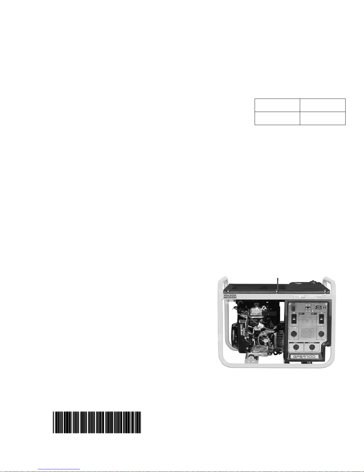
Generator
GS 8.5V
GPS 8500
GS 9.7V
GPS 9700
REPAIR MANUAL
0174423EN


GPS 8500/GPS 9700 Foreword
Foreword
Machines
covered by
this manual
Machine Item Number
GPS 8500 (GS 8.5V) 0008286
GPS 9700 (GS 9.7V) 0008287
GPS 9700 0620264
Machine
documentation
Expectations
for
information in
this manual
Keep a copy of the Operator’s Manual with the machine at all times.
Use the separate Parts Book supplied with the machine to order replacement
parts.
Refer to the separate Repair Manual for detailed instructions on servicing and
repairing the machine.
If you are missing any of these documents, please contact Wacker Neuson Cor-
poration to order a replacement or visit www.wackerneuson.com.
When ordering parts or requesting service information, be prepared to provide
the machine model number, item number, revision number, and serial number.
This manual provides information and procedures to safely operate and main-
tain the above Wacker Neuson model(s). For you r own safety and to reduce the
risk of injury, carefully read, understand, and observe all instructions described
in this manual.
Wacker Neuson Corporation expressly reserves the right to make technical
modifications, even without notice, which improve the performance or safety
standards of its machines.
The information contained in this manual is based on machines manufactured
up until the time of publication. Wacker Neuson Co rporation reserves the right to
change any portion of this information without notice.
Copyright
notice
All rights, especially copying and distribution rights, are reserved.
Copyright 2009 by Wacker Neuson Corporation.
This publication may be reproduced through photocopying by the original
purchaser of the machine. Any other type of reproduction is prohibited without
express written permission from Wacker Neuson Corporation.
Any type of reproduction or distribution not authorized by Wacker Neuson Cor-
poration represents an infringement of valid copyrights, and violators will be
prosecuted.
CALIFORNIA
Proposition
65 Warning:
Laws
pertaining to
spark
arresters
Engine exhaust, some of its constituents, and certain vehicle components, contain
or emit chemicals known to the State of California to cause cancer and birth
defects or other reproductive harm.
NOTICE: State Health Safety Codes and Public Resources Codes specify that in
certain locations spark arresters be used on internal combustion engines that use
hydrocarbon fuels. A spark arrester is a device designed to prevent accidental discharge of sparks or flames from the engine exhaust. Spark arresters are qualified
and rated by the United States Forest Service for this purpose. In order to comply
wc_tx000827gb.fm 3

Foreword GPS 8500/GPS 9700
with local laws regarding spark arresters, consult the engine distributor or the local
Health and Safety Administrator.
Trademarks
All trademarks referenced in this manual are the property of their respective owners.
wc_tx000827gb.fm 4

GPS 8500/GPS 9700 Table of Contents
Foreword 3
1 Safety Information 7
1.1 Laws Pertaining to Spark Arresters ...................................................... 7
1.2 Operating Safety .................................................................................. 8
1.3 Operator Safety While Using Internal Combustion Engines ................. 9
1.4 Service Safety .................................................................................... 10
2 Operation 12
2.1 Control Panel ...................................................................................... 12
2.2 Voltage Selection ............................................................................... 13
2.3 Engine Auto Idle ................................................................................. 13
2.4 To Run the Generator ........................................................................ 14
2.5 To Stop the Generator ........................................................................ 15
3 Troubleshooting Voltage Issues 16
3.1 Determining Where to Begin .............................................................. 16
3.2 Flashing the Generator ....................................................................... 18
3.3 Checking the Automatic Voltage Regulator (AVR) ............................. 20
3.4 Checking the Stator Windings ............................................................ 21
3.5 Checking the Rotor Windings ............................................................. 23
3.6 Checking the Brushes ........................................................................ 24
3.7 Checking the Diode Rectifier .............................................................. 25
3.8 Checking the Auxiliary Winding .......................................................... 26
3.9 Checking the Choke ........................................................................... 27
3.10 Checking the Transformer .................................................................. 28
3.11 Checking the Voltage Selector Switch (VSS) ..................................... 29
3.12 Checking the Auto Idle Circuit ............................................................ 30
4 Disassembly and Assembly 33
4.1 Tools Required for Disassembly/Assembly Procedures ..................... 33
4.2 Information Regarding Replacement Parts ........................................ 33
wc_br0174423en_002TOC.fm 5

Table of Contents GPS 8500/GPS 970
4.3 Information Regarding Reference Numbers ( ) ...................................33
4.4 Information Regarding Threadlocking Compounds .............................33
4.5 Generator Exploded View ...................................................................34
4.6 Exploded View Components ...............................................................35
4.7 Removing & Installing the Fuel Tank ...................................................36
4.8 Removing & Installing the Automatic Voltage Regulator (AVR) ..........37
4.9 Removing the Stator and Rotor ...........................................................38
4.10 Installing the Stator and Rotor .............................................................41
4.11 Removing and Installing the Electronic Governor ...............................44
5 Schematics 46
5.1 Generator Wiring Schematic ...............................................................46
5.2 Schematic Components ......................................................................47
5.3 Generator Wiring Schematic (Revision 104 and below) ......................48
5.4 Schematic Components (Revision 104 and below) .............................49
5.5 Engine Wiring Diagram .......................................................................50
6 Technical Data 51
6.1 Generator ............................................................................................51
6.2 Windings ..............................................................................................51
6.3 Engine .................................................................................................52
wc_br0174423en_002TOC.fm 6
GPS 8500/GPS 9700 Safety Information
1 Safety Information
This manual contains DANGER, WARNING, CAUTION, NOTICE, and
NOTE callouts which must be followed to reduce the possibility of
personal injury, damage to the equipment, or improper service.
This is the safety alert symbol. It is used to alert you to potential
personal injury hazards. Obey all safety messages that follow this
symbol to avoid possible injury or death.
DANGER indicates a hazardous situation which, if not avoided, will
result in death or serious injury.
DANGER
WARNING indicates a hazardous situation which, if not avoided, could
result in death or serious injury.
WARNING
CAUTION indicates a hazardous situation which, if not avoided, could
result in minor or moderate injury.
CAUTION
NOTICE: Used without the safety alert symbol, NOTICE indicates a
situation which, if not avoided, could result in property damage.
Note: Contains additional information important to a procedure.
1.1 Laws Pertaining to Spark Arresters
Notice: State Health Safety Codes and Public Resources Codes
specify that in certain locations spark arresters be used on internal
combustion engines that use hydrocarbon fuels. A spark arrester is a
device designed to prevent accidental discharge of sparks or flames
from the engine exhaust. Spark arresters are qualified and rated by
the United States Forest Service for this purpose.
In order to comply with local laws regarding spark arresters, consult
the engine distributor or the local Health and Safety Administrator.
wc_si000252gb.fm 7
Safety Information GPS 8500/GPS 9700
1.2 Operating Safety
BACKFEED FROM THE GENERATOR INTO THE PUBLIC POWER
DISTRIBUTION SYSTEM CAN CAUSE SERIOUS INJURY OR
DEATH TO UTILITY WORKERS!
DANGER
WARNING
Improper connection of generator to a building’s electrical system can
allow electrical current from the generator to backfeed into utility lines.
This may result in electrocution of utility workers, fire, or explosion.
Connections to a building’s electrical system must be made by a
qualified electrician and comply with all applicable laws and electrical
codes.
If connected to a building’s electrical system the generator must meet
the power, voltage, and frequency requirements of the equipment in
the building. Differences in power, voltage, and frequency
requirements may exist and improper connection may lead to
equipment damage, fire, and personal injury or death.
Familiarity and proper training are required for the safe operation of the
machine. Machines operated improperly or by untrained personnel
can be hazardous. Read the operating instructions contained in this
manual and the engine manual, and familiarize yourself with the
location and proper use of all controls. Inexperienced operators should
receive instruction from someone familiar with the machine before
being allowed to operate it.
1.2.1 NEVER operate the generator when open containers of fuel, paint, or
other flammable liquids are near.
1.2.2 NEVER operate the generator, or tools attached to the generator, with
wet hands.
1.2.3 NEVER use worn electrical cords. Severe electrical shock and
equipment damage may result.
1.2.4 NEVER run the electrical cords under the generator, or over vibrating
or hot parts.
1.2.5 NEVER enclose or cover the generator when it is in use or when it is
hot.
1.2.6 NEVER overload the generator. The total amperage of the tools and
equipment attached to the generator must not exceed the load rating
of the generator.
1.2.7 NEVER operate the machine in snow, rain, or standing water.
1.2.8 NEVER allow untrained personnel to operate or service the generator.
The generator set should be set up by a certified electrician.
1.2.9 Store the machine properly when it is not being used. The machine
should be stored in a clean, dry location out of the reach of children.
1.2.10 Be sure the machine is on a firm, level surface and will not tip, roll,
slide, or fall while operating.
wc_si000252gb.fm 8

GPS 8500/GPS 9700 Safety Information
1.2.11 ALWAYS transport the generator in an upright position.
1.2.12 ALWAYS keep the machine at least one meter (three feet) away from
structures, buildings, and other equipment during use.
1.2.13 ALWAYS keep the area immediately surrounding and underneath the
machine clean, neat, and free of debris and combustible materials.
Make sure that the area overhead is clear of debris that could fall onto
or into the machine or exhaust compartment.
1.2.14 ALWAYS remove all tools, cords, and other loose items from the
generator before starting it.
1.2.15 ALWAYS make certain the machine is well-grounded and securely
fastened to a good earthen ground per national and local regulations.
1.3 Operator Safety While Using Internal Combustion Engines
Internal combustion engines present special hazards during operation
and fueling. Read and follow the warning instructions in the engine
owner’s manual and the safety guidelines below. Failure to follow the
WARNING
warnings and safety standards could result in severe injury or death.
1.3.1 NEVER use this generator inside a home or garage, EVEN IF doors
and windows are open. Only use OUTSIDE and far away from
windows, doors, and vents. Using a generator indoors CAN KILL YOU
IN MINUTES. Generator exhaust contains carbon monoxide. This is a
poison you cannot see or smell.
1.3.2 NEVER use a generator inside an enclosed area such as a tunnel or a
trench.
1.3.3 Do not smoke while operating the machine.
1.3.4 Do not smoke when refueling the engine.
1.3.5 Do not refuel a hot or running engine.
1.3.6 Do not refuel the engine near an open flame.
1.3.7 Do not spill fuel when refueling the engine.
1.3.8 Do not run the engine near open flames.
1.3.9 Do not start the engine if fuel has spilled or a fuel odor is present. Move
the generator away from the spill and wipe the generator dry before
starting.
1.3.10 Refill the fuel tank in a well-ventilated area.
1.3.11 Replace the fuel tank cap after refueling.
1.3.12 ALWAYS check the fuel lines and the fuel tank for leaks and cracks
before starting the engine. Do not run the machine if fuel leaks are
present or the fuel lines are loose.
wc_si000252gb.fm 9

Safety Information GPS 8500/GPS 9700
1.4 Service Safety
Poorly maintained equipment can become a safety hazard! In order
for the equipment to operate safely and properly over a long period of
time, periodic maintenance and occasional repairs are necessary. If
WARNING
1.4.1 Do not use gasoline or other types of fuels or flammable solvents to
1.4.2 DO NOT attempt to clean or service the machine while it is running.
1.4.3 Do not modify the machine without the express written approval of the
1.4.4 DO NOT allow water to accumulate around the base of the machine.
1.4.5 DO NOT service the machine if your clothing or skin is wet.
the generator is experiencing problems or is being serviced, attach a
“DO NOT START” sign to the control panel to notify other people of its
condition.
clean parts, especially in enclosed areas. Fumes from fuels and
solvents can become explosive.
manufacturer.
If water is present, move the machine and allow the machine to dry
before servicing.
1.4.6 DO NOT allow untrained personnel to service this equipment. Only
trained electrical technicians should be allowed to service the electrical
components of this equipment.
1.4.7 Keep the machine clean and labels legible. Replace all missing and
hard-to-read labels. Labels provide important operating instructions
and warn of dangers and hazards.
1.4.8 ALWAYS replace the safety devices and guards after repairs and
maintenance.
1.4.9 ALWAYS let the engine cool before transporting or servicing the
machine.
1.4.10 ALWAYS keep hands, feet, and loose clothing away from the moving
parts on the generator and engine.
1.4.11 ALWAYS turn the engine off before servicing the machine. If the
engine has electric start, disconnect the negative terminal on the
battery before servicing the machine.
1.4.12 ALWAYS keep the fuel lines in good condition and properly connected.
Leaking fuel and fumes are extremely explosive.
wc_si000252gb.fm 10

GPS 8500/GPS 9700 Safety Information
Notes
wc_si000252gb.fm 11
Operation GPS 8500/GPS 9700
2 Operation
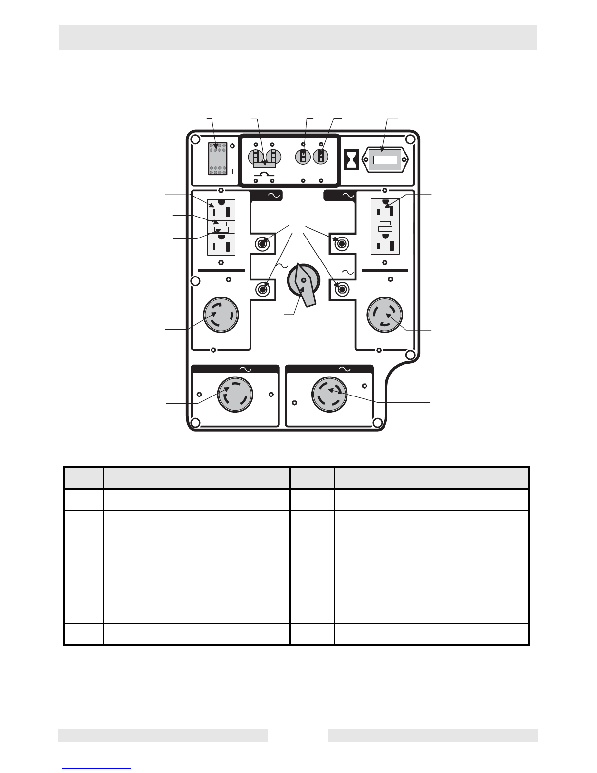
2.1 Control Panel
f
f1
f2
j
a
b e
IDLE
120
20 A 30 A
120
g
120
120/
240
h
30 A
240
120/240
dc
000000
f
k
20 A
m
20 A
30 A
n
Ref. Description Ref. Description
a Auto Idle Switch g Thermal Overload
b Main Circuit Breaker h Voltage Selector Switch
c 240V 20A Overcurrent Circuit
j 120V 30A Twist-lock Receptacle
Breaker
d 120/240V 30A Overcurrent Circuit
k 120V 20A Twist-lock Receptacle
Breaker
e Hour meter m 240V 20A Twist-lock Receptacle
f 120V GFI Duplex Receptacle n 120/240V Twist-lock Receptacle
wc_tx001265gb.fm 12

GPS 8500/GPS 9700 Operation
2.2 Voltage Selection
The voltage selector switch (h) allows the generator to operate in either single
(120V) or dual voltage (120/240V) mode.
In single voltage mode only the 120V twist lock and 120V duplex receptacles are
powered. The full rated power of the generator is shared between the four
receptacles.
In dual voltage mode both the 120V and 240V receptacles are powered; however,
only half the rated power is available at the 120V GFI receptacles and half at the
120V twist lock receptacle. Full power is available at the 240V twist lock receptacle.
NOTICE: NEVER switch the volt age selector switch with the main breaker on! Th is
can cause arcing and can damage the generator. T urn all too ls and appliances off
and place main breaker in the “OFF” (open) position (O) before changing the
voltage switch position.
2.3 Engine Auto Idle
The auto idle switch (a) automatically reduces engine speed 5 seconds after all
appliances or tools attached to the generator have been turned off. Engine
automatically returns to full speed when a tool or appliance is turned back on.
To turn auto idle feature on, push auto idle switch to ON (I). This position is
recommended while the generator is running to minimize fuel consumption. To
avoid extended engine warm-up periods, keep switch OFF (O) when starting the
engine and until engine reaches operating temperature.
wc_tx001265gb.fm 13

Operation GPS 8500/GPS 9700
2.4 To Run the Generator
Follow instructions below and read starting and stopping instuctions found in
Engine Owner’s Manual.
1. Ensure that the generator is properly installed in an outdoor location. See
Sections Installation and Operator Safety while using Internal Combustion
Engines for installation warnings and safety guidelines.
2. Disconnect all loads from the generator and place the main circuit breaker in the
open (O) position. Place auto idle switch to OFF (O) position.
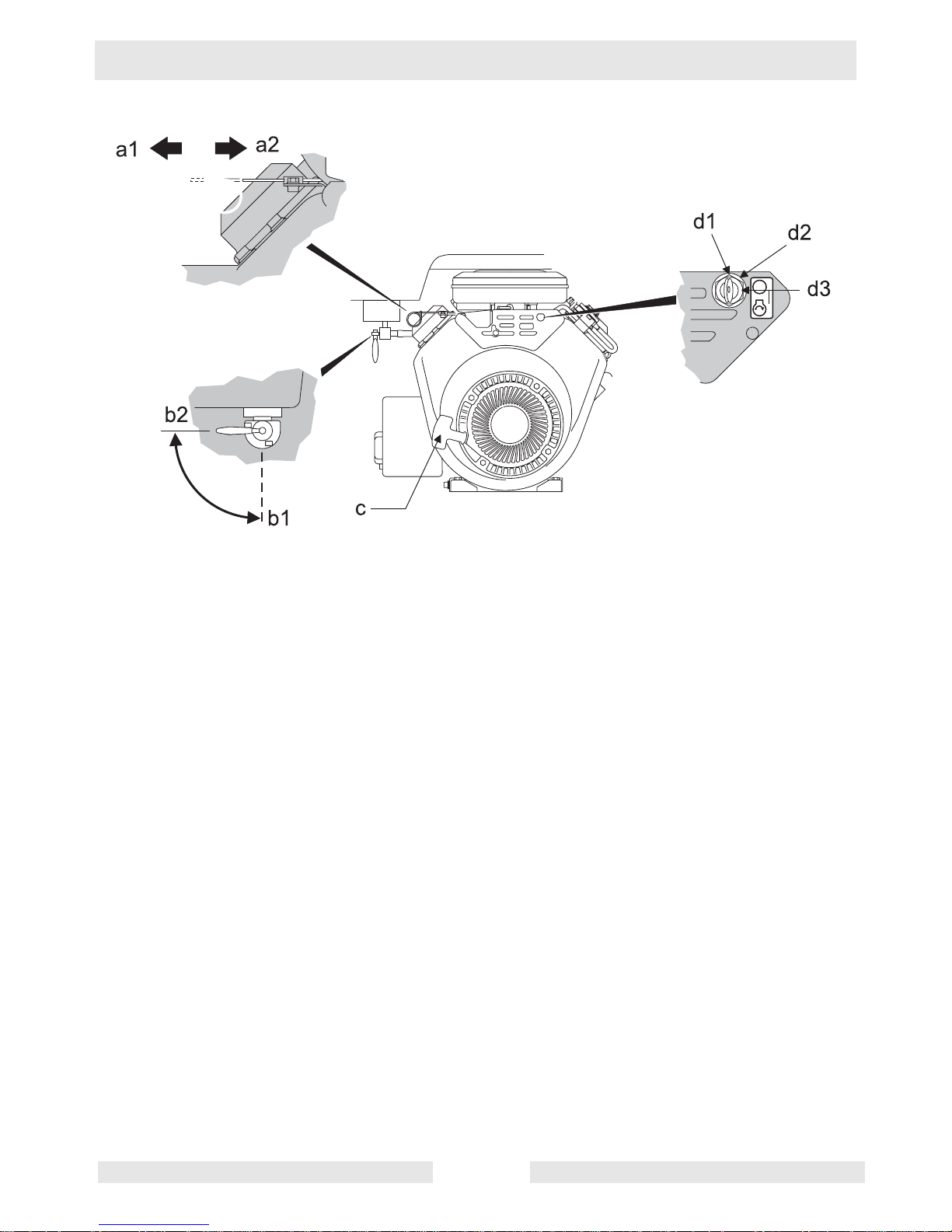
3. Open fuel valve (b1).
4. If engine is cold, pull choke control out (a1). If engine is hot, push choke control
in (a2).
5. Turn key switch to the start position (d3) and hold until engine starts.
NOTICE: Do not crank engine longer than 15 seconds at a time. Extended
cranking can damage starter motor.
To start engine using manual start: Turn key switch to the run position (d2). Pull
starter rope (c) rapidly to start engine.
Leave key in run position (
Note: Turn the keyswitch to the OFF position when the engine is not running.
Leaving the key in the RUN position with the engine off will drain the battery.
Note: Although the engine will start manually and will run without a battery, it will
only idle and the generator will not load, as the governor requires that a battery be
connected. See “Recommended Battery.”
Note: The engine is equipped with a low oil protection system. If the o il level is low,
the engine will not start. Check engine oil level if engine does not start.
d2) while engine is running.
6. Push choke in as engine warms (a2).
7. Place main circuit breaker in closed (l) position and place auto idle switch in ON
(l) position. Allow engine to warm up and check function of GFI circuit breakers
before attaching loads to generator (see Ground Fault Circuit Interrupt).
wc_tx001265gb.fm 14
GPS 8500/GPS 9700 Operation
2.5 To Stop the Generator
1. Disconnect all loads from generator and place main circuit breaker in open
position.
2. Turn engine switch to the stop position (d1).
3. Close fuel valve (b2).
wc_tx001265gb.fm 15
Troubleshooting Voltage Issues GPS 8500/GPS 9700
3 Troubleshooting Voltage Issues
3.1 Determining Where to Begin
Prerequisites
Procedure
Generator must be able to begin
Multimeter
To determine where to start troubleshooting, follow the procedure below.
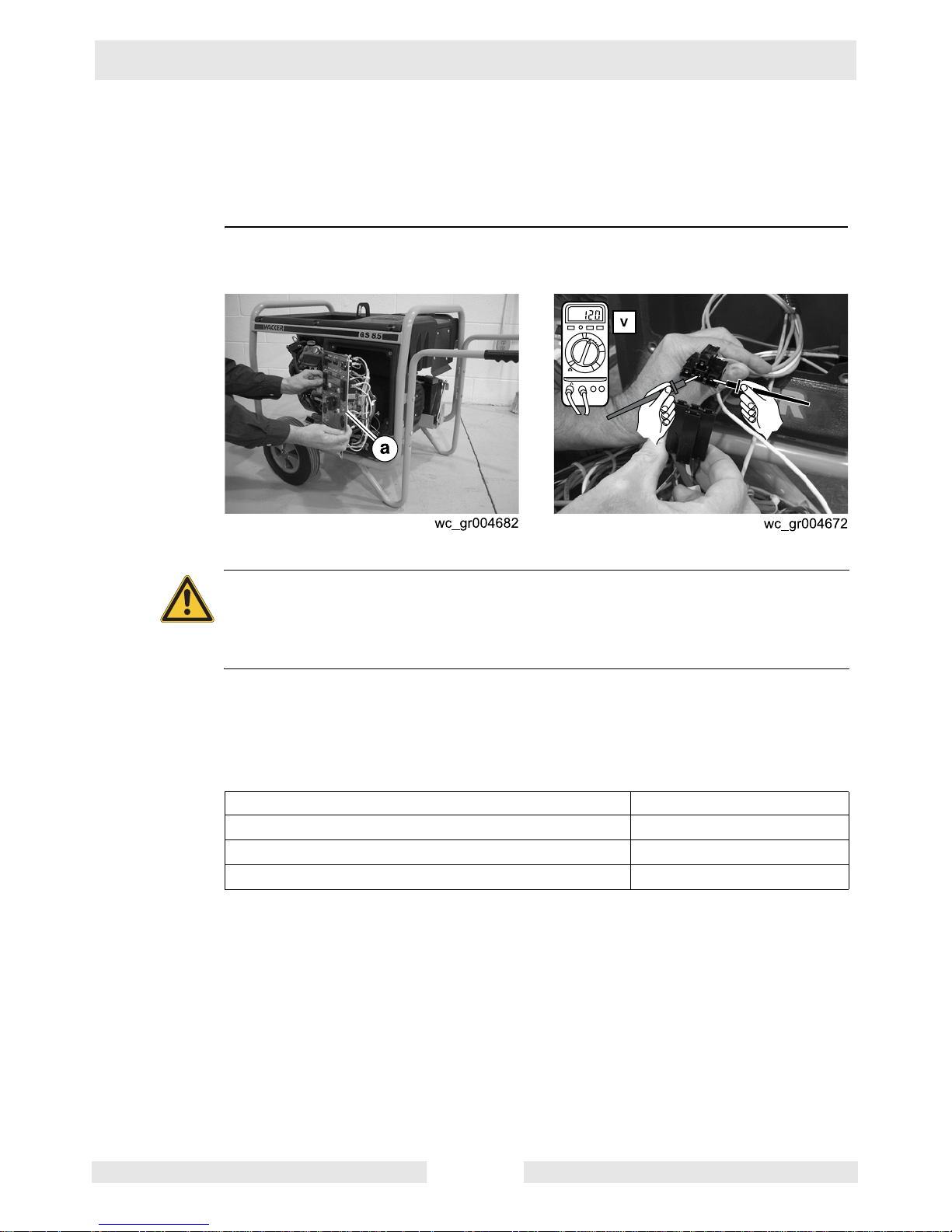
1. Remove the control panel (a) from the generator.
1000
F
200
V
20
2
200m
A
V- COM
2. Disconnect the main wiring connector.
WARNING
Electric shock hazard. High voltage exists at the connector. High voltage can cause
severe injury or death.
f Never touch the internal terminals of the connector while the engine is running.
3. Start the engine.
4. Place the auto idle switch in the OFF position.
5. Measure the voltage between the red and white wires; also measure the
voltage between the blue and brown wires.
If Then
Between 100–140 VAC is measured in both locations, begin with step 10.
If 1.5 VAC or lower is measured in both locations, begin with step 1.
If more than 1.5 VAC is measured in both locations, begin with step 2.
6. Turn off the engine.
This procedure continues on the next page.
wc_tx000828gb.fm 16
GPS 8500/GPS 9700 Troubleshooting Voltage Issues
Continued from the previous page.
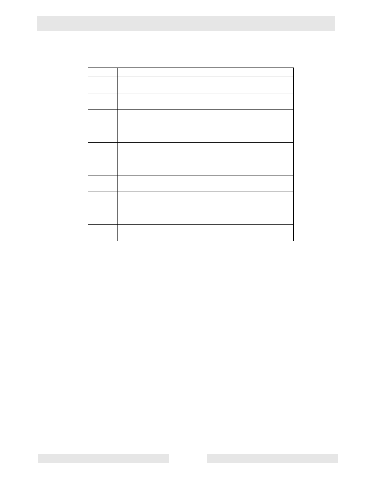
Sequence
Follow the sequence below when troubleshooting:
Step Task
1
2
3
4
5
6
7
8
9
10
Flash the generator.
See section Flashing the Generator.
Check the Automatic Voltage Regulator (AVR).
See section Checking the Automatic Voltage Regulator (AVR).
Check the stator windings.
See section
Check the rotor winding.
See section Checking the Rotor Winding.
Check the brushes.
See section Checking the Brushes.
Check the diode rectifier.
See section Checking the Diode Rectifier.
Check the auxiliary winding.
See section Checking the Auxiliary Winding.
Check the choke.
See section Checking the Choke
Check the transformer.
See section Checking the Transformer.
Check the Volt age Selector Switch (VSS).
See section Checking the Voltage Selector Switch .
Checking Stator Winding.
wc_tx000828gb.fm 17
Troubleshooting Voltage Issues GPS 8500/GPS 9700
3.2 Flashing the Generator
Prerequisites
Procedure
12V battery
Multimeter
Follow the procedure below to flash the generator.
1. Shut down the generator.
2. Disconnect all loads from the generator.
3. Place the auto idle switch in the OFF position.
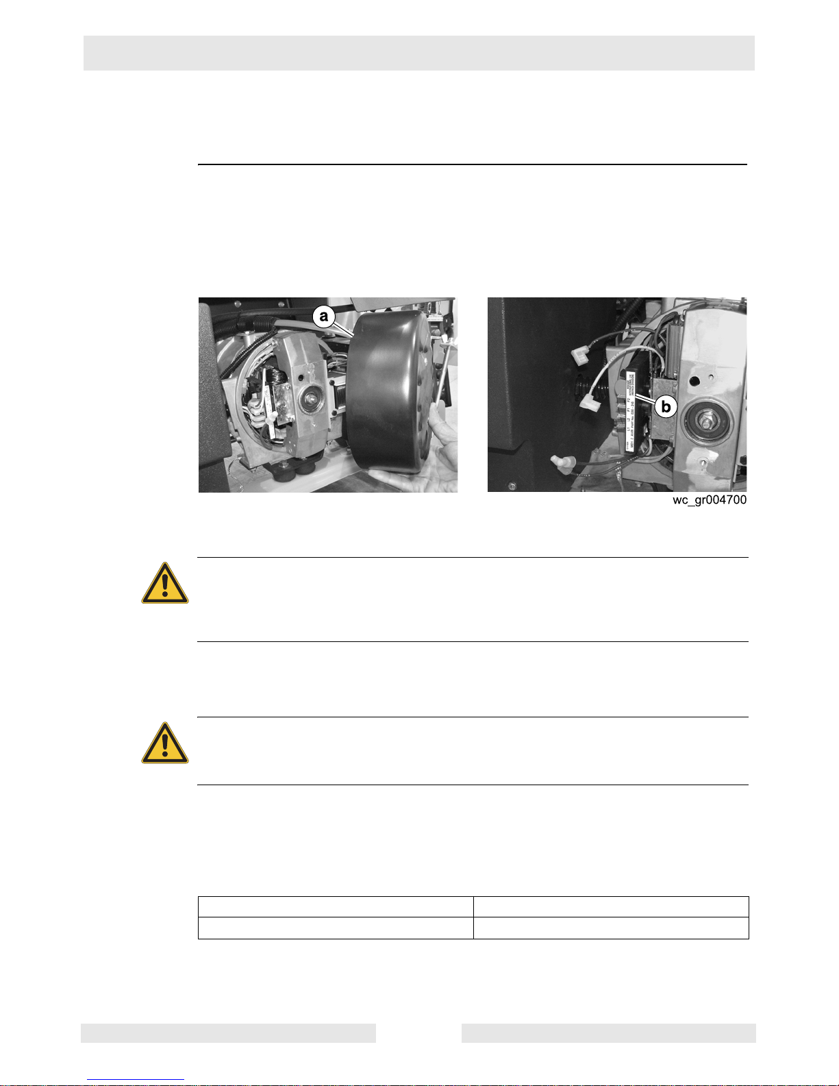
4. Remove the rear panel (a) from the generator.
5. Disconnect the F1 (+) and F2 (-) wires and the L1 and L2 wires from the
Automatic Voltage Regulator (AVR) (b).
WARNING
Electric shock hazard. High voltage exists at the L1 and L2 wires. Electric shock
can cause severe injury or death.
f Never touch the L1 and L2 wires while the engine is running.
6. Start the engine.
7. Check the engine rpm. It should be approximately 3750 rpm.
WARNING
Explosion hazard. Batteries produce hydrogen gas during normal operation.
f Keep sparks away from the battery.
8. Connect the 12V battery to the F1 (+) and F2 (-) wires; battery positive to F 1
(+), battery negative to F2 (-).
9. Measure the voltage between the L1 wire and the L2 wire.
Is 120–160 VAC measured?
Yes ____ No ____
Continue Check the stator windings.
10.Reassemble the generator.
This procedure continues on the next page.
wc_tx000828gb.fm 18
 Loading...