

Wacker Neuson GP 3800A, GP 5600A, GP 6600A Repair Manual

www.wackergroup.com
Generator
GP 2500A
GP 3800A
GP 5600A
GPS 5600A
GP 6600A
GPS 6600A
REPAIR MANUAL
0160415en 001
0806
0160415EN


GP Repair Foreword
wc_tx000544gb.fm i
Operating / Parts Information
You must be familiar with the operation of this machine before you
attempt to troubleshoot or repair it. Basic operating and maintenance
procedures are described in the Operator’s Manual supplied with the
machine. Keep a copy of the Operator’s Manual with the machine at all
times. Use the separate Parts Book supplied with the machine to order
replacement parts. If you are missing either of the documents, please
contact Wacker Corporation to order a replacement.
Damage caused by misuse or neglect of the unit should be brought to
the attention of the operator to prevent similar occurrences from
happening in the future.
This manual provides information and procedures to safely repair and
maintain the above Wacker model(s). For your own safety and
protection from injury, carefully read, understand, and observe all
instructions described in this manual. THE INFORMATION
CONTAINED IN THIS MANUAL IS BASED ON MACHINES
MANUFACTURED UP TO THE TIME OF PUBLICATION. WACKER
CORPORATION RESERVES THE RIGHT TO CHANGE ANY
PORTION OF THIS INFORMATION WITHOUT NOTICE.
This manual covers machines with Item Number:
0620009, 0620010, 0620011, 0620012, 0620013, 0620014, 0620015,
0620016, 0620041, 0620042, 0620043, 0620044, 0620045, 0620046,
0620047

Foreword GP Repair
wc_tx000544gb.fm ii
CALIFORNIA
Proposition 65 Warning:
Engine exhaust, some of its constituents, and certain vehicle
components, contain or emit chemicals known to the State of
California to cause cancer and birth defects or other reproductive
harm.
Laws Pertaining to Spark Arresters
Notice: State Health Safety Codes and Public Resources Codes
specify that in certain locations spark arresters be used on internal
combustion engines that use hydrocarbon fuels. A spark arrester is a
device designed to prevent accidental discharge of sparks or flames
from the engine exhaust. Spark arresters are qualified and rated by
the United States Forest Service for this purpose.
In order to comply with local laws regarding spark arresters, consult
the engine distributor or the local Health and Safety Administrator.
All rights, especially copying and distribution rights, are reserved.
Copyright 2006 by Wacker Corporation
No part of this publication may be reproduced in any form or by any
means, electronic or mechanical, including photocopying, without
express written permission from Wacker Corporation.
Any type of reproduction or distribution not authorized by Wacker
Corporation represents an infringement of valid copyrights, and
violators will be prosecuted. We expressly reserve the right to make
technical modifications, even without due notice, which aim at
improving our machines or their safety standards.
WARNING

GP Repair Table of Contents
wc_br0160415en_001TOC.fm 1
1. Safety Information 4
1.1 Operating Safety .................................................................................. 5
1.2 Operator Safety while using Internal Combustion Engines .................. 7
1.3 Service Safety ...................................................................................... 8
1.4 Label Locations .................................................................................... 9
1.5 Safety and Operating Labels .............................................................. 10
2. Technical Data 14
2.1 Generator—GP 2500A ....................................................................... 14
2.2 Engine—GP 2500A ............................................................................ 15
2.3 Generator—GP 3800A, GP 3800A CAN ............................................ 16
2.4 Engine—GP 3800A, GP 3800A CAN ................................................. 17
2.5 Generator—GP/GPS 5600A/5600A CAN .......................................... 18
2.6 Engine—GP/GPS 5600A/5600A CAN ............................................... 20
2.7 Generator—GP/GPS 6600A/6600A CAN .......................................... 22
2.8 Engine—GP/GPS 6600A/6600A CAN ............................................... 24
3. Operation 25
3.1 Information Regarding Operation ....................................................... 25
3.2 Determining Power Requirements ..................................................... 25
3.3 Outdoor Installation ............................................................................ 27
3.4 Indoor Installation ............................................................................... 27
3.5 Recommended Battery (GPS only) .................................................... 27
3.6 Generator Derating ............................................................................. 28
3.7 Grounding the Generator ................................................................... 29
3.8 Control Panel ...................................................................................... 30
3.9 Control Panel—GP 3800 .................................................................... 31
3.10 Control Panel—GP 5600/GP6600 ...................................................... 32
3.11 Ground Fault Interrupt (GFI) ............................................................... 33
3.12 Twist-Lock Receptacles ..................................................................... 33
3.13 Engine Auto Idle ................................................................................. 34
3.14 Engine Speed ..................................................................................... 34
3.15 Voltage Selection ............................................................................... 35
3.16 To Start ............................................................................................... 36
3.17 To Stop ............................................................................................... 37

Table of Contents GP Repair
wc_br0160415en_001TOC.fm 2
4. Maintenance 38
4.1 Engine Maintenance ............................................................................38
4.2 Periodic Maintenance Schedule ..........................................................38
4.3 Engine Oil ............................................................................................39
4.4 Servicing Air Cleaner ...........................................................................40
4.5 Spark Plug ...........................................................................................41
4.6 Cleaning the Sediment Cup ................................................................42
4.7 Carburetor Adjustment ........................................................................42
4.8 Adjusting Engine Speed ......................................................................43
4.9 Storage ................................................................................................44
4.10 Transport .............................................................................................45
4.11 Electrical Schematic—GP 2500A ........................................................46
4.12 Components—GP 2500A ....................................................................47
4.13 Electrical Schematic—GP 3800A (0620010 rev. < 104) .....................48
4.14 Components—GP 3800A (0620010 rev. < 104) .................................49
4.15 Electrical Schematic—GP 3800A (0620010 rev. > 103) .....................50
4.16 Components—GP 3800A (0620010 rev. > 103) .................................51
4.17 Electrical Schematic—GP 3800A CAN (0620041 rev. < 104) .............52
4.18 Components—GP 3800A CAN (0620041 rev. < 104) .........................53
4.19 Electrical Schematic—GP 3800A CAN (0620041 rev. > 103) .............54
4.20 Components—GP 3800A CAN (0620041 rev. > 103) .........................55
4.21 Electrical Schematic—GP/GPS 5600A/6600A (rev. < 104) ................56
4.22 Components—GP/GPS 5600A/6600A (rev. < 104) ............................57
4.23 Electrical Schematic—GP/GPS 5600A/6600A (rev. > 103) ................58
4.24 Components—GP/GPS 5600A/6600A (rev. > 103) ............................59
4.25 Electrical Schematic (CAN)—GP/GPS 5600A/6600A (rev. < 104) .....60
4.26 Components (CAN)—GP/GPS 5600A/6600A (rev. < 104) .................61
4.27 Electrical Schematic (CAN)—GP/GPS 5600A/6600A (rev. >103) ......62
4.28 Components (CAN)—GP/GPS 5600A/6600A (rev. > 103) .................63
4.29 Engine Schematic (all)—GP/GPS 3800A/5600A/6600A .....................64
4.30 Engine Components (all)—GP/GPS 3800A/5600A/6600A .................65
5. Theory of Operation 67
5.1 Introduction ..........................................................................................67
5.2 Windings and Fields ............................................................................68
5.3 Voltage Regulation ..............................................................................69
5.4 Auto Idle Circuit ...................................................................................70
5.5 Anti-Afterfire Circuit .............................................................................71

GP Repair Table of Contents
wc_br0160415en_001TOC.fm 3
6. Troubleshooting 72
6.1 Troubleshooting Methodology ............................................................ 72
6.2 Checking Continuity ........................................................................... 74
6.3 Checking Resistance .......................................................................... 74
6.4 Checking Voltage ............................................................................... 74
6.5 Troubleshooting Flowcharts ............................................................... 75
6.6 No Voltage at Receptacles—Flowchart 1A ........................................ 76
6.7 No Voltage at Receptacles—Flowchart 1B ........................................ 77
6.8 Checking Voltage at Generator Terminal Strip ................................... 78
6.9 Checking Voltage at Plug—GP 2500A ............................................... 79
6.10 Checking Main and Rotor Windings ................................................... 80
6.11 No Voltage at Receptacles—Flowchart 1C ........................................ 82
6.12 Checking Main Circuit Breaker and Receptacle Circuitry ................... 84
6.13 Low Voltage at Receptacles—Flowchart 2A ...................................... 86
6.14 Checking Brushes .............................................................................. 87
6.15 Checking Excitation Winding .............................................................. 88
6.16 Checking AVR’s Sensing Wires—GP 2500A ..................................... 90
6.17 Checking AVR’s Sensing Wires ......................................................... 92
6.18 Confirming a Malfunctioning AVR ...................................................... 94
6.19 Checking and Installing the Voltage Selector Switch (VSS) ............... 96
6.20 High Voltage Troubleshooting—Flowchart 3A ................................... 98
6.21 Auto Idle Circuit Troubleshooting—Flowchart 4A ............................... 99
6.22 Checking Voltage to Auto Idle Solenoid ........................................... 100
6.23 Checking Auto Idle Circuitry Between Generator and Fuse ............. 102
6.24 Checking Auto Idle Circuitry Between Fuse and Auto Idle Unit ....... 104
6.25 Engine Backfires—Troubleshooting Flowchart 5A ........................... 105
6.26 Checking Anit-Afterfire Solenoid (AAS) Circuit ................................. 106
7. Disassembly/Assembly Procedures 109
7.1 Tools ................................................................................................. 109
7.2 Ordering Parts .................................................................................. 109
7.3 Reference Numbers ( ) ..................................................................... 109
7.4 Weight Block .................................................................................... 109
7.5 Replacing the Muffler ....................................................................... 110
7.6 Replacing the Fuel Tank .................................................................. 112
7.7 Replacing the Stator ......................................................................... 114
7.8 Replacing the Rotor .......................................................................... 116
7.9 Replacing the Engine ....................................................................... 118
Safety Information GP Repair
wc_si000169gb.fm 4
1. Safety Information
This manual contains DANGER, WARNING, CAUTION, and NOTE
callouts which must be followed to reduce the possibility of personal
injury, damage to the equipment, or improper service.
This is the safety alert symbol. It is used to alert you to potential
personal injury hazards. Obey all safety messages that follow this
symbol to avoid possible injury or death.
DANGER indicates a hazardous situation which, if not avoided, will
result in death or serious injury.
WARNING indicates a hazardous situation which, if not avoided, could
result in death or serious injury.
CAUTION indicates a hazardous situation which, if not avoided, could
result in minor or moderate injury.
CAUTION: Used without the safety alert symbol, CAUTION indicates
a potentially hazardous situation which, if not avoided, may result in
property damage.
Note: Contains additional information important to a procedure.
DANGER
WARNING
CAUTION

GP Repair Safety Information
wc_si000169gb.fm 5
1.1 Operating Safety
BACKFEED FROM THE GENERATOR INTO THE PUBLIC POWER
DISTRIBUTION SYSTEM CAN CAUSE SERIOUS INJURY OR
DEATH TO UTILITY WORKERS!
Improper connection of generator to a building's electrical system can
allow electrical current from the generator to backfeed into utility lines.
This may result in electrocution of utility workers, fire, or explosion.
Connections to a building's electrical system must be made by a
qualified electrician and comply with all applicable laws and electrical
codes.
If connected to a building's electrical system the generator must meet
the power, voltage, and frequency requirements of the equipment in
the building. Differences in power, voltage, and frequency
requirements may exist and improper connection may lead to
equipment damage, fire, and personal injury or death.
Familiarity and proper training are required for the safe operation of
equipment. Equipment operated improperly or by untrained personnel
can be dangerous. Read the operating instructions contained in both
this manual and the engine manual and familiarize yourself with the
location and proper use of all controls. Inexperienced operators should
receive instruction from someone familiar with the equipment before
being allowed to operate the machine.
1.1.1 NEVER operate the generator when open containers of fuel, paint, or
other flammable liquids are near.
1.1.2 NEVER operate the generator, or tools attached to the generator, with
wet hands.
1.1.3 NEVER use worn electrical cords. Severe electrical shock and
equipment damage may result.
1.1.4 NEVER run the electrical cords under the generator, or over vibrating
or hot parts.
1.1.5 NEVER enclose or cover the generator when it is in use or when it is
hot.
1.1.6 NEVER overload the generator. The total amperage of the tools and
equipment attached to the generator must not exceed the load rating
of the generator.
1.1.7 NEVER operate the machine in snow, rain, or standing water.
1.1.8 NEVER allow untrained personnel to operate or service the generator.
The generator set should be set up by a trained electrician.
1.1.9 NEVER stand on the machine.
1.1.10 DO NOT stand under the machine while it is being hoisted or moved.
1.1.11 DO NOT attach equipment to the machine when it is suspended.
DANGER
WARNING

Safety Information GP Repair
wc_si000169gb.fm 6
1.1.12 ALWAYS store the equipment properly when it is not being used.
Equipment should be stored in a clean, dry location out of the reach of
children.
1.1.13 ALWAYS position and operate the generator on a firm,
noncombustible, level surface.
1.1.14 ALWAYS transport the generator in an upright position.
1.1.15 ALWAYS keep the machine at least one meter (three feet) away from
structures, buildings, and other equipment during use.
1.1.16 ALWAYS keep the area immediately surrounding and underneath the
machine clean, neat, and free of debris and combustible materials.
Make sure that the area overhead is clear of debris that could fall onto
or into the machine or exhaust compartment.
1.1.17 ALWAYS remove all tools, cords, and other loose items from the
generator before starting it.
1.1.18 ALWAYS make certain the machine is well-grounded and securely
fastened to a good earthen ground per national and local regulations.

GP Repair Safety Information
wc_si000169gb.fm 7
1.2 Operator Safety while using Internal Combustion En gines
Internal combustion engines present special hazards during operation
and fueling. Read and follow the warning instructions in the engine
owner’s manual and the safety guidelines below. Failure to follow the
warnings and safety guidelines could result in severe injury or death.
1.2.1 DO NOT run the machine indoors or in an enclosed area such as a
deep trench unless adequate ventilation, through such items as
exhaust fans or hoses, is provided. Exhaust gas from the engine
contains poisonous carbon monoxide gas; exposure to carbon
monoxide can cause loss of consciousness and may lead to death.
1.2.2 DO NOT smoke while operating the machine.
1.2.3 DO NOT smoke when refueling the engine.
1.2.4 DO NOT refuel a hot or running engine.
1.2.5 DO NOT refuel the engine near an open flame.
1.2.6 DO NOT spill fuel when refueling the engine.
1.2.7 DO NOT run the engine near open flames.
1.2.8 DO NOT start the engine if fuel has spilled or a fuel odor is present.
Move the generator away from the spill and wipe the generator dry
before starting.
1.2.9 ALWAYS refill the fuel tank in a well-ventilated area.
1.2.10 ALWAYS replace the fuel tank cap after refueling.
1.2.11 ALWAYS check the fuel lines and the fuel tank for leaks and cracks
before starting the engine. Do not run the machine if fuel leaks are
present or the fuel lines are loose.
DANGER

Safety Information GP Repair
wc_si000169gb.fm 8
1.3 Service Safety
Poorly maintained equipment can become a safety hazard! In order
for the equipment to operate safely and properly over a long period of
time, periodic maintenance and occasional repairs are necessary. If
the generator is experiencing problems or is being serviced, attach a
“DO NOT START” sign to the control panel to notify other people of its
condition.
1.3.1 DO NOT use gasoline or other types of fuels or flammable solvents to
clean parts, especially in enclosed areas. Fumes from fuels and
solvents can become explosive.
1.3.2 DO NOT attempt to clean or service the machine while it is running.
1.3.3 DO NOT modify the equipment without the express written approval of
the manufacturer.
1.3.4 DO NOT allow water to accumulate around the base of the machine.
If water is present, move the machine and allow the machine to dry
before servicing.
1.3.5 DO NOT service the machine if your clothing or skin is wet.
1.3.6 DO NOT allow untrained personnel to service this equipment. Only
trained electrical technicians should be allowed to service the electrical
components of this equipment.
1.3.7 ALWAYS keep the machine clean and labels legible. Replace all
missing and hard-to-read labels. Labels provide important operating
instructions and warn of dangers and hazards.
1.3.8 ALWAYS replace the safety devices and guards after repairs and
maintenance.
1.3.9 ALWAYS let the engine cool before transporting or servicing it.
1.3.10 ALWAYS keep hands, feet, and loose clothing away from the moving
parts on the generator and engine.
1.3.11 ALWAYS turn the engine off before servicing the machine. If the
engine has electric start, disconnect the negative terminal on the
battery before servicing the machine.
1.3.12 ALWAYS keep the fuel lines in good condition and properly connected.
Leaking fuel and fumes are extremely explosive.
WARNIN
G
GP Repair Safety Information
wc_si000169gb.fm 9
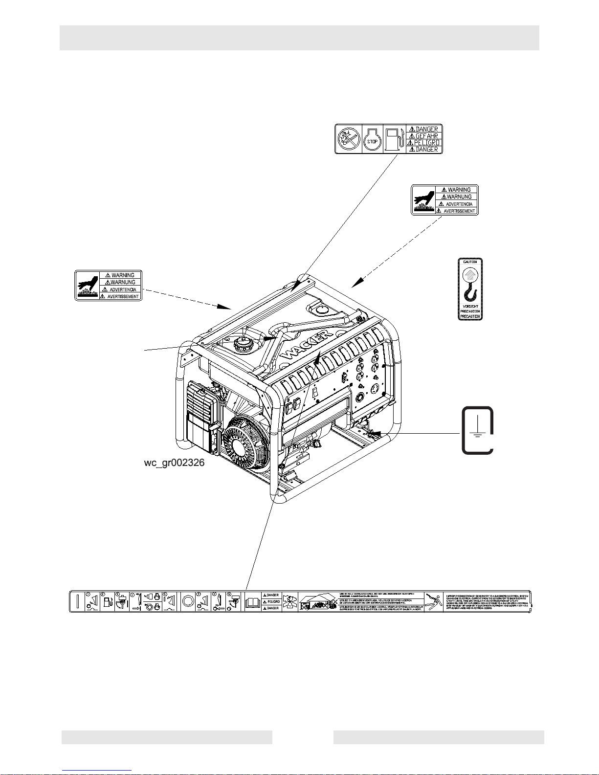
1.4 Label Locations
GND
88897

Safety Information GP Repair
wc_si000169gb.fm 10
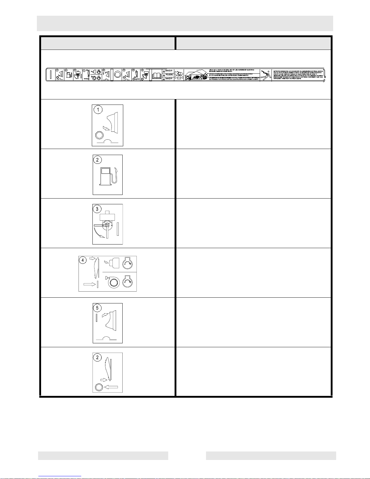
1.5 Safety and Operating Labels
Wacker machines use international pictorial labels where needed.
These labels are described below:
Label Meaning
WARNING!
Hot surface!
CAUTION!
Read and understand the supplied Operator’s
Manuals before operating this machine. Failure to do so increases the risk of injury to yourself or others.
CAUTION!
Lifting point
Electrical ground
GND
88897
GP Repair Safety Information
wc_si000169gb.fm 11
Close main circuit breaker.
Check the fuel level.
Open the fuel flow valve.
Press engine switch to ON position.
GPS — Press ignition switch.
GP — Pull the rewind starter.
Open main circuit breaker.
Press engine switch to OFF position.
Label Meaning
Safety Information GP Repair
wc_si000169gb.fm 12
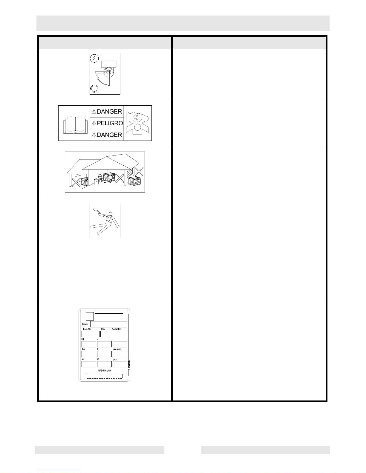
Close the fuel flow valve.
DANGER!
Asphyxiation hazard. Read the operator’s
manual for instructions.
Use in a well-ventilated area. Do not use
indoors or near open windows. Fumes can
cause death.
WARNING!
To reduce the risk of electrical shock, read the
operator’s manual. Improper connection of the
generator to a building’s electrical system can
allow electrical current from the generator to
backfeed into utility lines. This may result in
electrocution of utility workers, fire or explosion. Connections to a building’s electrical system must be made by a qualified electrician
and comply with all applicable laws and electrical codes.
A nameplate listing the model number, item
number, revision number, and serial number is
attached to each unit. Please record the information found on this plate so it will be available
should the nameplate become lost or damaged. When ordering parts or requesting service information, you will always be asked to
specify the model number, item number, revision number, and serial number of the unit.
Label Meaning
GP Repair Safety Information
wc_si000169gb.fm 13
This machine may be covered by one or more
patents.
DANGER!
No sparks, flames or burning objects near
machine.
Shut off the engine before refueling.
Label Meaning
Technical Data GP Repair
wc_td000169gb.fm 14
2. Technical Data
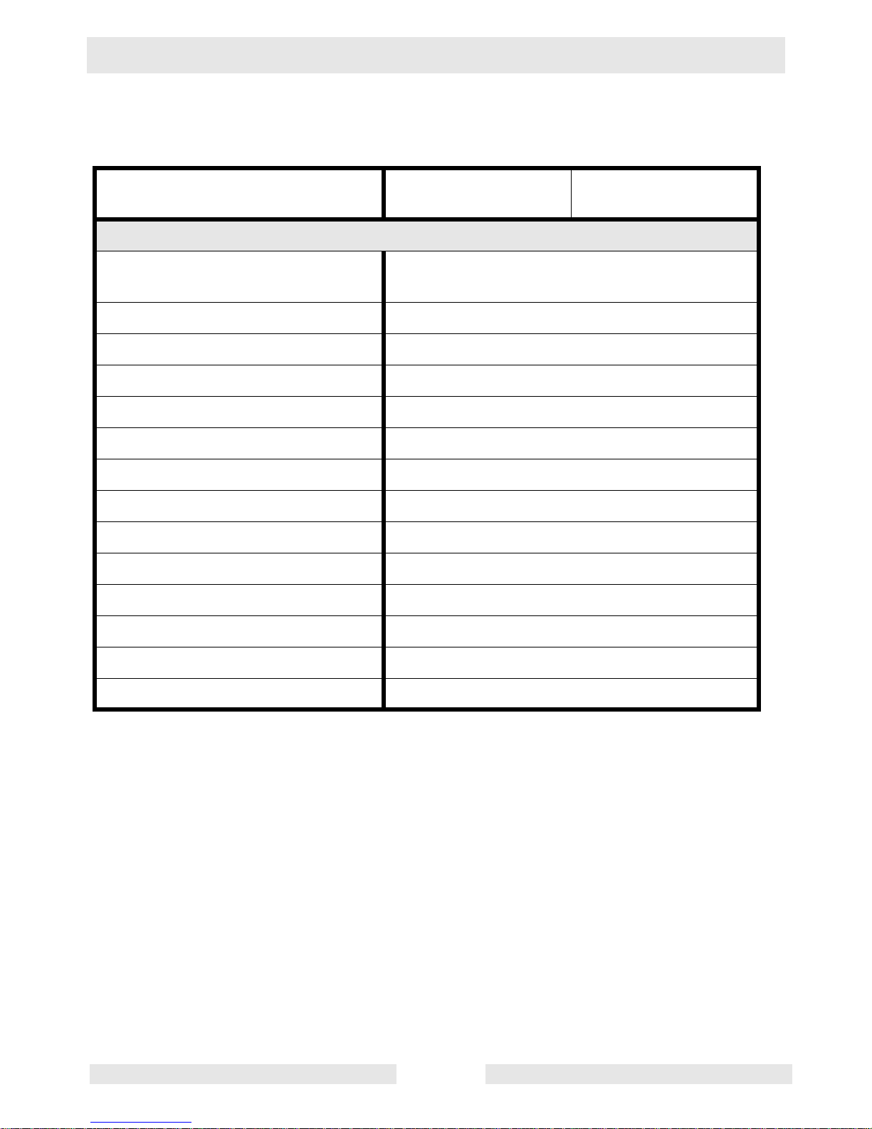
2.1 Generator—GP 2500A
Item No. GP 2500A
0620009
Generator
Maximum Output
W
2500
Continuous Output
W
2250
Type Single voltage, single phase,
Auto voltage regulator system
AC Voltages Available
volts
phase
120
1ø
Frequency
Hz
60
Power Factor 1.0
AC receptacles:
125V GFI duplex
125V duplex
amp
amp
20
20
Main Circuit Breaker
amp
20
L x W x H
mm (in.)
565 x 435 x 445 (22.3 x 17 x 17.5)
Weight (dry)
Kg (lbs.)
44.5 (98)
GP Repair Technical Data
wc_td000169gb.fm 15
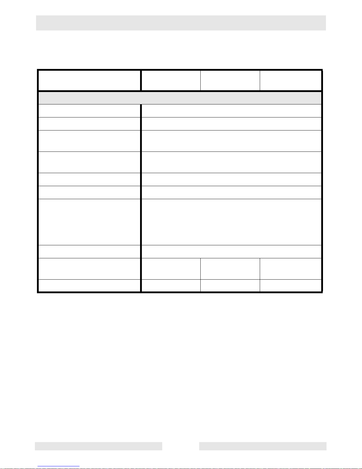
2.2 Engine—GP 2500A
Item No. GP 2500A
0620009
Engine
Engine Make Honda
Engine Model GX 160 K1VX
Rated Power
kW (Hp)
4.1 (5.5)
Spark Plug BPR6ES / W20EPR-U
Electrode Gap
mm (in.)
0.7–0.8 (0.028–0.031)
Operating Speed (Max.)
rpm
3600
Air Cleaner
type
Dry type with oil-wetted foam pre-cleaner
Engine Lubrication
oil grade
SAE 10W30 service class SF, SE, SD, or SC
Engine Oil Capacity
l (qts.)
0.6 (0.7)
Fuel
type
Regular unleaded gasoline
Fuel Tank Capacity
l (gal.)
12 (3)
Fuel Consumption
l (qts.)/hr.
1.7 (1.8)
Running Time - full load
hrs.
7
Technical Data GP Repair
wc_td000169gb.fm 16
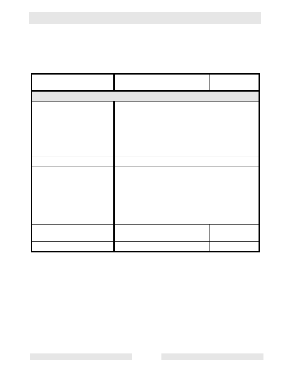
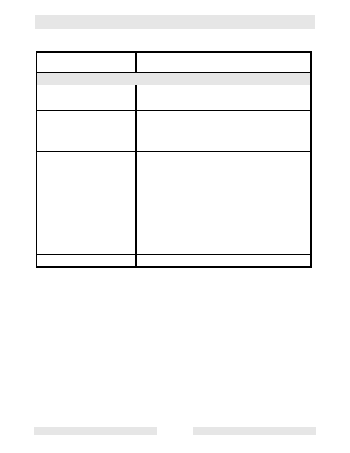
2.3 Generator—GP 3800A, GP 3800A CAN
Item No. GP 3800A
0620010
GP 3800A CAN
0620041
Generator
Maximum Output
W
3800
Continuous Output
W
3400
Type Dual voltage, single phase,
Auto voltage regulator system
AC Voltages Available
volts
phase
120 / 240
1ø
Frequency
Hz
60
Power Factor 1.0
AC receptacles:
125V GFI duplex
125V GFI duplex
125V twist-lock
125V/250V twist-lock
amp
amp
amp
amp
20
20
30
20
Main Circuit Breaker
amp
2-pole, 16 amp each pole
L x W x H
mm (in.)
685 x 530 x 520 (27 x 21 x 20.5)
Weight (dry)
Kg (lbs.)
73 (160)
GP Repair Technical Data
wc_td000169gb.fm 17
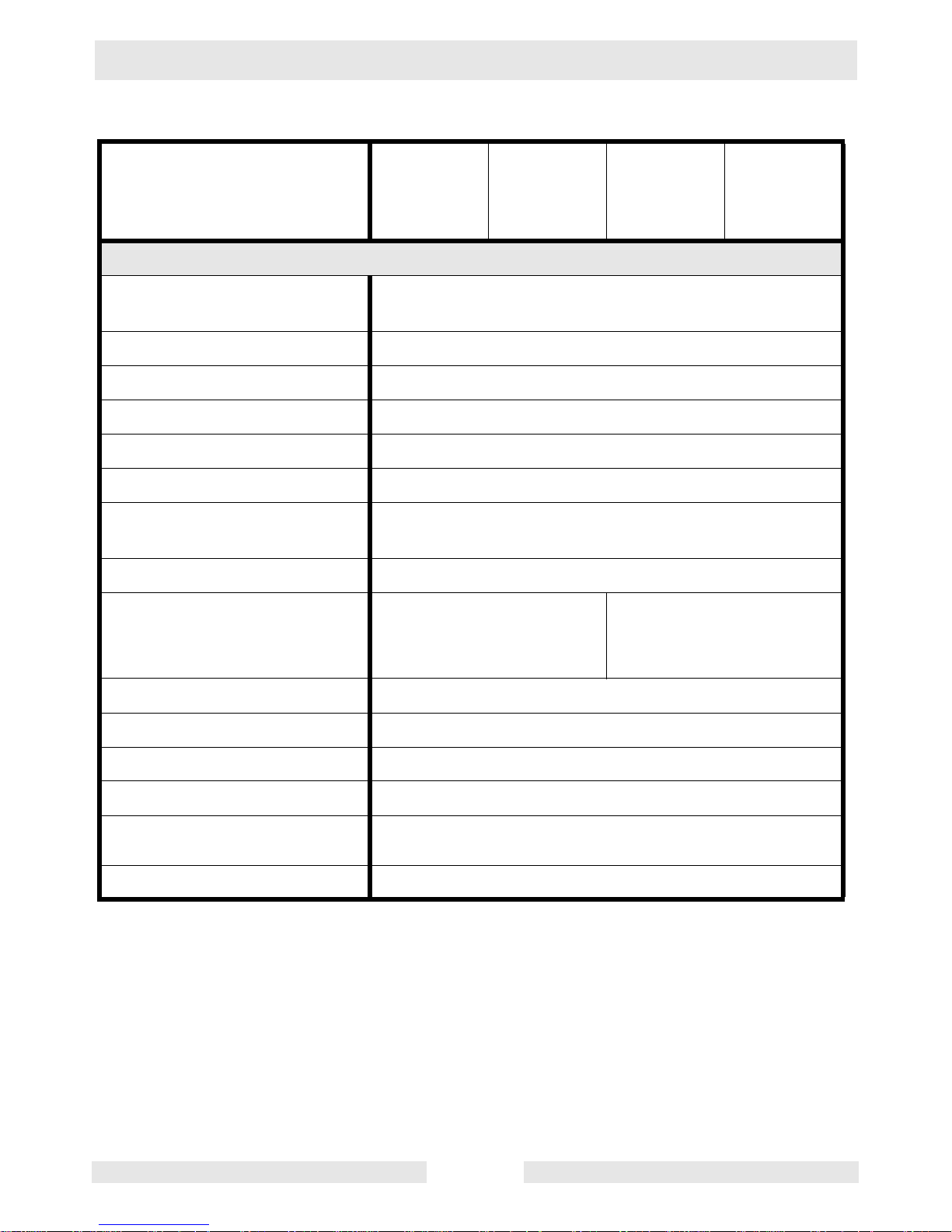
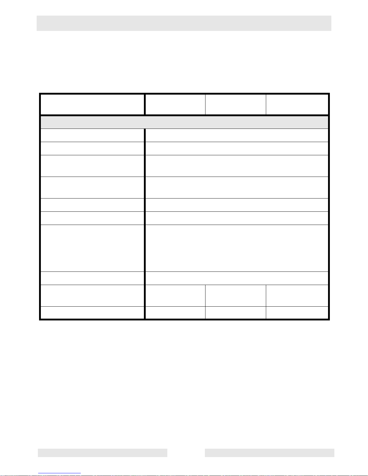
2.4 Engine—GP 3800A, GP 3800A CAN
Item No. GP 3800A
0620010
GP 3800A CAN
0620041
Engine
Engine Type Single cylinder, 4-cycle,
air-cooled, gasoline engine
Engine Make Honda
Engine Model GX 240
Rated Power
kW (Hp)
6 (8)
Spark Plug BPR6ES / W20EPR-U
Electrode Gap
mm (in.)
0.7–0.8 (0.028–0.031)
Operating Speed (max.)
rpm
3600
Air Cleaner
type
Dry type with oil-wetted foam pre-cleaner
Engine Lubrication
oil grade
SAE 10W30 service class SF, SE, SD or SC
Engine Oil Capacity
l (qts.)
1.1 (1.2)
Fuel
type
Regular unleaded gasoline
Fuel Tank Capacity
l (gal.)
19.5 (5.2)
Fuel Consumption
l (qts.)/hr.
2.4 (2.5)
Running Time
hrs.
8.2
Technical Data GP Repair
wc_td000169gb.fm 18
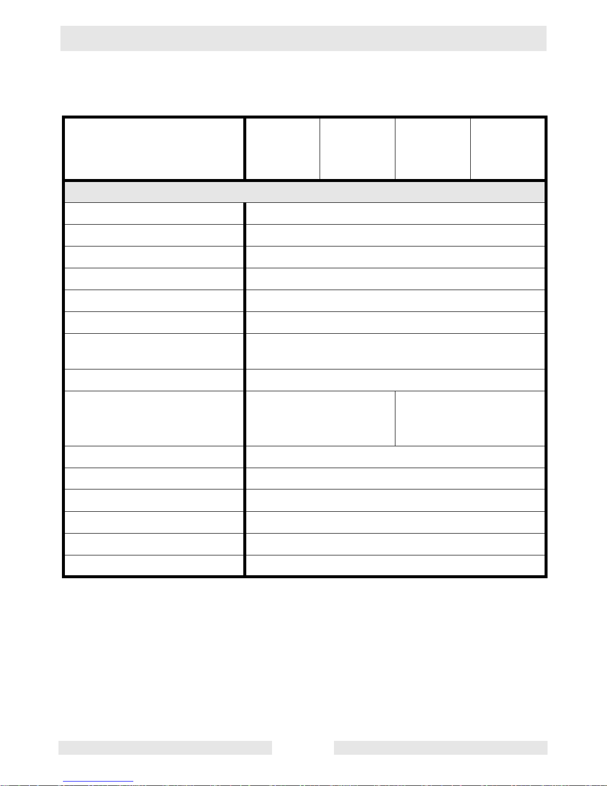
2.5 Generator—GP/GPS 5600A/5600A CAN
Item No. GP 5600A
0620011
GP 5600A
0620012
GPS 5600A
0620013
Generator
Maximum Output
W
5600
Continuous Output
W
5000
Type Dual voltage, single phase,
Auto voltage regulator system
AC Voltages
Available
volts
phase
120 / 240
1ø
Frequency
Hz
60
Power Factor 1.0
AC receptacles:
125V GFI duplex
125V GFI duplex
125V twist-lock
125V/250V twist-lock
amp
amp
amp
amp
20
20
30
30
Main Circuit Breaker
amp
2-pole, 23 amp each pole
L x W x H
mm
(in.)
685 x 530 x 520
(27 x 21 x 20.5)
1005 x 685 x 660
(39.5 x 27 x 26)
870 x 530 x 520
(34.3 x 21 x 20.5)
Weight (dry)
Kg (lbs.)
84 (186) 94 (208) 91 (201)
GP Repair Technical Data
wc_td000169gb.fm 19
Item No. GP 5600A CAN
0620042
GP 5600A CAN
0620043
GPS 5600A CAN
0620044
Generator
Maximum Output
W
5600
Continuous Output
W
5000
Type Dual voltage, single phase,
Auto voltage regulator system
AC Voltages
Available
volts
phase
120 / 240
1ø
Frequency
Hz
60
Power Factor 1.0
AC receptacles:
125V GFI duplex
125V GFI duplex
125V twist-lock
125V/250V twist-lock
amp
amp
amp
amp
20
20
30
30
Main Circuit Breaker
amp
2-pole, 23 amp each pole
L x W x H
mm
(in.)
685 x 530 x 520
(27 x 21 x 20.5)
1005 x 685 x 660
(39.5 x 27 x 26)
870 x 530 x 520
(34.3 x 21 x 20.5)
Weight (dry)
Kg (lbs.)
84 (186) 94 (208) 91 (201)
Technical Data GP Repair
wc_td000169gb.fm 20
2.6 Engine—GP/GPS 5600A/5600A CAN
Item No. GP 5600A
0620011
0620012
GP 5600A
CAN
0620042
0620043
GPS 5600A
0620013
GPS 5600A
CAN
0620044
Engine
Engine Type Single cylinder, 4-cycle,
air-cooled, gasoline engine
Engine Make Honda
Engine Model GX 340 K1
Rated Power
kW (Hp)
8.2 (11)
Spark Plug BPR6ES / W20EPR-U
Electrode Gap
mm (in.)
0.7–0.8 (0.028–0.031)
Operating Speed
(Max.)
rpm
3600
Air Cleaner
type
Dry type with oil-wetted foam pre-cleaner
Battery
type
rating
size (in.)
N/A
Y50-N18L-A
12V – 20 Amp-hour
8-
1
/8 x 3-9/16 x 6-7/
16
Engine Lubrication
oil grade
SAE 10W30 service class SF, SE, SD, or SC
Engine Oil Capacity
l (qts.)
1.1 (1.2)
Fuel
type
Regular unleaded gasoline
Fuel Tank Capacity
l (gal.)
19.5 (5.2)
Fuel Consumption
l (qts.)/
hr.
3.2 (3.4)
Running Time
hrs.
6

GP Repair Technical Data
wc_td000169gb.fm 21
Notes
Technical Data GP Repair
wc_td000169gb.fm 22
2.7 Generator—GP/GPS 6600A/6600A CAN
Item No. GP 6600A
0620014
GP 6600A
0620015
GPS 6600A
0620016
Generator
Maximum Output
W
6600
Continuous Output
W
6000
Type Dual voltage, single phase,
Auto voltage regulator system
AC Voltages
available
volts
phase
120 / 240
1ø
Frequency
Hz
60
Power Factor 1.0
AC receptacles:
125V GFI duplex
125V GFI duplex
125V twist-lock
125V/250V twist-lock
amp
amp
amp
amp
20
20
30
30
Main Circuit Breaker
amp
2-pole, 27 amp each pole
L x W x H
mm
(in.)
685 x 530 x 520
(27 x 21 x 20.5)
1005 x 685 x 660
(39.5 x 27 x 26)
870 x 530 x 520
(34.3 x 21 x 20.5)
Weight (dry)
Kg (lbs.)
87 (192)
96.6 (213)
94 (207.5)
GP Repair Technical Data
wc_td000169gb.fm 23
Item No. GP 6600A CAN
0620045
GP 6600A CAN
0620046
GPS 6600A CAN
0620047
Generator
Maximum Output
W
6600
Continuous Output
W
5500
Type Dual voltage, single phase,
Auto voltage regulator system
AC Voltages
available
volts
phase
120 / 240
1ø
Frequency
Hz
60
Power Factor 1.0
AC receptacles:
125V GFI duplex
125V GFI duplex
125V twist-lock
125V/250V twist-lock
amp
amp
amp
amp
20
20
30
30
Main Circuit Breaker
amp
2-pole, 27 amp each pole
L x W x H
mm
(in.)
685 x 530 x 520
(27 x 21 x 20.5)
1005 x 685 x 660
(39.5 x 27 x 26)
870 x 530 x 520
(34.3 x 21 x 20.5)
Weight (dry)
Kg (lbs.)
87 (192)
96.6 (213)
94 (207.5)
Technical Data GP Repair
wc_td000169gb.fm 24
2.8 Engine—GP/GPS 6600A/6600A CAN
Item No. GP 6600A
0620014
0620015
GP 6600A
CAN
0620045
0620046
GPS 6600A
0620016
GPS 6600A
CAN
0620047
Engine
Engine Type Single cylinder, 4-cycle, air-cooled, gasoline engine
Engine Make Honda
Engine Model GX 390
Rated Power
kW (Hp)
9.7 (13)
Spark Plug Champion RN10Y
Electrode Gap
mm (in.)
0.7–0.8 (0.028–0.031)
Operating Speed
(Max.)
rpm
3600
Air Cleaner
type
Dry type with oil-wetted foam pre-cleaner
Battery
type
rating
size (in.)
N/A
Y50-N18L-A
12V - 20 Amp-horo
8-
1
/8 x 3-9/16 x 6-7/
16
Engine Lubrication
oil grade
SAE 10W30 service class SF, SE, SD, or SC
Engine Oil Capacity
l (qts.)
1.1 (1.2)
Fuel
type
Regular unleaded gasoline
Fuel Tank Capacity
l (gal.)
19.5 (5.2)
Fuel Consumption
l (qts.)/hr.
3.9 (4.1)
Running Time
hrs.
5

GP Repair Operation
wc_tx000545gb.fm 25
3. Operation
3.1 Information Regarding Operation
The information regarding the operation of the machine included in this
manual is condensed. Refer to the Operator’s Manual for complete
operating instructions. Always read, understand, and follow the
procedures in the Operator’s Manual when operating the machine.
3.2 Determining Power Requirements
This generator is designed to operate single-phase, 60 Hz appliances
running at 120 VAC or 240 VAC. Check the nameplate or label
provided on tools and appliances to make sure their power
requirements match the power output of the generator.
Some appliances and tools require a surge of current when starting.
This means that the amount of power needed to initially start the
equipment is larger than the power required to keep it running. The
generator must be capable of supplying this “surge” current. Other
types of appliances require more power than is actually stated on their
nameplate.
The information in “Approximate Starting Power Requirements” is
offered only as a general guideline to help you in determining power
requirements for different types of equipment. Check with your nearest
Wacker Dealer, or contact the manufacturer or dealer of the tool or
appliance, with questions regarding its power requirements.
CAUTION: If a tool or appliance does not reach full speed within a few
seconds when switched on, turn it off immediately to avoid damage.
Approximate Starting Power Requirements:
• Incandescent lights and appliances such as irons and hot plates, which
use a resistive-type heating element, require the same wattage to start
and run as is stated on their nameplates.
• Fluorescent and mercury lamps require 1.2–2 times their stated
wattage to start.
• Electrical motors and many types of electrical tools often require a
large starting current. The amount of starting current depends on the
type of motor and its use.
• Most electrical tools require 1.2–3 times their stated wattage for
starting.
• Loads such as submersible pumps and air compressors require a very
large force to start. They need as much as 3–5 times the wattage
stated on the nameplate in order to start.

Operation GP Repair
wc_tx000545gb.fm 26
If the wattage is not given for a particular tool or appliance, it can be
calculated by multiplying its voltage and amperage requirements:
Single Phase: VOLTS x AMPS = WATTS
Three Phase: VOLTS x AMPS x 1.732 x 0.8 = WATTS
 Loading...