

Wacker Neuson G 85 Repair Manual
Repair Manual
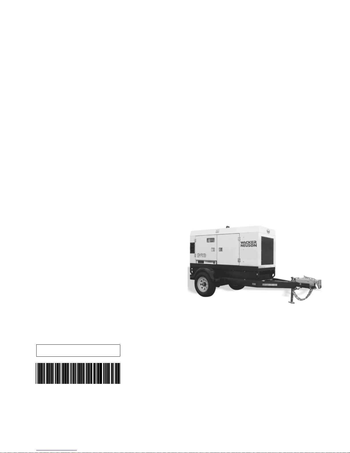
Mobile Generator
G 85
0171726en 004 0809
0171726EN

Copyright
notice
© Copyright 2009 by Wacker Neuson Corporation.
All rights, including copying and distribution rights, are reserved.
This publication may be photocopied by the original purchaser of the machine. Any
other type of reproduction is prohibited without express written permission from
Wacker Neuson Corporation.
Any type of reproduction or distribution not authorized by W acker Neuson Corp oration
represents an infringement of valid copyrights. Violators will be prosecuted.
T ra d emarks
Manufacturer
All trademarks referenced in this manual are the property of their respective owners.
Wacker Neuson Corporation
N92W15000 Anthony Avenue
Menomonee Falls, WI 53051 U.S.A.
Tel: (262) 255-0500 · Fax: (262) 255-0550 · Tel: (800) 770-0957

Mobile Generator Repair Foreword
This manual covers machines with Item Number:
0009369, 0009459, 0620003
Operating / Parts Information
You must be familiar with the operation of this machine before you
attempt to troubleshoot or repair it. Basic operating and maintenance
procedures are described in the Operator’s Manual supplied with the
machine. Keep a copy of the Operator’s Manual with the machine at all
times. Use the separate Parts Book supplied with the machine to order
replacement parts. If you are missing either of the documents, please
contact Wacker Neuson Corporation to order a replacement.
Damage caused by misuse or neglect of the unit should be brought to
the attention of the operator to prevent similar occurrences from
happening in the future.
This manual provides information and procedures to safely repair and
maintain the above Wacker Neuson model(s). For your own safety and
protection from injury, carefully read, understand, and observe all
instructions described in this manual. The information contained in this
manual is based on machines manufactured up to the time of
publication. Wacker Neuson Corporation reserves the right to change
any portion of this information without notice.
3

Foreword Mobile Generator Repair
CALIFORNIA
Proposition 65 Warning:
Diesel engine exhaust, some of its constituents, and certain vehicle
WARNING
components contain or emit chemicals known to the State of California
to cause cancer and birth defects or other reproductive harm.
Laws Pertaining to Spark Arresters
Notice: State Health Safety Codes and Public Resources Codes
specify that in certain locations spark arresters be used on internal
combustion engines that use hydrocarbon fuels. A spark arrester is a
device designed to prevent accidental discharge of sparks or flames
from the engine exhaust. Spark arresters are qualified and rated by
the United States Forest Service for this purpose.
In order to comply with local laws regarding spark arresters, consult
the engine distributor or the local Health and Safety Administrator.
All rights, especially copying and distribution rights, are reserved.
Copyright 2009 by Wacker Neuson Corporation
No part of this publication may be reproduced in any form or by any
means, electronic or mechanical, including photocopying, without
express written permission from Wacker Neuson Corporation.
Any type of reproduction or distribution not authorized by Wacker
Neuson Corporation represents an infringement of valid copyrights,
and violators will be prosecuted. We expressly reserve the right to
make technical modifications, even without due notice, which aim at
improving our machines or their safety standards.
4

MG Repair Table of Contents
1 Safety Information 9
1.1 Operating Safety ................................................................................ 10
1.2 Service Safety .................................................................................... 12
1.3 Operator Safety while using Internal Combustion Engines ................ 13
1.4 Towing Safety ..................................................................................... 14
1.5 Reporting Trailer Safety Defects ........................................................ 14
2 Theory of Operation 15
2.1 Basic Schematic ................................................................................. 15
2.2 Introduction ......................................................................................... 16
2.3 Terminology ........................................................................................ 18
3 Electrical Testing Techniques 22
3.1 Checking Continuity ........................................................................... 22
3.2 Checking Resistance .......................................................................... 22
3.3 Checking Voltage ............................................................................... 22
3.4 Probing ECM Plugs and Pins ............................................................. 23
4 ECM Background Information 24
4.1 ECM Handling Precaution .................................................................. 24
4.2 Normal Boot-up Sequence ................................................................. 25
4.3 Display Variables and Values ............................................................. 28
4.4 ECM Display Screens—Start Switch in Remote Position ................... 29
4.5 Additional Variables Monitored by the ECM ....................................... 30
4.6 Voltage Display Errors ........................................................................ 36
4.7 ECM Automatic Engine Shutdown Conditions ................................... 38
4.8 ECM Circuit Boards ............................................................................ 39
4.9 Control Wiring Numbering & Colors ................................................... 40
4.10 Removing and Installing the ECM ...................................................... 43
5

Table of Contents MG Repair
5 ECM/Sensor Troubleshooting 44
5.1 Checking Power to the ECM ...............................................................44
5.2 Checking Outgoing Power From the ECM ..........................................47
5.3 Checking Temperature Sender ...........................................................48
5.4 Fuel Sender Failure and Low Fuel Fault .............................................50
5.5 Calibrating ECM Voltage Display ........................................................51
5.6 Calibrating ECM AC Amperage Display ..............................................52
5.7 Calibrating ECM AC Frequency Display .............................................53
5.8 Calibrating ECM DC Display ...............................................................54
5.9 Checking the ECM CAN BUS Circuit ..................................................55
5.10 Checking the Main Circuit Breaker ......................................................56
5.11 ECM Plugs and Pins ...........................................................................57
6 John Deere Engines With ECU 59
6.1 John Deere Engines With ECU Background .......................................59
6.2 Locations of Engine Electrical Components ........................................60
6.3 Engine Electrical Components ............................................................61
7 Engine Starting Troubleshooting 62
7.1 Checking the Fuses .............................................................................62
7.2 Checking the Engine Control Module (ECM) ......................................63
7.3 Checking the Emergency Stop Switch ................................................64
7.4 Checking the Starter Relay .................................................................65
7.5 Checking the Starter Solenoid .............................................................66
7.6 Checking the Intake Heater Relay .......................................................67
7.7 Checking the Main Circuit Breaker ......................................................68
8 Output Voltage Troubleshooting 69
8.1 Checking the Emergency Stop Switch ................................................69
8.2 Checking the Lug Door Switch ............................................................70
8.3 Checking the Main Circuit Breaker ......................................................71
8.4 Checking the Voltage Adjusting Rheostat ...........................................72
8.5 Checking the Auxiliary Winding ...........................................................73
8.6 Checking the Exciter Stator .................................................................74
wc_br0171726en_004TOC.fm 6

MG Repair Table of Contents
8.7 Checking the AVR Sensing Wires ...................................................... 75
8.8 Flashing the Generator (checking the excitation system) .................. 76
8.9 Checking Stator Windings at the Lugs ............................................... 77
8.10 Checking the Rectifier Diodes—Thread-in Style ................................ 78
8.11 Checking the Rectifier Diodes—Solder-in Style ................................. 79
8.12 Checking the Main Rotor Winding ...................................................... 80
8.13 Checking the Exciter Rotor Winding ................................................... 81
8.14 Checking Stator Windings at the Voltage Selector Switch ................. 82
9 Disassembly/Assembly Procedures 84
9.1 Tools ................................................................................................... 84
9.2 Ordering Parts .................................................................................... 84
9.3 Reference Numbers ( ) ....................................................................... 84
9.4 Weight Block ...................................................................................... 84
9.5 Removing the Roof ............................................................................. 85
9.6 Preparing Unit for Generator Removal ............................................... 87
9.7 Replacing the Generator .................................................................... 89
9.8 Removing the AVR ............................................................................. 91
9.9 Installing the AVR ............................................................................... 92
9.10 Removing the Engine ......................................................................... 95
9.11 Installing the Engine ........................................................................... 97
9.12 Replacing the Fuel Tank .................................................................... 99
9.13 Replacing the Emergency Stop Switch (older) ................................. 101
9.14 Replacing the Emergency Stop Switch (newer) ............................... 103
9.15 Replacing the Diodes ....................................................................... 105
9.16 Replacing the Voltage Selector Switch (VSS) .................................. 107
9.17 G 50, G 70, G 85 VSS Wiring ........................................................... 109
10 Technical Data 110
10.1 Engine Data ...................................................................................... 110
10.2 Generator Data ................................................................................. 111
10.3 Trailer and Skid Data ........................................................................ 112
10.4 Dimensions ....................................................................................... 113
10.5 Engine Wiring Diagram—John Deere with ECU .............................. 114
10.6 ECU Wiring Diagram ...................................................................... 118
10.7 ECU Harness Connector .................................................................. 119
10.8 Generator Wiring Diagram ............................................................... 120
7

Table of Contents MG Repair
wc_br0171726en_004TOC.fm 8
G 85 Safety Information
G
1 Safety Information
This manual contains DANGER, WARNING, CAUTION, NOTICE, and
NOTE callouts which must be followed to reduce the possibility of
personal injury, damage to the equipment, or improper service.
This is the safety alert symbol. It is used to alert you to potential
personal injury hazards. Obey all safety messages that follow this
symbol to avoid possible injury or death.
DANGER indicates a hazardous situation which, if not avoided, will
result in death or serious injury.
DANGER
WARNING indicates a hazardous situation which, if not avoided, could
result in death or serious injury.
WARNING
CAUTION
WARNIN
CAUTION indicates a hazardous situation which, if not avoided, could
result in minor or moderate injury.
NOTICE: Used without the safety alert symbol, NOTICE indicates a
situation which, if not avoided, could result in property damage.
Note: Contains additional information important to a procedure.
Electrocution hazard!
Electrocution or severe electrical shock hazards are present
throughout the generator any time the engine is running! Read all
safety notes contained in this section before operating or servicing this
equipment.
No one except a trained electrician, familiar with this equipment,
should attempt repairs to the generator! Test procedures which require
that the generator be running must be performed using extreme
caution.
This machine is built with user safety in mind; however, like any
electrical device it can present serious hazards if improperly operated
and serviced. Follow instructions carefully! Should questions arise
during operation or service of this equipment, contact Wacker Neuson
Corporation.
wc_si000356gb.fm 9

Safety Information G 85
1.1 O perating Safety
Familiarity and proper training are required for the safe operation of the
machine. Machines operated improperly or by untrained personnel
can be hazardous. Read the operating instructions contained in this
WARNING
1.1.1 NEVER operate the generator when open containers of fuel, paint, or
1.1.2 NEVER place flammable material or liquids near the generator.
1.1.3 NEVER operate the generator, or tools attached to the generator, with
1.1.4 NEVER use worn electrical cords. Severe electrical shock and
1.1.5 NEVER operate the machine indoors unless exhaust fumes can be
manual and the engine manual, and familiarize yourself with the
location and proper use of all controls. Inexperienced operators should
receive instruction from someone familiar with the machine before
being allowed to operate it.
other flammable liquids are near.
wet hands.
equipment damage may result.
adequately ventilated.
1.1.6 NEVER overload the generator. The total amperage of the tools and
equipment attached to the generator must not exceed the load rating
of the generator.
1.1.7 NEVER allow untrained personnel to operate or service the generator.
The generator set should be set up by a certified electrician.
1.1.8 NEVER operate generator in standing water.
1.1.9 NEVER touch the hot engine, exhaust, or generator components.
Burns will result.
1.1.10 NEVER start a machine in need of repair.
1.1.11 Use the emergency stop button only in an actual emergency. DO NOT
restart the engine until the cause of the trouble has been determined
and fixed.
1.1.12 Wear hearing protection when operating equipment.
1.1.13 ALWAYS follow starting and stopping instructions described in this
manual. Know how to operate and stop generator before starting it.
1.1.14 ALWAYS make a walk-around inspection of the generator set before
starting it. Open side doors and visually inspect engine compartment
for obvious damage or the presence of foreign objects which might
affect operation.
1.1.15 ALWAYS keep the machine at least one meter (three feet) away from
structures, buildings, and other equipment during use.
1.1.16 Store the machine properly when it is not being used. The machine
should be stored in a clean, dry location out of the reach of children.
wc_si000356gb.fm 10

G 85 Safety Information
1.1.17 ALWAYS keep the area immediately surrounding and underneath the
machine clean, neat, and free of debris and combustible materials.
Make sure that the area overhead is clear of debris that could fall onto
or into the machine or exhaust compartment.
1.1.18 Be sure the machine is on a firm, level surface and will not tip, roll,
slide, or fall while operating.
1.1.19 ALWAYS remove all tools, cords, and other loose items from the
generator before starting it.
1.1.20 ALWAYS make certain the machine is well-grounded and securely
fastened to a good earthen ground per national and local regulations.
BACKFEED FROM THE GENERATOR INTO THE PUBLIC POWER
DISTRIBUTION SYSTEM CAN CAUSE SERIOUS INJURY OR
DEATH TO UTILITY WORKERS!
DANGER
Improper connection of generator to a building’s electrical system can
allow electrical current from the generator to backfeed into utility lines.
This may result in electrocution of utility workers, fire, or explosion.
Connections to a building’s electrical system must be made by a
qualified electrician and comply with all applicable laws and electrical
codes.
If connected to a building’s electrical system the generator must meet
the power, voltage, and frequency requirements of the equipment in
the building. Differences in power, voltage, and frequency
requirements may exist and improper connection may lead to
equipment damage, fire, and personal injury or death.
wc_si000356gb.fm 11

Safety Information G 85
1.2 S ervice Safety
A poorly maintained machine can become a safety hazard! In order
for the machine to operate safely and properly over a long period of
time, periodic maintenance and occasional repairs are necessary.
WARNING
1.2.1 NEVER perform even routine service (oil/filter changes, cleaning,
etc.) unless all electrical components are shut down. Before
servicing this machine, make sure the engine start switch is turned to
off “O”, the circuit breakers are open (off), the emergency stop switch
is closed (pushed in), and the negative terminal on battery is
disconnected. Attach a “DO NOT START” sign to the control panel.
This will notify everyone that the unit is being serviced and will reduce
the chance of someone inadvertently trying to start the unit. If the unit
is connected to a remote start or transfer switch, make sure the remote
switch is also off and tagged.
1.2.2 Ground Connection
The generator must be connected to a good earthen ground for
proper operating safety!
A central “equipment ground” is provided at the customer connection
lugs. This point is connected directly to the generator set base. All
other system grounds are connected to this central point. Ground the
generator in accordance with the standards defined in national, state,
and local regulations.
1.2.3 DO NOT attempt to open the radiator cap while the unit is running or
before the engine has cooled down. Severe burns may result!
1.2.4 DO NOT allow water to accumulate around the base of the machine.
If water is present, move the machine and allow the machine to dry
before servicing.
1.2.5 DO NOT service the machine if your clothing or skin is wet.
1.2.6 DO NOT allow untrained personnel to service this equipment. Only
trained electrical technicians should be allowed to service the electrical
components of this equipment.
1.2.7 Do not modify the machine without the express written approval of the
manufacturer.
1.2.8 DO NOT pressure wash the control panel, generator end, or any other
electrical components when cleaning the machine. Never allow water
to accumulate around the base of the generator set. If water is present,
DO NOT service!
1.2.9 ALWAYS replace the safety devices and guards after repairs and
maintenance.
1.2.10 ALWAYS let the engine cool before transporting or servicing the
machine.
wc_si000356gb.fm 12

G 85 Safety Information
1.2.11 ALWAYS remain aware of moving parts and keep hands, feet, and
loose clothing away from the moving parts of the machine.
1.2.12 ALWAYS replace all guards, fasten doors, and make sure all safety
devices operate properly after making repairs or servicing the
equipment.
1.2.13 ALWAYS keep hands, feet, and loose clothing away from the moving
parts on the generator and engine.
1.2.14 Keep the machine clean and labels legible. Replace all missing and
hard-to-read labels. Labels provide important operating instructions
and warn of dangers and hazards.
1.2.15 ALWAYS check all external fasteners at regular intervals.
1.2.16 ALWAYS make sure slings, chains, hooks, ramps, jacks, and other
types of lifting devices are attached securely and have enough weightbearing capacity to lift or hold the machine safely. Always remain
aware of the location of other people in the area when lifting the
machine.
1.3 Operator Safety while using Internal Combustion Engines
Internal combustion engines present special hazards during operation
and fueling. Read and follow the warning instructions in the engine
owner’s manual and the safety guidelines below. Failure to follow the
WARNING
1.3.1 Do not run engine indoors or in an area with poor ventilation unless
1.3.2 Do not fill or drain the fuel tank near an open flame, while smoking, or
1.3.3 Do not refuel a hot or running engine.
1.3.4 Refill the fuel tank in a well-ventilated area.
1.3.5 Do not touch or lean against hot exhaust pipes.
1.3.6 Replace the fuel tank cap after refueling.
1.3.7 Do not start the engine if fuel has spilled or a fuel odor is present. Move
1.3.8 Do not remove the radiator cap when the engine is running or hot. The
warnings and safety standards could result in severe injury or death.
exhaust hoses are used.
while the engine is running.
the generator away from the spill and wipe the generator dry before
starting.
radiator fluid is hot and under pressure and may cause severe burns!
wc_si000356gb.fm 13

Safety Information G 85
1.4 Towing Safety
Towing a large trailer requires special care. Both the trailer and vehicle
must be in good condition and securely fastened to each other to
reduce the possibility of an accident.
WARNING
1.4.1 ALWAYS check that the hitch and coupling on the vehicle are rated
equal to, or greater than, the trailer’s “gross vehicle weight rating”
(GVWR).
1.4.2 ALWAYS inspect the hitch and coupling for wear or damage. DO NOT
tow the trailer using defective parts.
1.4.3 ALWAYS make sure the coupling is securely fastened to the vehicle.
1.4.4 ALWAYS check the tires on the trailer for tread wear, inflation, and
condition. Replace worn tires.
1.4.5 ALWAYS connect the safety chains.
1.4.6 ALWAYS connect the breakaway cable safety hook to the bumper or
rear of the vehicle. DO NOT attach it to the hitch.
1.4.7 ALWAYS test the surge brakes on the trailer and the brakes on the
vehicle that will be used for towing.
1.4.8 ALWAYS make sure directional and trailer lights are connected and
working properly.
1.4.9 ALWAYS check that the lug nuts holding the wheels are tight and that
none are missing.
1.5 Reporting Trailer Safety Defects
If you believe your trailer has a defect which could cause a crash or
could cause injury or death, you should immediately inform the
National Highway Traffic Safety Administration (NHTSA) in addition to
notifying Wacker Neuson Corporation.
If NHTSA receives similar complaints, it may open an investigation;
and if it finds that a safety defect exists in a group of vehicles, it may
order a recall and remedy campaign. However, NHTSA cannot
become involved in individual problems between you, your dealer, or
Wacker Neuson Corporation.
To contact NHTSA, you may either contact the Auto Safety Hotline tollfree at 1-800-424-9393 (or 366-0129 in Washington DC area),
www.nhtsa.com, or write to NHTSA, U.S. Department of
Transportation, 400 7th Street SW, (NSA-11), Washington, DC 20590.
You can also obtain other information about motor vehicle safety from
the Auto Safety Hotline.
wc_si000356gb.fm 14
Mobile Generator Theory of Operation
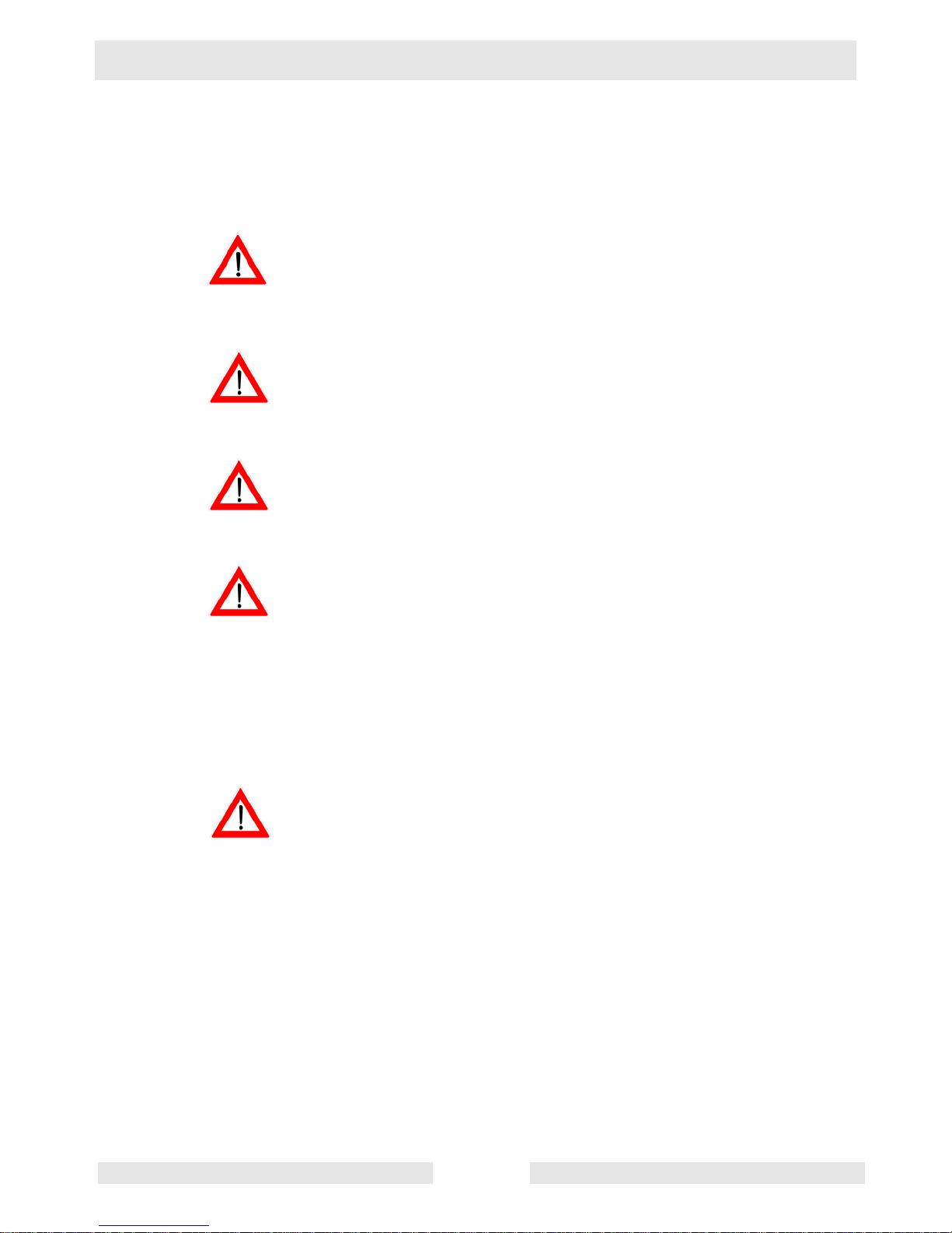
2 Theory of Operation
2.1 Basic Schematic
l
3-Phase AC out
c
T1
b
d
DC in
T2
T3
L1
h
a
LY
++–
DC out (exciter field)
BRGYL
BW
5C
j
AC in
n/a n/a
5B 7 5A 6 5 4A 4 3A 3 2 1
AMP HZ STAB
VOLT
e
–
L/W LR
k
AC sensing
g
i
T10
T9
T12
T11
T4
T8
f
Ref. Component Ref. Component
T7
T6
T5
L2
3-Phase
AC output
L3
N
GND
wc_gr003643
a Exciter stator winding g Automatic Voltage Regulator
b Rotor assembly h Main circuit breaker
c Exciter rotor winding i Auxiliary winding
d Rotating rectifier (diodes) j Voltage adjusting rheostat
e Main rotor winding k Lug door switch
f Main stator windings l Stator assembly
wc_tx001077gb.fm 15
(AVR)

Theory of Operation Mobile Generator
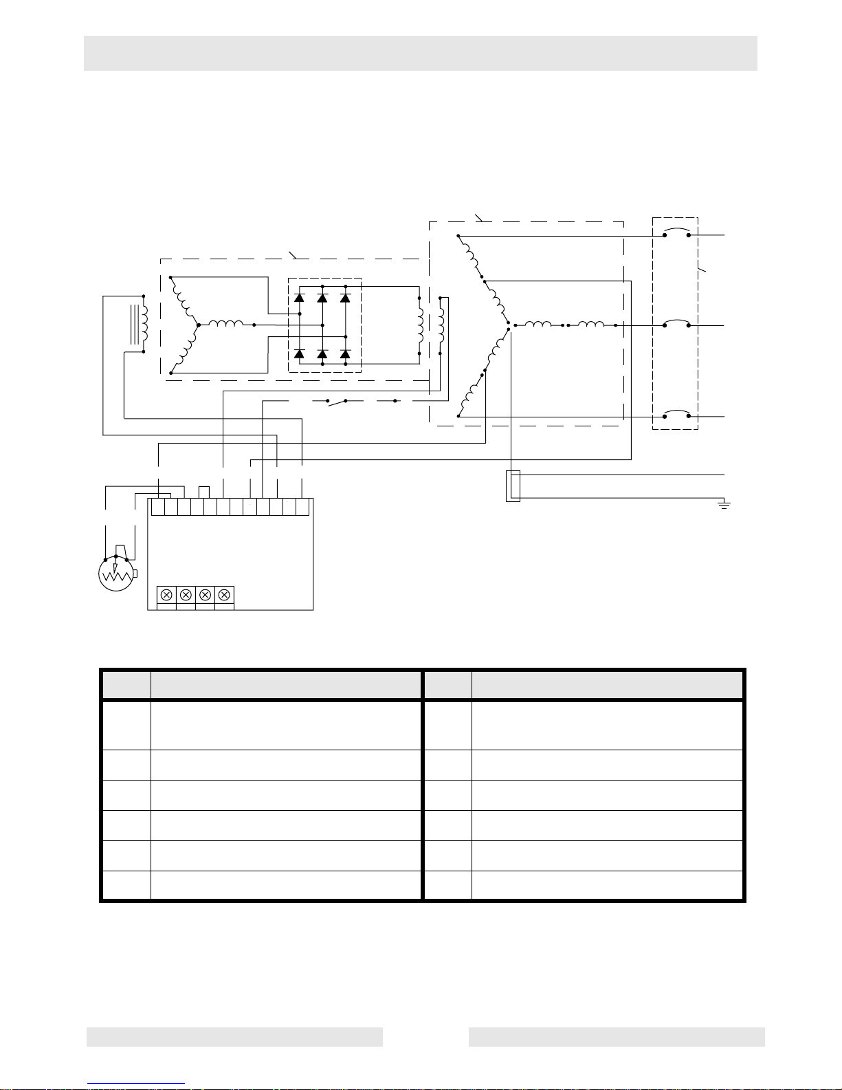
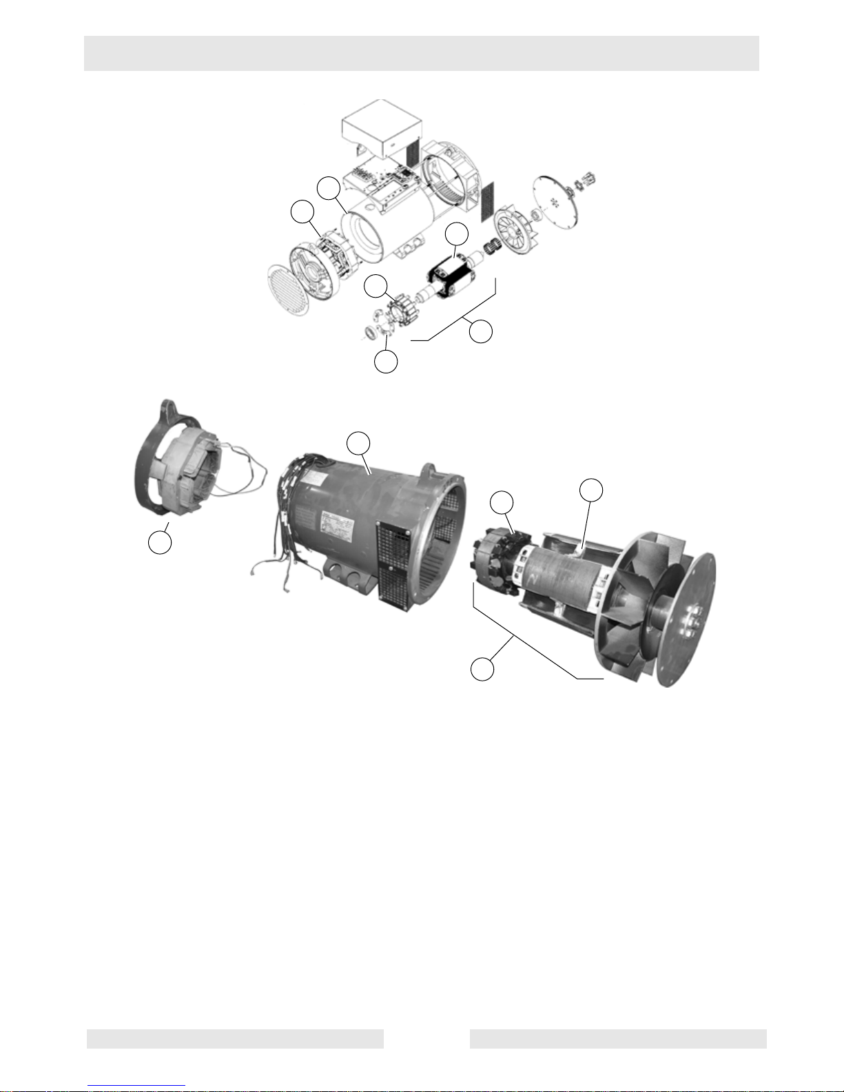
2.2 Introduction
See Graphic: wc_gr003303
A generator set is a transducer, which means it converts energy from
one form (heat) into another (electrical). The two main components of
a generator set are the prime mover (engine) and the generator
assembly. The engine converts heat into rotating mechanical energy
which is then converted by the generator assembly into electrical
energy. The generator does so through the principle of
electromagnetic induction. This principle states that when a coil of wire
(also known as a winding) is passed through a magnetic field, a
voltage is induced in the winding. The amount of voltage depends on
three factors: 1) the speed of the coil cutting through the magnetic field
(it does not matter which is moving—either the magnetic field or the
winding); 2) the strength of the magnetic field; and 3) the amount of
turns of wire in the winding. The principle also works in reverse; that is,
if voltage and current are present in a coil of wire, a magnetic field is
produced. It is important to understand this basic theory to understand
how the generator functions.
The typical brushless generator assembly consists of a stator
(stationary element), a rotor (rotating element), a voltage regulator
(voltage control device), and a rectifier assembly (current control
device). The rotor can function as either the magnetic field or the
winding. Likewise, the stator can function as either the magnetic field
or the winding, depending on the application. In Wacker Neuson
generators there are two stators (a and b) and a single rotor assembly
(c). The rotor assembly is made up of two halves—the exciter (d) and
the main (e). Three windings make up the exciter half and a single
winding makes up the main rotor half. There are three distinct stator
windings—the exciter, the main, and the auxiliary. The exciter stator
winding (a) is a stand-alone winding. The main and auxiliary windings
are housed within the large stator housing (b).
The exciter stator is the generator’s source of residual magnetism. As
the engine spins, the exciter rotor portion of the rotor assembly spins
inside the exciter stator, an AC voltage is induced in the exciter rotor.
This AC voltage is rectified into DC by the diodes (f) connected to the
rotor assembly. The DC voltage flows through the main rotor winding,
creating a magnetic field. Voltage is then induced in the main stator
windings and the auxiliary winding. The voltage induced in the main
stator windings provides the voltage to the lugs and the receptacles.
The voltage induced in the auxiliary winding is used to power the
voltage regulator.
wc_tx001077gb.fm 16
Mobile Generator Theory of Operation
b
a
e
d
c
f
b
d
e
a
c
wc_gr003303
wc_tx001077gb.fm 17

Theory of Operation Mobile Generator
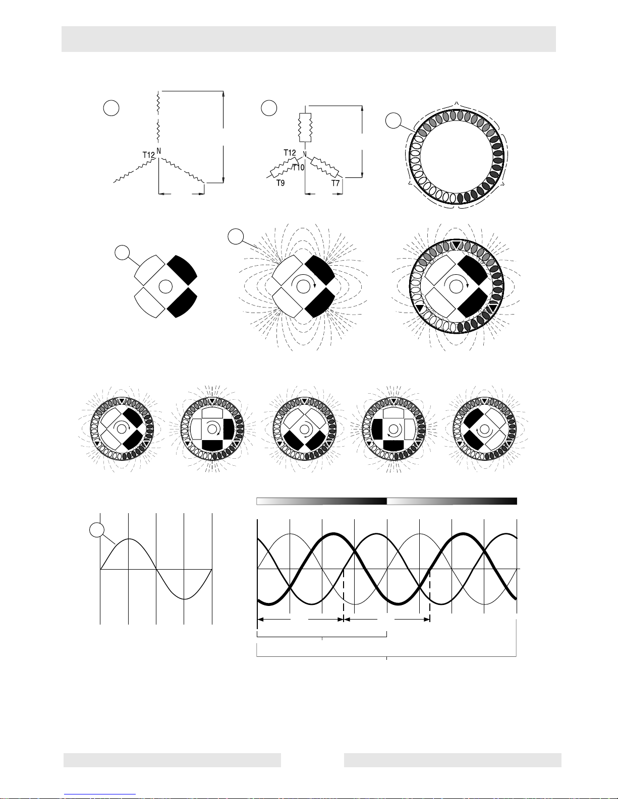
2.3 Terminology
See Graphic: wc_gr003315
To understand the terms “phase”, “leg”, “line-to-line”, and “line-to-
neutral”, review the following information.
• The main stator (a) consists of three separate groups of windings.
These groups of windings are referred to as legs. The legs are
labeled L1, L2, and L3. Each leg includes two individual windings. The
ends of these windings are labeled T1, T2, T3, and so on, up to T12.
• Each individual winding has the same resistance (0.2 Ohms). The
voltage selector s witch determines how the windings are connected—
in series or parallel. In series, the total voltage of a leg is equal to the
sum of the voltages induced across both windings. In parallel, the
total voltage of a leg is equal to the voltage induced across either
winding (only one).
• Each leg (L1, L2, and L3) is physically 120° from each other.
• The main rotor (b) functions as a rotating magnetic field. It has four
poles, two of which function as North and the other two as South.
• “Flux” is a term used to describe the amount of magnetic field in a
given area. The term “lines of flux” refers to the direction of the attraction of the magnetic fields—North to South. The point where these
lines of flux are closest to 90° is the point where the magnetic field is
the strongest, i.e., at either pole. The lines of flux (c) of the main
rotor’s magnetic field are as shown. When the windings of the stator
cut these lines of flux, voltage is induced in them. The amount of
induced voltage is greatest at the position where the stator winding is
perpendicular to the lines of flux, i.e., when the rotor is in such a position that the windings of a leg are centered over one of the four magnetic poles.
• When the two windings of each leg are connected in series, this is the
high-wye configuration (e). The v oltage induced in this configuration is
277V per leg. When the two windings of each leg are wired in parallel,
this is the low-wye configuration (f). The voltage induced in this configuration is 139V per leg. (It is adjusted to a usable 120V by the control panel rheostat.)
• The amount of voltage induced in each leg over time can be graphed.
This graph yields a sine wave (d). It represents the repeating event
(cycle) of the induced positive voltage of the North pole followed by
the induced negative voltage of the South pole. Since the rotor has
four magnetic poles, this cycle occurs twice per re v olution of the rotor.
• The engine spins the rotor at 1800 rpm which equals 30 revolutions
per second (rps) (1800 ÷ 60 = 30). The number of revolutions per second multiplied by the cycles per revolution (cpr) equals the cycles per
second (Hertz). Thus, 30 rps x 2 cpr = 60 Hz.
wc_tx001077gb.fm 18
Mobile Generator Theory of Operation
a
e
e
ye
6
5
8
9
0
3
(480V)
(208V)
3
5
8
6
(
)
(
)
3
3
S1
High Wy
L
N1
S1
L3
Low W
T
-
T
T1
T
T
-
277V
T
L
T
-
T
-
120V
T
L3
T
c
L1
L2
L1
b
N1
L3
S2
N2
180˚45˚
N2
S2
L2
L1
S1
N1
L2
L1
0˚
S2
N1
S1
S2
N2
L2
L3
N2
L1
N1
N2
S2
L2
S1
S1
L3
N1
N2
S1
90˚
L1
N1
S2
S2
N2
L2
L3
N2
135˚
L1
S1
L3
S1
N1
S2
L2
0˚ 45˚ 90˚ 135˚ 180˚
d
L1
wc_tx001077gb.fm 19
N1–S1 N2–S2
45˚ 90˚ 135˚ 180˚0˚ 225˚ 270˚ 315˚ 360˚
L2
L1
L3
120˚ 120˚
1 Hz
1 Rev
wc_gr003315
Theory of Operation Mobile Generator
• Since the legs are mechanically 120° apart, as the rotor spins, time
elapses between the moment when one leg reaches its largest voltage potential and the moment when the next leg reaches its largest
voltage potential. Thus, no two legs reach their largest voltage potential at the same moment in time, and their corresponding sine waves
are 120° apart. In other words, the voltages induced in each leg are
120° out of phase with each other.
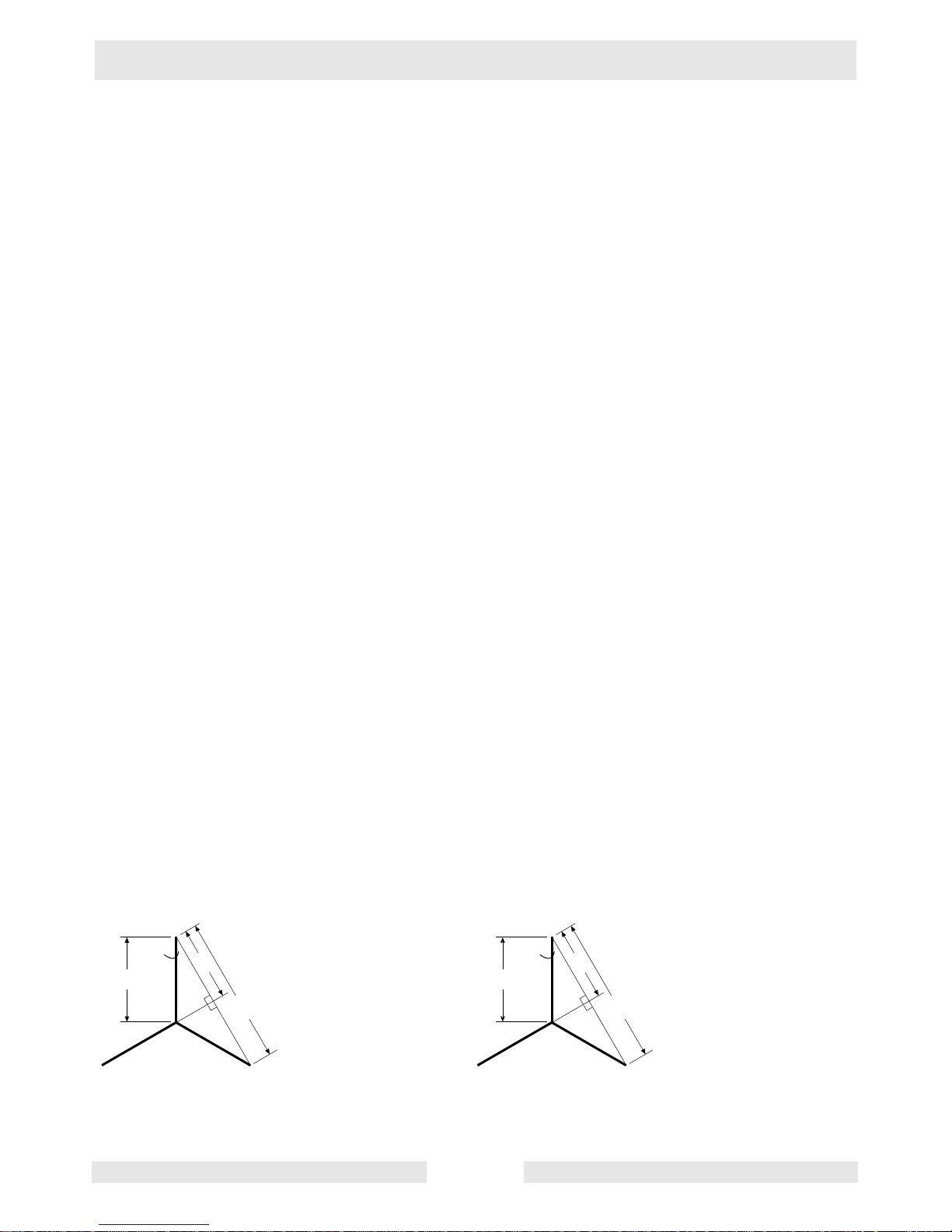
• Although the largest amount of voltage induced in any single leg in
the high-wye configuration is 277V, the voltage induced in a second
leg (either of the other two legs) at that same moment can be tapped
and combined with the 277V of the first leg to create the maximum
voltage available from the generator. The amount of voltage in the
second leg is less than its largest potential because of the position of
the rotor’s magnetic field—it is less than perpendicular to the second
leg. The amount of voltage induced is approximately 73% (203V) of
its potential (see graphic wc_gr003317). Thus, 277V + 203V = 480V,
which is the maximum voltage available from the generator. In the
low-wye configuration, the largest usable voltage potential in any leg
is 120V; adding the 73% of any second leg (88V), yields the maximum voltage potential for the low-wye configuration—208V.
277
30˚
120˚
120˚
60˚
60˚
• Any measurement between the end of a leg and neutral is know as
line-to-neutral (L-N) voltage. Any measurement between the end of
one leg to the end of another leg is known as line-to-line (L-L) voltage.
Any combination of L-N or L-L voltages are 120° out of phase with
each other. For example, L1–N is out of phase with L2–N; L2–N with
L3–N; L3–N with L1–N. Likewise, L1–L2 is out of phase with L2–L3;
L2–L3 with L3–L1; and L2–L3 with L1–L2.
• A three-phase event exists when a three-phase load is attached to the
generator. The three-phase load uses both the voltage and current
from each phase produced by the generator simultaneously. Positive
current produced by the voltage from each leg flo ws to corresponding
legs of the load.
Sine 60 = 0.866
Sine 60 = a/277
a
2(a)
0.866 = a/277
277 x 0.866 = (a/277) x 277
240 = a
2(a) = 480
480 – 277 = 203
203/277 = 0.73 = 73%
120
30˚
120˚
120˚
60˚
a
2(a)
60˚
Sine 60 = 0.866
Sine 60 = a/120
0.866 = a/120
120 x 0.866 = (a/120) x 120
104 = a
2(a) = 208
208 – 120 = 88
88/120 = 0.73 = 73%
wc_tx001077gb.fm 20
wc_gr003317
Mobile Generator Theory of Operation
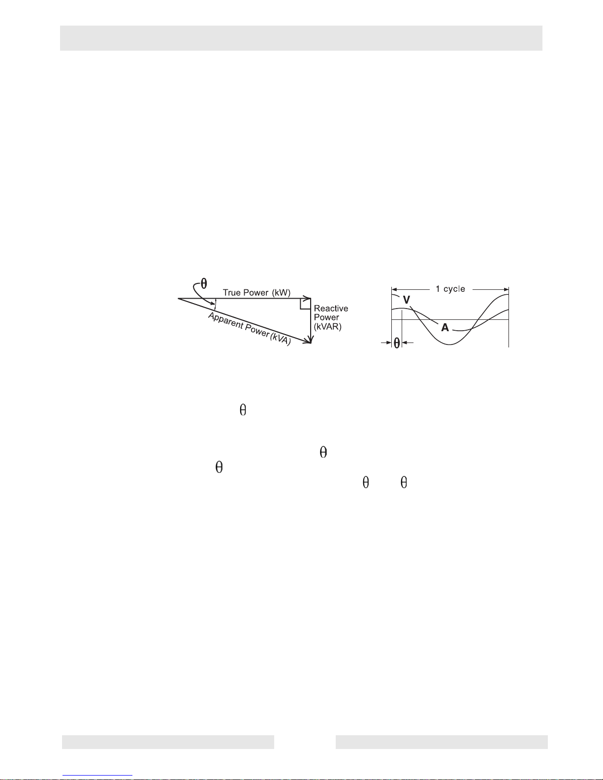
• Wacker Neuson generators are designed to accommodate various
loads and multiple power factors. Power factor is the relationship
between power supplied to the load (ref erred to as apparent power in
kVA) and true power (pow er used by the load (kW). It is expressed
mathematically by the equation: power f actor = true powe r ÷ apparent
power. The power factor is determined by the type of load—inductive
or resistive. In resistive loads, such as heaters, the power factor is
typically 1. In inductive loads, such as motors and tr ansformers, the
power factor is always less than 1. In inductive loads, a portion of the
supplied power is converted to a magnetic field and not used by the
load. This unused power is known as reactiv e po wer. The relationship
between apparent power, true power, and reactive pow er is illustrated
in the power right triangle below.
Reactive pow er and true power are always represented 90° from
each other. In the power right triangle, the angle formed by the hypotenuse (apparent power) and the adjacent side (true power) is referred
to as theta ( ). Theta is derived from the separation in the sine w a v es
of voltage and current. In inductive circuits, current lags the voltage
due to such factors as coil length, coil material, and frequency. From
trigonometry, the cosine of = adjacent side ÷ hypotenuse. Since
cosine and pow e r factor are calculated in the same manner, power
factor is often referred to as cosine (cos ).
• Single-phase receptacles are tapped off the legs in a manner that
keeps the generator balanced. That is, v oltage supplies to the v arious
single-phase outlets originate from different legs of the generator (L1
and L3), not from the same leg. When tapping single-phase loads
from the lugs, care must be taken so that the generator does not
become unbalanced. Attach equal loads to each leg if you are running
the generator in this manner.
wc_tx001077gb.fm 21

Electrical Testing Techniques Mobile Generator
3 Electrical Testing Techniques
3.1 Checking Continuity
Conduct continuity tests when the engine is shut down.
When checking continuity, use the Ohm setting on your multimeter.
Place a lead of the multimeter on one end of the wiring or component
and the other lead on the opposite end. If your meter reads “OL” or
“OPEN”, there is no continuity and the wiring or component must be
repaired or replaced.
Note: Some multimeters also have an audio signal setting for
determining continuity. This setting may also be used.
• If your meter reads less than 1.0 Ohm, or the audio signal
sounds, the wiring or component has continuity and should be
OK.
• If your meter reads more than 1.0 Ohm, the wiring is faulty and
must be repaired or replaced.
3.2 C hecking Resistance
Conduct resistance checks when the engine is shut down.
Use the Ohm setting on your multimeter.
Conduct resistance checks when the machine is as close to 21°C
(70°F) as possible. Higher temperatures can affect resistance values.
Most digital multimeters have some internal resistance. To obtain your
multimeter’s internal resistance, simply cross the two leads of your
multimeter and read the display. When conducting a resistance check,
subtract your multimeter’s internal resistance from the value you
measure to obtain the true resistance of the component you are
checking.
3.3 Checking Voltage
Conduct voltage checks when the engine is running.
Use the Volt setting on your multimeter. To prevent damage to your
instrument, start with the highest scale available on your multimeter.
Adjust to a lower scale as readings dictate.
Use extreme caution when checking voltage to reduce the risk of
electric shock.
22 wc_tx000699gb.fm
Mobile Generator Electrical Testing Techniques
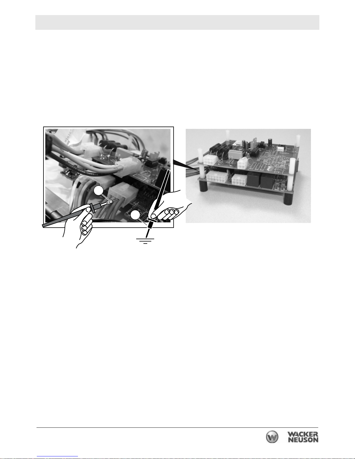
3.4 Probing ECM Plugs and Pins
See Graphic: wc_gr002926
To measure the voltage at an ECM pin, attach an appropriate
extension (a) to the positive probe on your multimeter. Slide the
positive probe into the plug along the wire of the pin to be tested. Use
care when testing this way so you don’t damage the wire, plug, or
ECM. Find a suitable ground on the machine’s frame for the negative
probe (b) of your multimeter.
6
5
4
3
2
1
12
11
10
9
8
6
5
4
3
2
a
4
3
2
1
7
8
7
6
1
5
4
3
2
1
b
wc_gr002926
wc_tx000699gb.fm 23
ECM Background Information Mobile Generator
4 ECM Background Information
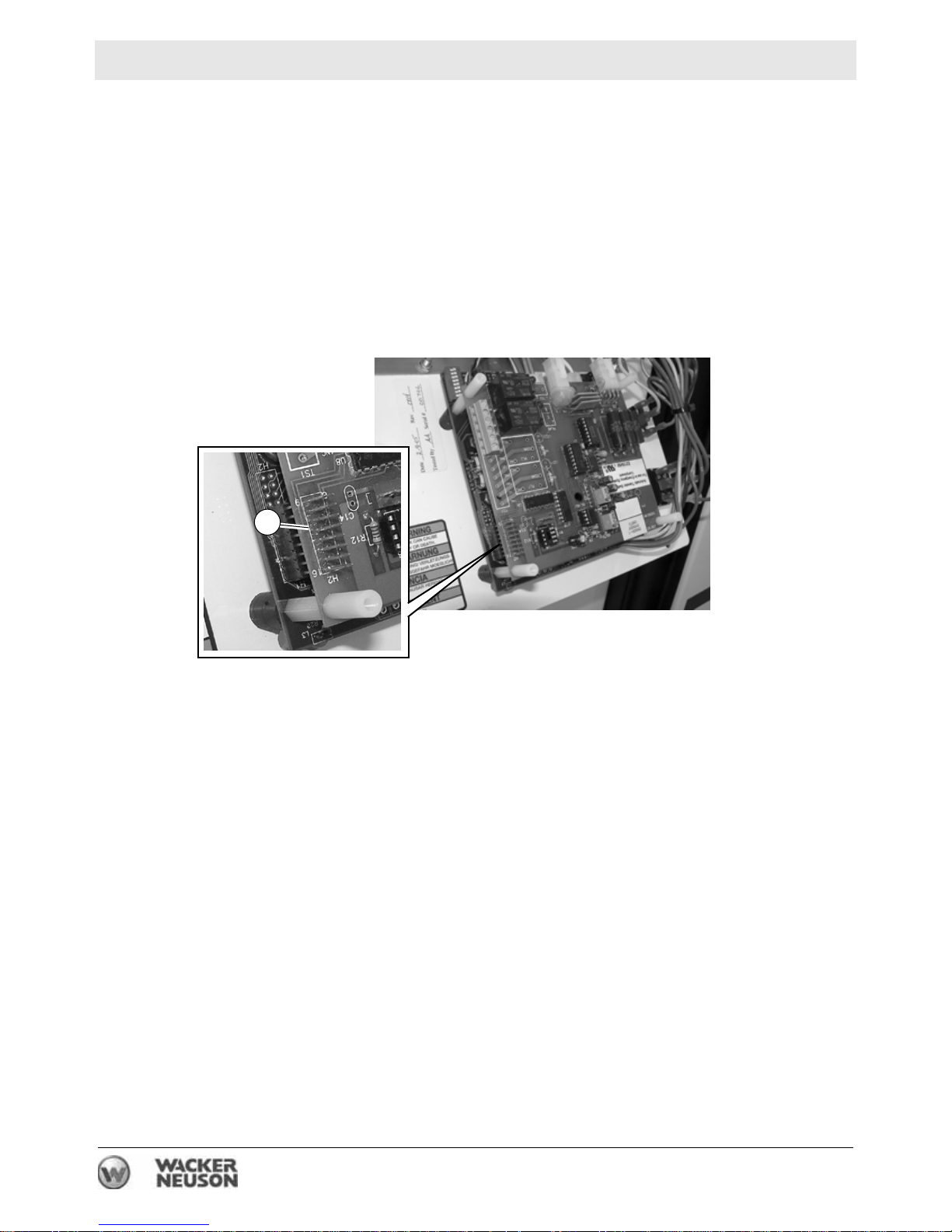
4.1 ECM Handling Precaution
See Graphic:wc_gr003355
NOTICE: Use care when working on or around the ECM. The ECM
may be damaged or it may malfunction if it is accidentally hit by your
hand or a tool. Do not touch the pins (a) of the ECM because the AC
board of the ECM may malfunction.
a
wc_gr003355
24 wc_tx000713gb.fm
Mobile Generator ECM Background Information
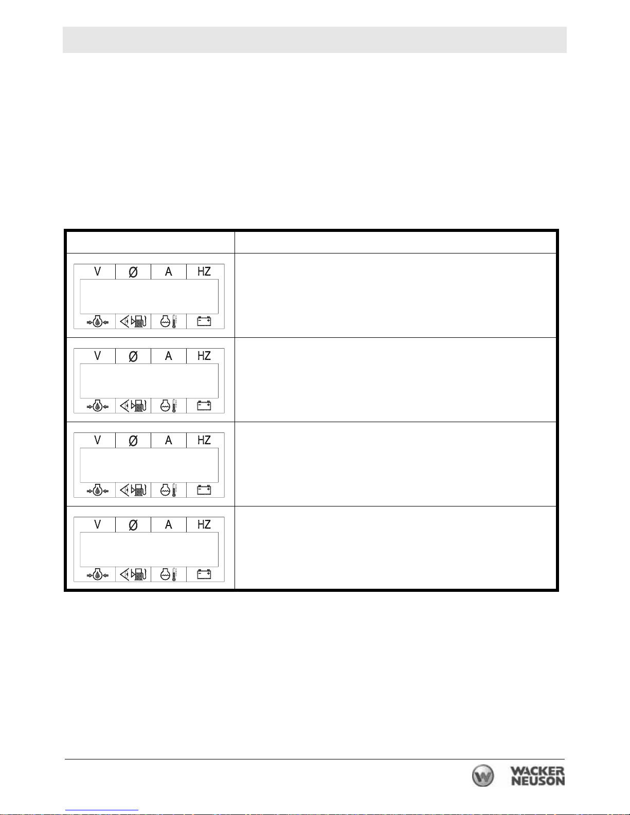
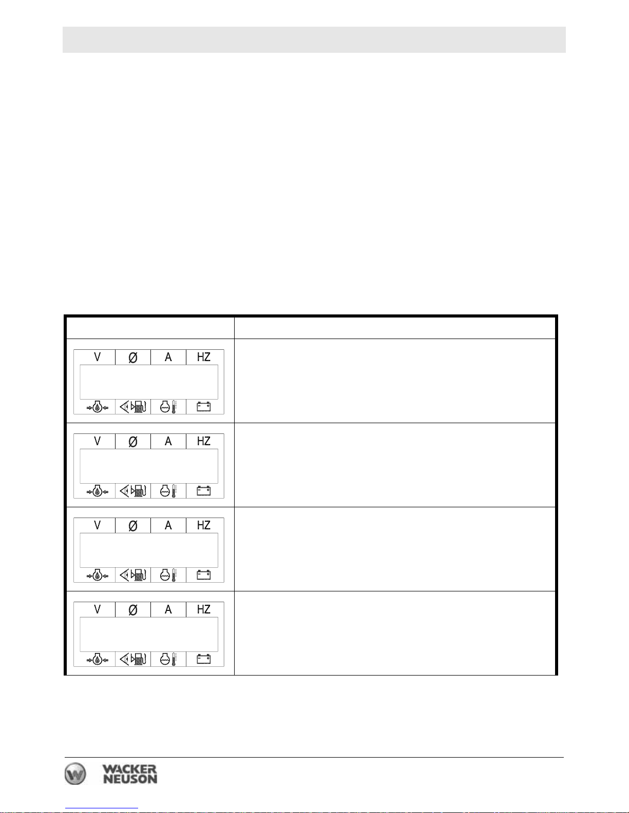
4.2 Normal Boot-up Sequence
During the boot-up sequence, the ECM scrolls through several
screens before it settles into displaying the run screen. There are two
different boot-up sequences depending on size of the generator and
options included on the generator. Both of the boot-up sequences are
listed below. When checking the boot-up sequence of your generator,
be sure you are checking the one that matches your generator.
G 25, G 50, G 70, G 85 (9310)
ECM Display Description
Start of the boot-up sequence. The ECM shows that the
glow plugs are on. The LED near the stop icon also illu-
Glow Plugs
On
minates. Note that the glow plugs are only on during the
first of the three starting cycles.
Starting Engine
Time to Service
250
480 P2 0 61.5
71 75% 87 12.7
The ECM displays this screen when the starter is cranking the engine.
The ECM displays the countdown time , in hours, until the
next scheduled service. The timer starts at 250 and
counts down to 0.
At this point, the ECM displays the running values of the
generator.
Note: The ECM display scrolls through each phase (P1,
P2, P3) if in the 3-phase mode, or L1, L3, and L1 + L3 if
in the single-phase mode.
wc_tx000713gb.fm 25
ECM Background Information Mobile Generator
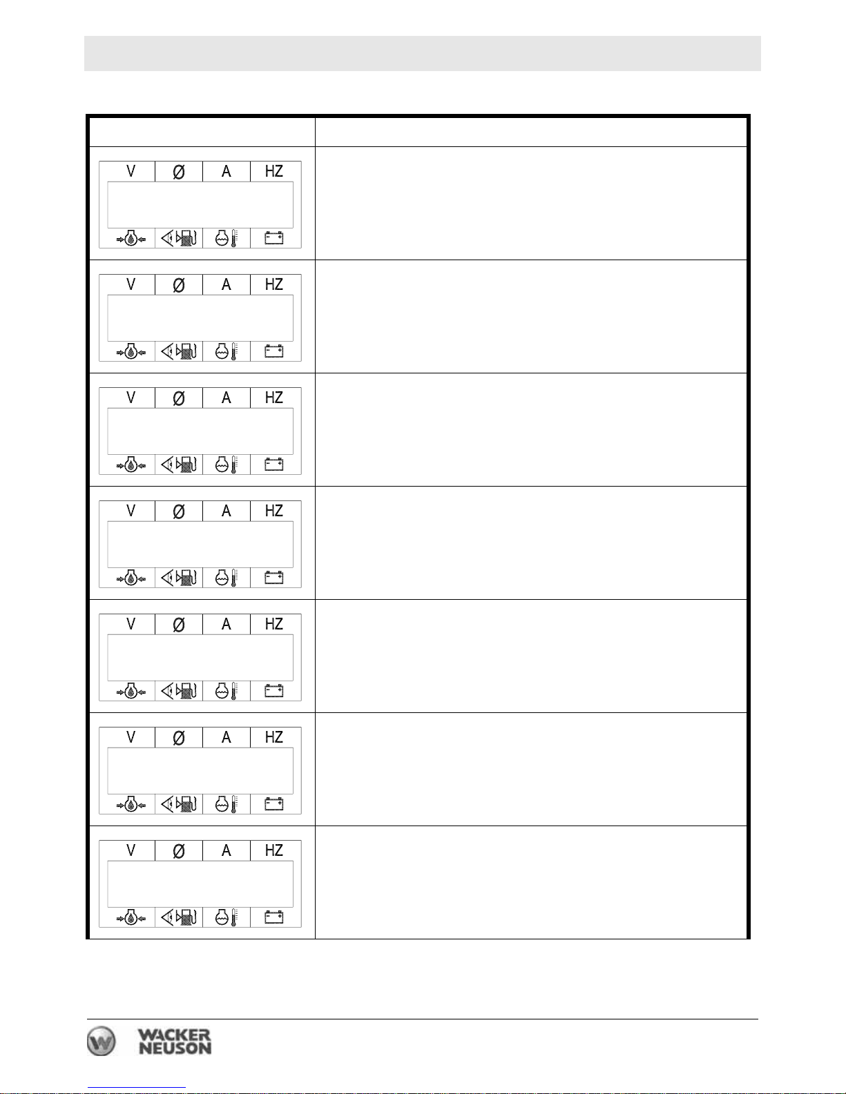
G 85 (9305), G 125, G 160
ECM Display Description
Start of the boot-up sequence. The ECM display reads
“Initializing” and shows the model of the generator. If the
Initializing
G 85
Time to Service
250
Cranking 1 of 3
model displayed does not match the model of the generator, call Wacker Neuson Service.
The ECM displays the countdown time until the next
scheduled service. The timer starts at 250 and counts
down to 0.
The ECM displays this screen during the first cranking
cycle.
80 P2 0 60.0
71 75% 87 12.7
Under Frequency
Enabled
480 P2 0 60.0
71 75% 87 12.7
Engine Protection
Enabled
The ECM displays this screen as soon as the engine
starts. Note that some of the values such as voltage, ma y
not be up to their running values at this stage of the
sequence.
The ECM displays this screen to let the operator know
that the under frequency system (engine speed) has
been enabled.
At this point in the sequence, the ECM displays running
values.
The ECM displays this screen to let the operator know
that the engine protection system has been enabled.
26 wc_tx000713gb.fm
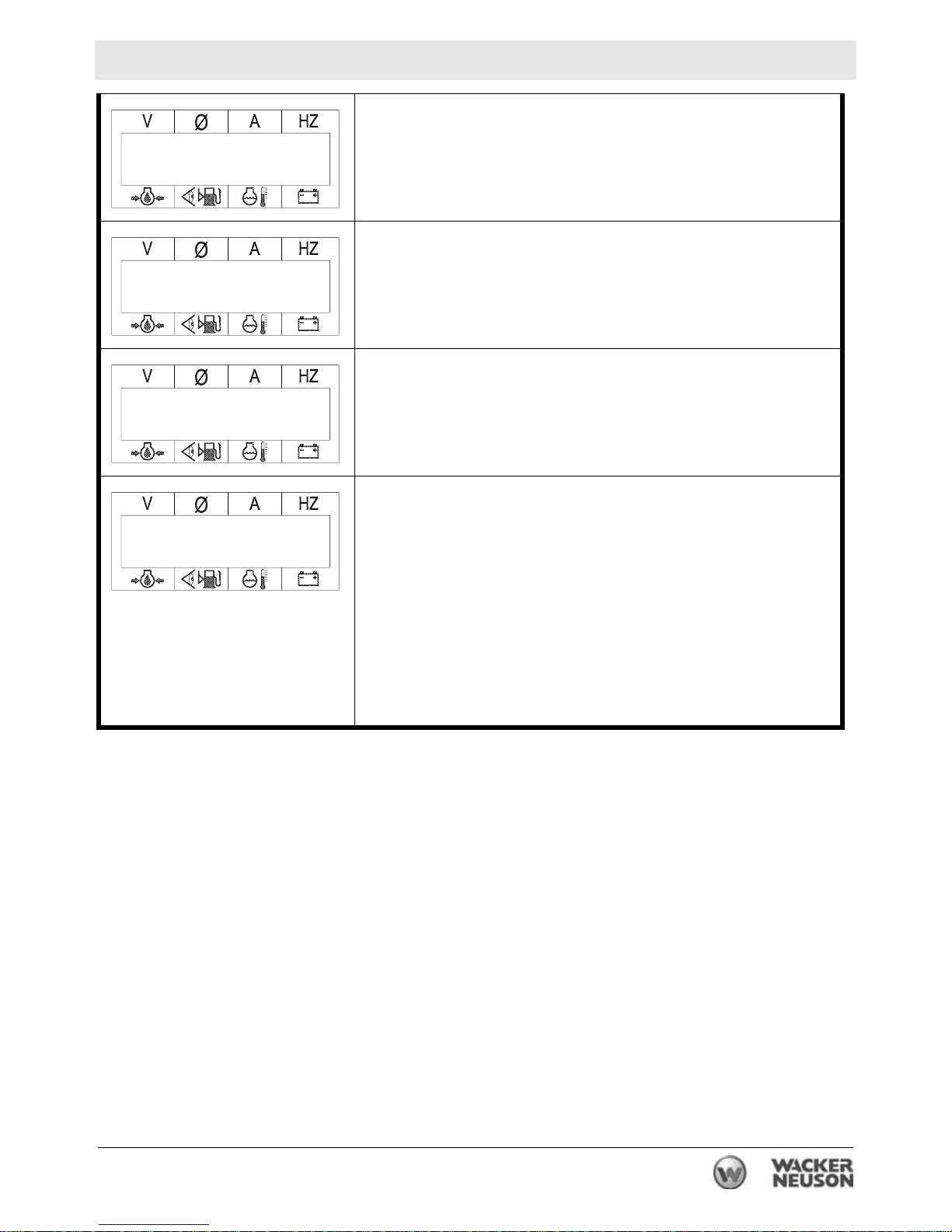
Mobile Generator ECM Background Information
The ECM displays the A C configuration as determined by
AC Configuration
Alt Protection
Enabled
Rated Volts L to L
480 P2 0 60.0
71 75% 87 12.7
the position of the voltage selector switch (VSS).
The ECM displays this screen to let the operator know
that the alternator protection system has been enabled.
The ECM displays the line-to-line voltage . (This screen is
shown for 3-phase VSS positions only.)
At this point, the ECM displays the run screen and the
values for the main generator variables: voltage, phase*
(leg), amperage, hertz (For generators with engines that
include ECUs, the Hz reading will be 60.0. For all others
the reading will be 61.5.) The ECM will also display the
values for the main engine variables: oil pressure, fuel
tank quantity, engine temperature, and battery voltage.
*Note: The ECM displa y scrolls through each phase (P1,
P2, P3) if in the 3-phase mode, or L1, L3, and L1 + L3 if
in the single-phase mode.
wc_tx000713gb.fm 27

ECM Background Information Mobile Generator
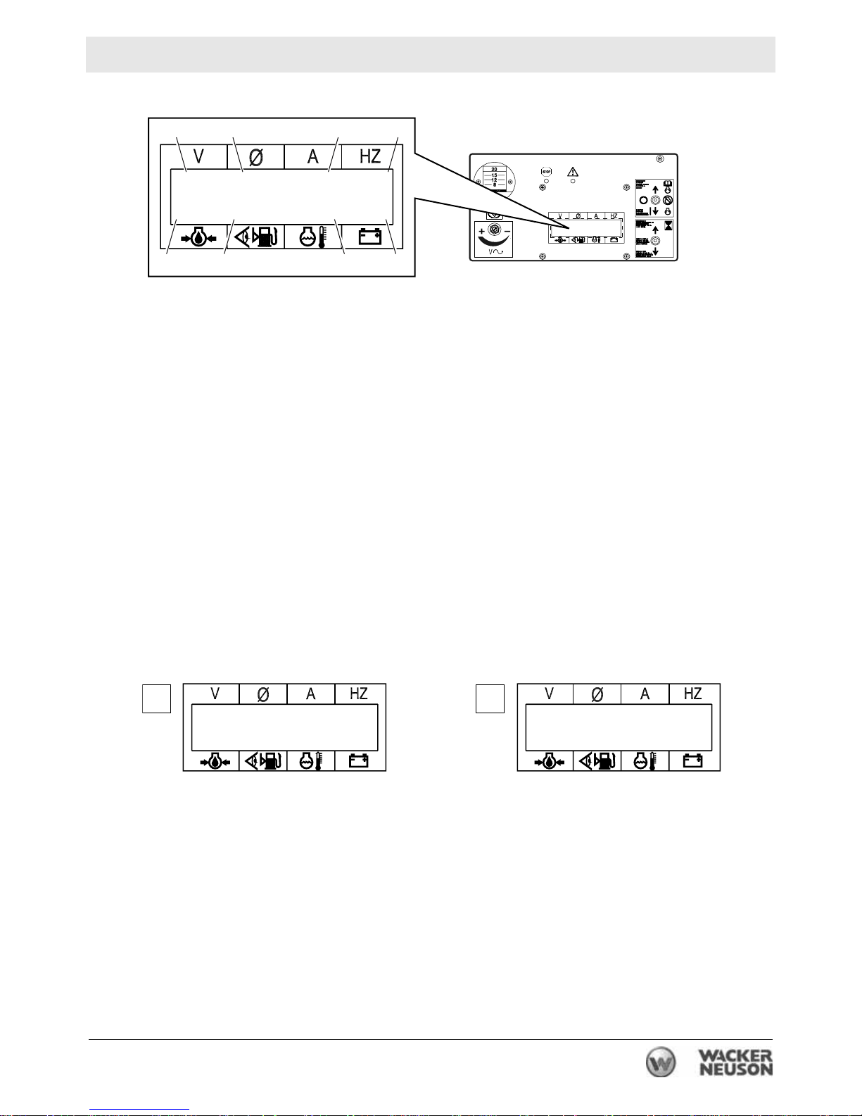
4.3 Display Variables and Values
See Graphic: wc_gr002944
• Generator Variables
The values shown in the top line of the ECM display are all variables
from the generator side of the machine. They are:
(1) voltage (V)
(2) phase (Ø) (or leg for single phase)
(3) amperage (A)
(4) frequency (Hz)
• Engine Variables
The values shown in the lower line of the ECM display are all variables
from the engine side of the machine. They are:
(5) engine oil pressure (psi)
(6) fuel tank quantity (shown in percentage of capacity)
(7) engine temperature (°F)
(8) battery voltage (V)
• Blinking Values
When a value on the ECM display blinks on and off, it signifies that the
variable (temperature, fuel capacity, etc.) is in a pre-alarm state. For
example, the value for the temperature reading will blink when the
temperature of the generator is below 23°C (74°F). This simply
signifies that the manifold heater (or glow plugs) will be energized to
aid in engine starting. The fuel capacity reading will blink when it is
below 25%. This tells the operator that the generator will be requiring
fuel soon. See Section Additional Variables Monitored by the ECM.
Note: If your generator has a block heater, the temperature reading
should not blink. If it does, check the block heater to make sure it is
functioning properly.
• ND (No Data), 0 (zero), or Blank Values
When a value on the ECM display reads ND, 0 (zero), or is blank, it
signifies that there is no data available for the variable.
28 wc_tx000713gb.fm
Mobile Generator ECM Background Information
1
2
3 4
481 P2 0 60.0
71 24% 87 12.7
5
678
wc_gr002944
4.4 ECM Display Screens—Start Switch in Remote Position
See Graphic: wc_gr002943
When the start switch is placed in the REMOTE position, the following
screens are displayed.
4.4.1 “Initializing”
The ECM display reads “Initializing” and shows the model of the
generator. If the model displayed does not match the model of the
generator, call Wacker Neuson Service.
4.4.2 “Unit in Auto”
The ECM displays “Unit in Auto” and the values for oil pressure,
percentage of fuel remaining, engine temperature, and voltage of the
battery.
12
Initializing
G85
Unit in Auto
0 50% 74 12.7
wc_gr002943
wc_tx000713gb.fm 29
ECM Background Information Mobile Generator
4.5 Additional Variables Monitored by the ECM
Holding the toggle switch in the HOURS/RESET position allows the
operator to view additional variables monitored by the ECM. It also
allows the time-to-service countdown timer to be reset. To reset the
countdown timer, hold the toggle switch in the HOURS/RESET
position for approximately 30 seconds or until all the screens have
been scrolled through twice. There are three different sets of additional
variables. Each of the following categories of generators has its own
unique set: standard, those generators with cold weather packages or
custom features, and those with the John Deere engine that includes
the electronic Engine Control Unit (ECU). All three sets of additional
variables are listed below, along with typical no load values. Note: The
values from your generator may differ slightly from those shown here.
G 25, G 50, G 70, G 85 (9310) Standard Models
ECM Display Description
Running Time
0.6
Time to Service
250
FOR SALES AND
SERVICE CONTACT
YOUR LOCAL
WACKER DEALER
The display shows the amount of time, in 1/10 hour segments, that the engine has been running.
The display shows the amount of time left until service on
the machine is required. To reset the timer to 250 hours,
hold the Hours/Reset toggle switch in the up position until
all the screens have been scrolled through twice.
Some ECMs include this message.
Some ECMs include this message.
30 wc_tx000713gb.fm
 Loading...