

Wacker Neuson G 2.5A, GS 5.6A, GS 8.5V, GS 9.7V, G 3.7A Repair Manual
...
www.wackergroup.com
Portable Generators
G 2.5A
G 3.7A
G 5.6A
GS 5.6A
GS 8.5V
GS 9.7V
REPAIR MANUAL
0112013 004
1002 en
0112013


Portable Generator Repair Foreword
wc_tx000224gb.fm i
Operating / Parts Information
You must be familiar with the operation of this machine before you
attempt to troubleshoot or make any repairs to it. Basic operating and
maintenance procedures are described in the operator’s / parts
manual supplied with the machine. The operator’s / parts manual
should be kept with the machine. Use it to order replacement parts
when needed. If this manual becomes lost, please contact Wacker
Corporation to order a replacement.
Damage caused by misuse or neglect of the unit should be brought to
the attention of the operator, to prevent similar occurrences from
happening in the future.
This manual provides information and procedures to safely repair and
maintain this Wacker model. For your own safety and protection from
injury, carefully read, understand and observe the safety instructions
described in this manual. THE INFORMATION CONTAINED IN THIS
MANUAL WAS BASED ON MACHINES IN PRODUCTION A T THE
TIME OF PUBLICATION. WACKER CORPORATION RESERVES
THE RIGHT TO CHANGE ANY PORTION OF THIS INFORMATION
WITHOUT NOTICE.
This manual covers machines with Item Number:
0007188, 0007189, 0007190, 0007191, 0007661, 0007662

Foreword P o rtable Generator Repair
wc_tx000224gb.fm ii

Portable Generat or R e p a ir Table of C ontents
wc_bo0112013004gbTOC.fm 1
1. Foreword 5
2. Safety Information 6
2.1 Laws Pertaining to Spark Arresters ...................................................... 6
2.2 Operating Safety .................................................................................. 7
2.3 Operator Safety while using Internal Combustion Engines .................. 8
2.4 Service Safety ...................................................................................... 9
2.5 Label Locations ..................................................................................10
2.6 Safety and Operating Labels .............................................................. 13
3. Technical Data 18
3.1 Generator ........................................................................................... 18
3.2 Engine ................................................................................................ 22
4. Power Requirements 26
4.1 Determining Power Requirements ..................................................... 26
4.2 Outdoor Installation ............................................................................27
4.3 Indoor Installation .................................. ......... ......... .......... ......... ........27
4.4 Grounding the Generator ................................................................... 28
4.5 Use of Extension Cords ...................................................................... 29
5. G 2.5A 30
5.1 Theory of Operation – Capacitor Generators ..................................... 30
5.2 Rotor ................................................................................................... 31
5.3 Stator .................................................................................................. 31
5.4 Capacitor ............................................................................................ 32
5.5 Diodes ................................................................................................ 32
5.6 Circuit Breaker .................................................................................... 33
5.7 Ground Fault Interruptor ..................................................................... 34
5.8 Capacitors .......................................................................................... 35
5.9 Engine Speed .....................................................................................36
5.10 Loss of Residual Magnetism .............................................................. 37

Table of Contents Portable Generator Repair
wc_bo0112013004gbTOC.fm 2
5.11 Receptacle Panel Wiring .....................................................................38
5.12 Rotor Diode Testing ............................................................................38
5.13 Stator Winding Test .............................................................................39
5.14 Rotor Winding Test ..............................................................................40
5.15 Generator Disassembly .......................................................................41
5.16 Generator Assembly ............................................................................43
5.17 Troubleshooting ...................................................................................44
5.18 Periodic Maintenance Schedule ......................................... ......... ........45
5.19 Engine Service . .................................................................. .................45
5.20 Storing / Transporting ..........................................................................46
5.21 Wiring Schematic ................ ......... .......... ......... ......... .......... ......... ........47
6. G 3.7A;G/GS 5.6A;GS 8.5V;GS 9.7V 48
6.1 Theory of Operation – Brush Generators ............................................48
6.2 Rotor ....................................................................................................49
6.3 Stator ...................................................................................................49
6.4 Automatic Voltage Regulator ...............................................................49
6.5 Choke ..................................................................................................49
6.6 Bridge Rectifier ....................................................................................50
6.7 Engine Auto Idle Module (G 3.7A, G 5.6A and GS 5.6A Models) .......51
6.8 Engine Auto Idle Module (GS 8.5A and GS 9.7A Models) ..................52
6.9 Voltage Selector Switch (G 3.7A, G 5.6A and GS 5.6A Models) ........52
6.10 Checking the Voltage Selector Switch Functional Output
(G 3.7A, G 5.6A and GS 5.6A Models)................................................53
6.11 Main Circuit Breaker ............................................................................54
6.12 Ground Fault Interrupt .........................................................................54
6.13 Choke Test ..........................................................................................56
6.14 Engine Speed (G 3.7A, G 5.6A and GS 5.6A Models) ........................57
6.15 Auto Idle Switch ...................................................................................58
6.16 Checking Engine Electronic Governor Speed
(GS 8.5V and GS 9.7V models) .........................................................59
6.17 Removing and Installing Electronic Governor
(GS 8.5V and GS 9.7V Models) ..........................................................61
6.18 Receptacle Panel Wiring .....................................................................62
6.19 Loss of Residual Magnetism in Rotor ..................................................62
6.20 Diode Bridge ................................. .......... .............................................64
6.21 Stator Windings ...................................................................................65
6.22 Rotor Windings ....................................................................................67
6.23 Automatic Voltage Regulator ...............................................................68

Portable Generat or R e p a ir Table of C ontents
wc_bo0112013004gbTOC.fm 3
6.24 Slip Rings and Brushes ...................................................................... 69
6.25 Generator Disassembly ...................................................................... 70
6.26 Generator Assembly ........................................................................... 73
6.27 Troubleshooting ..................................................................................74
6.28
Period ic Main t enance S chedule (G 3.7A, G 5. 6A, and G S5. 6A Models)
75
6.29 Engine Service (G 3.7A, G 5.6A, and GS 5.6A Models) .................... 75
6.30 Periodic Maintenance Schedule (GS 8.5V and GS 9.7V Models) ...... 76
6.31 Engine Service (GS 8.5V and GS 9.7V Models) ................................ 76
6.32 Generator Wiring Schematic (G 3.7A, G 5.6A, and GS 5.6A Models) 77
6.33 Engine Wiring Schematic (G 3.7A, G 5.6A, and GS 5.6A Models) .... 79
6.34 Generator Wiring Schematic (GS 8.5V and GS 9.7V Models) ........... 80
6.35 Vanguard Engine Wiring Schematic (GS 8.5V and GS 9.7V Models) 83
6.36 Vanguard Key Switch ........................................................ ......... ........84
6.37 Storing ................................................................................................ 85
6.38 Transporting ....................................................................................... 85

Table of Contents Portable Generator Repair
wc_bo0112013004gbTOC.fm 4

Foreword
wc_si000081gb.fm 5
CALIFORNIA
Proposition 65 Warning:
Engine exhaust, some of its constituents, and certain vehicle
components cont ain or em it chemical s known to the State of Califo rnia
to cause cancer and birth defects or other reproductive harm.
1. Foreword
This manual provides information and procedures to safely operate
and maintain this Wacker model. For your own safety and protection
from injury, carefully read, understand and observe the safety
instructions described in this manual.
Keep this manual or a copy of it with the machine. If you lose this
manual or need an additional copy, please contact Wacker
Corporation. This machine is built with user safety in mind; however,
it can present hazards if improperly operated and serviced. Follow
operating instructions carefully! If you have questions about operating
or servicing this equipment, please contact Wacker Corporation.
The information contained in this manual was based on machines in
production at the time of publi cation. W acker Corpora tion reserves the
right to change any portion of this information without notice.
All rights, especially copying and distribution rights, are reserved.
Copyright 2003 by Wacker Corporation.
No part of this publication may be reproduced in any form or by any
means, electronic or mechanical, including photocopying, without
express written permission from Wacker Corporation.
Any type of reproduction or distribution not authorized by Wacker
Corporation represents an infringement of valid copyrights and will be
prosecuted. We expressly reserve the right to make technical
modifications, even without due notice, which aim at improving our
machines or their safety standards.
WARNING
Safety Information Portable Generator Repair
wc_si000081gb.fm 6
2. Safety Information
This manual contains DANGER, WARNING, CAUTION, and NOTE
callouts which must be followed to reduce the possibility of personal
injury, damage to the equipment, or improper service.
This is the safety alert symbol. It is used to alert you to potential
personal injury hazards. Obey all safety messages that follow this
symbol to avoid possible injury or death.
DANGER indicates an imminently hazardous situation which, if not
avoided, will result in death or serious injury.
WARNING indicates a potentially hazardous situation which, if not
avoided, could result in death or serious injury.
CAUTION indicates a potentially hazardous situation which, if not
avoided, may result in minor or moderate injury.
CAUTION: Used without the safety alert symbol, CAUTION indicates
a potentially hazardous situation which, if not avoided, may result in
property damage.
2.1 Laws Pertaining to Spark Arresters
Notice: State Health Safety Codes and Public Resources Codes
specify that in certain locations spark arresters be used on internal
combustion engines that use hydrocarbon fuels. A spark arrester is a
device designed to prevent accidental discharge of sparks or flames
from the engine exhaust. Spark arresters are qualified and rated by
the United States Forest Service for this purpose.
In order to comply with local laws regarding spark arresters, consult
the engine distributor or the local Health and Safety Administrator.
DANGER
WARNING
CAUTION
Portable Generator Repair Safety Information
wc_si000081gb.fm 7
2.2 Operating Safety
BACKFEED FROM THE GENERATOR INTO THE PUBLIC POWER
DISTRIBUTION SYSTEM CAN CAUSE SERIOUS INJURY OR
DEATH TO UTILITY WORKERS!
Improper connection of generator to a building's electrical system can
allow electrical current from the gene rato r to backfeed in to utility lines.
This may result in electrocution of utility workers, fire, or explosion.
Connections to a building's electrical system must be made by a
qualified electrician and comply with all applicable laws and electrical
codes.
If connected to a building's electrical system the generator must meet
the power, voltage, and frequency requirements of the equipment in
the building. Differences in power, voltage, and frequency
requirements may exist and improper connection may lead to
equipment damage, fire, and personal injury or death.
Familiarity and proper training are required for the safe operation of
equipment! Equipm ent ope rated imprope rly or by untra i ned per sonnel
can be dangerous! Read the operating instructions contained in both
this manual and the engine manual and familiarize yourself with the
location and proper use of all controls. Inexperienced ope rators should
receive instruction from someone familiar with the equipment before
being allowed to operate the machine.
2.2.1 NEVER operate generator when open containers of fuel, paint, or
other flammable liquids are near.
2.2.2 NEVER operate g enerator, or t ools atta ched to the g enerator , with wet
hands.
2.2.3 NEVER use worn electrical cords. Severe electrical shock and
equipment damage may result.
2.2.4 NEVER run electrical cords under the generator, or over vibrating or
hot parts.
2.2.5 NEVER enclose or cover generator when in use or when hot.
2.2.6 NEVER overload generator. The total amperage of the tools and
equipment attached to the generator must not exceed the load rating
of the generator.
2.2.7 NEVER operate machine in snow, rain, or standing water.
2.2.8 NEVER allow untraine d personnel to ope rate or servi ce the genera tor.
The generator set should be set up by a trained electrician.
2.2.9 ALWAYS store equipment properly when it is not being used.
Equipment shoul d be stored i n a clean , dry l ocation out o f the rea ch of
children.
2.2.10 ALWAYS be sure machine is on a firm, level surface and will not tip,
roll, slide, or fall while operating.
DANGER
WARNING

Safety Information Portable Generator Repair
wc_si000081gb.fm 8
2.2.11 ALWAYS transport generator in an upright position.
2.2.12 ALWAYS keep machine at least one meter (three feet) away from
structures, buildings and other equipment during use.
2.2.13 ALWAYS keep the ar ea i mmedi a tely sur roun ding the generator cl e an,
neat and free of debris. Make sure that the area overhead is clear of
debris that could fall onto or into the generator, or exhaust
compartment.
2.2.14 ALWAYS remove all tools, cor ds, and othe r loose ite ms from generat or
before starting it.
2.2.15 ALWAYS make certain machine is well-grounded and securely
fastened to a good earthen ground per national and local regulations.
2.3 Op erator Safety while using Internal Combustion Engines
Internal combustion e ngines p resen t special ha zards d uring o pera ti on
and fueling! Read and follow warning instructions in engine owner's
manual and safety guidelines below. Failure to follow warnings and
safety guidelines could result in severe injury or death.
2.3.1 DO NOT run machine indoors or in an enclosed area such as a deep
trench unless adequate ventilation, through such items as exhaust
fans or hoses, is provided. Exhaust gas from the engine contains
poisonous carbon monoxide gas; exposure to carbon monoxide can
cause loss of consciousness and may lead to death.
2.3.2 DO NOT smoke while operating machine.
2.3.3 DO NOT smoke when refueling engine.
2.3.4 DO NOT refuel hot or running engine.
2.3.5 DO NOT refuel engine near open flame.
2.3.6 DO NOT spill fuel when refueling engine.
2.3.7 DO NOT run engine near open flames.
2.3.8 DO NOT start engine if fuel has spilled or an o dor of fuel is present.
Move generator away from the spill and wipe generator dry before
starting.
2.3.9 ALWAYS refill fue l tank in well-ventilated area.
2.3.10 ALWAYS replace fuel tank cap after refueling.
2.3.11 ALWAYS check fuel lines and fuel tank for leaks and cracks before
starting engine. Do not run machine if fuel leaks are present or fuel
lines are loose.
DANGER

Portable Generator Repair Safety Information
wc_si000081gb.fm 9
2.4 Service Safe ty
Poorly maintained equipment can become a safety hazard! In order
for the equipment to operate safely and properly over a long period of
time, periodic maintenance and occasional repairs are necessary. If
the generator is experiencing problems or is being serviced, attach a
"DO NOT ST ART" sign to the con trol panel to no tify other p eople of i ts
condition.
2.4.1 DO NOT use gas oli ne o r o ther types of fuels or flammable solvent s to
clean parts, especially in enclosed areas. Fumes from fuels and
solvents can become explosive.
2.4.2 DO NOT attempt to clean or service machine while it is running.
2.4.3 DO NOT modify the equ ipment with out express written approval of the
manufacturer.
2.4.4 DO NOT allow water to accumulate around the base of the machine.
If water is present, move the machine and allow it to dry before
servicing.
2.4.5 DO NOT service machine if clothing or skin is wet.
2.4.6 DO NOT allow untrained personnel to service this equipment. Only
trained electri cal technicians should be allo wed to service the e lectrical
components of this equipment.
2.4.7 ALWAYS keep machine clean and labels legible. Replace all missing
and hard-to-read labels. Labels provide important operating
instructions and warn of dangers and hazards.
2.4.8 ALWAYS replace safety devices and guards after repairs and
maintenance.
2.4.9 ALWAYS let engine cool before transporting or servicing.
2.4.10 ALWAYS keep hands, feet, and l oose clothing away fro m moving parts
on generator and engine.
2.4.11 ALWAYS turn engine off before servicing generator. If the engine has
electric start, disconnect negative terminal on battery
2.4.12 ALWAYS keep fuel lines in good condition and properly connected.
Leaking fuel and fumes are extremely explosive.
WARNING
Safety Information Portable Generator Repair
wc_si000081gb.fm 10
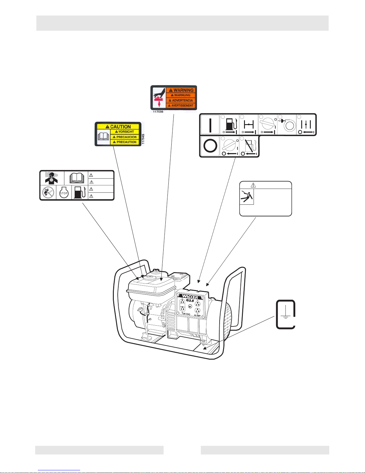
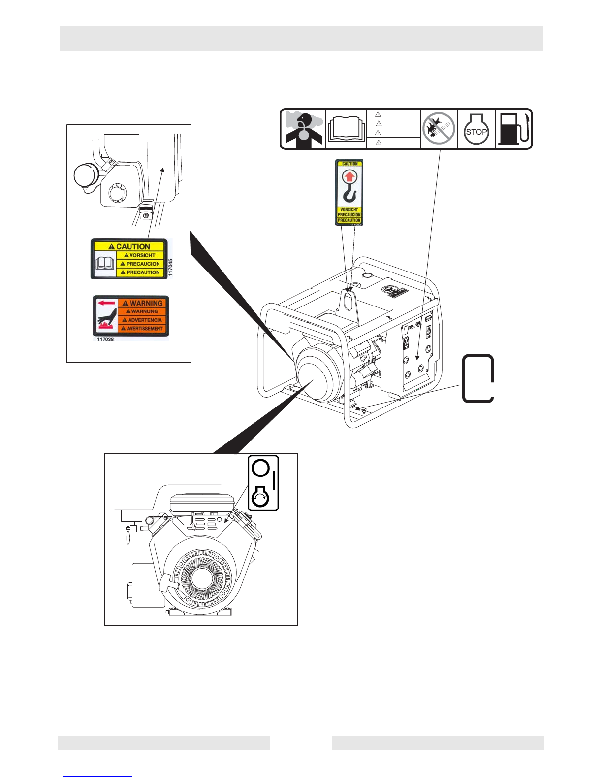
2.5 Label Locations
G 2.5A
w cgr 0 0 0 5 5 2
GND
88897
1
2
3
4
5
1
2
I M P R O P E R C O N N E C T IO N O F G E N E R A T O R
T O A B U I L D IN G ' S E L E C T R IC A L
S Y S T E M C A N A L L O W E L E C T R IC A L
C U R R E N T F R O M T H E G E N E R A T O R T O
B A C K F E E D I N T O U T I L I T Y L I N E S .
T H IS M A Y R E S U L T I N E L E C T R O C U T I O N
O F U T I L I T Y W O R K E R S , F I R E O R
E X P L O S I O N . C O N N E C T I O N S T O A
B U I L D I N G ' S E L E C T R I C A L S Y S T E M M U S T B E M A D E
B Y A Q U A L I F I E D E L E C T R I C I A N A N D C O M P L Y W I T H
A L L A P P L I C A B L E L A W S A N D E L E C T R I C A L C O D E S .
D A N G E R
STOP
DANGER
GEFAHR
PELIGRO
DANGER
Portable Generator Repair Safety Information
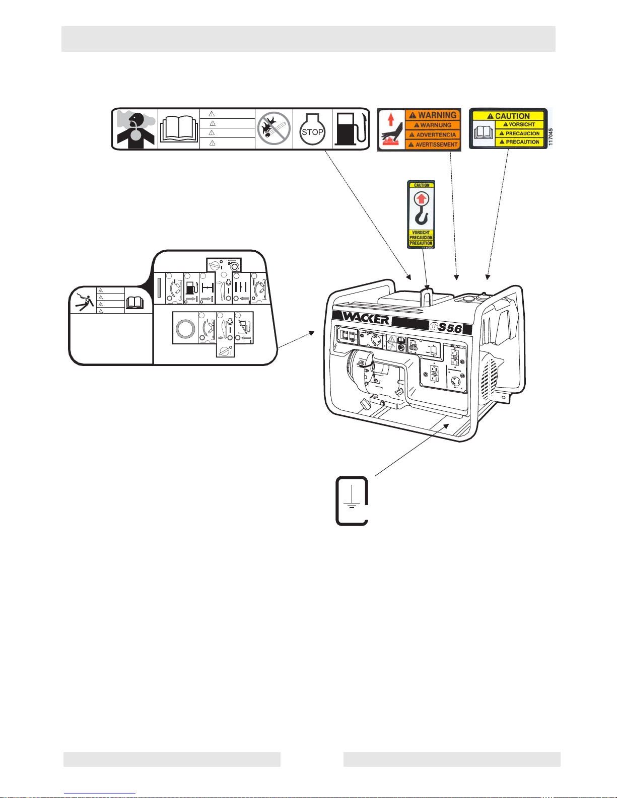
wc_si000081gb.fm 11
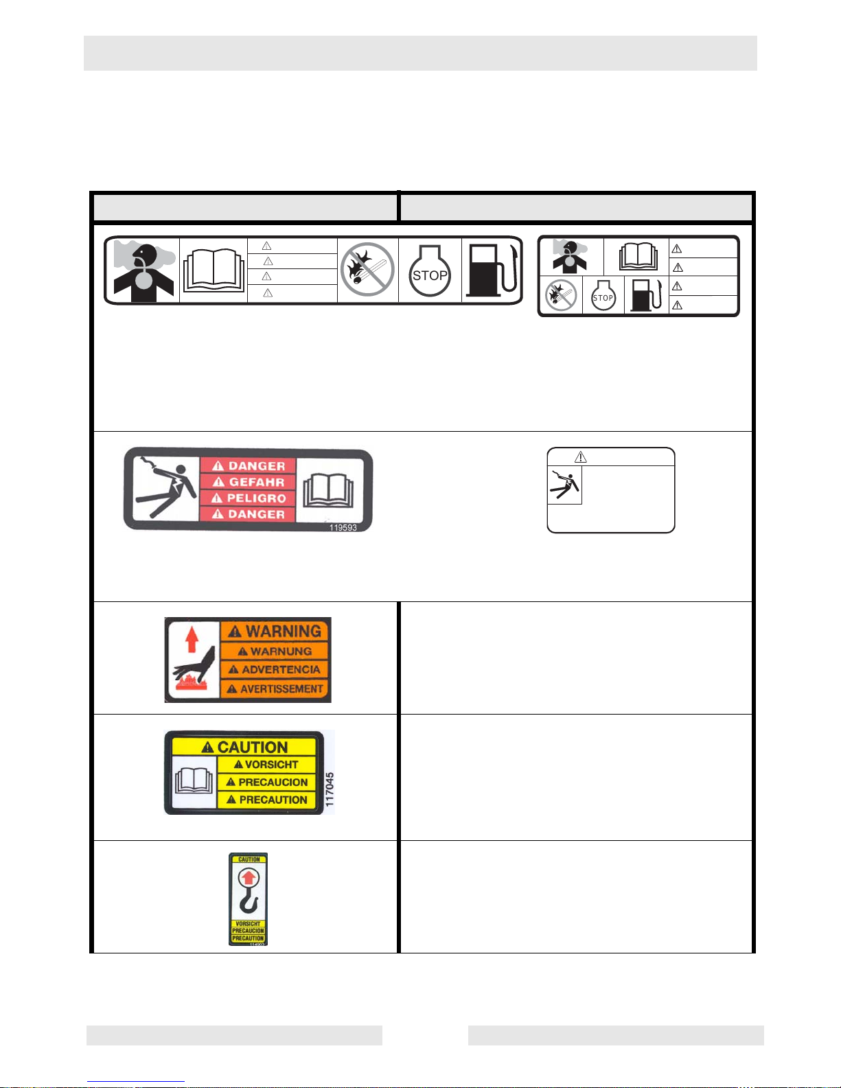
G 3.7A, G 5.6A, and GS 5.6A
w c _ g r 0 0 0 5 4
3
GND
88897
IMPROPER CONNECTION OF GENERATOR TO A
BUILDING'S ELECTRICAL SYSTEM CAN ALLOW
ELECTRICAL CURRENT FROM THE GENERATOR
TO BACKFEED INTO UTILITY LINES. THIS
MAY RESULT IN ELECTROCUTION OF UTILITY
WORKERS, FIRE OR EXPLOSION. CONNECTIONS
TO A BUILDING'S ELECTRICAL SYSTEM MUST
BE MADE BY A QUALIFIED ELECTRICIAN AND
COMPLY WITH ALL APPLICABLE LAWS AND
ELECTRICAL CODES.
4
321
321
656
5
DANGER
GEFAHR
DANGER
PELIGRO
D A N G E R
G E F A H R
D A N G E R
P E L I G R O
S T O P
Safety Information Portable Generator Repair
wc_si000081gb.fm 12
GS 8.5V and GS 9.7V
w c _ g r 0 0 0 5 5 8
GND
88897
D A N G E R
G E F A H R
D A N G E R
P E L I G R O
S T O P
Portable Generator Repair Safety Information
wc_si000081gb.fm 13
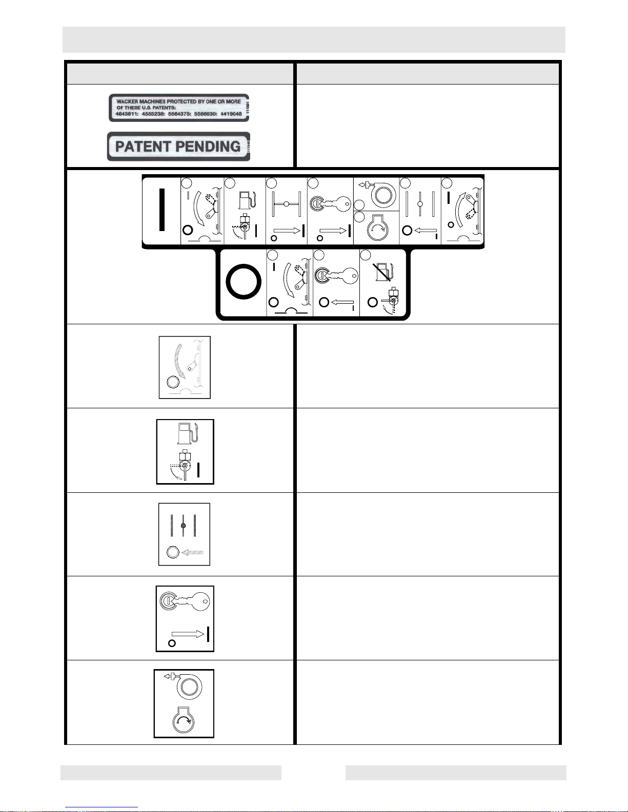
2.6 Safety and Operating Labels
Wacker machines use international pictorial labels where needed.
These labels are described below:
Label Meaning
DANGER!
Engines emit carbon monoxide; operate only in well ventilated area. Read the operator's
manual.
No sparks, flames or burning objects near machine. Shut off engine before refueling.
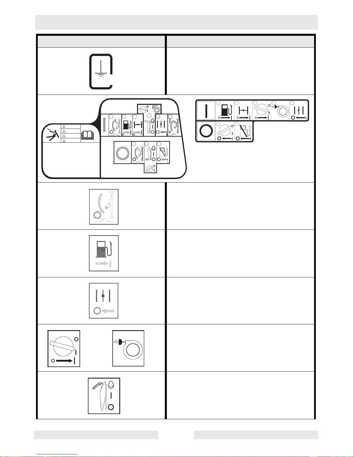
DANGER!
Electric shock hazard. Read operator’s manual for instructions.
WARNING!
Hot surface.
CAUTION!
Read and understand the supplied operator's
manual before operating this machine. Failure
to do so increases the risk of injury to yourself
or others.
CAUTION!
Lifting point
D A N G E R
G E F A H R
D A N G E R
P E L I G R O
S T O P
STOP
DANGER
GEFAHR
PELIGRO
DANGER
I M P R O P E R C O N N E C T I O N O F G E N E R A T O R
T O A B U I L D I N G ' S E L E C T R I C A L
S Y S T E M C A N A L L O W E L E C T R I C A L
C U R R E N T F R O M T H E G E N E R A T O R T O
B A C K F E E D I N T O U T I L I T Y L I N E S .
T H I S M A Y R E S U L T I N E L E C T R O C U T I O N
O F U T I L I T Y W O R K E R S , F I R E O R
E X P L O S I O N . C O N N E C T I O N S T O A
B U I L D I N G ' S E L E C T R I C A L S Y S T E M M U S T B E M A D E
B Y A Q U A L I F I E D E L E C T R I C I A N A N D C O M P L Y W I T H
A L L A P P L I C A B L E L A W S A N D E L E C T R I C A L C O D E S .
D A N G E R
Safety Information Portable Generator Repair
wc_si000081gb.fm 14
Electrical ground.
Open main circuit breaker.
Open fuel flow valve.
Open choke.
Push or turn engine switch to ON position.
Pull rewind starter.
Press engine crank switch to "CRANK" position.
Label Meaning
GND
88897
IMPROPER CONNECTION OF GENERATOR TO A
BUILDING'S ELECTRICAL SYSTEM CAN ALLOW
ELECTRICAL CURRENT FROM THE GENERATOR
TO BACKFEED INTO UTILITY LINES. THIS
MAY RESULT IN ELECTROCUTION OF UTILITY
WORKERS, FIRE OR EXPLOSION. CONNECTIONS
TO A BUILDING'S ELECTRICAL SYSTEM MUST
BE MADE BY A QUALIFIED ELECTRICIAN AND
COMPLY WITH ALL APPLICABLE LAWS AND
ELECTRICAL CODES.
4
321
321
656
5
DANGER
GEFAHR
DANGER
PELIGRO
1
2
3
4
5
1
2
Portable Generator Repair Safety Information
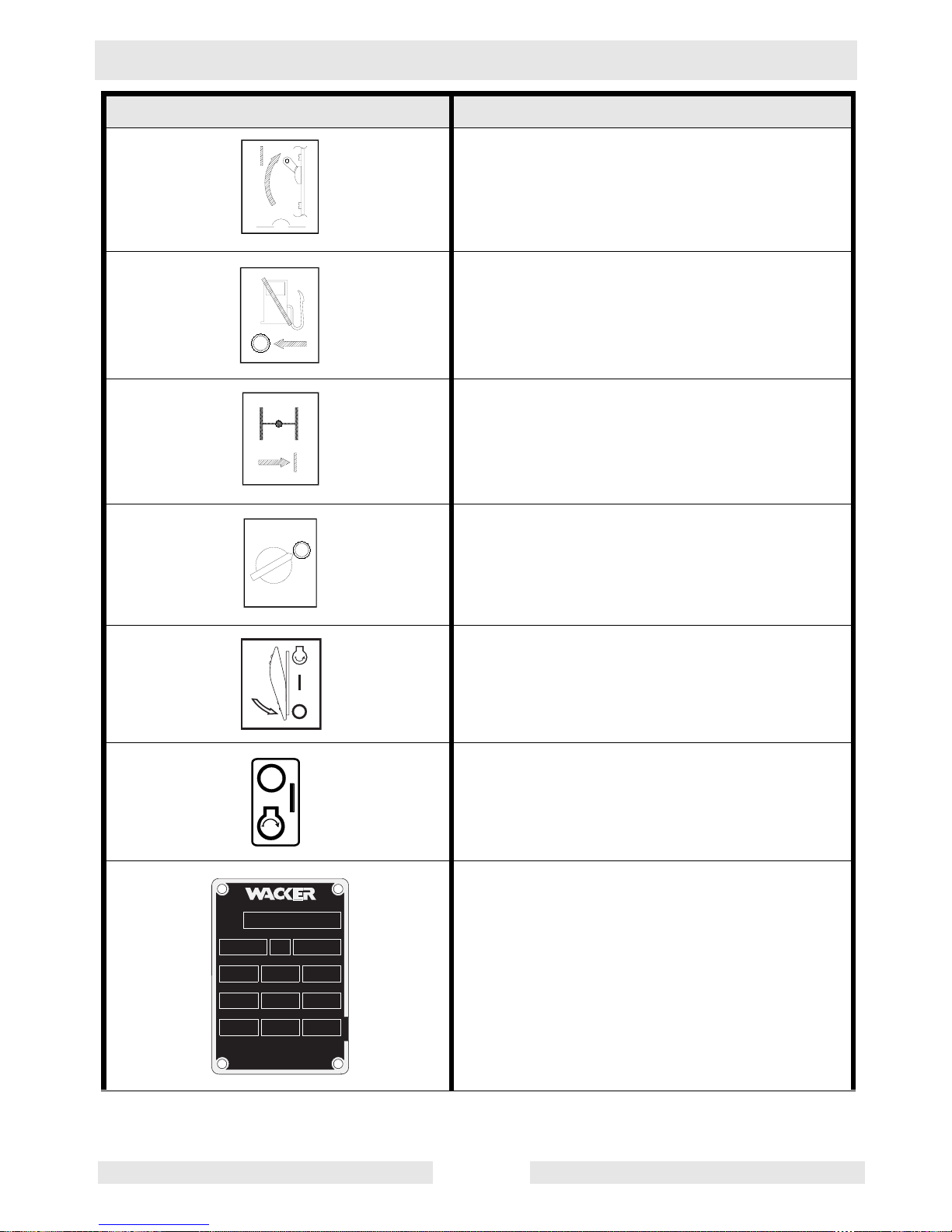
wc_si000081gb.fm 15
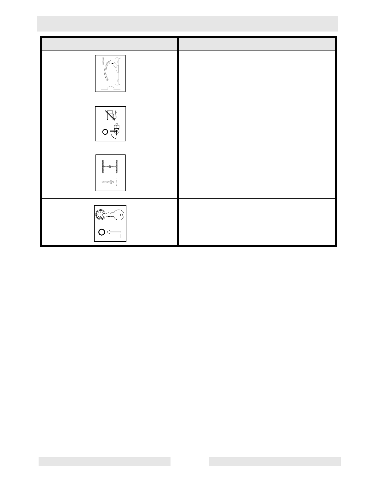
Close main circuit breaker.
Close fuel flow valve.
Close choke.
Push or turn engine switch to OFF position.
Press engine crank switch to "OFF" position.
Key switch:
off
on
start
A nameplate listing the Model Number, Item
Number, Revision, and Serial Number is
attached to each unit. Please record the information found on this plate so it will be available should the nameplate become lost or
damaged. When ordering parts or requesting
service information, you will always be asked
to specify the model, item number, revision
number, and serial number of the unit.
Label Meaning
M E N O M O N E E F A L L S , W I U S A 5 3 0 5 1
M o d e l
S e r i a l N o .
k W m a x
V
I t e m N o .
k g
A
l b s
R e v .
P . F .
h z
M A D E I N U S A
1 1 0 9 9 2
Safety Information Portable Generator Repair
wc_si000081gb.fm 16
This machine may be covered by one or more
patents.
Open main circuit breaker.
Open fuel flow valve.
Open choke.
Turn engine key switch to “ON” position.
Pull rewind starter or turn engine k e y s wi tch to
crank starter.
Label Meaning
1 2
3
4
5B
5A
6
7
1
2
3
Portable Generator Repair Safety Information
wc_si000081gb.fm 17
Close main circuit breaker.
Close fuel flow valve.
Close choke.
Turn engine key switch to “OFF” position.
Label Meaning
Technical Data Portable Generator Repair
wc_td000082gb.fm 18
3. Technical Data
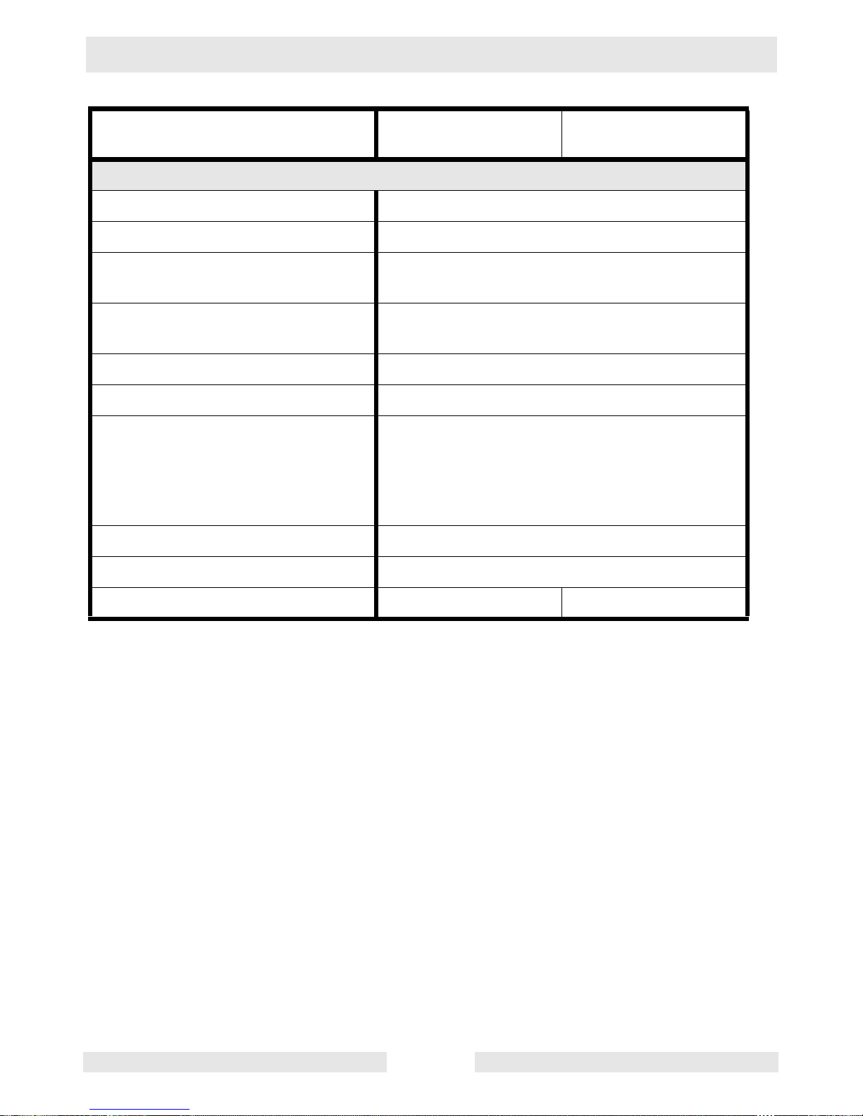
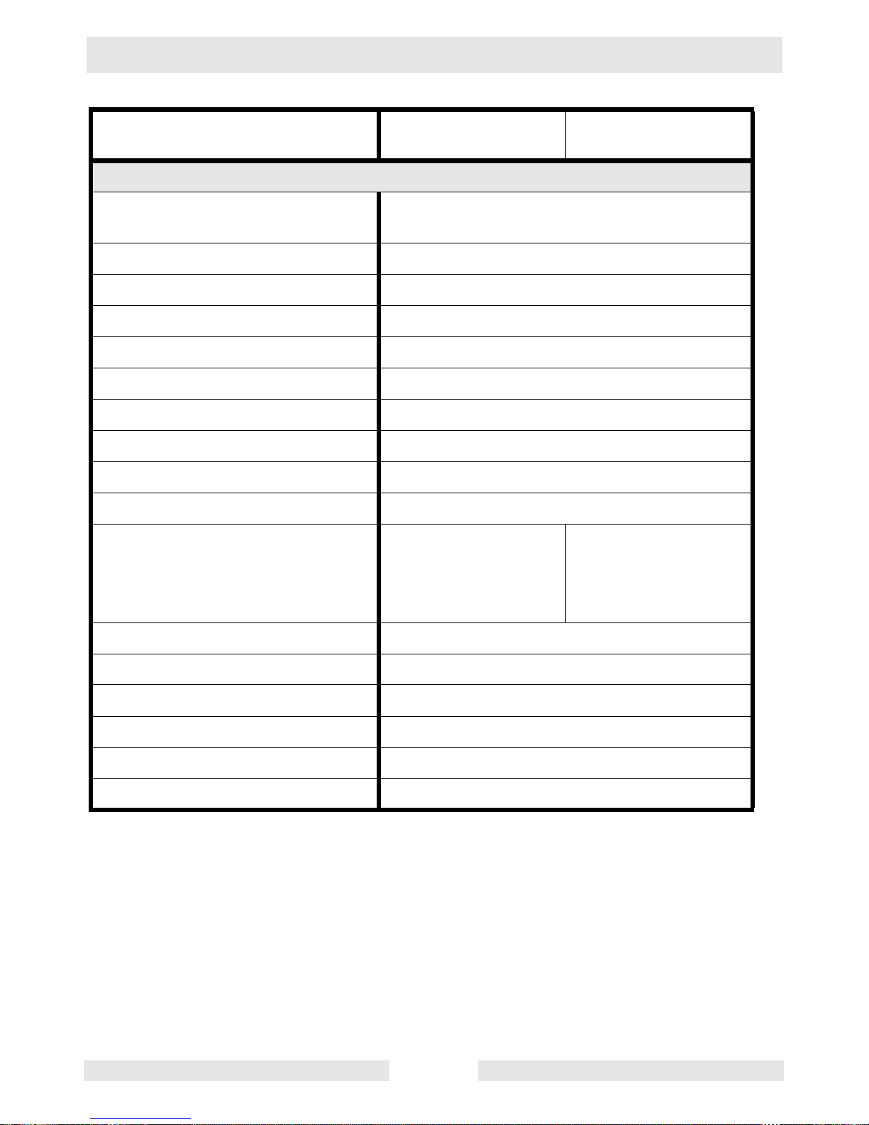
3.1 Generator
Item No. G 2.5A
0007188
Generator
Maximum Output
W
2500
Continuous Output
W
2250
Type Single voltage, single phase, brushless system
AC Voltages Available
volts
phase
120
1ø
Frequency
Hz
60
Power Factor 1.0
AC receptacles:
120V GFI duplex
120V duplex (also protected by GFI)
amp
amp
20
20
Main Circuit Breaker
amp
20
L x W x H
mm (in.)
685 x 445 x 435 (27 x 17.5 x 17)
Weight (dry)
Kg (lbs.)
43 (94)
Portable Generator Repair Technical Data
wc_td000082gb.fm 19
Item No. G 3.7A
0007189
Generator
Maximum Output
W
3700
Continuous Output
W
3320
Type Dual voltage, single phase,
Auto voltage regulator system
AC Voltages Available
volts
phase
120 / 240
1ø
Frequency
Hz
60
Power Factor 1.0
AC receptacles:
120V GFI duplex
120V GFI duplex
120V twist lock
240V twist lock
amp
amp
amp
amp
20
20
30
20
Main Circuit Breaker
amp
32 (2-pole, 16 amp each pole)
L x W x H
mm (in.)
685 x 585 x 530 (27 x 23 x 21)
Weight (dry)
Kg (lbs.)
68 (150)
Technical Data Portable Generator Repair
wc_td000082gb.fm 20
Item No. G 5.6A
0007190
GS 5.6A
0007191
Generator
Maximum Output
W
5600
Continuous Output
W
5350
Type Dual voltage, single phase,
Auto voltage regulator system
AC Voltages Available
volts
phase
120 / 240
1ø
Frequency
Hz
60
Power Factor 1.0
AC receptacles:
120V GFI duplex
120V GFI duplex
120V twist lock
240V twist lock
amp
amp
amp
amp
20
20
30
20
Main Circuit Breaker
amp
48 (2-pole, 24 amp each pole)
L x W x H
mm (in.)
685 x 585 x 530 (27 x 23 x 21)
Weight (dry)
Kg (lbs.)
76 (168) 79 (175)
Portable Generator Repair Technical Data
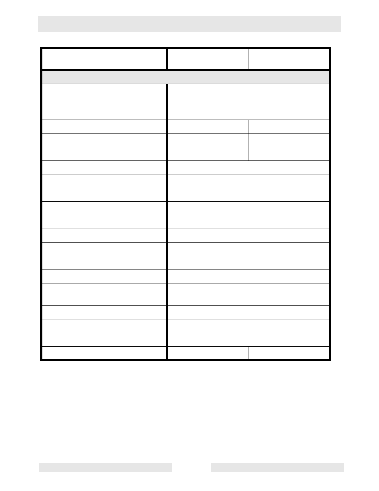
wc_td000082gb.fm 21
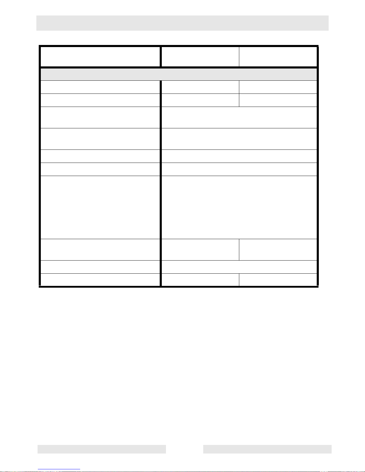
Item No. GS 8.5V
0007661
GS 9.7V
0007662
Generator
Maximum Output
kW / kVA
8.5 / 8.5 9.7 / 9.7
Continuous Output
W
8.2 9.3
Type Dual voltage, single phase,
brush-type system
AC Voltages Available
volts
phase
120 / 240
1ø
Frequency
Hz
60
Power Factor 1.0
AC receptacles:
120V GFI duplex
120V GFI duplex
120V twist lock
120V twist lock
240V twist lock
120/240V twist lock
amp
amp
amp
amp
amp
amp
20
20
20
30
20
30
Continuous Current
at 120V
amp
68.3 77.5
L x W x H
mm (in.)
800 x 635 x 603 (31.5 x 25 x 23.75)
Weight (dry)
Kg (lbs.)
97 (214) 99 (218)
Technical Data Portable Generator Repair
wc_td000082gb.fm 22
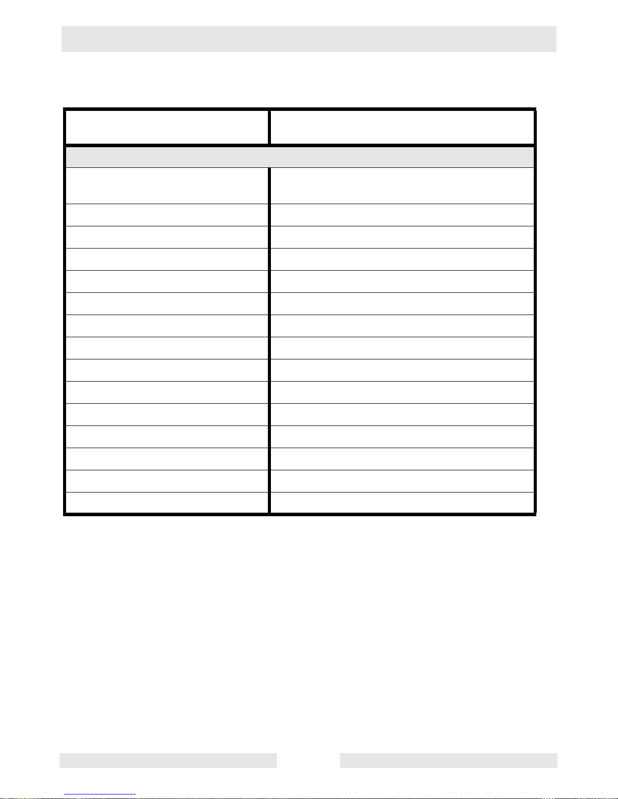
3.2 Engine
Item No. G 2.5A
0007188
Engine
Engine Type Single cylinder, 4-cycle,
air-cooled, gasoline engine
Engine Make Honda
Engine Model GX 160 K1VX
Rated Power
kW (Hp)
4.1 (5.5)
Spark Plug BPR6ES / W20EPR-U
Electrode Gap
mm (in.)
0.7 - 0.8 (0.028 - 0.031)
Engine Speed - full load
rpm
3600 ± 100
Engine Speed - no load
rpm
3700 ± 100
Air Cleaner
type
Dry type with oil-wetted foam pre-cleaner
Engine Lubrication
oil grade
SAE 10W30 service class SF, SE, SD or SC
Engine Oil Capacity
l (oz.)
0.6 (21)
Fuel
type
Regular unleaded gasoline
Fuel Tank Capacity
l (qt.)
3.7 (3.9)
Fuel Consumption
l (qts.)/h r.
1.7 (1.8)
Running Time
hrs.
2.1
Portable Generator Repair Technical Data
wc_td000082gb.fm 23
Item No. G 3.7A
0007189
Engine
Engine Type Single cylinder, 4-cycle,
air-cooled, gasoline engine
Engine Make Honda
Engine Model GX 240 K1
Rated Power
kW (Hp)
5.9 (8)
Spark Plug BPR6ES / W20EPR-U
Electrode Gap
mm (in.)
0.7 - 0.8 (0.028 - 0.031)
Engine Speed - full load
rpm
3600 ± 100
Engine Speed - no load
rpm
3700 ± 100
Auto Idle Speed
rpm
2200 ± 50
Air Cleaner
type
Dry type with oil-wetted foam pre-cleaner
Engine Lubrication
oil grade
SAE 10W30 service class SF, SE, SD or SC
Engine Oil Capacity
l (qts.)
1.1 (1.2)
Fuel
type
Regular unleaded gasoline
Fuel Tank Capacity
l (gal.)
19.5 (5.2)
Fuel Consumption
l (qts.)/h r.
2.6 (2.8)
Running Time
hrs.
7.4
Technical Data Portable Generator Repair
wc_td000082gb.fm 24
Item No. G 5.6A
0007190
GS 5.6A
0007191
Engine
Engine Type Single cylinder, 4-cycle,
air-cooled, gasoline engine
Engine Make Honda
Engine Model GX 340 K1
Rated Power
kW (Hp)
8.2 (11)
Spark Plug BPR6ES / W20EPR-U
Electrode Gap
mm (in.)
0.7 - 0.8 (0.028 - 0.031)
Engine Speed - full load
rpm
3600 ± 100
Engine Speed - no load
rpm
3700 ± 100
Auto Idle Speed
rpm
2200 ± 50
Air Cleaner
type
Dry type with oil-wetted foam pre-cleaner
Battery
type
V/capacity
Size (in.)
N/A Y50-N18L-A or
C50-N18L-A
12V - 20 Amp-hour
8-1/8 x 3-9/16 x 6-7/
16
Engine Lubrication
oil grade
SAE 10W30 service class SF, SE, SD or SC
Engine Oil Capacity
l (qts.)
1.1 (1.2)
Fuel
type
Regular unleaded gasoline
Fuel Tank Capacity
l (gal.)
19.5 (5.2)
Fuel Consumption
l (qts.)/h r.
3.6 (3.8)
Running Time
hrs.
5.4
Portable Generator Repair Technical Data
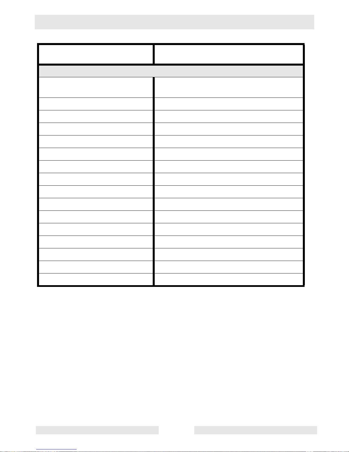
wc_td000082gb.fm 25
Item No. GS 8.5V
0007661
GS 9.7V
0007662
Engine
Engine Type 2 cylinder, 4-cycle,
air-cooled, gasoline engine
Engine Make Briggs and Stratton
Engine Model Vanguard 303447 Vanguard 350447
Rated Power
kW (Hp)
11.9 (16) 13.4 (18)
Displacement
cm3 (in3)
480 (29.3) 570 (34.75)
Spark Plug Champion RC12YC
Electrode Gap
mm (in.)
0.76 (0.030)
Starter
type / V
Electric / 12
Alternator
amp
16
Engine Speed - full load
rpm
3600
Auto Idle Speed
rpm
2200
Valve Clearance (cold)
mm (in.)
0.10–0.16 (0.004–0.006)
Air Cleaner
type
Dual element
Battery
V/size/CCA
12 / 22NF / 230
Engine Lubrication
oil grade
ser vice class
SAE 10W30
SG, SF, or SE
Engine Oil Capacity
l (qts.)
1.6 (1.7)
Fuel
type
Regular unleaded gasoline
Fuel Tank Capacity
l (gal.)
28 (7.4)
Fuel Consumption
l (gal.)/hr.
5.03 (1.33) 6.21 (1.64)
 Loading...