

Page 1

www.wackergroup.com
0152792en 002
0902
Generator
G 2.5A
OPERATOR'S MANUAL
0152792EN
Page 2

DANGER
CARBON MONOXIDE
Using a generator indoors CAN KILL YOU IN MINUTES.
Generator exhaust contains carbon monoxide (CO). This is a poison you cannot see or
smell. If you can smell the generator exhaust, you are breathing CO. But even if you cannot
smell the exhaust, you could be breathing CO.
• NEVER use a generator inside homes, garages, crawlspaces, or other partly enclosed
areas. Deadly levels of carbon monoxide can build up in these areas. Using a fan or
opening windows and doors does NOT supply enough fresh air.
• ONLY use a generator outside and far away from windows, doors, and vents. These
openings can pull in generator exhaust.
Even when you use a generator correctly, CO may leak into the home. ALWAYS use a
battery-powered or battery-backup CO alarm in the home.
If you start to feel sick, dizzy, or weak after the generator has been running, move to fresh
air RIGHT AWAY. See a doctor. You could have carbon monoxide poison.
Page 3

Foreword
wc_tx000001gb.fm
Engine exhaust, some of its constituents, and certain vehicle
components contain o r emit chemicals known to the State of Califor nia
to cause cancer and birth defects or other reproductive harm.
1. Foreword
This manual provides information and procedures to safely operate
and maintain this Wacker m odel. For you r own safet y and prote ction
from injury, carefully read, understand and observe the safety
instructions described in this manual.
Keep this manual or a copy of it with the machine. If you lose this
manual or need an additional copy, please contact Wacker
Corporation. This machine is built with user safety in mind; however,
it can present hazards if improperly operated and serviced. Follow
operating instructions carefully! If you have questions about operating
or servicing this equipment, please contact Wacker Corporation.
The information contained in this manual was based on machines in
production at the time of publication. Wacker Corporation reserves the
right to change any portion of this information without notice.
All rights, especially copying and distribution rights are reserved.
Copyright 2002 by Wacker Corporation.
No part of this publication may be reproduced in any form or by any
means, electronic or mechanical, including photocopying, without
express written permission fr om Wacker Co rp or at io n.
Any type of reproduction or distribution not authorized by Wacker
Corporation represents an infringement of valid copyrights and will be
prosecuted. We expressly reserve the right to make technical
modifications, even without due notice, which aim at improving our
machines or their safety standards.
WARNING
Page 4
G2.5A
Nameplate / Plaque signalétique
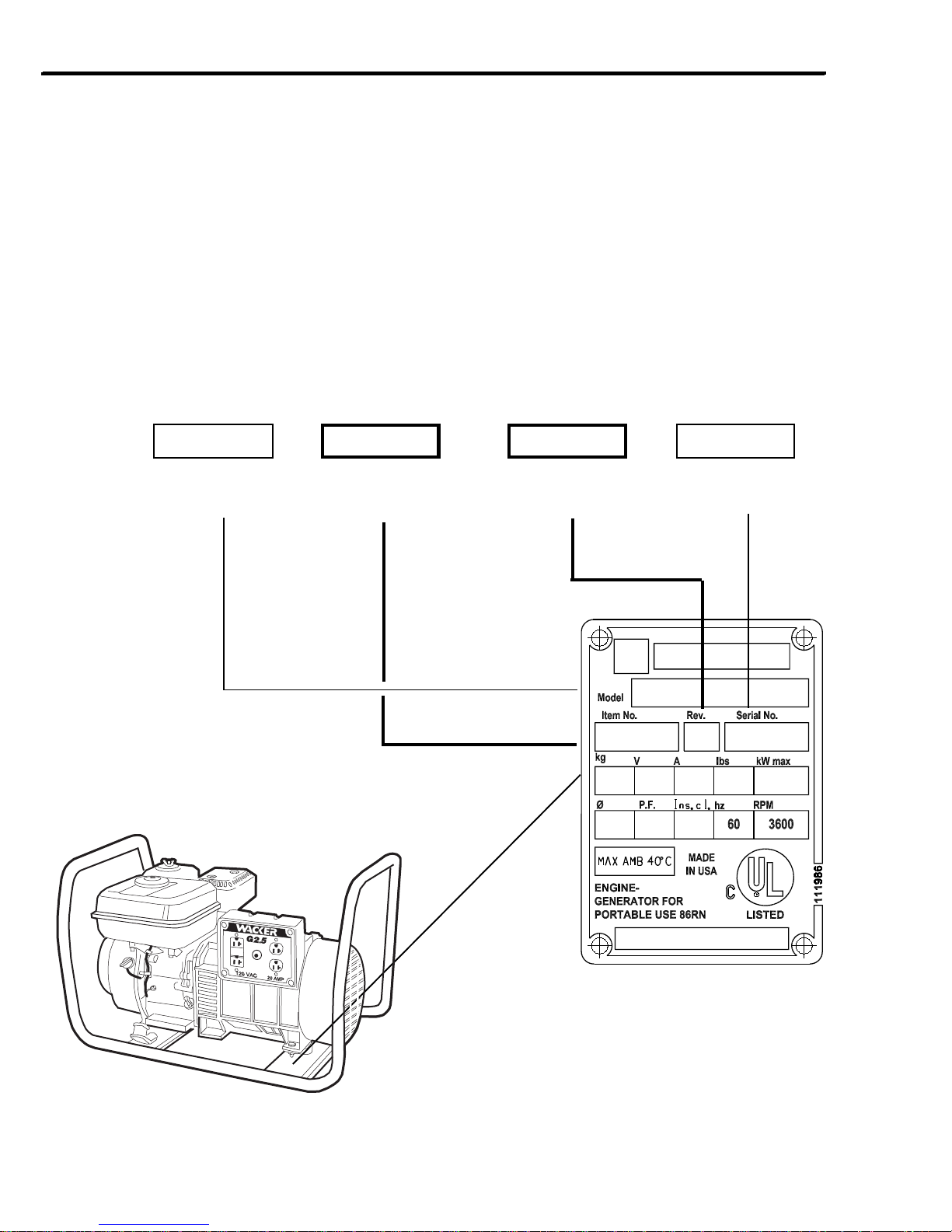
A nameplate listing the Model Number, Item Number, Revision, and Serial Number is attached to each unit. Please
record the information found on this plate so it will be available should the nameplate become lost or damaged. When
ordering parts or requesting service information, you will always be asked to specify the model, item number,
revision number, and serial number of the unit.
Une plaque signalétique mentionnant le modèle, le numéro de référence, le niveau de revision et le numéro de série
est fixée sur chaque machine. Veuillez noter les informations relevées sur cette plaque de façon à ce qu’elles soient
toujours disponibles si la plaque signalétique venait à être perdue ou endommagée. Lorsque vous commandez des
pièces détachées ou vous sollicitez des informations auprès-vente, on vous demandera toujours de préciser
le modèle, le numéro de référence, le niveau de revision et le numéro de série de la machine.
My machine’s numbers are / Les numéros de ma machine sont :
Model number
Modèle
Item Number
Numéro de référence
Revision
Niveau de revision
G2.5A
0009256 101 5010101
Serial Number
Numéro de Série
1038SD43
ii
Page 5

G2.5A
Operating Information
Table of Contents
1.1 Safety Information ..............................................................................1A-2
1.2 Operating Safety ................................................................................1A-3
1.3 Operator Safety while using Internal Combustion Engines.................1A-4
1.4 Service Safety....................................................................................1A-4
1.5 Technical Data ...................................................................................1A-5
1.6 Safety and Operating Labels ..............................................................1A-6
1.7 Label Locations ..................................................................................1A-7
1.8 Application and Power Requirements.................................................1A-8
1.9 Grounding the Generator ...................................................................1A-8
1.10 Outdoor Operation..............................................................................1A-8
1.11 Indoor Operation ................................................................................1A-9
1.12 Use of Extension Cords......................................................................1A-9
1.13 Ground Fault Circuit Interrupt (GFI)..................................................1A-10
1.14 Circuit Breaker Protection ................................................................1A-10
1.15 Before Starting .................................................................................1A-10
1.16 To Start ............................................................................................1A-11
1.17 To Stop ............................................................................................1A-11
1.18 Operating Heavy Loads....................................................................1A-11
1.19 Engine Maintenance.........................................................................1A-12
1.20 New Machines..................................................................................1A-12
1.21 Periodic Maintenance Schedule .......................................................1A-12
1.22 Changing Oil ....................................................................................1A-12
1.23 Servicing Air Cleaner........................................................................1A-13
1.24 Cleaning Sediment Cup....................................................................1A-13
1.25 Carburetor Adjustment .....................................................................1A-14
1.26 Setting Engine Speed.......................................................................1A-14
1.27 Transporting .....................................................................................1A-14
1.28 Storage ............................................................................................1A-15
1.29 Troubleshooting ...............................................................................1A-15
1.30 Wiring Schematic .............................................................................1A-16
1A
1A-1
Page 6
1A OPERATION G2.5A
!
1.1 Safety Information
This manual contains DANGER, WARNING, CAUTION, and NOTE callouts which must be followed to reduce the
possibility of personal injury, damage to the equipment, or improper service.
This is the safety alert symbol. It is used to alert you to potential
personal injury hazards. Obey all safety messages that follow
!
this symbol to avoid possible injury or death.
DANGER
DANGER indicates an imminently hazardous
situation which, if not avoided, will result in
death or serious injury.
!
WARNING
WARNING indicates a potentially hazardous
situation which, if not avoided, could result in
death or serious injury.
!
CAUTION
CAUTION indicates a potentially hazardous
situation which, if not avoided, may result in
minor or moderate injury.
CAUTION: Used without the safety alert symbol,
CAUTION indicates a potentially hazardous situation
which, if not avoided, may result in property damage.
Note:
Contains additional information
important to a procedure.
Laws Pertaining to Spark Arresters
Notice: Some local authorities require that in certain locations, spark arresters be used on internal combustion engines.
A spark arrester is a device designed to prevent the discharge of sparks or flames from the engine exhaust. It is often
required when operating equipment on forested land to reduce the risk of fires. Consult the engine distributor or local
authorities and make sure you comply with regulations regarding spark arresters.
1A-2
Page 7
G2.5A OPERATION 1A
1.2 Operating Safety
Familiarity and proper training are required for the safe operation of electrical equipment! Equipment operated
improperly or by untrained personnel can be dangerous! Read the operating instructions and familiarize yourself with
the location and proper use of all instruments and controls. Inexperienced operators should receive instruction from
someone familiar with the equipment before being allowed to operate the generator.
!
WARNING
NEVER operate generator when open containers of
fuel, paint, or other flammable liquids are near.
NEVER operate generator, or tools attached to the
generator, with wet hands.
NEVER use worn electrical cords. Severe electrical
shock and equipment damage may result.
NEVER run generator indoors or in an enclosed area
unless adequate ventilation, through such items as
exhaust fans or hoses, is provided. Exhaust gas from
the engine contains poisonous carbon monoxide gas;
exposure to carbon monoxide can cause loss of
consciousness and may lead to death.
NEVER run electrical cords under the generator, or
over vibrating or hot parts.
NEVER enclose or cover generator when in use or
when hot.
NEVER overload generator. The total amperage of
the tools and equipment attached to the generator
must not exceed the load rating of the generator.
NEVER allow untrained personnel to operate or service the generator. Know how to operate and stop
generator before starting it.
NEVER operate generator in snow, rain, or standing
water.
ALWAYS keep generator at least one meter away
from structures, buildings, and other equipment during use.
ALWAYS keep generator out of reach of children and
pets.
ALWAYS keep the area immediately surrounding the
generator clean, neat and free of debris.
ALWAYS position and operate generator on a firm,
level surface.
ALWAYS remove all tools, cords, and other loose
items from generator before starting it.
ALWAYS make certain generator is well-grounded
and securely fastened to a good earthen ground.
NEVER stand on the machine.
BACKFEED FROM THE GENERATOR INTO THE PUBLIC POWER DISTRIBUTION SYSTEM CAN
CAUSE SERIOUS INJURY OR DEATH TO UTILITY WORKERS!
Improper connection of generator to a building's electrical system can allow electrical current from the generator
to backfeed into utility lines. This may result in electrocution of utility workers, fire, or explosion. Connections to
a building's electrical system must be made by a qualified electrician and comply with all applicable laws and
electrical codes.
If connected to a building's electrical system the generator must meet the power, voltage, and frequency
requirements of the equipment in the building. Differences in power, voltage, and frequency requirements may
exist and improper connection may lead to equipment damage, fire, and personal injury or death.
!
DANGER
ALWAYS transport generator in an upright position.
1A-3
Page 8

1A OPERATION G2.5A
1.3 Operator Safety while using Internal Combustion Engines
Internal combustion engines present special hazards during operation and fueling! Read and follow warning
instructions in engine owner's manual and safety guidelines below. Failure to follow the safety guidelines described
below could result in severe injury or death.
!
DANGER
DO NOT run engine indoors or in an enclosed area
unless adequate ventilation, through such items as
exhaust fans or hoses, is provided.
DO NOT fill or drain fuel tank near an open flame,
while smoking, or while engine is running.
DO NOT touch or lean against hot exhaust pipes.
DO NOT operate with the fuel tank cap loose or
missing.
DO NOT add fuel to a hot or running engine.
DO NOT fill fuel tank indoors or in an enclosed area
unless adequate ventilation, through such items as
exhaust fans, is provided.
DO NOT start engine if fuel has spilled or an odor of fuel
is present. Move generator away from the spill and wipe
generator dry before starting.
1.4 Service Safety
Poorly maintained equipment can become a safety hazard! In order for the equipment to operate safely and properly
over a long period of time, periodic maintenance and occasional repairs are necessary. If the generator is experiencing
problems or is being serviced, attach a “DO NOT START” sign to the control panel to notify other people of its condition.
!
WARNING
NEVER allow water to accumulate around the base
of the generator set. If water is present, move the
generator and allow it to dry before servicing.
NEVER service generator if clothing or skin is wet.
NEVER use gasoline or other low flash point solvents
to clean air filter elements.
ALWAYS turn engine off before servicing generator. If
engine has electric start, disconnect negative terminal
on battery.
ALWAYS keep generator clean and labels legible.
Replace all missing and hard-to-read labels. Labels
provide important operating instructions and warn of
dangers and hazards.
NEVER allow untrained personnel to service this
equipment. Only trained electrical tech-nicians should
be allowed to service the electrical components of this
equipment.
NEVER modify the equipment without express written approval from WACKER Corporation.
ALWAYS replace all guards and safety devices immediately after servicing.
1A-4
ALWAYS let engine cool before transporting or servicing.
ALWAYS remain aware of moving parts and keep
hands, feet, and loose clothing away from moving parts
on generator and engine.
ALWAYS keep fuel lines in good condition and properly connected. Leaking fuel and fumes are extremely
explosive.
Page 9

G2.5A OPERATION 1A
1.5 Technical Data
Generator
Maximum Output W 2500
Continuous Output W 2250
Type Single voltage, single phase, brushless system
AC Voltages available volts phase 120 1ø
Frequency Hz 60
Power Factor 1.0
AC Receptacles
120V GFI duplex amp 15
120V duplex
Main Circuit Breaker
L x W x H in. (mm) 27 x 17.5 x 17 (685 x 445 x 435)
Weight (dry) lbs. (kg) 94 (43)
amp 15
amp 20
Engine
Engine Make Honda
Engine Model GX 160 K1VX
Power @ 3600 rpm Hp (kW) 5.5 (4.1)
Operating Speed - no load rpm 3700 ± 100
Operating Speed - full load rpm 3600 ± 100
Spark Plug NGK / ND BPR6ES / W20EPR-U
Electrode Gap in. (mm) 0.028 – 0.031 (0.7 – 0.8)
Fuel type Regular unleaded
Fuel Consumption qt. (l)/hr 1.8 (1.7)
Fuel Tank Capacity qt. (l) 3.9 (3.7)
Running Time hrs. 2.1
Air Cleaner type Dry type with oil-wetted foam pre-cleaner
Engine Lubrication
Oil Capacity oz. (l) 1.2 (1.1)
Lubrication oil grade SAE 10W30 - service class SF, SE, SD or SC
1A-5
Page 10

1A OPERATION G2.5A
1.6 Safety and Operating Labels
This WACKER machine uses international pictorial labels where needed. These labels are described below:
1
1
2
2
3
4
5
110426
DANGER
IMPROPER CONNECTION OF GENERATOR
TO A BUILDING'S ELECTRICAL
SYSTEM CAN ALLOW ELECTRICAL
CURRENT FROM THE GENERATOR TO
BACKFEED INTO UTILITY LINES.
THIS MAY RESULT IN ELECTROCUTION
OF UTILITY WORKERS, FIRE OR
BUILDING'S ELECTRICAL SYSTEM MUST BE MADE
BY A QUALIFIED ELECTRICIAN AND COMPLY WITH
ALL APPLICABLE LAWS AND ELECTRICAL CODES.
EXPLOSION. CONNECTIONS TO A
Pictorial Meaning Pictorial Meaning
Open fuel flow valve.
Open choke.
Turn engine switch to "ON"
position.
Close fuel flow valve.
Close choke.
Turn engine switch to "OFF"
position.
88456
Pull rewind starter.
WARNING
WARNUNG
ADVERTENCIA
AVERTISSEMENT
CAUTION
VORSICHT
PRECAUCION
PRECAUTION
STOP
Warning!
Hot surface.
DANGER
GEFAHR
PELIGRO
DANGER
117039
117045
111023
DANGER! Electric shock hazard!
Electrical ground location.
88897
GND
Caution! Read and understand the supplied
operator's manual before operating this machine.
Failure to do so increases the risk of injury to
yourself or others.
Danger! Engines emit carbon monoxide; operate only
in well ventilated area. Read the operator's manual.
No sparks, flames or burning objects near machine.
Shut off engine before refueling.
1A-6
Page 11

G2.5A OPERATION 1A
1
2
3
4
5
1
2
IMPROPER CONNECTION OF GENERATOR
TO A BUILDING'S ELECTRICAL
SYSTEM CAN ALLOW ELECTRICAL
CURRENT FROM THE GENERATOR TO
BACKFEED INTO UTILITY LINES.
THIS MAY RESULT IN ELECTROCUTION
OF UTILITY WORKERS, FIRE OR
EXPLOSION. CONNECTIONS TO A
BUILDING'S ELECTRICAL SYSTEM MUST BE MADE
BY A QUALIFIED ELECTRICIAN AND COMPLY WITH
ALL APPLICABLE LAWS AND ELECTRICAL CODES.
DANGER
Danger!
Electric shock will cause serious injury or death.
119593
Neutral bonded to frame.
155503
1.7 Label Locations
WARNING
WARNUNG
ADVERTENCIA
AVERTISSEMENT
DANGER
GEFAHR
STOP
CAUTION
PELIGRO
DANGER
VORSICHT
PRECAUCION
PRECAUTION
GND
1038SD43
88897
1A-7
Page 12
1A OPERATION G2.5A
1.8 Application and Power Requirements
This generator is designed to operate single-phase,
60 Hz appliances running at 120 VAC.
Some appliances and tools require a surge of current
when starting. This means that the amount of power
needed to initially start the equipment is larger than the
power required to keep it running. The generator must be
capable of supplying this “surge” current. Other types of
appliances require more power than is actually stated on
their nameplate.
Chart 1 is offered only as a general guideline to help you
determine power requirements for different types of
equipment. Check with your nearest WACKER Dealer,
or contact the manufacturer or dealer of the tool or
appliance, if you have questions regarding power requirements.
CAUTION: If a tool or appliance does not reach full
speed within a few seconds after it is switched on, turn it
off immediately to avoid damage.
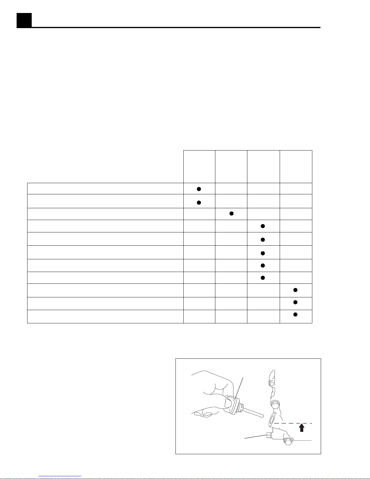
Chart 1 : Approximate Starting Power Requirements
Incandescent lights and appliances such as
irons and hot plates, which use a resistive-type
heating element, require the same wattage to
start and run as is stated on their nameplates.
Fluorescent and mercury lamps require 1.2–2
times their stated wattage to start.
Electrical motors and many types of electrical
tools often require a large starting current. The
amount of starting current depends on the type
of motor and its use.
Most electrical tools require 1.2–3 times their
stated wattage for running.
Loads such as submersible pumps and air
compressors require a very large force to start.
They need as much as 3–5 times the wattage
stated on the nameplate in order to start.
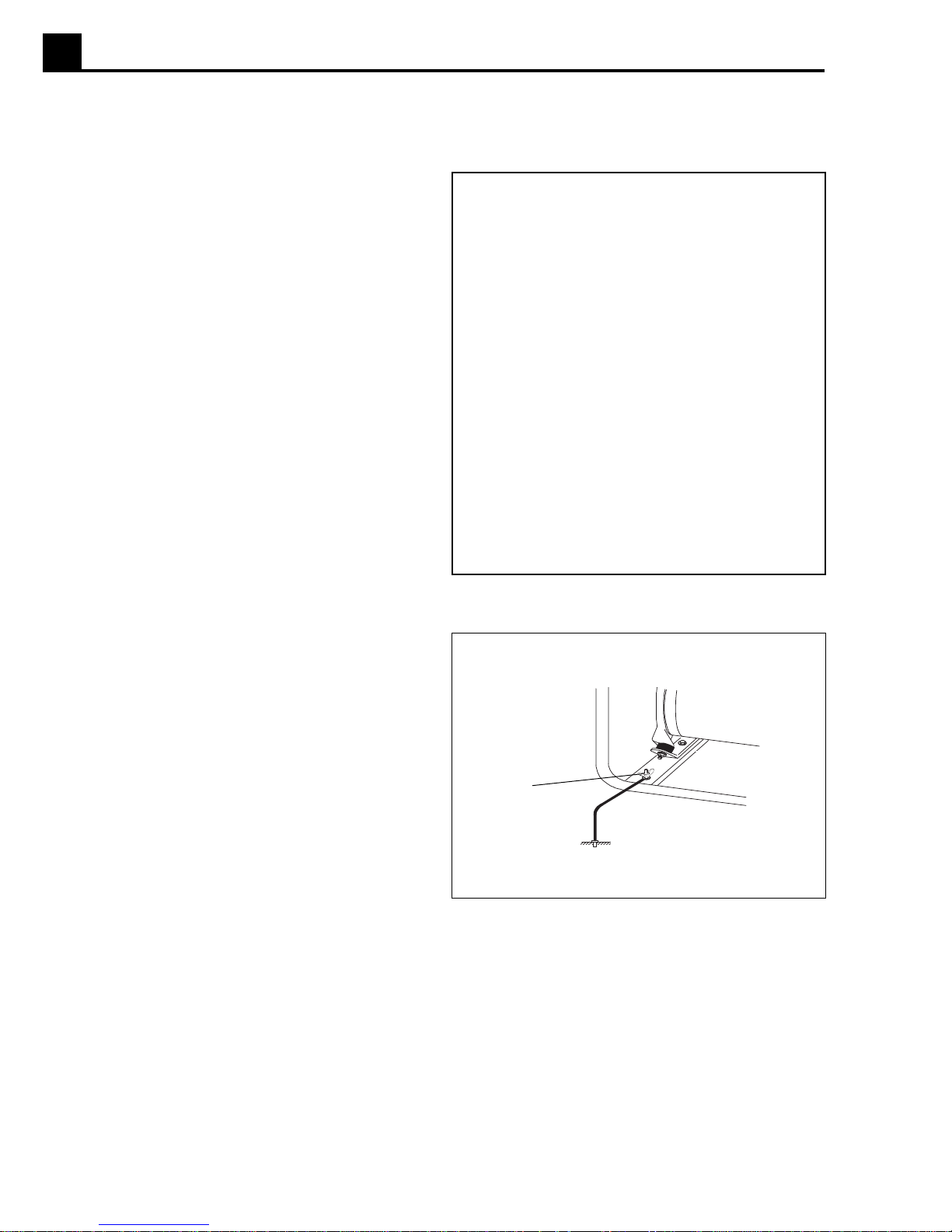
1.9 Grounding the Generator
The generator should be grounded to a good ground
source in compliance with National Electric Code standards and local regulations.
Use #8 wire and secure one end to the ground terminal
(a) provided on the generator frame and the other end to
a suitable ground source.
1.10 Outdoor Operation
Place the generator in an area where it will not be
exposed to rain, snow, or other forms of moisture. Make
sure it is positioned on firm, level ground so it will not slide
or shift. Position engine exhaust away from areas where
people may be present.
a
1001SD02
If operating the generator inside a tunnel or deep trench,
make sure there is adequate ventilation. Precautions
similar to those required when operating indoors may be
necessary.
1A-8
Page 13

G2.5A OPERATION 1A
1.1 1 Indoor Operation
If the generator must be operated indoors, adequate
ventilation or exhaust hoses must be provided. When
venting exhaust fumes, make sure the exhaust piping is
large enough to prevent excessive back pressure to the
engine. Back pressure reduces engine efficiency and
may cause the engine to overheat.
!
DANGER
Exhaust gas from the engine contains poisonous
carbon monoxide gas; exposure to carbon monoxide can cause loss of consciousness and may lead
to death. Never run generator indoors or in an
enclosed area unless adequate ventilation, through
such items as exhaust fans or hoses, is provided.
When operated indoors, steps to prevent fire and explosion such as providing a good earthen ground, removing
all flammable materials near generator, and using only
electric cables in good condition, must be observed. See
Section
Operating Safety.
1.12 Use of Extension Cords
When a long extension cord is used to connect an
appliance or tool to the generator, a voltage loss occurs—
the longer the cord, the greater the voltage loss. This
results in less voltage being supplied to the appliance or
tool and increases the amount of current draw or reduces
performance. A heavier cord with a larger wire size will
reduce the voltage loss.
CAUTION: Operating equipment at low voltage can
cause it to overheat.
Use the chart as a guide for selecting proper cable size.
Use only extension cords rated for outdoor use and
equipped with a third-wire ground.
!
WARNING
Damaged cords can cause electrical shock. Electric
shock can cause serious injury or death. DO NOT
use worn, bare, or frayed cords. Replace damaged
cords immediately.
TABLE 3 Maximum Extension Cord Length
Current Load in Watts Maximum Cord Length in Ft.
Amps 120V 240V #10 #12 #14 #16
2.5 300 600 1000 ft. 600 ft. 375 ft. 250 ft.
5 600 1200 500 ft. 300 ft. 200 ft. 125 ft.
7.5 900 1800 350 ft. 200 ft. 125ft. 100 ft.
10 1200 2400 250 ft. 150 ft. 100 ft.
15 1800 3600 150 ft. 100 ft. 65 ft.
20 2400 4800 125 ft. 75 ft. 50 ft.
1A-9
Page 14

1A OPERATION G2.5A
1.13 Ground Fault Circuit Interrupt (GFI)
The 120V, 20 Amp duplex receptacle (a) is equipped with
a ground fault circuit interrupt (GFI). The GFI shuts off the
power to the receptacle when a ground fault occurs in the
generator or to a piece of equipment attached to the
generator. This GFI also protects the second 120V,
20Amp duplex receptacle
The GFI should be tested for proper operation every time
the generator is used.
(c).
a
d
e
To test GFI:
Start generator. Push TEST button
The RESET button
the receptacle. If the RESET button does not pop out, the
GFI is not working. Do not run generator until the problem
can be corrected. To restore power to receptacle, push
the RESET button in.
If the RESET button pops out during operation, stop the
generator and check it and equipment for defects.
(e) will pop out. Power is now off at
(d) on receptacle in.
1.14 Circuit Breaker Protection
The generator is also protected by a 20 Amp circuit
breaker (b) located on the control panel.
The circuit breaker protects the generator from severe
overloads or short circuits. If the circuit breaker opens,
turn the engine off immediately and determine the cause
before restarting. Check the appliances and tools attached to the generator for defects and make sure their
power requirements do not exceed the power rating of
the generator or the current limit of the receptacles.
When the circuit breaker opens, the breaker button will
pop out. To reset circuit breaker, push button in.
120 VAC 20 AMP
b
c
wc_gr000268
1.15 Before Starting
1. Read and understand safety and operating instructions at beginning of this manual.
2. Read and understand the meanings of all warning and
operating labels.
3. Inspect generator for any signs of damage which may
affect operation or pose a safety hazard. Tighten any
loose nuts or bolts.
4. Check engine oil and fill to recommended level.
Note:
The engine is equipped with an oil alert system.
If the oil level in the engine drops too low the engine
will not start.
5. Fill fuel tank with fresh, regular, unleaded grade
gasoline. DO NOT use an oil/gas mixture. The use of
gasohol or any fuel containing more than 10% ethanol
is not recommended. Consult engine owner’s manual
for complete fuel specifications.
1A-10
Page 15

G2.5A OPERATION 1A
CHOKE
1.16 To Start
c
1
c
2
1015SD03 1015SD04
e
2
e
1
d
1
d
2
f
1005SD47
1.17 To Stop
1005SD49
Before starting, be sure you read and understand all the
safety and operating instructions in this manual.
1. Disconnect all loads from the generator.
2. Open fuel valve by moving lever to the right (c
Note:
position
position
3. Turn engine switch to “ON” (e
4. Pull starter rope (f).
Note:
If engine is cold, move choke lever to closed
(d1).
If engine is hot, set choke to open
(d2).
).
1
If the oil level in the engine is low, the engine
).
1
will not start. If this happens, check oil level and add
oil as needed.
5. As engine warms up move choke lever to OPEN
position (d
6. Allow engine to warm up a few minutes before attaching loads.
).
2
1. Turn off and disconnect all tools and appliances
attached to the generator.
2. Turn engine switch to “OFF” (e
3. Close fuel valve by moving lever to the left (c
Note:
engine switch to "OFF"
To stop engine quickly in an emergency, turn
(e2).
).
2
).
2
1.18 Operating Heavy Loads
Limit operations requiring the maximum rated output
of 2500 W to 20 – 30 minutes. For continuous operation
do not exceed the continuous rated output of 2250 W.
CAUTION: DO NOT exceed the current limit specified
on the control panel for any one receptacle.
1A-11
Page 16
1A OPERATION G2.5A
1.19 Engine Maintenance
The Periodic Maintenance Schedule below lists basic maintenance intervals for the engine and generator. Please
read the detailed maintenance procedures for the engine described in engine Owner’s Manual. This manual was
supplied with the generator. Replacement copies of these manuals can be ordered from WACKER Corporation or
directly from the engine manufacturer.
1.20 New Machines
Change engine oil and replace oil filter after the first 20 hours of operation.
1.21 Periodic Maintenance Schedule
Check engine oil. Fill to correct level.
Check air cleaner.
Clean air cleaner.*
Change engine oil.
Check sediment cup at carburetor.
Clean and adjust spark plug.
Clean spark arrester (optional accessory).
Check shockmounts. Replace when necessary.
Check and adjust valve clearance.*
Clean fuel tank.*
Check condition of fuel line. Replace when necessary.
* Service more frequently in dusty conditions.
Daily
Before
Starting
Every 3
months or
50 hours
Every 6
months or
100 hours
Every year
or 300
hours
1.22 Changing Oil
Drain oil while engine is still warm.
1. Remove oil fill plug (g) and drain plug (h) to drain oil.
2. Install drain plug.
3. Fill engine crankcase with recommended oil up to
level of plug opening (i).
Oil Capacity: 21 oz. (0.6 liters)
4. Install oil filler cap.
Note:
In the interests of environmental protection, place
a plastic sheet and a container under the machine to
collect any liquid which drains off. Dispose of this liquid
in accordance with environmental protection legislation.
1A-12
g
i
h
1005SD53
Page 17

G2.5A OPERATION 1A
1.23 Servicing Air Cleaner
The engine is equipped with a dual element air cleaner—
service frequently to prevent carburetor malfunction.
CAUTION: NEVER run engine without air cleaner.
Severe engine damage will occur.
a
!
WARNING
NEVER use gasoline or other types of low flash
point solvents for cleaning the air cleaner. A fire or
explosion could result.
b
1. Remove wing nut and air cleaner cover (a). Remove
both elements and inspect them for holes or tears.
Replace damaged elements.
2. Foam Element
Wash in solution of mild detergent and warm water.
Rinse thoroughly in clean water. Allow element to dry
thoroughly.
Soak element in clean engine oil and squeeze out
excess oil.
(c)
c
3. Paper element (b)
Tap element lightly to remove excess dirt or blow
compressed air through filter from the inside out.
Replace paper element if it appears heavily soiled.
1.24 Cleaning Sediment Cup
Turn fuel valve off. Remove sediment cup (e) and O-ring
(d). Wash them thoroughly in a nonflammable solvent.
Dry them and reinstall. Turn fuel valve on and check for
leaks.
1001SD12
d
e
1001SD13
1A-13
Page 18
1A OPERATION G2.5A
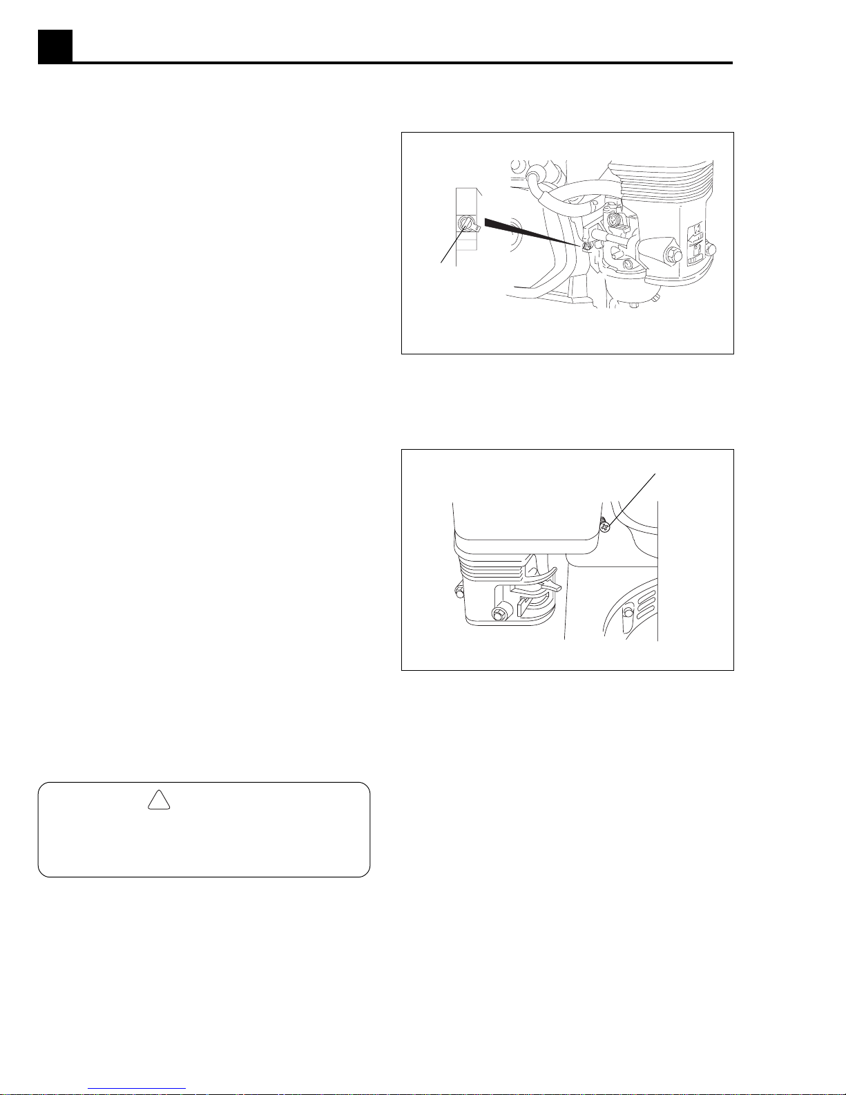
1.25 Carburetor Adjustment
The pilot screw (a) is fitted with a limiter cap to prevent
excessive enrichment of the air-fuel mixture in order to
comply with emission regulations. The mixture is set at
the factory and no adjustment should be necessary. Do
not attempt to remove the limiter cap. The limiter cap
cannot be removed without breaking the pilot screw.
a
1015SD05
1.26 Setting Engine Speed
Generators require a fixed engine speed to maintain the
correct voltage. Engine speed is controlled by a governor
which automatically adjusts to varying loads on the
engine to maintain a constant speed of 3600–3700 rpm.
To set governor speed:
Turn governor speed adjusting screw (j) in or out to
obtain a no-load speed of 3700 rpm.
CAUTION:
low may damage tools and other appliances attached to
the generator.
Setting the governor speed too high or too
1.27 Transporting
!
WARNING
Let engine cool before transporting generator or
storing indoors, to avoid burns or fire hazards.
j
1001SD15
When transporting the generator:
1. Turn the engine fuel valve to the off position.
2. Position the generator level to prevent fuel from
spilling.
3. Secure the generator by tying it down with suitable
rope.
1A-14
Page 19

G2.5A OPERATION 1A
1.28 Storage
Before storing generator for a long period of time:
1. Close the fuel valve and remove and empty sediment
cup under carburetor.
2. Disconnect the fuel line from the carburetor. Place
open end of fuel line into a suitable container and open
fuel valve to drain fuel from tank.
!
WARNING
Gasoline is extremely flammable. Drain fuel tank in
a well-ventilated area. DO NOT drain tank in an area
with flames or sparks.
3. Loosen the drain screw on the carburetor and drain
any remaining fuel from carburetor.
4. Change the engine oil.
5. Remove the spark plug and pour approximately one
tablespoon (1 ounce) of clean engine oil into the
cylinder. Crank the engine a few turns to distribute the
oil to the inside of the cylinder walls.
1.29 Troubleshooting
If engine doesn't start, check that:
1. Engine switch is on "Start".
2. Fuel valves under fuel tank and on engine are open.
3. Fuel tank has fuel.
4. Choke lever is in correct position. Choke should be
closed when starting a cold engine.
5. All loads are disconnected from generator.
6. Spark plug is in good condition.
7. Spark plug cap is tight.
8. Engine oil level is adequate.
If engine starts but there is no power at receptacles,
check that:
1. Circuit breaker is closed.
2. Connector from generator to control panel is tight.
6. Pull the starter rope slowly until resistance is felt and
leave handle in this position. This ensures that the
intake and exhaust valves are closed.
7. Store generator in a clean, dry area.
1A-15
Page 20

1A OPERATION G2.5A
1.30 Wiring Schematic
G
1
5
6
0
7
B
W/Y
B
Y
B/R
20A
120VAC
Wire Colors
B/Y
B - Black W- White
G - Green Y - Yellow
L - Blue Br- Brown
R - Red T - Tan
O - Orange
G/Y
20A
120VAC
BC
G
G/W
B
20A
G/Y
R
1
R
W
2
W
A
1
3
4
1A-16
2
A= Generator
B= Control Box
C= Engine
1= Main Windings
2= Auxiliary Windings
3= Capacitor
4= Rotor Windings
5= Ingnition Switch
6= Oil Level Switch
7= Coil
3
25 uF
400 V
4
B
B
wc_gr000262
Page 21

UNITED KINGDOM
LONDON LEA ROAD Tel. (44)(01992) 707200
Washington Washington/Tyne N37 1LH Tel. (0191) 4 16 63 92
Warrington Winwick Quay, Warrington WA2 8RE Tel. (01925) 57 39 55
Worksop Worksop S81 7BE Tel. (01909) 48 45 06
Redditch Washford, Redditch B98 0DQ Tel. (01527) 2 45 56
Pontypool Pontypool, Gwent NP4 6PD Tel. (01495) 75 05 95
Ashford Ashford, Kent TN23 2NF Tel. (01233) 64 52 27
Exeter Clyst, Honiton, Exeter EX5 2LG Tel. (01392) 6 97 71
Hungerford Hungerford R617 OYX Tel. (01488) 68 14 28
Lanarks Bellshill, Lanarks ML4 3NN Tel. (01698) 84 58 15
WALTHAM CROSS, HERTS EN9 1AW
ÖSTERREICH
1110 WIEN SCHEMMERLSTR.82 Tel. (43) 01-7671515
4050 Traun Wiener Bundesstr. 147 Tel. 07229-73739
9020 Klagenfurt Wiegelegasse 18 Tel. 0463-262716
8054 Graz-Strassgang Kärntner Str. 512 Tel. 0316-281690
6122 Fritzens Innstr. 11 Tel. 05224-51351
5300 Hallwang b. Sbg. Wiener Bundesstr. 17 Tel. 0662-661741
3106 St. Pölten Hnilickastr. 9 Tel. 02742-73170
DEUTSCHLAND
80809 MÜNCHEN PREUSSENSTR. 41 Tel. 089/35 40 21
85757 Karlsfeld (WLZ) Tel. 018131-59780
21109 Hamburg Fax 040/75 73 90 Tel. 040/75 15 66
24145 Kiel Fax 0431/71 46 25 Tel. 0431/71 15 25
23566 Lübeck Fax 0451/62 56 15 Tel. 0451/62 56 19
28307 Bremen-Mahndorf Fax 0421/48 15 36 Tel. 0421/48 15 01
26789 Leer-Bingum Fax 0491/6 25 39 Tel. 0491/6 72 20
30165 Hannover Fax 0511/3 52 49 69 Tel. 0511/3 52 40 61
38112 Braunschweig Fax 0531/31 29 24 Tel. 0531/31 21 80
34233 Fuldatal Fax 0561/81 10 58 Tel. 0561/81 10 59
40721 Hilden Fax 02103/4 69 31 Tel. 02103/3 10 48
41065 Mönchengladbach Fax 02161/4 25 44 Tel. 02161/48 11 41
46485 Wesel Fax 0281/5 16 37 Tel. 0281/8 98 79
45326 Essen Fax 0201/32 13 02 Tel. 0201/31 17 93
48291 Telgte Fax 02504/71 47 Tel. 02504/26 68
49565 Bramsche Fax 05461/49 22 Tel. 05461/6 21 21
44319 Dortmund Fax 0231/21 82 27 Tel. 0231/21 82 26
33659 Bielefeld Fax 0521/40 31 14 Tel. 0521/4 07 77
52355 Düren Fax 02421/6 21 22 Tel. 02421/6 30 51
53842 Troisdorf Fax 02241/4 65 75 Tel. 02241/4 40 31
56218 Mülheim-Kärlich Fax 0261/2 65 55 Tel. 0261/2 65 10
57080 Siegen Fax 0271/31 10 49 Tel. 0271/31 50 55
60388 Frankfurt Fax 069/41 71 89 Tel. 069/42 40 80
35398 Gießen Fax 0641/2 98 19 Tel. 0641/2 22 69
55129 Mainz-Hechtsheim Fax 06131/50 79 80 Tel. 06131/59 20 70
66119 Saarbrücken Fax 0681/85 15 30 Tel. 0681/85 20 11
67133 Maxdorf Fax 06237/50 08 Tel. 06237/72 00
74172 Neckarsulm-Obereisesheim Fax 07132/4 36 19 Tel. 07132/4 36 18
71254 Ditzingen Fax 07156/1 82 04 Tel. 07156/60 54
72336 Balingen-Frommern Fax 07433/3 76 86 Tel. 07433/47 53
76327 Pfinztal Fax 0721/46 86 60 Tel. 0721/46 04 67
77746 Schutterwald Fax 0781/5 97 13 Tel. 0781/5 23 43
78315 Radolfzell Fax 07732/5 65 08 Tel. 07732/5 64 85
79112 Freiburg-Opfingen Fax 07664/5 97 76 Tel. 07664/10 14
89155 Erbach Fax 07305/86 10 Tel. 07305/61 22
88353 Kißlegg-Zaisenhofen Fax 07563/85 73 Tel. 07563/82 76
85716 Unterschleißheim Fax 089/3 17 13 07 Tel. 089/3 10 60 31
85077 Manching Fax 08459/76 02 Tel. 08459/69 97
82538 Geretsried Fax 08171/3 14 09 Tel. 08171/3 12 68
83064 Raubling Fax 08035/39 79 Tel. 08035/22 22
94491 Hengersberg Fax 09901/32 13 Tel. 09901/21 99
93128 Regenstauf Fax 09402/33 66 Tel. 09402/45 01
90765 Fürth-Stadeln Fax 0911/76 34 90 Tel. 0911/76 40 24
95326 Kulmbach Fax 09221/8 44 87 Tel. 09221/26 20
97080 Würzburg Fax 0931/9 81 58 Tel. 0931/9 17 08
63741 Aschaffenburg Fax 06021/8 36 17 Tel. 06021/8 36 16
86167 Augsburg Fax 0821/70 78 58 Tel. 0821/70 22 07
13627 Berlin Fax 030/349 919-12 Tel. 030/349 919-0
13627 Berlin-Nord (Land-Brandenburg) Fax 030/344 13 52 Tel. 030/344 30 47
14974 Genshagen (Berlin-Süd) Fax 03378/81 06 23 Tel. 03378/81 06 21
19061 Schwerin/Görrîes Fax 0385/660 513 Tel. 0385/650 55
01097 Dresden Fax 0351/803 60 91 Tel. 0351/8036090
04430 Blenltz/OT Dölzlg (Leipzig) Fax 034205/5 89 83 Tel. 034205/58982
99428 Nohra (Erfurt) Fax 03643/82 58 28 Tel. 03643/825826
09247 Röhrsdorf (Chemnitz) Fax 03722/50 24 85 Tel. 03722/502 484
39167 Irxleben (Magdeburg) Fax 039204/6 64 78 Tel. 039204/56 78
17033 Neubrandenburg Fax 0395/369 00 41 Tel. 0395/3690040
Fax 089/35 40 23 90
Page 22

UNITED STATES
CORPORATE OFFICE
MENOMONEE FALLS, WI 53052 N92 W15000 ANTHONY AVE. Tel. (262) 255-0500
CANADA
MISSISSAUGA, ONT. L5T 2N6 160 ADMIRAL BLVD. Tel. (905) 795-1661
Calgary, Alta. T2H 2H9 #11, 6115-4 St. S.E. Tel. (403) 255-3336
St. Laurent, Quebec H4R 2C1 3526 Rue Ashby Tel. (514) 337-1708
MEXICO
MEXICO CITY 2A. CERRADA NORTE 147 NO. 20 Tel. (55) 53-53-15-03
Monterrey, Nuevo León Calle Nardo #970, Col. Cementos, C. P. 64520 Tel. (81) 83-31-12-85
C. P. 45010, Zapopan, Jalisco Periférico Poniente No. 2100-Int. F, Tel. (33) 36271499
C. P. 37530 León, Guanajuato Privada Manzanares #103, Fracc.San Isidro de Jerez Tel. (477)7-11-34-35
C. P. 91700 Veracruz, Ver. Miguel Alemán N
COL. SAN MIGUEL AMANTLA 02700 Mexico D.F.
Col. Lomas del Colli
o
. 1001B, Col. Centro Tel. (229)9-35-10-44
ARGENTINA Colectora Oeste de Ruta Panamerica Tel. 5411-4-748-6800
BUENOS AIRES 1611 Km 28.5 Don Torcuato
BRASIL Avda. Arquimedes 1070 Tel. 5511-4582-4333
SÃO PAULO Unidade Autonoma No. 6
Jundiai, São Paulo
CHILE
SANTIAGO El Rosal 5000, Huechuraba, Casilla 130 - Correo 30 Tel. (56) 2-7400014
Antofagasta Orella 975 Tel. (56) 55-227250
Temuco Balmaceda 298 Tel. (56) 45-214425
AUSTRALIA
CLAYTON, VIC. 3169 PO Box 1315 RMDC Tel . (61) 03-95474033
Norwood, S.A. 5067 45 Beulah Road Tel. 08-3622331
Woodridge, QLD 4114 Unit 2, 6-8 Pendrey Court Tel. 07-32089577
Osborne Park, W.A. 6017 Unit P, 69-73 Hector Street Tel. 09-4452911
Auburn, N.S.W. 2144 14 Vore Street Tel. 02-7480366
JAPAN
OHTA-KU, TOYKO 144 2-CHOME 18-1, MINAMI-KAMATA Tel. (81) 03-37329281/5
Hirano-ku, Osaka-shi Miyake Nishi, 4-Chome Tel. 0723 30-0571
Sendai-shi Tachimachi 1-7-21 Tel. 022 284-8032
Fukuoka-shi Sannoh 1-7-1, Hakata-ku Tel. 092 451-1083
MALAYSIA
46150 PETALING JAYA 5. JALAN PJS 11/22 Tel. (03) 7364770
Selangor Darul Ehsan Bandar Sunway
NEW ZEALAND 4A Ponui Place
WIRI-AUCKLAND Mt. Wellington, Auckland Tel. (64) (9) 270 3784
SINGAPORE
JURONG TOWN SINGAPORE 2263 NO. 23, Tuas Ave. 18 Tel. (65) 861-0446
THAILAND 22/197 Pattanakarn Rd. Tel. (66) 2-319-9363/65
BANGKOK 10250 Soi Mooban Panya
www.wackergroup.com
SOUTH AFRICA 1031 KATROL AVE., ROBERTVILLE X10 Tel. H/O Jhb(011) 672-0847
JOHANNESBURG Roodepoort / P.O. Box 2163, Florida 1710, Gauteng.
Durban 10 Kinsman Rd. P.O. Box 420, New Germany 3620 Tel. Dbn(031) 702-3337
Capetown Cor. Beatrix & Carel, Marincowitz St.
P.O. Box 398, Brackenfell 7560 Tel. Cpt(021) 981-2197
CHINA Unit 611-612, 6/F Sunley Centre Tel. (852) 24068613
HONG KONG 9 Wing Yin Street
Wacker Corporation - P. O. Box 9007 - Menomonee Falls, WI 53052-9007 - Tel.: (262)-255-0500 - Fax: (262)-255-0550
Wacker-Werke GmbH & Co. KG - Preußenstraße 41 - 80809 München - Tel.: +49-(0)89-354 02-0 - Fax: +49-(0)89-35 402-390
Kwai Chung, New Territories
0902
 Loading...