

Page 1

5200016122 1.1
www.wackerneuson.com
5200016122
0814
Track Excavator
EZ38
OPERATOR’S MANUAL
Page 2

Documentations
Language Order no.
Operator's Manual
Service Booklet
Spare parts list
Legend
Original Operator‘s Manual
Translation of original Operator‘s Manual x
Edition 1.1
Date 08/2014
Document OM EZ38 us
us 5200016122
de 1000146850
en 1000148392
fr 1000148394
it 1000148395
es 1000148393
de/en/fr 1000304453
de/it/es 1000304454
-
Copyright © 2014 Wacker Neuson Baumaschinen GmbH, Hörsching
Printed in Michigan, USA
All rights reserved, in particular the globally applicable copyright, right of reproduction and right of distribution.
No part of this publication may be reproduced, translated or used in any form or by any means – graphic, electronic
or mechanical including photocopying, recording, taping or information storage or retrieval systems – without prior
permission in writing from the manufacturer.
No reproduction or translation of this publication, in whole or part, without the written consent of Wacker Neuson
Linz GmbH.
Violations of legal regulations, in particular of the copyright protection, will be subject to civil and criminal prosecution.
Wacker Neuson Linz GmbH keep abreast of the latest technical developments and constantly improve their products. For this reason, we may from time to time need to make changes to diagrams and descriptions in this documentation which do not reflect products which have already been delivered and which will not be implemented on
these machines.
Technical data, dimensions and weights are given as an indication only. Responsibility for errors or omissions not
accepted. Non-metric weights and measurements are approximate.
The cover features the machine with possible optional equipment
Pictures and graphics are symbolic representations and can differ from the actual product.
Wacker Neuson Linz GmbH
Flughafenstraße 7
A-4063 Hörsching
Document: OM EZ38 us
Order no.: 5200016122
Page 3

Table of Contents
Table of Contents
EC Declaration of Conformity (Tier IV interim) .................................................................................... EG-1
Declaration of conformity without CE mark on type label (Tier IV interim) .......................................... EG-2
1Foreword
1.1 Operator’s Manual ................................................................................................................................ 1-1
1.2 Warranty and liability ............................................................................................................................ 1-5
2 Safety Information
2.1 Safety Symbols Found in this Manual .................................................................................................. 2-1
2.2 Warranty ............................................................................................................................................... 2-2
2.3 Designated Use .................................................................................................................................... 2-2
2.4 Preparing to use the machine............................................................................................................... 2-3
2.5 Operator and Technician Qualifications and Basic Responsibilities..................................................... 2-6
2.6 Safety instructions Regarding Operation .............................................................................................. 2-6
2.7 Applications with Lifting Gear ............................................................................................................... 2-9
2.8 Attachments........................................................................................................................................ 2-10
2.9 Transport and Towing......................................................................................................................... 2-11
2.10 Safety Guidelines for Maintenance..................................................................................................... 2-11
2.11 Safety Guidelines during using Internal Combustion Engines............................................................ 2-16
3 Introduction
3.1 Machine overview................................................................................................................................. 3-1
3.2 Brief description of the machine ........................................................................................................... 3-2
3.3 Notices and regulations on use ............................................................................................................ 3-4
3.4 Labels ................................................................................................................................................... 3-7
4 Putting into operation
4.1 Cabin/control stand............................................................................................................................... 4-1
4.2 Overview of control elements ............................................................................................................. 4-31
4.3 Indicator lights and warning lights (overview) ..................................................................................... 4-36
4.4 Preparatory work ................................................................................................................................ 4-39
4.5 Starting and stopping the engine........................................................................................................ 4-43
5Operation
5.1 Steering system.................................................................................................................................... 5-1
5.2 Accelerator actuation............................................................................................................................ 5-1
5.3 Brakes .................................................................................................................................................. 5-2
5.4 Travel operation.................................................................................................................................... 5-3
5.5 Differential lock ..................................................................................................................................... 5-8
5.6 Lights/signalling system........................................................................................................................ 5-8
5.7 Wiper/wash system ............................................................................................................................ 5-10
5.8 Heating, ventilation and air conditioning system................................................................................. 5-11
5.9 Operating hydraulics........................................................................................................................... 5-13
5.10 Attachments........................................................................................................................................ 5-38
5.11 Work operation ................................................................................................................................... 5-42
5.12 Emergency lowering ........................................................................................................................... 5-47
5.13 Options ............................................................................................................................................... 5-48
5.14 Decommissioning and putting the machine back into operation......................................................... 5-57
5.15 Final decommissioning of machine..................................................................................................... 5-59
6 Transport
6.1 Towing the machine ............................................................................................................................. 6-1
6.2 Loading the machine ............................................................................................................................ 6-3
6.3 Transporting the machine..................................................................................................................... 6-6
OM EZ38 us 1.1 * ez38us1_1IVZ.fm I-1
Page 4

7 Maintenance
7.1 Important information on maintenance ................................................................................................. 7-1
7.2 Maintenance overview .......................................................................................................................... 7-2
7.3 Fluids and lubricants........................................................................................................................... 7-10
7.4 Maintenance accesses ....................................................................................................................... 7-14
7.5 Cleaning and maintenance on or with the machine............................................................................ 7-19
7.6 Lubrication work.................................................................................................................................. 7-22
7.7 Fuel system ........................................................................................................................................ 7-27
7.8 Engine lubrication system................................................................................................................... 7-33
7.9 Cooling system ................................................................................................................................... 7-35
7.10 Air filter................................................................................................................................................ 7-38
7.11 V-belt/toothed belt............................................................................................................................... 7-41
7.12 Hydraulic system ................................................................................................................................ 7-42
7.13 Electrical system................................................................................................................................. 7-47
7.14 Heating, ventilation and air conditioning system................................................................................. 7-49
7.15 Washer system ................................................................................................................................... 7-49
7.16 Axles/Traveling drive .......................................................................................................................... 7-50
7.17 Brake system ...................................................................................................................................... 7-50
7.18 Tires/Tracks ........................................................................................................................................ 7-50
7.19 Maintenance of attachments............................................................................................................... 7-53
7.20 Maintenance of options....................................................................................................................... 7-53
7.21 Exhaust gas treatment........................................................................................................................ 7-54
7.22 Machine preservation ......................................................................................................................... 7-54
8 Troubleshooting
8.1 Diesel engine malfunctions................................................................................................................... 8-1
8.2 Malfunctions of the traveling drive ........................................................................................................ 8-2
8.3 Malfunctions of the hydraulic system.................................................................................................... 8-2
8.4 Malfunctions of the electrical system .................................................................................................... 8-3
8.5 Troubleshooting the air conditioning..................................................................................................... 8-4
8.6 Malfunctions of attachments ................................................................................................................. 8-4
9 Specifications
9.1 Models and trade names ...................................................................................................................... 9-1
9.2 Engine................................................................................................................................................... 9-1
9.3 Traveling drive/axles............................................................................................................................. 9-2
9.4 Brakes................................................................................................................................................... 9-2
9.5 Tracks ................................................................................................................................................... 9-2
9.6 Steering system .................................................................................................................................... 9-2
9.7 Operating hydraulics............................................................................................................................. 9-3
9.8 Electrical system................................................................................................................................... 9-4
9.9 Tightening torques ................................................................................................................................ 9-6
9.10 Coolant ................................................................................................................................................. 9-7
9.11 Noise emissions.................................................................................................................................... 9-7
9.12 Vibration................................................................................................................................................ 9-8
9.13 Weight................................................................................................................................................. 9-11
9.14 Payload/stability.................................................................................................................................. 9-13
Index
Index ..............................................................................................................................................................S-1
I-2 OM EZ38 us 1.1 * ez38us1_1IVZ.fm
Page 5

EC Declaration of Conformity
According to Machine Directive 2006/42/EC, appendix II A
Manufacturer
Wacker Neuson Linz GmbH
Flughafenstr. 7
A-4063 Hörsching
Product
Machine designation: Hydraulic excavator
Machine model: EZ38
Serial no.: ______________
Output (kW): 21.4 kW
Measured sound power level: 94 dB (A)
Guaranteed sound power level: 95 dB (A)
Conformity assessment procedure
Notified body according to Directive 2006/42/EC, appendix XI:
DGUV Test
Prüf- und Zertifizierungsstelle
Fachbereich Bauwesen
Landsberger Str. 309
D-80687 Munich
Distinguishing EU number 0515
Notified body according to Directive 2000/14/EC, appendix VI:
TÜV SÜD Industrie Service GmbH
Westendstr. 199
D-80686 Munich
Directives and standards
We hereby declare that this product corresponds to the relevant regulations and requirements of the
following Directives and standards:
2006/42/EC, 2004/108/EC, 2002/44/EC, 2005/88/EC, 2000/14/EC;
DIN EN ISO 12100:2010, DIN EN 474-1:2006+A1:2009, DIN EN 474-5:2012,
DIN EN ISO 3471:2010, DIN EN ISO 3744:2010, DIN EN ISO 3449:2008, DIN EN ISO 13849-2:2012
Technical director
Responsible for documentation
Hörsching,
Place, date
Declaration of conformity
Declaration of conformity
EC Declaration of Conformity (Tier IV interim)
OM EZ38 us 1.1 * ez38konf.fm EG-1
Page 6

Declaration of conformity without CE mark on type label
Declaration of conformity
Manufacturer
Wacker Neuson Linz GmbH
Flughafenstr. 7
A-4063 Hörsching
Product
Machine designation: Hydraulic excavator
Machine model: EZ38
Serial no.: ______________
Output (kW): 21.4 kW
Measured sound power level: 94 dB (A)
Guaranteed sound power level: 95 dB (A)
Directives and standards
We hereby declare that this product corresponds to the relevant regulations and requirements of the
following Directives and standards:
2006/42/EC, 2004/108/EC, 2002/44/EC, 2005/88/EC, 2000/14/EC;
DIN EN ISO 12100:2010, DIN EN 474-1:2006+A1:2009 (except 7.3), DIN EN 474-5:2012,
DIN EN ISO 3471:2010, DIN EN ISO 3744:2010, DIN EN ISO 3449:2008, DIN EN ISO 13849-2:2012
Technical directorResponsible for documentation
Hörsching,
Place, date
(Tier IV interim)
EG-2 OM EZ38 us 1.1 * ez38konf.fm
Page 7

Table of Contents
Index
Foreword
1 Foreword
1.1 Operator’s Manual
Notices on this Operator’s Manual
If the machine is equipped with a cabin, the compartment behind the seat
is used for storing the Operator’s Manual.
If the machine is equipped with a canopy, the compartment under the seat
is used for storing the Operator’s Manual.
A document box on the headliner is available as an option for the cabin.
This Operator’s Manual contains important information on how to work
safely, correctly and economically with the machine. Therefore, it aims not
only at new personnel, but it also serves as a reference for experienced
personnel.
Furthermore, the reliability and the service life of the machine will be
increased by following the instructions in the Operator’s Manual. This is
why the Operator’s Manual must be kept at hand in the machine.
The operator must carefully read and understand the Operator’s Manual
before starting up, servicing or repairing the machine.
This Operator’s Manual will help to familiarize yourself more easily with
the machine, thereby enabling you to use it more safely and efficiently.
This Operator’s Manual does not include special superstructures.
Please contact your dealer if you require more information on the machine
or the Operator’s Manual.
1
OM EZ38 us 1.1 * ez38v100.fm 1-1
Page 8

1
Information
Environment
Explanation of symbols and abbreviations
Explanation of symbols
• Identifies a list
- Identifies a subdivision of a list
➥ Description of a result
1. Identifies an activity
Follow the order of the activity!
2. Continuation of an activity
Follow the order of the activity!
A Identifies an alphabetical list
B Continuation of an alphabetical list
Cross references: see page 1-1 (page)
Cross references: 7 (pos. no. or table no.)
Cross references: Fig. 5 (fig. no. 1)
Cross references: – see chapter “5 Operation” on page 5-1
(see chapter)
Cross references: – see “Operation” on page 5-1 (-see text)
Identifies an information that, when followed, provides for a more efficient
and economical use of the machine.
Failure to observe the instructions identified by this symbol can cause
damage to the environment.
1-2 OM EZ38 us 1.1 * ez38v100.fm
Page 9

Abbreviations
TOPS = Tip Over Protective Structure
1
ROPS =
FOPS = Falling Objects Protective Structure
FGPS = Front Guard Protective Structure
AUX = Auxiliary hydraulic circuit
B=Width
NE = Nominal width
PS = Stabilizer blade
LS = Stick
VDS = Vertical Digging System
HSWS = Hydraulic Easy Lock quickhitch
s/h = Service hours
Pos. = Position
Fig. = Figure
e.g. = for example
Roll Over Protective Structure (without losing contact with
the ground)
Exhaust gas standards
approx. = approximately
=
max. = maximum
min. = minimum
The machine can be equipped with an American Tier IV interim or Tier IV
final engine, depending on the destination country. Both engine variants
are described separately if there are engine-specific differences
(regarding operation, for example).
OM EZ38 us 1.1 * ez38v100.fm 1-3
Page 10

1
Conversion table
The rounded imperial values are indicated in brackets, for example 1060
cm³ (64.7 in³).
Volume unit
1 cm³ (0.061 in³)
1 m³ (35.31 ft³)
1 ml (0.034 US fl.oz.)
1 l (0.26 gal)
1 l/min (0.26 gal/min)
Unit of length
1 mm (0.039 in)
1 m (3.28 ft)
Weight
1 kg (2.2 lbs)
1 g (0.035 oz)
Pressure
1 bar (14.5 psi)
1 kg/cm² (14.22 lbs/in²)
Force/output
1 kN (224.81 lbf)
1 kW (1.34 hp)
1 PS (0.986 hp)
Torque
1 Nm (0.74 ft.lbs.)
Speed
1 kph (0.62 mph)
Acceleration
1 m/s² (3.28 ft/s²)
1-4 OM EZ38 us 1.1 * ez38v100.fm
Page 11

1.2 Warranty and liability
Exemption from warranty and liability
Warranty
Warranty claims can be made only if the conditions of warranty have been
observed. They are included in the General Conditions of Sales and
Delivery for new machines and spare parts sold by the dealers of Wacker
Neuson Linz GmbH. Furthermore, all instructions in this Operator’s
Manual must be observed.
Have the maintenance on or with the machine, delivery inspection and the
entries in the service booklet performed by an Wacker Neuson service
center, otherwise warranty claims will not be acknowledged.
Liability
• Modifying Wacker Neuson products and fitting them with additional
equipment and attachments that are not included in our delivery
program requires Wacker Neuson’s written authorization, otherwise
warranty and product liability for possible damage caused by these
modifications shall not be applicable.
• The safety of the machine can be negatively affected by performing
machine modifications without proper authority and by using spare
parts, equipment, attachments and optional equipment that have not
been checked and released by Wacker Neuson GmbH. Warranty and
product liability for possible damage caused by these modifications
shall not be applicable.
• Wacker Neuson Linz GmbH shall not be liable for injury and/or
damage to property caused by failure to observe the safety instructions
and the Operator’s Manual, and by the negligence of the duty to
exercise due care when:
- handling
- operating
- servicing and performing maintenance on or with the machine and
- repairing the machine. This is also applicable in those cases in which
special attention has not been drawn to the duty to exercise due
care, in the safety instructions as well as in the Operator’s and
maintenance manuals.
- Read and understand the Operator’s Manual before starting up,
servicing or repairing the machine. Observe all safety instructions.
1
OM EZ38 us 1.1 * ez38v100.fm 1-5
Page 12

1
Notes:
1-6 OM EZ38 us 1.1 * ez38v100.fm
Page 13

2 Safety Information
DANGER
WARNING
CAUTION
NOTICE
2.1 Safety Symbols Found in this Manual
This is the safety alert symbol. It is used to alert you to potential personal
hazards.
• Obey all safety messages that follow this symbol.
DANGER indicates a hazardous situation which, if not avoided, will
result in death or serious injury.
Consequences in case of non-observance.
► Obey all safety messages that follow this symbol to avoid injury or
death.
WARNING indicates a hazardous situation which, if not avoided,
could result in death or serious injury.
Consequences in case of non-observance.
► Obey all safety messages that follow this symbol to avoid possible
injury or death
CAUTION indicates a hazardous situation which, if not avoided,
could result in minor or moderate injury.
Consequences in case of non-observance
► Obey all safety messages that follow this symbol to avoid possible
minor or moderate injury.
NOTICE indicates a situation which, if not avoided, could result in property
damage.
Note: Contains additional information important to a procedure.
OM EZ38 us – 1.1* * Sicherheit(us).fm 2-1
Page 14

Information
Environment
2.2 Warranty
2.3 Designated Use
Information identifies an instruction that, when followed, provides for a
more efficient and economical use of the machine.
Failure to observe the instructions identified by this symbol can result in
damage to the environment. The environment is in danger if
environmentally hazardous material, such as waste oil, is not subject to
proper use or disposal.
Warranty claims must be submitted to your Wacker Neuson dealer only.
1. In accordance with its designated use, the machine may be used
ONLY for moving earth, gravel, coarse gravel or ballast and rubble. It
may also be used for working with the attachments approved in the
“Fields of Application” chapter.
2. No other applications are designated for the use of the machine.
Wacker Neuson will not be liable for damage resulting from use other
than mentioned above. The operator alone will bear the risk.
3. “Designated use” also includes observing the instructions set forth in
this Operator’s Manual and observing the maintenance schedule.
4. Machine safety can be negatively affected by performing machine
modifications without proper authority and by using spare parts,
equipment,
attachments and optional equipment which have not been checked
and released by Wacker Neuson. Wacker Neuson will not be liable for
damage resulting from unapproved parts or unauthorized
modifications.
5. Wacker Neuson shall not be liable for personal injury and/or damage to
property caused by failure to observe the safety instructions on labels
and in this Operator’s Manual, and by the negligence of the duty to
exercise due care when:
• transporting the machine
• operating the machine
• servicing the machine and performing maintenance on or with the
machine
• repairing the machine
This is also applicable when special attention has not been drawn to the
duty to exercise due care.
1. Read and understand this Operator’s Manual before starting, moving,
operating, servicing or repairing the machine. Observe all safety
instructions.
2. The machine shall NOT be used for transport jobs on public roads!
2-2 OM EZ38 us – 1.1* * Sicherheit(us).fm
Page 15

2.4 Preparing to use the machine
Conditions for use
• The machine has been designed and built in accordance with state-of-
the-art standards and recognized safety regulations. Nevertheless, its
use can constitute a risk to the operator or to third parties, or cause
damage to the machine and to other material property.
• Read and follow this Operator’s Manual and other manuals that
accompany the machine.
• The machine must only be used in accordance with its designated use
and the instructions set forth in this Operator’s Manual.
• The machine must only be used by qualified operators who are fully
aware of the risks involved in operating the machine.
• Do not start, move or operate a damaged or malfunctioning machine.
Any mechanical dysfunctions, especially those affecting the safety of
the machine, must be repaired immediately. Only qualified technicians
shall determine how to move a damaged or malfunctioning machine to
a safe place for diagnoses and repair.
• The operator/machine owner commits himself to operate and keep the
machine in serviceable condition and, if necessary or required by law,
to require the operating or servicing persons to wear protective clothing
and safety equipment
Operator training and knowledge
• Always keep this Operator’s Manual and other manuals that
accompany the machine in their storage compartment provided in the
operator station on the machine. Immediately replace an incomplete or
illegible Operator’s Manual.
• All persons working on or with the machine must read and understand
the safety information in this Manual before beginning work. This
applies especially to persons working only occasionally on the
machine, such as performing set-up or maintenance tasks.
• Follow, and instruct the operator in, legal and other mandatory regula-
tions relevant to accident prevention and environmental
protection.These may include handling hazardous substances, issuing
and/or wearing personal protective equipment, or obeying traffic
regulations.
• The operator/machine owner must regularly ensure that all persons
entrusted with operation or maintenance of the machine are working in
compliance with this Operator's Manual and are aware of the risks and
safety factors of the machine.
Preparing for use
• Before starting up the machine, ALWAYS inspect the machine to make
sure that it is ready for safe work and travel operation.
• Wear close-fitting work clothes that do not hinder movement. Tie back
long hair and remove all jewelry (including rings).
OM EZ38 us – 1.1* * Sicherheit(us).fm 2-3
Page 16
Modifications and spare parts
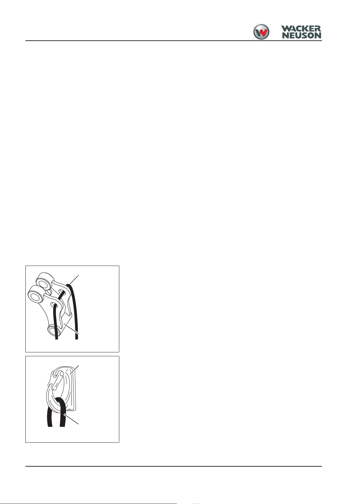
Fig. 1Lifting gear – joint rod
Lifting gear
(joint rod)
Sling
Fig. 2Load hook
Lifting gear
Load hook
• NEVER make any modifications, additions or conversions to the
• Spare parts must comply with the technical requirements specified by
• The operator/machine owner commits himself to operate and keep the
• In the event of safety-relevant modifications or changes on the
• Safety-relevant damage or malfunctions of the machine must be
Applications with lifting gear
Lifting gear applications are procedures involving raising, transporting and
lowering loads with the help of slings and load-securing devices (e.g.
ropes, chains).
No applications with lifting gear under any circumstances!
Machines with a maximum authorized lifting capacity of over 1000 kg
(2,205 lbs.) or an overturning moment of over 40,000 Nm (29,500 ft.lbs.)
may be used for lifting gear applications if the following conditions are
fulfilled:
• Acoustic and optical warning device
• Load holding control valve – see chapter 3.17 “Load holding control
• Proper equipment for slinging and securing the load must be available
• The lift capacity table must be observed – see chapter 6 Specifications
machine and its superstructures (for example, cab, etc.), or the
machine’s attachments, without the approval of Wacker Neuson! Such
modifications may affect safety and/or machine performance. This also
applies to the installation and adjustment of safety devices and valves,
as well as to welding work on load-bearing elements.
Wacker Neuson. Contact your Wacker Neuson dealer for assistance.
machine in perfect condition, and, if necessary or required by law, to
require the operating or servicing persons to wear protective clothing
etc.
machine or of its behavior, stop the machine immediately and report
the malfunction to the competent authority/person.
rectified immediately.
– see chapter 3.20 Safe load indicator (option) on page 3-72
valve” safety feature (option) on page 3-65
(joint rod enabling loads to be picked up, Powertilt unit with load hook).
on page 6-1.
- Get informed on and follow the legal regulations of your country.
2-4 OM EZ38 us – 1.1* * Sicherheit(us).fm
Instructions on fastening loads
• The help of an accompanying person is necessary for securing and
detaching the load.
• The load must be secured so as to prevent it from falling or slipping.
• Fasten the lifting gear so that it is not possible to unhook the sling
unintentionally.
• Position the lifting gear ensuring the sling is not deflected by other
parts.
• Do not use any lifting gear and slings that are damaged or not sufficiently dimensioned.
• The lifting gear must be designed to withstand the loads that can arise
in the different positions of the work equipment or parts of the boom.
Lateral loads and diagonal tensile forces must also be taken into
account.
Page 17

• The lifting gear must be checked regularly by a technician, at least
once a year.
• Replace damaged lifting gear immediately.
• Fasten lifting gear and slings avoiding danger (rotating parts, crushing
or shearing) for the person securing the load. Furthermore, neither
must the work equipment be affected by the lifting gear, nor must the
functions of the lifting gear be affected by external influences (e.g. dirt
that cannot be removed by simple means).
• Do not place slings over sharp edges.
• Always wear protective gloves and a hard hat when working with lifting
gear and slings.
• The persons attaching or securing loads may approach the boom from
the side only, and only after the machine operator has given his
permission. The machine operator may give his permission only after
the machine is at a standstill and the work attachment no longer
moves!
General instructions
• Staying under suspended loads, in the danger zone or under the
machine's attachment is prohibited.
• The machine operator and the person attaching or securing the load
must have visual contact.
• Persons guiding the load or securing it must stay in visual contact with
the machine operator! Should this not be possible, ask another person
to guide.
• The machine operator must guide the load the nearest possible to the
ground and avoid any oscillating or swinging movements!
• The machine may be traveled with a raised load only if the path of the
machine is level!
• The machine operator must not raise loads over persons.
• The machine operator may not leave his seat as long as the load is
raised.
OM EZ38 us – 1.1* * Sicherheit(us).fm 2-5
Page 18

2.5 Operator and Technician Qualifications and Basic Responsibilities
Operator/machine owner responsibility
• Only allow trained and experienced individuals to travel, maintain, or
repair the machine. NEVER let unauthorized or underaged persons
operate with the machine.
• Clearly and unequivocally define the individual responsibilities of the
operator and technician for operation, maintenance, and repair.
• Define the machine operator’s responsibilities on the job site and for
observing traffic rules. Give the operator the authority to refuse instructions by third parties that are contrary to safety.
• Do not allow persons to be trained or instructed by anyone other than
an experienced person. Also, NEVER allow persons taking part in a
general training course to work on or with the machine without being
supervised by an experienced person.
• Before working on or with the machine, remove jewelery, such as
rings, wristwatches, bracelets etc., and tie back long hair and do not
wear loose-fitting garments, such as unbuttoned or unzipped jackets,
ties or scarves.
• Injury can result from being caught up in the machinery or from rings
catching on moving parts!
Repair person qualifications
• Work on the electric system and equipment, on the undercarriage and
the steering and brake systems can be performed only by skilled
individuals who have been specially trained for such work.
• Work on the hydraulic system of the machine must be performed only
by a technician with special knowledge and experience in hydraulic
equipment.
2.6 Safety instructions Regarding Operation
Preparing for use
• The machine must only be used in technically perfect condition in
accordance with its designated use and the instructions set forth in the
Operator's Manual, and only by safety-conscious persons who are fully
aware of the risks involved in operating the machine. Any functional
disorders, especially those affecting the safety of the machine, must
therefore be rectified immediately!
• Before starting up the machine, inspect the machine for safety in work
and road operation!
• In addition to the Operator's Manual, observe and instruct the operator
in all other generally applicable legal and other mandatory regulations
relevant to accident prevention and environmental protection.
• These compulsory regulations may also deal with handling hazardous
substances, issuing and/or wearing personal protective equipment, or
traffic regulations.
• With regard to specific operational features, e.g. those relevant to job
organization, work sequences or the persons entrusted with the work,
supplement the Operator's Manual by corresponding instructions,
including those relevant to supervising and reporting duties.
2-6 OM EZ38 us – 1.1* * Sicherheit(us).fm
Page 19

Starting and stopping
• Careful and prudent working is the best way to avoid accidents!Keep
the machine clean. This reduces the risk of fire hazards (such as from
combustible materials like rags), and reduces the risk of injury or
operational accidents that can be caused by dirt build-up on the travel
pedals or foot rests and steps.
• Observe all safety, warning, and informational signs and labels on the
machine.
• Start and operate the machine from the seat only.
• The operator must sit in the seat, fasten and adjust the seat belt before
putting the machine into operation.
• Always adjust the seat position before starting work. Never change the
seat position when traveling or working!
• Make sure that all safety devices are properly installed and functional
before starting work.
• Before putting the machine/attachment into operation (startup/moving),
make sure that no one in the immediate vicinity will be at risk.
• Perform starting and stopping procedures according to this Operator’s
Manual.
• Observe all indicator lights.
• Do not use starting fluid (for example, ether) especially in those cases
in which a heater plug (intake air pre-heating) is used at the same time.
• Make sure the control levers, the signaling and the light systems are
functional before operating the machine, and also before restarting
after an interruption of work.
• Fold up the control lever base before releasing the seat belt in order to
avoid unintentional operation.
Job site awareness
• Familiarize yourself with the surroundings and circumstances of the
work site before beginning work. Be aware of:
- obstacles in the working and traveling area
- the soil bearing capacity
- any necessary barriers separating the work site from public roads
• Always keep at a safe distance from the edges of building pits and
slopes.
• Look out for the following when working in buildings or in enclosed
areas:
- height of the ceiling/clearances
- width of entrances
- maximum load of ceilings and floors
- sufficient room ventilation—risk of carbon monoxide poisoning!
• Observe the danger zone. See “Danger zone awareness”.
• Use the rearview mirror to stay aware of job site obstacles and
personnel.
• Always switch on the work lights in conditions of poor visibility and after
dark. However, make sure that motorists of public roads will not be
temporarily blinded by the work lights.
• Provide additional lighting on the job site if the lights of the machine are
not sufficient for performing work safely.
OM EZ38 us – 1.1* * Sicherheit(us).fm 2-7
Page 20

Danger zone awareness
Operating the machine
• The danger zone is the area in which persons are in danger due to the
movements of the machine, work equipment, additional equipment, or
material.
• The danger zone also includes the area affected by falling material,
equipment or construction debris. The danger zone must be extended
by 0.5 m (20 inches) in the immediate vicinity of buildings, scaffolds, or
other elements of construction.
• Seal off the danger zone if it is not possible to keep a safe distance.
Stop work immediately if persons do not leave the danger zone in spite
of warnings!
• Never operate the machine if you are standing on the ground.
• Operate the machine ONLY when you are seated and you have
fastened your seat belt. Stop the engine before releasing the seat belt.
• During operation on slopes, travel or work uphill or downhill. If traveling
across a slope cannot be avoided, bear in mind the tilting limit of the
machine. Always keep the attachments/work equipment close to the
ground. This also applies to traveling downhill. During traveling or
working across a slope, the load must be on the uphill side of the
machine.
• On sloping terrain, adapt your travel speed to the prevailing ground
conditions.
• Never get on or off a moving machine, and do not jump off the
machine.
• The travel control levers require practice before an operator becomes
familiar with the control response. Therefore, adjust the travel speed to
your abilities and the surroundings.
• During traveling across a slope with the telescopic undercarriage
extended, position the boom facing down the slope, and the bucket
about 10–20 cm (4–8’’) above the ground. This will help to minimize
the possibility of personal injuries and equipment damage caused by a
hydraulic hose/connector failure in the telescopic undercarriage
actuation system. The weight of the machine will cause the undercarriage to retract to the narrow configuration if hydraulic system pressure
decreases due to lost fluid.
• Install a front guard when working in areas with a risk of objects falling
from the front (e.g. demolition work).
• On sloping terrain always adapt your travel speed to the prevailing
ground conditions! Never change to lower gear on a slope but always
before reaching it!
Carrying passengers
• Do not transport people on the machine or in the attachment.
• Never install a man basket or a working platform to the machine.
Mechanical integrity
• Take the necessary precautions to make sure the machine is used
only when in a safe and serviceable state.
2-8 OM EZ38 us – 1.1* * Sicherheit(us).fm
Page 21

• Operate the machine ONLY if all protective and safety-oriented
devices (ROPS, removable safety devices, soundproofing elements,
mufflers, etc.) are in place and fully functional.
• Check the machine before entering the cab to operate the machine for
visible damage and defects. Report any changes, including changes in
the machine’s function and response, to your supervisor immediately!
• If the machine is functioning unpredictably, stop the machine immedi-
ately, lock it, and report the malfunction to a qualified tecnician or
supervisor. Safety-relevant damage or malfunctions of the machine
must be rectified immediately.
Traveling
• During traveling on or in public areas, observe all applicable regula-
tions. Make sure beforehand that the machine is in compliance with
these regulations.
• Installed work lights must NOT be used for travel.
• During crossing underpasses, gates, bridges and tunnels, or when
passing under overhead lines, make sure the clearance height and
width are sufficient to avoid contact.
• Empty the bucket before traveling on public roads.
2.7 Applications with Lifting Gear
General information
• Craning applications are procedures involving raising, transporting and
• The excavator may be used for applications with lifting gear ONLY if
Safety criteria
• When used for craning applications, the machine must meet the
• In addition, a safe load indicator is required for machines bearing loads
Conditions for safe operation
• Secure the load to prevent it from falling or slipping. Install an OSHA-
• Have loads fastened, and crane operators instructed, by a qualified
lowering loads with the help of slings and load-securing devices (for
example, ropes and tracks). In doing so, the help of persons is
necessary for securing and detaching the load. This applies, for
example, to lifting and lowering pipes, shaft rings or containers.
the prescribed safety devices are in place and functional.
following criteria:
- Proper equipment for slinging and securing the load
- Proper lift capacity per tables in this Operator’s Manual
of over 1000 kg (2,205 lbs.) or an overturning moment of over 40000
Nm (29,477 ft.lbs.).
approved load hook after removing the bucket or other approved
attachment to provide a secure attachment point for the lifting sling,
track, or cable.
person competent in raning operation and standard hand signals. The
person giving instructions to the operator must be within sight of the
operator during load attachment and load disconnection.
OM EZ38 us – 1.1* * Sicherheit(us).fm 2-9
Page 22

• The load shall be kept as close to the surface as practical to accomplish the craning operation. The operator shall gently move the controls
and machine to avoid swing or oscillating motion of the load. A tether
line is recommended to dampen the tendency of the load to swing or
oscillate during the craning operation.
• Machine travel with a raised load must be done very carefully on a
level surface moving very slowly to avoid sudden motion that can
cause swinging or oscillating motion of the load.
• The person(s) attaching the load to the excavator shall approach only if
the operator is in visual contact with them. No one shall approach the
machine or attempt to attach the load until the excavator has stopped
and the operator has signaled for the attachment.
2.8 Attachments
General information regarding attachments
• Prior to traveling remove all attachments which cannot be secured in
compliance with the legal regulations of your country.
• The machine operating characteristics including steering vary with
different option attachments and counter weights. The operator shall
be familiar with the variations and act accordingly.
• Use only approved attachments and connecting hardware.
• Attach and remove attachments carefully to avoid damage and
potential injury.
• Attach and remove attachments carefully to avoid damage and
potential injury.
• Confirm that the attachment has been properly and securely attached
to the machine according to the instructions. Before using the
attachment, the operator shall confirm that the attachment performs
correctly in response to control actuation.
• Do not attach the attachment with the engine running and the machine
moving.
• Before putting the machine/attachment into operation (startup/moving),
make sure that no one in the immediate vicinity will be at risk.
• Before leaving the seat, always secure the machine against unintentional movement and unauthorized use. Lower the attachments to the
ground.
• Mount the attachments only if the engine and the traveling drive have
been stopped.
• Especially when traveling or operating machines equipped with a
quickhitch for the attachments, make sure the attachment is securely
locked in the quickhitch. The lock pin must be visible on either side of
the bores on the attachment. Check before starting work.
Installation notes
• Couple and uncouple hydraulic hoses/lines (hydraulic quick couplers) only if the engine
is stopped and the controls actuated to release the hydraulic pressure remaining in the
circuit. Follow the operating instructions for releasing the pressure.
• Operate the machine only if all protective devices for the attachments have been
installed and are functional, and if all brake, light and hydraulic connections have been
connected.
• If an optional attachment is installed, make sure that all lights and associated indicator
lights are installed and functional.
2-10 OM EZ38 us – 1.1* * Sicherheit(us).fm
Page 23

• The lock pin of the quick hitch attachment shall be visible at each end of the pin to
confirm that the attachment is securely locked in place. The operator shall perform a
check operation to confirm the latching integrity before operating at a production pace.
• Prior to fitting attachments to the stick (the mobile extension of the boom), secure the
control lever of the hydraulic control unit against unintentional movement. Raise the left
arm rest to avoid unintentional activation for the ISO/SAE operating mode. Avoid
actuating the right hand control if the alternative control mode is selected.
2.9 Transport and Towing
Towin g
The machine must be towed, loaded and transported according to the
procedures described within this Operator’s Manual.
Transporting
• The transporting vehicle must have sufficient load capacity and
platform size to safely transport the machine. Refer to section 6 of this
manual to determine the physical characteristics of the machine before
loading and transporting.
• Use OSHA-approved straps, chains or cables to securely fastened the
machine to the surface of the transport.
• Use the tie down points provided on the load surface of the transport.
• Attach the tie down devices to the excavator at the designated tie down
points.
• Confirm that the excavator tie down procedures will prevent sideways,
forward, rearward and upward motion of the excavator in the event the
transport vehicle is involved in an incident or sudden avoidance
maneuver.
2.10 Safety Guidelines for Maintenance
General maintenance notes
• Adhere to prescribed intervals or those specified in this Operator’s
Manual for routine checks/inspections and maintenance on or with the
machine.
• For inspection and maintenance on or with the machine, ensure that all
tools and workshop equipment are capable of performing the tasks
prescribed. Do not use malfunctioning or broken tools. Use certified
measuring devices that are routinely calibrated for accuracy (torque
wrench, pressure gauge, ammeter, etc.).
• Replace hydraulic hoses within stipulated and appropriate intervals
even if no safety-relevant defects have been detected.
• Recycle scrapped parts and drained fluids according to environmental
and hazardous material requirements. To avoid fire and health
hazards, dispose of soiled shop towels by approved methods.
• Always tighten any screws, electrical connections, or hose connections
that may have been loosened during maintenance.
• Upon completion of the maintenance and repair work, immediately refit
and check any safety devices removed for set-up or maintenance
purposes.
Personal safety measures
• Brief the technician and the operator before beginning maintenance or
repair work. Appoint someone to supervise the activities.
OM EZ38 us – 1.1* * Sicherheit(us).fm 2-11
Page 24

• Always work in groups of two when diagnosing a machine problem
requiring the engine to be running. Both persons must be trained on
the machine—one person must be seated on the seat and maintain
visual contact with the other person.
• Observe the specific safety instructions in the Maintenance section of
this Operator’s Manual.
• Always keep a safe distance from all rotating and moving parts, for
example, fan blades, V-belt drives, PTO shaft drives, fans, etc.
• Before starting work on the machine, always ensure safe blocking/
support.
• Apply special care when working on the fuel system due to the
increased risk of fire.
• Engine and muffler system become very hot during operation and
require cool-down time after machine is shut off. Avoid contact with hot
parts. Wait for the machine to cool before touching components.
• Retainer pins can fly out or splinter when struck with force. Avoid
striking the pins during operation, repair, or maintenance.
• Do not use starting fluid (for example, ether), especially in those cases
in which a heater plug (intake air pre-heating) is used at the same time.
•
Preparing for maintenance and repair work
• Prior to performing repair and maintenance on or with the machine,
always attach a warning label such as “Repair work—do not start
machine!” to the control elements as a precautionary measure.
• Observe the startup and shutdown procedures set forth in this
Operator’s Manual. This applies to any work concerning the operation,
conversion or adjustment of the machine and its safety-oriented
devices, or any work related to inspection and maintenance.
• Prior to performing assembly work on the machine, stabilize the area
under repair and use proper lifting and support devices to change parts
weighing more than
9 kg (20 lbs.).
• Perform maintenance on or with the machine ONLY if:
- the machine is positioned on firm and level ground
- secured against unintentional movement
- all hydraulically movable attachments and working equipment have
been lowered to the ground
- if the engine is stopped
- if the starting key has been removed
- the pressure accumulator is discharged
• Perform maintenance on or with the machine beneath a raised
machine, attachments or additional equipment ONLY if a safe and
secure support has been provided. The use of hydraulic hydraulic
cylinders or jacks as the sole method of support does NOT sufficiently
secure raised machines or equipment/attachments!
Performing maintenance and repairs
• Observe the adjustment, maintenance and inspection activities and
intervals set forth in this Operator’s Manual, including information on
the replacement of parts and partial equipment. These activities must
be performed only by qualified personnel.
2-12 OM EZ38 us – 1.1* * Sicherheit(us).fm
Page 25

• Disconnect the negative battery terminal when working on the
electrical system.
• Do not allow the machine to be serviced, repaired, or test-driven by
unauthorized personnel.
• If maintenance with the engine running cannot be avoided, lower the
stabilizer blade and raise the control lever base.
• Wear a safety harness when performing elevated maintenance on or
with the machine. Keep all handles, steps, handrails, platforms,
landings, and ladders free from dirt, snow and ice.
• Always use specially designed or otherwise safety-oriented ladders
and working platforms to perform overhead assembly work. NEVER
use machine parts or attachments/superstructures as a climbing aid!
• Do not use the work equipment as lifting platforms for persons.
• In accordance with this Operator’s Manual and instructions for the
respective assembly, release the pressure in all system sections and
pressure lines (hydraulic system) before performing any maintenance
on or with the machine.
• Prior to performing assembly work on the machine, make sure no
movable parts will roll away or start moving.
• To avoid the risk of accidents, parts and large assemblies being moved
for replacement purposes must be carefully attached and secured to
lifting gear.
• Use only suitable lifting gear and suspension systems in a technically
perfect state with adequate load-bearing capacity! Stay clear of
suspended loads!
• Clean the machine, especially connections and threaded unions, of
any traces of oil, fuel or preservatives before performed maintenance/
repair work!
• Do not use aggressive detergents!
• Use lint-free cleaning rags!
• Before cleaning the machine with water, steam jet (high-pressure
cleaner) or detergents, cover or tape up all openings which – for safety
and functional reasons – must be protected against water, steam or
detergent penetration. Special care must be taken with the electrical
system.
• After cleaning, remove all covers and tapes applied for that purpose!
• After cleaning, examine all fuel, lubricant and hydraulic oil lines for
leaks, chafe marks and damage!
• Rectify all defects without delay!
• Always tighten any screw connections that have been loosened during
maintenance and repair!
• Any safety devices removed for set-up, maintenance or repair
purposes must be refitted and checked immediately upon completion
of the maintenance and repair work
• Make sure all consumables and replaced parts are disposed of safely
and with minimum environmental impact!
Special Hazards
Battery
• In case of a frozen battery or of an insufficient electrolyte level, do not
try starting the machine with battery jumper cables. The battery can
burst or explode.
OM EZ38 us – 1.1* * Sicherheit(us).fm 2-13
Page 26

• Batteries contain caustic sulphuric acid. When handling the battery,
observe the specific safety instructions and regulations relative to
accident prevention.
• A volatile oxyhydrogen mixture forms in batteries during normal
operation and especially when charging. Always wear gloves and eye
protection when working with batteries.
• Starting the machine with a battery jumper cable can be hazardous if
performed improperly. Observe the safety instructions regarding the
battery.
• Before taking up work on machine parts hazardous for life and limb
(bruising, cutting), always ensure safe blocking/support of these areas
• Perform maintenance and repair work beneath a raised machine,
attachments or additional equipment only if a safe and secure support
has been provided for (the sole use of hydraulic cylinders, jacks etc.
does not sufficiently secure raised machines or equipment/attachments)
• Avoid contact with hot parts, such as the engine block or the exhaust
system during the operation of the machine and for some time afterwards – burn hazard!
• Retainer pins can fly out or splinter when struck with force – risk of
personal injury!
• Do not use starting fuel! This especially applies to those cases in which
a heater plug (intake-air preheating) is used at the same time – risk of
explosions!
• Apply special care when working on the fuel system – increased risk of
fire!
Tracks
Electric energy
• Repair work on the tracks must be performed only by trained technical
staff or by a Wacker Neuson service center.
• Malfunctioning tracks reduce the machine's operational safety.
Therefore, check the tracks regularly for cracks, cuts or other damage.
• Check track tension at regular intervals.
• Use only original fuses with the specified current rating.
• In case of electrical system malfunctions, switch off the machine
immediately, disconnect the battery (by using the battery master
switch), and perform troubleshooting procedures.
• During operating the machine, maintain a safe distance from overhead
electric lines! If work must be performed close to overhead lines, the
equipment and attachments must be kept well away from them.
• If the machine comes into contact with a live wire:
• Immediately travel the machine out of the danger zone.
• Warn others against approaching and touching the machine.
• Do not leave the machine until the line that has been touched or
damaged has been safely de-energized!
• Make sure that work on the electric system is performed only by a
technician with appropriate training, in accordance with applicable
electrical engineering codes.
• Inspect and check the electrical equipment of the machine at regular
intervals. Defects such as loose connections or scorched cables must
be repaired immediately.
2-14 OM EZ38 us – 1.1* * Sicherheit(us).fm
Page 27

Hydraulics
Noise
• Observe the operating voltage of the machine/attachments. The
voltages must be compatible (12 volts) and confirm that an appropriate
fuse or circuit breaker is incorporated in the system to prevent damage
from malfunction or short circuit.
• Always remove the grounding strap from the battery when working on
the electric system.
• Check all lines, hoses, and threaded couplers and fittings regularly for
leaks and obvious damage. Repair any damage and leaks immediately. Splashed oil can cause injury and fire!
• In accordance with the Operator's Manual/instructions for the
respective assembly, release the pressure in all system sections and
pressure lines (hydraulic system) to be opened before perform any
implementing/repair work!
• Hydraulic and compressed-air lines must be laid and fitted properly.
Make sure no connections are interchanged. The fittings, lengths and
quality of the hoses must comply with the technical requirements
• Close all doors and windows if practical.
• Wear ear protection. This is especially important when performing
hammer operations or working in enclosed areas.
MSDS
Gas, dust, steam, smoke
• When handling oil, grease, and other chemical substances such as
battery electrolyte or hydraulic fluid, observe the product-related safety
regulations (Material Safety Data Sheet (MSDS).
• Operate the machine only on adequately ventilated premises! Before
starting internal combustion engines or operating fuel-operated heating
systems on enclosed premises, make sure there is sufficient ventilation!
• Observe the regulations in force at the respective site!
• Perform welding, flame-cutting and grinding work on the machine only
if this has been expressly authorized. There can be a risk of explosion
and fire, for example!
• Before performing welding, flame-cutting and grinding work, clean the
machine and its surroundings from dust and other flammable
substances, and make sure the premises are adequately ventilated –
risk of explosions!
OM EZ38 us – 1.1* * Sicherheit(us).fm 2-15
Page 28

2.11 Safety Guidelines during using Internal Combustion Engines
WARNING
Internal combustion engines present special hazards during
operation and fueling.
Failure to follow the warnings and safety guidelines could result in severe
injury or death.
► Read and follow the warning instructions in the engine owner’s manual
and the safety guidelines below.
Running the engine
While running the engine:
• Keep the area around muffler pipe free of flammable materials.
• Check the fuel lines and the fuel tank for leaks and cracks before
starting the engine. Do not run the machine if fuel leaks are present or
the fuel lines are loose.
• Engine exhaust CAN KILL YOU IN MINUTES. Engine exhaust
contains carbon monoxide. This is a poison you cannot see or smell.
Never run the machine indoors or in an enclosed area such as a deep
trench unless adequate ventilation, through such items as muffler fans
or hoses, is provided.
• Do not smoke during operating the machine.
• Do not run the engine near open flames.
• Do not touch the engine or muffler during the engine is running or
immediately after it has been turned off.
• Do not operate a machine when its fuel cap is loose or missing.
• Do not remove the radiator cap when the engine is running or hot. The
radiator fluid is hot and under pressure, and may cause severe burns!
Fueling the engine
While fueling the engine:
• Clean up any spilled fuel immediately.
• Refill the fuel tank in a well-ventilated area.
• Replace the fuel tank cap after refueling.
• Do not smoke.
• Do not refuel a hot or running engine.
• Do not refuel the engine near an open flame.
2-16 OM EZ38 us – 1.1* * Sicherheit(us).fm
Page 29
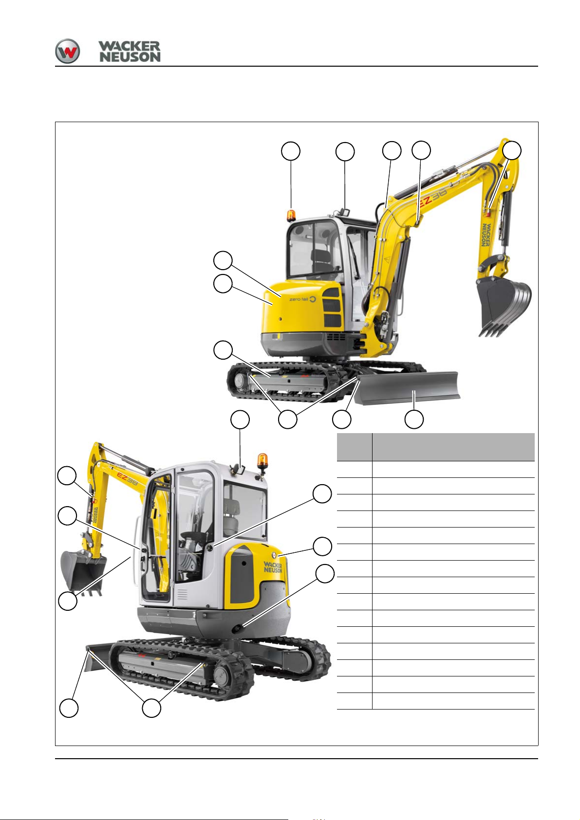
Fig. 3
Position
Designation
1 Working light on boom
2
Roof lights (option)
3
Lifting eye
4
Rotating beacon (option)
5
Door arrester
6
Engine cover
7
Fuel tank filler inlet
8
Exhaust pipe
9
Eye hook for tying down the machine
10
Stabilizer blade
11
Travel gear
12
Handle
13
Auxiliary hydraulics
14
Door handle and lock
15
Tank cover
1
6
3
3
8
2
3
4
9
9
10
11
12
13
15
5
14
13
2
7
Introduction
3Introduction
3.1 Machine overview
3
OM EZ38 us 1.1 * ez38e300.fm 3-1
Page 30

3
Information
Overview of models and trade names
Machine model/machine designation Trade name
E07-02 EZ38
3.2 Brief description of the machine
The machine model EZ38 is a self-propelled work machine.
Get informed on and follow the legal regulations of your country.
This machine is a versatile and powerful helper for moving earth, gravel
and debris on construction sites and elsewhere. A wide range of
attachments accounts for the numerous applications of the machine,
among others hammer and grab applications. During using these
attachments, observe the legal regulations of your country and equip the
machine with all the safety equipment required. See chapter 1.4 Fields of
application and use of attachments on page 3-5 for further applications.
The main components of the machine are:
• Travel gear
- Travel gear
- Stabilizer blade
- Live ring
• Upper carriage
- Cabin
- Water-cooled Diesel engine
- Hydraulic and electrical components
•Boom
The machine can be equipped with the “Telematic” option (for transmitting
operating data, location, etc. via satellite)!
The Diesel engine permanently drives a variable displacement pump
whose oil flow is sent to the control valve. Depending on actuation, the
pump supplies the hydraulic motors or the operating hydraulics with oil.
Schock cartridges for auxiliary hydraulics (option)
The auxiliary hydraulics are equipped with Schock cartridges to
compensate pressure peaks in the hydraulic system.
Zero tail
The upper carriage (without counterweight/option) does not protrude
beyond the width of the machine during rotation.
Cooling system
Coolant temperature is monitored with the indicator light on the machine’s
instrument panel.
3-2 OM EZ38 us 1.1 * ez38e300.fm
Page 31

Cabin/canopy
The cabin/canopy have been specially designed for protection in case of
an accident.
• ROPS/TOPS tested canopy (open version).
• ROPS/TOPS tested cabin (closed version/option).
• Protective FOPS structure (option) for cabin/canopy; protective
structure against falling objects.
• Front Guard (option) for cabin/canopy; protective structure against
objects from the front (pipes, tree trunks, for example).
• Shatter protection (option) for canopy; protective structure against
fragments flying around from the front.
Definition of FOPS/Front Guard categories
Level I:
Protection against small falling objects (FOPS) or small objects
penetrating into the cabin from the front (Front Guard), such as bricks,
small pieces of concrete, tools, for machines that are used for repairing
roads, landscaping work and for working on other construction sites, for
example.
3
Level II:
Protection against heavy falling objects (FOPS) or heavy objects
penetrating into the cabin from the front (Front Guard), such as trees,
pieces of rock, for machines that are used for clearance work, demolition
work and forestry work.
OM EZ38 us 1.1 * ez38e300.fm 3-3
Page 32

3
3.3 Notices and regulations on use
Designated use
• The machine is intended for:
- moving earth, gravel or rubble, for hammer operation as well as for
- working only with the attachments mentioned in chapter Fields of
application and use of attachments on page 3-5.
- Every other use is regarded as not designated for the use of the
machine. Wacker Neuson will not be liable for damage resulting from
use other than mentioned above. The operator/machine owner alone
will bear the risk.
Designated use also includes observing the instructions set forth in
the Operator’s Manual and observing the maintenance and service
conditions.
• The machine may not be used for transport jobs on public roads.
• In applications with lifting gear, the machine is used according to its
designated use only if the mandatory devices are installed and
functional.
• The quickhitch is only used for locking a matching attachment.
• A restricted work range applies to work with attachments (hammer, for
example) that can cause fragments to fly around.
3-4 OM EZ38 us 1.1 * ez38e300.fm
Page 33

Fields of application and use of attachments
NOTICE
Information
In order to avoid damage to the machine, only the attachments listed
below have been certified for installation on the machine.
► Contact a Wacker Neuson service center if you wish to use other
attachments.
Using attachments of other manufacturers, or attachments which have
been released for other machine types, can reduce the machine’s output
and stability considerably, and can also cause damage to the machine
and injuries to the operator or the personnel.
Compare the weight of the attachment and its maximum payload with the
indications in the lift capacity/stability table. Never exceed the maximum
payload stated in the lift capacity/stability table.
3
Please refer to the Operator’s and maintenance manual of the attachment
manufacturer for using and performing maintenance on attachments such
as hammers, grabs, hydraulic quickhitch, etc.
EZ38 without quickhitch
Bucket type Width Weight Capacity
Bucket 400 mm (16 in) 53 kg (117 lbs) 0.069 m
Bucket 600 mm (24 in) 70 kg (154 lbs) 0.107 m
Bucket 700 mm (28 in) 78 kg (172 lbs) 0.127 m
Ditch cleaning bucket 1000 mm (39 in) 87 kg (192 lbs) 0.117 m
Ditch cleaning bucket 1400 mm (55 in) 130 kg (287 lbs) 0.166 m
EZ38 with hydraulic Easy Lock quickhitch
Bucket type Width Weight Capacity
Bucket 300 mm (12 in) 56 kg (123 lbs) 0.051 m
Bucket 400 mm (16 in) 64 kg (141 lbs) 0.083 m
Bucket 500 mm (20 in) 75 kg (165 lbs) 0.086 m
Bucket 600 mm (24 in) 85 kg (187 lbs) 0.103 m
Bucket 700 mm (28 in) 92 kg (203 lbs) 0.120 m
Bucket 800 mm (31 in) 103 kg (227 lbs) 0.136 m
Ditch cleaning bucket 1000 mm (39 in) 92 kg (203 lbs) 0.113 m
Ditch cleaning bucket 1200 mm (47 in) 106 kg (234 lbs) 0.135 m
3
(2.44 ft3)
3
(3.8 ft3)
3
(4.5 ft3)
3
(4.1 ft3)
3
(5.9 ft3)
3
(1.8 ft3)
3
(2.9ft3)
3
(3.0 ft3)
3
(3.6 ft3)
3
(4.2 ft3)
3
(4.8 ft3)
3
(4.0 ft3)
3
(4.8 ft3)
OM EZ38 us 1.1 * ez38e300.fm 3-5
Page 34

3
EZ38 with hydraulic Easy Lock quickhitch
Bucket type Width Weight Capacity
Ditch cleaning bucket 1400 mm (55 in) 121 kg (267 lbs) 0.158 m3 (5.6 ft3)
Offset bucket 1200 mm (47 in) 142 kg (313 lbs) 0.129 m
Offset bucket 1400 mm (55 in) 153 kg (337 lbs) 0.150 m
EZ38 equipment
Attachments Weight
Hydraulic Easy Lock quickhitch console (HS 03) 33 kg (73 lbs)
Hammer bracket HS 03/NE 16 27 kg (60 lbs)
Hammer bracket HS 03/NE 22 30 kg (66 lbs)
Hammer NE 16 150 kg (331 lbs.)
Hammer NE 22 220 kg (485 lbs)
3
(4.6 ft3)
3
(5.3 ft3)
Hydraulic Easy Lock quickhitch console (HS 03) with Powertilt 104 kg (229 lbs)
3-6 OM EZ38 us 1.1 * ez38e300.fm
Page 35

tttt
WARNING
Fig. 4
Fig. 5
3.4 Labels
Type labels
3
Accident hazard! Replace missing or damaged labels immediately.
Can result in severe injury or death.
► Check warning and information labels regularly whether they are
missing or damaged.
► Never remove warning and information labels.
Serial number
The serial number is stamped on the machine chassis. It is also located
on the type label.
Type label
The type label is located at the front left on the upper carriage.
Description of attachment HYDRAULIC EXCAVATOR
Fahrzeug Seriennummer/serial no./no. de série Machine serial number
Fahrzeug Modell/model/modèle: Machine designation
Leistung/performance: Engine output
Typ/version: Machine type
Betriebsgewicht/operating weight/poids en
charge:
Transportgewicht/ transport weight/ poids en
transport:
G. Gew./GWR/PTAC:
Operating weight
Transport weight
Gross weight rating (admissible)
Max. Nutzlast/max. payload/max. charge utile: Maximum payload
Zul. Achslast vorne/front GAWR/PNBE AV:
Zul. Achslast hinten/rear GAWR/PNBE AR:
Front gross axle weight rating
Rear gross axle weight rat-
ing
EWG Nr./CEE no.: EEC check number
Baujahr/model year/année fabr.: Year of construction
OM EZ38 us 1.1 * ez38e300.fm 3-7
Page 36

3
Fig. 6
Fig. 7
Fig. 8
Fig. 9
Cabin number
The type label is located on the left C pillar.
Engine number
The type label is located on the cylinder-head cover (engine).
Hydraulic quickhitch
The serial number is located on the type label.
The type label is located on the hydraulic quickhitch fork.
Powertilt with hydraulic quickhitch
The serial number of the Powertilt is stamped in the housing near the
hydraulic connections.
The serial number of the hydraulic quickhitch is located on the type label.
The type label is located on the hydraulic quickhitch fork.
3-8 OM EZ38 us 1.1 * ez38e300.fm
Page 37

FOPS type label – large screen
Information
Fig. 10
Fig. 11
Fig. 12
The type label is located at the front in the middle of the chassis.
FOPS type label – small screen
The type label is located at the front left on the chassis.
3
Front Guard type label
The type label is located at the upper right of the chassis.
Type, quantity and position of the labels depend on options, country and
machine.
OM EZ38 us 1.1 * ez38e300.fm 3-9
Page 38

3
Fig. 13
Warning labels
3-10 OM EZ38 us 1.1 * ez38e300.fm
Page 39

Meaning
Fig. 14
Fig. 15
Fig. 16
Fig. 17
Fig. 18
Fig. 19
Crushing hazard.
All persons must stay clear of a raised load or of the danger zone.
Position
On the boom on the left and right.
Meaning
Potential high pressure grease discharge from the track tension
adjustment fitting.
Read the Operator’s Manual before working with the track tensioner.
Position
On the travel gear near the lubrication system.
Meaning
Crushing hazard.
Stay clear of the machine’s danger zone during operation.
3
Position
At the front of the chassis near the swiveling console.
Meaning
Explosion hazard.
Connecting jump leads incorrectly can cause explosions and personal
injuries with possible death.
Position
Next to the battery.
Meaning
Crushing hazard.
Stay clear of the machine’s swiveling range during operation.
Position
On the rear window.
Meaning
Modifications to the structure (welding, driling, for example), retrofitting
and incorrect repairs affect the protective effect of the cabin/canopy and
can cause serious injuries and even death.
Position
On the rear window.
OM EZ38 us 1.1 * ez38e300.fm 3-11
Page 40

3
Fig. 20
Fig. 21
Fig. 22
Fig. 23
Meaning
Crushing hazard.
1. Use the handholds for opening and closing the front window.
2. Lock the window into place.
Position
On the front window.
Meaning
Accumulator is under high pressure. Maintenance or repair work may only
be performed by a Wacker Neuson service center.
Position
In the engine compartment on the cover of the relay box.
Meaning (option)
This label indicates the emergency exit on machines equipped with the
Front Guard option.
Position
On the upper edge of the rear window in the cabin.
Meaning (option)
Crushing hazard.
Exceeding the specified load/stability can cause serious injuries and even
death.
Can cause serious damage to the machine.
Position
On the headliner.
3-12 OM EZ38 us 1.1 * ez38e300.fm
Page 41

Meaning
Fig. 24
Fig. 25
Read the Operator’s Manual before starting the machine.
Fasten the seat belt during operation.
Lower the boom and the stabilizer blade to the ground.
Remove the starting key and carry it with you.
Raise the control lever base.
Crushing hazard.
Serious damage to the machine.
Keep a safe distance from the boom.
Crushing hazard.
Serious damage to the machine.
During travel on slopes, pay attention to the maximum gradient angle and
maximum lateral angle of inclination.
Do not use high speed.
3
While operating the machine, maintain a safe distance from overhead
electric lines.
Can cause severe injuries due to electric shock.
Position
Canopy: on the C pillar on the left in driving direction.
Cabin: on the B pillar on the left in driving direction.
Meaning (option)
Always switch on the safe load indicator during lifting (gear) applications.
Failure to observe this can cause the machine to tip over, which in turn
can cause serious injuries and even death.
Read and understand the Operator’s Manual.
Position
On the B pillar on the left in traveling direction.
OM EZ38 us 1.1 * ez38e300.fm 3-13
Page 42

3
Fig. 26
Fig. 27
Fig. 28
Meaning
Read the Operator’s Manual before starting the machine.
Remove the starting key and carry it with you.
Injury hazard due to rotating parts.
• Open the engine cover only at engine standstill.
Burn hazard due to hot parts.
• Let the engine cool down.
Injury hazard due to fluid escaping under pressure.
• Let the engine cool down.
• Release the pressure in the hydraulic system and open the covers
carefully.
Position
On the engine cover.
Meaning
Burn hazard due to hot parts on the boom (lines, plug-and-socket
connections, threaded fittings, hydraulic cylinders, couplings, etc.).
Position
On the boom on the left and right.
Meaning
Reflector at the rear.
Position
On either side of the machine at the rear.
3-14 OM EZ38 us 1.1 * ez38e300.fm
Page 43

Labels
Fig. 29
3
OM EZ38 us 1.1 * ez38e300.fm 3-15
Page 44

3
Fig. 30
Fig. 31
1
2
3
Fig. 32
Fig. 33
Fig. 34
Meaning
Only refuel with Diesel fuel with a sulphur content of < 15 mg/kg (=
0.0015 %).
Position
Next to the fuel tank filler inlet.
Meaning (option)
The tank contains biodegradable hydraulic oil.
This label is notched on the side depending on the biodegradable
hydraulic oil used.
1. BP Biohyd SE-S 46
2. Panolin HLP Synth 46
3. Other biodegradable hydraulic oil
Position
Next to the filler inlet of the hydraulic oil reservoir.
Meaning
Indicates the lifting points of the machine.
Position
On either side of the stabilizer blade, and on either side of the boom.
Meaning
Indicates the tie-down points for tying down the machine.
Position
On either side of the stabilizer blade, and on either side of the travel gear
Meaning
Indication of sound power level produced by the machine.
L
= sound power level.
Wa
Position
At the front on the chassis.
3-16 OM EZ38 us 1.1 * ez38e300.fm
Page 45

Meaning
Fig. 35
Fig. 36
Fig. 37
Fig. 38
Indicates the interval at a which lubrication point must be lubricated.
Green grease nipples mean: lubrication every 50 hours or once a week.
Blue grease nipples mean: lubrication every 10 hours or daily.
Position
On the upper carriage at the front left in driving direction.
Meaning (option)
Indicates the lubrication points of the VDS tilt console.
Position
On the roof window on right-hand side in driving direction.
Meaning
This label indicates the position in which the control levers are locked.
Position
On the left-hand control lever base.
3
Meaning
Fuses.
Position
At the left under the seat.
OM EZ38 us 1.1 * ez38e300.fm 3-17
Page 46

3
Fig. 39
Fig. 40
Fig. 41
Meaning (option)
Check before starting the machine the operating pattern that has been
chosen. Label shows the lever position in which the ISO or SAE controls
are selected.
Wiring diagram Controls
A ISO controls Operating Pattern A
B SAE controls Operating Pattern B
Position
On the upper carriage at the front left in driving direction.
Meaning (option)
Indicates the control operations that do not comply with the ISO standard
if the SAE controls are selected.
Position
On the roof window on right-hand side in driving direction.
Meaning
The coolant must have a thermal stability of at least –30 °C (–22 °F).
Position
In the engine compartment on the expansion tank.
3-18 OM EZ38 us 1.1 * ez38e300.fm
Page 47

Meaning
Fig. 42
Fig. 43
Fig. 44
This label describes the functions of the pedals and control levers
(Operating Pattern A: ISO controls).
Check before starting the machine the operating pattern that has been
chosen.
Position
On the roof window on right-hand side in traveling direction.
Meaning
This label describes the functions of the pedals, control levers and of the
proportionally controlled auxiliary hydraulics (Operating Pattern A: ISO
controls).
Check before starting the machine the operating pattern that has been
chosen.
3
Position
On the roof window on right-hand side in traveling direction.
Meaning
This label describes the functions of the pedals, control levers and 3rd
control circuit/Powertilt with proportional controls (Operating Pattern A:
ISO controls).
Check before starting the machine the operating pattern that has been
chosen.
Position
On the roof window on right-hand side in traveling direction.
OM EZ38 us 1.1 * ez38e300.fm 3-19
Page 48

3
Fig. 45
Fig. 46
Fig. 47
Meaning
Indication of maintenance intervals.
Position
On the roof window on the left in traveling direction.
Meaning
This label describes the functions of the hydraulic Easy Lock quickhitch.
Position
On the roof window on right-hand side in traveling direction.
Meaning
This label shows how to refuel with a fuel-filling pump.
Position
Near the fuel-filling pump.
3-20 OM EZ38 us 1.1 * ez38e300.fm
Page 49

CAUTION
Information
Fig. 48
A
Fig. 49
A
Putting into operation
4 Putting into operation
4.1 Cabin/control stand
Safety instructions regarding entry and exit
Accident hazard! Risk of falling during entering or exiting.
Entering or exiting incorrectly can cause injuries.
► Keep the mandatory climbing aids A clean and use them for entering
and exiting.
► Face the machine as you enter and leave it.
► Have damaged climbing aids replaced.
Entry and exit (canopy)
Stop the machine (see chapter “Operation, stopping the machine”).
4
Cabin entry and exit (option)
Stop the machine (see chapter “Operation, stopping the machine”).
During entering or leaving the cabin, the door must be locked in the
arrester.
OM EZ38 us 1.1 * ez38i400.fm 4-1
Page 50

4
Fig. 50
A
R
Fig. 51
A
Locking and unlocking the door
Opening the door from the outside:
Press door lock A.
Locking the door:
1. Turn the key in door lock A clockwise (R).
2. The door is locked.
Unlocking the door:
1. Turn the key in door lock A counter-clockwise (L).
2. The door is unlocked.
Opening the door from the inside:
Press lever A on the door lock downward.
4-2 OM EZ38 us 1.1 * ez38i400.fm
Page 51

Securing an open door
Fig. 52
B
A
Fig. 53
A
Releasing the door arrester
4
Press bracket A against arrester B until it engages with an audible click.
Pull button A to release the door out of the arrester.
OM EZ38 us 1.1 * ez38i400.fm 4-3
Page 52

4
CAUTION
CAUTION
Fig. 54
Fig. 55
A
B
Opening/closing the front window
Crushing hazard due to unlocked cabin door!
Can cause minor injuries.
► Always lock the cabin doors.
► Use the handholds for closing the doors.
Crushing hazard! Be careful when opening and closing the front
window.
Can cause minor injuries.
► Hold both handles.
► Duck your head.
► Let both locks lock into place.
► Keep extremities and clothing clear of the window channel.
Opening the front window
1. Keep levers A pressed on the left and right, and pull the front window
upward with both handles B.
4-4 OM EZ38 us 1.1 * ez38i400.fm
Page 53

2. Release levers A and let them engage in both locks C.
Fig. 56
C
A
Fig. 57
A
B
Fig. 58
A
Closing the front window
1. Press levers A on the left and right, and pull the front window
downward with both handles B.
4
2. Press levers A on either side and engage them in the lock.
OM EZ38 us 1.1 * ez38i400.fm 4-5
Page 54

4
Fig. 59
Fig. 60
B
C
A
Fig. 61
A
B
C
Opening the lower front window
1. Press levers A on the left and right, and pull the front window upward
with both handles B.
2. Let levers A engage in both locks C.
Closing the lower front window
1. Keep levers A pressed on the left and right, and pull the lower front
window downward with handles B.
2. Release levers A and let them engage in both locks C.
4-6 OM EZ38 us 1.1 * ez38i400.fm
Page 55

Opening the whole front window
Fig. 62
Fig. 63
A
B
C
Fig. 64
A
B
Fig. 65
A
C
1. Press levers A on the left and right, and pull the lower front window
upward with both handles B.
2. Let levers A engage in both locks C.
4
3. Keep levers A pressed on the left and right, and pull the entire front
window upward with both handles B.
4. Release levers A and let them engage in both locks C.
OM EZ38 us 1.1 * ez38i400.fm 4-7
Page 56
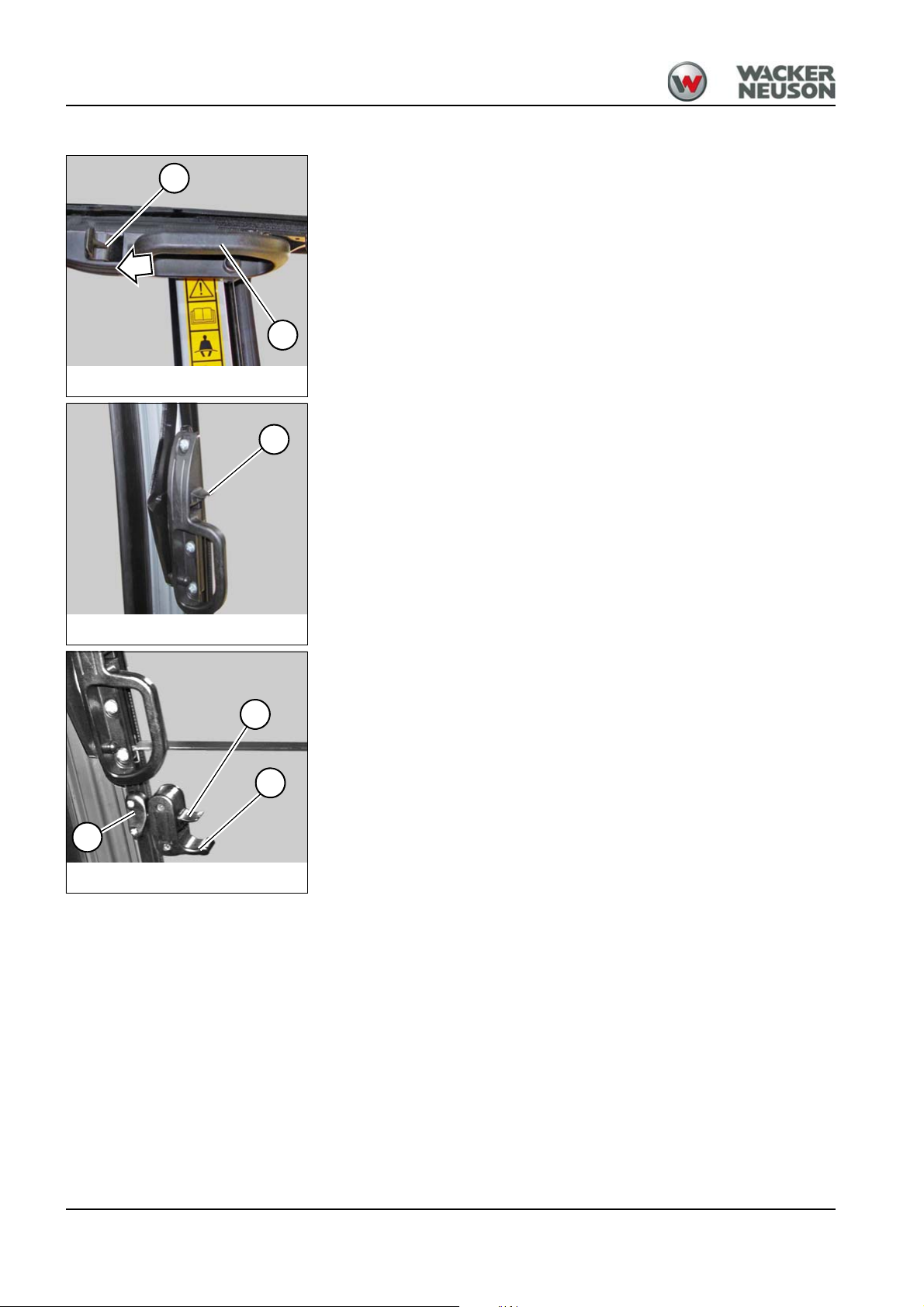
4
Fig. 66
B
A
Fig. 67
A
Fig. 68
A
B
C
Closing the whole front window
1. Press levers A on the left and right, and pull the front window
downward with both handles B.
2. Press levers B and make them lock into place on either side.
3. Keep levers A pressed on the left and right, and pull the lower front
window downward with handles B.
4. Release levers A and let them engage in both locks C.
4-8 OM EZ38 us 1.1 * ez38i400.fm
Page 57

Opening the front window to a gap (ventilation position)
Fig. 69
Fig. 70
B
A
Fig. 71
D
Open
1. Press levers A on either side and pull the front window to the inside.
2. Release levers A and let them engage in both locks B.
Close
1. Press levers A on either side.
2. Press the front window forward and let it engage.
4
Opening/closing the side window
Open
Press lever D upward and let the side window engage in the required
recess.
Close
Press lever D upward and close.
OM EZ38 us 1.1 * ez38i400.fm 4-9
Page 58

4
WARNING
WARNING
CAUTION
Fig. 72
A
Emergency exit
Personal injury hazard during emergency exit!
Can cause severe injury or death.
► The emergency exits through the front and right windows of the
machine have neither footholds nor handholds for safely entering or
exiting the cabin.
The front or right window can be used for exiting the cabin in an
emergency.
Emergency exit on machines equipped with protective Front Guard structures
(option)
Personal injury hazard during emergency exit using the right
window!
Can cause severe injury or death.
► The emergency exit through the right window of the machine has
neither footholds nor handholds for safely entering or exiting the cabin.
Personal injury hazard due to glass splinters!
Can cause minor injuries.
► Protect your face and eyes from the glass splinters flying around.
The rear or right window can be used as an emergency exit if the door is
blocked.
The rear window is broken with emergency hammer A fastened over the
rear window.
4-10 OM EZ38 us 1.1 * ez38i400.fm
Page 59

Seat adjustment
WARNING
CAUTION
Fig. 73
70 kg
A
Fig. 74
B
4
Accident hazard due to distraction when adjusting the seat!
Adjusting the seat during machine operation can cause severe injury or
death.
► Adjust the seat before putting the machine into operation.
► Ensure that the levers for seat adjustment are locked into place.
Weight adjustment
Injury hazard due to incorrect seat adjustment!
An incorrect weight adjustment can cause injuries to the spinal cord.
► Ensure that the seat is correctly adjusted to the operator’s weight
before traveling or operating the machine.
1. Sit down on the seat.
2. Turn lever A counter-clockwise.
➥ Adjusts a higher weight.
3. Turn lever A clockwise.
➥ Adjusts a lower weight.
Backrest adjustment
1. Sit down on the seat.
2. Pull lever B upward and lean back at the same time to push the
backrest into the required position.
3. Let lever B lock into place.
OM EZ38 us 1.1 * ez38i400.fm 4-11
Page 60

4
Fig. 75
C
Horizontal adjustment
1. Sit down on the seat.
2. Pull lever C upward and move the seat forward or backward at the
same time.
4-12 OM EZ38 us 1.1 * ez38i400.fm
Page 61

Seat belt adjustment
DANGER
WARNING
WARNING
4
Personal injury hazard! Do not travel or operate with the seat belt
unbuckled!
Will cause serious injuries or death.
► Fasten and adjust your seat belt before traveling or operating the
machine.
► Do not twist the seat belt when you fasten it.
► Firmly fasten your seat belt over your hips and not over your stomach.
► Do not place the seat belt over hard, edged or fragile items (tools, for
example).
Injury hazard due to damaged or dirty seat belt!
A damaged or dirty seat belt can cause serious injuries or death.
► Keep the seat belt and buckle clean, and check them for damage.
► Have a damaged seat belt and buckle immediately replaced by a
Wacker Neuson service center.
► Have the seat belt immediately replaced after every accident and the
bearing capacity of the fastening points and seat fixtures checked by a
Wacker Neuson service center.
Accident hazard! Do not adjust the seat belt during machine
operation!
Adjusting the seat belt during machine operation can cause serious
injuries or death.
► Adjust the seat belt before machine operation.
► Ensure that the buckle is inserted (pull test).
OM EZ38 us 1.1 * ez38i400.fm 4-13
Page 62

4
Fig. 76
A
B
C
Fig. 77
C
B
D
Fig. 78
A
Fastening the seat belt
1. Insert buckle latch A into seat belt buckle B with an audible click.
2. Tighten seat belt C by pulling at its end.
Unfastening the seat belt
1. Press the red pushbutton switch D on seat belt buckle B until the
buckle latch comes out.
2. Place seat belt C aside.
Longer/shorter seat belt adjustment
Longer seat belt adjustment
Hold buckle latch A at a right angle to the seat belt and pull the seat belt to
the required length.
Shorter seat belt adjustment
Pull the free end of the seat belt and shorten it to the required length.
4-14 OM EZ38 us 1.1 * ez38i400.fm
Page 63

Adjusting the retracting seat belt (option)
DANGER
WARNING
WARNING
Personal injury hazard! Do not travel or operate with the seat belt
unbuckled!
Will cause serious injuries or death.
► Fasten and adjust your seat belt before traveling or operating the
machine.
► Do not twist the seat belt when you fasten it.
► Firmly fasten your seat belt over your hips and not over your stomach.
► Do not place the seat belt over hard, edged or fragile items (tools, for
example).
Injury hazard due to damaged or dirty seat belt!
A damaged or dirty seat belt can cause serious injuries or death.
► Keep the seat belt and buckle clean, and check them for damage.
► Have a damaged seat belt and buckle immediately replaced by a
Wacker Neuson service center.
► Have the seat belt immediately replaced after every accident and the
bearing capacity of the fastening points and seat fixtures checked by a
Wacker Neuson service center.
4
Accident hazard! Do not adjust the seat belt during machine
operation!
Adjusting the seat belt during machine operation can cause serious
injuries or death.
► Adjust the seat belt before machine operation.
► Ensure that the buckle is inserted (pull test).
OM EZ38 us 1.1 * ez38i400.fm 4-15
Page 64

4
Fig. 79
A
B
Fig. 80
D
B
C
Fastening the retracting seat belt
Insert buckle latch A into seat belt buckle B with an audible click.
Unfastening the retracting seat belt
1. Press the red pushbutton switch D on seat belt buckle B until the
buckle latch comes out.
Seat belt C is automatically retracted.
4-16 OM EZ38 us 1.1 * ez38i400.fm
Page 65

Adjusting the rearview mirrors (option)
WARNING
WARNING
WARNING
Accident hazard due to persons in the danger zone!
Persons in the danger zone are possibly not seen and can be injuried
while reversing the machine.
► Adjust the existing visual aids (rearview mirrors, for example) correctly.
► Stop work immediately if persons enter the danger zone.
► Pay attention to the movements and changing positions of attachments
and persons.
Accident hazard due to restricted field of vision on the job site!
Accidents resulting in severe injuries or death can be caused by a
restricted field of vision.
► Ensure that no one is in the danger zone.
► Use suitable visual aids if necessary (camera, mirrors, guide, for
example).
► Additional equipment or attachments must not be installed if they
impair visibility.
4
Accident hazard due to incorrect adjustment of visual aids!
Incorrectly adjusted visual aids can cause serious injuries or death.
► Adjust the visual aids before machine operation.
► Immediately replace damaged or broken visual aids.
► Curved mirrors enlarge, reduce or distort the field of view. Bear this in
mind during adjusting and using such mirrors.
Before using the machine, before starting work or when changing
operators, ensure that all visual aids (mirrors, for example) work correctly,
that they are clean and adjusted in accordance with the instructions in this
Operator’s Manual. The operator must observe the local regulations.
• Use safety-oriented ladders and work platforms for adjustment work on
the machine.
• Never use machine parts or attachments/superstructures as a climbing
aid.
OM EZ38 us 1.1 * ez38i400.fm 4-17
Page 66

4
Information
Information
Information
Fig. 81
Adjusting the mirrors
Adjust the mirrors in order to:
• Ensure sufficient visibility from the seat onto the travel area and job
site.
• Ensure maximum visibility to the rear.
• Ensure visibility of the rear left edge of the machine in the left-hand
mirror.
• Ensure visibility of the rear right edge of the machine in the right-hand
mirror.
Set the machine to travel position before adjusting the mirrors –
see “Travel position” on page 5-3.
We recommend having the mirrors adjusted by a second person.
Do not make any changes or modifications that impair visibility. Otherwise
the machine does not meet the requirements for conformity and licensing.
4-18 OM EZ38 us 1.1 * ez38i400.fm
Page 67

Control lever base
Fig. 82
4
4
Raise the control lever base 4 after stopping the engine.
Control lever base raised:
• All hydraulic functions are locked.
• The upper carriage is secured against rotation. (The swivel unit brake
is enabled.)
• The engine will not start unless the control lever base is raised.
Control lever base lowered:
• All hydraulic functions are active.
• The upper carriage can be rotated.
• The engine cannot be started.
Functional check of control lever base
Perform a functional check of the control lever base every time before you
start the machine.
1. Start the machine.
2. Fold the control lever base down.
3. Travel on open terrain.
4. Secure the danger zone.
5. Stop the machine.
6. Raise the control lever base.
7. Move all control levers and pedals in all directions.
➥ The selected elements must not move.
➥ Work may be performed with the machine.
8. The selected elements move:
➥ Stop operation immediately.
➥ Contact a Wacker Neuson service center and have the malfunction
rectified.
OM EZ38 us 1.1 * ez38i400.fm 4-19
Page 68

4
Information
Fig. 83
A
Fig. 84
Armrest
Fire extinguisher
1. Hold the armrest, and loosen and pull out button A.
2. Move the armrest to the required position.
3. Let button A lock into place and tighten it.
A fire extinguisher is not available, neither as standard nor optional
equipment.
If necessary, a fire extinguisher according to NFPA must be installed by a
Wacker Neuson service center.
A suitable bracket for the cabin or canopy must be fastened on the cabin
framework behind the seat.
Ensure the firm and safe mounting of the fire extinguisher. Check the fire
extinguisher at regular intervals, also ensure that it is safely installed.
Observe the manufacturer’s indications.
4-20 OM EZ38 us 1.1 * ez38i400.fm
Page 69

Protective structures
DANGER
Information
4
Protective structures are additional elements that protect the operator
against danger. These elements can be installed later on or as standard
equipment.
Accident due to modified cabin or protective structures!
Modifications (drilling, for example) weaken the structure and will cause
serious injuries or death.
► No drilling, cutting or grinding.
► Do not install any brackets.
► No welding, straightening or bending.
► Replace the complete protective structure if it is damaged, deformed
and/or cracked.
► Contact a Wacker Neuson service center in case of doubt.
► Retrofit, assembly and repair work may only be performed by a
Wacker Neuson service center.
► Replace self-locking fasteners.
Machine operation is only allowed with a correctly installed and intact
cabin or correctly installed and intact canopy.
For additional protection, only use correctly installed and intact Wacker
Neuson protective structures that have been released for the machine.
Responsibility for machine equipped with protective structures
The decision regarding the necessary protective structures (type and level
I or II) must be made by the machine owner and depends on the specific
work situation.
The machine owner must observe the national regulations and he must
inform the operator on the protective structure to be used in a specific
work situation.
OM EZ38 us 1.1 * ez38i400.fm 4-21
Page 70

4
DANGER
Information
Protective FOPS structure/small screen – level I (option)
Crushing hazard! Falling objects.
Will cause severe injury or death.
► Install a protective FOPS structure in areas with risk of falling objects.
► Machine operation is prohibited without a protective FOPS structure.
The protective FOPS structure corresponds to level I according to ISO
3449:1992
► The machine owner must ensure that the hazard situation is evaluated
and that the national regulations are observed.
► The machine owner must ensure that only work is performed that does
not require any higher protection.
► Accidents cannot be fully avoided despite equipping a machine with
protective structures.
4-22 OM EZ38 us 1.1 * ez38i400.fm
Page 71

Installing
Fig. 85
Fig. 86
B
A
Fig. 87
C D
1. Stop and park the machine. Stop the engine. See “Preparing
lubrication”.
2. Remove all lights and mirrors (option).
3. A minimum 2 persons are required for installing/removing.
4. Install the lock nuts and screws on either side.
5. Tighten screws A (M10) and lock nuts on the left and right to 45 Nm
(33 ft.lbs).
6. Tighten screws B (M12) and lock nuts on the left and right to 87 Nm
(64 ft.lbs).
4
7. Install the light in position C (option).
8. Install the mirror in positions D (option).
OM EZ38 us 1.1 * ez38i400.fm 4-23
Page 72

4
DANGER
Information
Protective FOPS structure/large screen – level I (option)
Crushing hazard! Falling objects.
Will cause severe injury or death.
► Install a protective FOPS structure in areas with risk of falling objects.
► Machine operation is prohibited without a protective FOPS structure.
The protective FOPS structure corresponds to level I according to ISO
3449:2008.
► The machine owner must ensure that the hazard situation is evaluated
and that the national regulations are observed.
► The machine owner must ensure that only work is performed that does
not require any higher protection.
► Accidents cannot be fully avoided despite equipping a machine with
protective structures.
4-24 OM EZ38 us 1.1 * ez38i400.fm
Page 73

Installing
Fig. 88
Fig. 89
A
B
Fig. 90
C
C
1. Stop and park the machine. Stop the engine. See “Preparing
lubrication”.
2. Remove all lights (option).
3. A minimum 2 persons are required for installing/removing.
4. Install the lock nuts and screws on either side.
5. Mounting point for protective structure: A.
6. Tighten screws B and lock nuts on the left and right to 65 Nm (48
ft.lbs.).
4
7. Mounting point for cabin/canopy: C
OM EZ38 us 1.1 * ez38i400.fm 4-25
Page 74

4
DANGER
Information
Fig. 91
Fig. 92
A
Protective Front Guard structure level I (option)
Crushing hazard by objects from the front!
Will cause severe injury or death.
► Install a protective Front Guard structure in areas with hazard from the
front, for example pipes, tree trunks etc.
► Machine operation is prohibited without a protective Front Guard
structure.
The protective Front Guard structure corresponds to level I according to
ISO 10262:1998.
► The machine owner must ensure that the hazard situation is evaluated
and that the national regulations are observed.
► The machine owner must ensure that only work is performed that does
not require any higher protection.
► Accidents cannot be fully avoided despite equipping a machine with
protective structures.
Installing
1. Stop and park the machine. Stop the engine. See “Preparing
lubrication”.
2. Remove all lights and mirrors (option).
3. A minimum 2 persons are required for installing/removing.
4. Install the lock nuts and screws on either side.
5. Mounting point for protective structure: A (upper).
4-26 OM EZ38 us 1.1 * ez38i400.fm
Page 75

6. Mounting point for protective structure: B (lower).
Fig. 93
B
Fig. 94
C
D
Fig. 95
F
E
G
Fig. 96
E
7. Mounting point for cabin/canopy: C (upper)/D (lower).
4
8. Tighten lock nuts and screws E to 65 Nm (48 ft.lbs.).
9. Install the mirror in both positions F (option).
10.Install the light in position G (option).
OM EZ38 us 1.1 * ez38i400.fm 4-27
Page 76

4
DANGER
CAUTION
NOTICE
Information
Shatter protection (option)
Piercing/penetration hazard by objects from the front!
Work involving piercing/penetrating objects from the front will cause
accidents with serious injuries or death.
► If the machine is equipped with a canopy, a shatter protection must be
installed if an attachment (a hammer, for example) causes fragments
to fly around. This shatter protection takes over the function of a front
window. If the machine is equipped with a cabin, the front window must
be closed during hammer operation.
► Pay attention to the restricted work range (see fig. 97/98).
► Canopy operation is prohibited without a shatter protection.
Accident hazard in conditions of restricted visibility due to rain,
snowfall, dust etc.!
Restricted visibility can cause minor injuries.
► Stop machine operation immediately.
► Resume work only if visibility is no longer restricted.
Do not use brushes, steel wool or other abrasive cleaners for cleaning the
polycarbonate disc. Do not wipe dust in a dry state.
The shatter protection (canopy option) protects the operator against
fragments from the front.
► The machine owner must ensure that the hazard situation is evaluated
and that the national regulations are observed.
► The machine owner must ensure that only work is performed that does
not require any higher protection.
► Accidents cannot be fully avoided despite equipping a machine with
protective structures.
The shatter protection can be combined with a protective Front Guard
structure if the machine is equipped with a canopy.
4-28 OM EZ38 us 1.1 * ez38i400.fm
Page 77

Job site
Information
Fig. 97
A
Fig. 98
Fig. 99
B
B
A
Fig. 100
C
Height of job site A: 120 cm (47 in).
Figures 97 and 98 refer to work with a Wacker Neuson hydraulic hammer.
Working with another attachment can modify the height of the job site.
4
Installing
1. A minimum 2 persons are required for installing/removing.
2. Stop and park the machine. Stop the engine. See “Preparing
lubrication”.
3. Install/remove shatter protection A from the front and fasten/remove it
at the fastening points B with the fastening material supplied.
4. Tighten screws C at fastening points B to 25 Nm (18 ft.lbs).
OM EZ38 us 1.1 * ez38i400.fm 4-29
Page 78

4
Fig. 101
A
Fig. 102
B
C
Fig. 103
D E
Fig. 104
F
Checking the screw connections of the cabin
1. Raise the floor mat on the outer left side.
2. Tighten screw A to 85 Nm (63 ft.lbs).
3. Raise the floor mat on the outer right side.
4. Tighten lock nut B to 85 Nm (63 ft.lbs).
5. Tighten screw C to 85 Nm (63 ft.lbs).
6. Tighten screw D to 85 Nm (63 ft.lbs).
7. Tighten screw E to 85 Nm (63 ft.lbs).
8. Tighten screw F to 85 Nm (63 ft.lbs).
4-30 OM EZ38 us 1.1 * ez38i400.fm
Page 79

Document box (option)
Fig. 105
A document box on the headliner is available as an option for the cabin.
Socket
A 12 V socket is located at the front left of the machine chassis.
4.2 Overview of control elements
This chapter describes the controls, and contains information on the
function and handling of the indicator lights and controls in the cabin.
The pages stated in the table refer to the description of the controls.
4
OM EZ38 us 1.1 * ez38i400.fm 4-31
Page 80

4
2
1
3
6
12
23
8
9
10
15
17
14
19
18
21
4
6
5
22
13
Fig. 106Overview of control elements – proportional controls
Fig. 106 Overview of control elements
16
20
11
7
21
Cabin
4-32 OM EZ38 us 1.1 * ez38i400.fm
Page 81

Designation See page
1 Travel pedals/travel levers
2 Boom swivel/auxiliary hydraulics pedal (AUX I)
3 Foot-operated pushbutton switch for hydraulic quickhitch (option)
4 Control lever base
5Horn
6 Control levers
7 Travel speed changeover
8 Stabilizer-blade lever
9 Display element
10 Oil flow AUX I rotary switch (proportional controls)
11 Starter lock
12 Right-hand switch panel
13 12 V power outlet (cabin option)
14 Temperature controller (cabin option)
15 Radio (option)
16 ISO/SAE changeover
17 Seat
18 Throttle
19 Oil flow AUX II rotary switch (proportional controls)
20 Switch panel on left-hand control lever base
21 Changeover of boom swivel pedal
22 Powertilt (AUX II) or 3rd control circuit (AUX II) operation (proportional controls option)
23 Boom swivel, auxiliary hydraulics (AUX I) operation (proportional controls option)
5-15
5-26, 5-25
5-32
4-19
5-9
5-13
5-1
5-20
4-36
5-21
4-43
4-34
--
5-11
--
5-19
4-11
5-1
5-21
4-34
--
5-30, 5-29
5-26, 5-25
24 Boom swivel pedal (proportional controls option)
4
OM EZ38 us 1.1 * ez38i400.fm 4-33
Page 82

4
Fig. 107
Switch panel on left-hand control lever base
Right switch panel (cabin)
26
27
25
28 29
30
31
32
3435
39 40 41 42
43
33
36
48 49 50
44
45
46
47
44
47
Right switch panel (canopy)
38
36
37
Display element and switches
4-34 OM EZ38 us 1.1 * ez38i400.fm
Page 83

Designation See page
25 High speed (2nd speed)
26 Fuel level indicator
27 Coolant temperature
28 Charge indicator light
29 Engine oil pressure
30 Preheating
31 Safe load indicator light
32 Coolant temperature
33 For Wacker Neuson service center
34 Hour meter/maintenance meter
35 Hour meter/maintenance meter changeover
36 Not assigned
37 Hydraulic oil filter monitoring
38 Air filter monitoring
39 Tilting the upper carriage (Vertical Digging System) (option)
40 Working lights
41 Safe load indicator (option)
42 Hydraulic quickhitch (option)
43 Wiper/wash system (cabin)
44 Rotating beacon (option)
45 Ventilation/heating (cabin)
46 Air conditioning
47 Automatic engine speed setting (option Tier IV interim)
48 Maintenance meter
49 Service hours
50 Hours
5-1
4-37
4-37
4-36
4-36
4-36
4-36
4-37
--
4-38
4-37
--
4-37
4-37
5-54
5-8
5-48
5-32
5-10
5-9
5-11
5-12
5-2
4-38
4-38
--
4
OM EZ38 us 1.1 * ez38i400.fm 4-35
Page 84

4
Information
4.3 Indicator lights and warning lights (overview)
Display element
The display element provides information on the operating state.
and defects.
After switching on starter, the indicator lights are checked during the first 2
seconds. During this time the current reading of the maintenance meter is
displayed. Then the service hours are automatically displayed.
Symbol Designation
High speed (2nd speed)
The indicator light (green) illuminates if high speed is enabled.
Charge indicator light
This indicator light (red) illuminates if the electrical system has a malfunction. The battery is no longer or insufficiently charged.
Note: This indicator light also illuminates if the starting key is turned to
position 2. The indicator light goes out after the engine is started.
Increase engine speed if the indicator light illuminates. The electrical
system works if the indicator light of the electrical system goes out within
one minute.
Engine oil pressure
The indicator light (red) illuminates and the buzzer sounds.
• Stop the engine immediately and check the oil level.
• If the engine oil level is correct, contact a Wacker Neuson service
center.
Note: The indicator light illuminates when the starter is turned on and
goes out as soon as the engine runs.
At low temperatures, the indicator light can illuminate a few seconds after
the engine is started.
Preheating
The indicator light (yellow) illuminates if the starting key is in position 2.
The indicator light goes out after 4 seconds and the engine can be
started. (Air is preheated.)
Contact a Wacker Neuson service center if the indicator light does not go
out.
Safe load indicator light
The safe load indicator gives the operator optical (red) and acoustic
warnings when the values of the stability table are reached or exceeded.
• Reduce reach or the lift load until both the acoustic signal and the
indicator light in the display element go out.
4-36 OM EZ38 us 1.1 * ez38i400.fm
Page 85
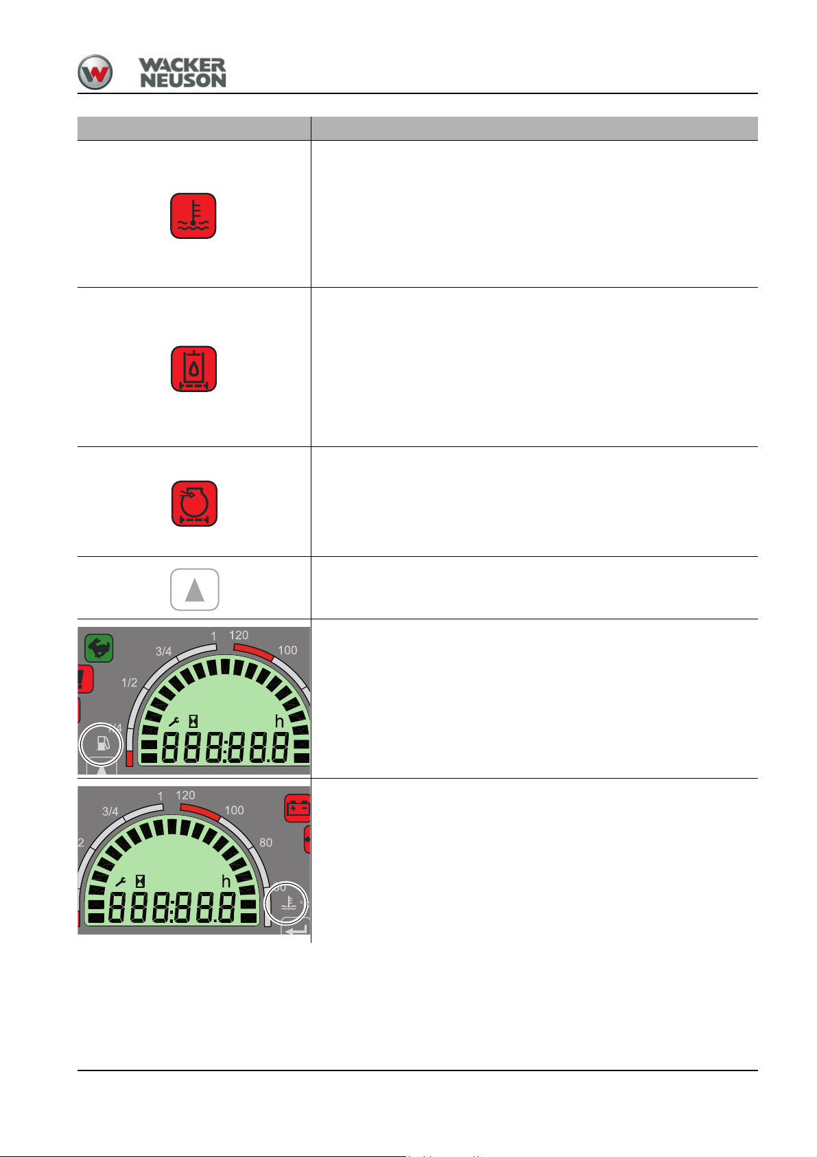
Symbol Designation
Coolant temperature
If the coolant temperature segment reaches the red range, the indicator
light (red) illuminates and the buzzer sounds.
• Let the engine run at idling speed without any load.
• Wait until the temperature drops and the indicator light goes out.
• Stop the engine.
• Check the coolant level.
Hydraulic oil filter monitoring
The indicator light (red) illuminates if the hydraulic oil filter has to be
replaced.
In cold weather the indicator light can illuminate immediately when the
engine is started. Warm up the machine at low engine speed and little
load.
Contact a Wacker Neuson service center if the indicator light does not go
out.
Air filter monitoring
The indicator light (red) illuminates if the air filter is dirty and if it has to be
replaced.
• Stop and park the machine.
• Contact a Wacker Neuson service center.
4
Changeover between hour meter and maintenance counter
Fuel level indicator
Indicates the remaining amount of fuel in the tank.
Refuel if the segments reach the red range.
Coolant temperature
Indicates the current coolant temperature of the engine.
The indicator light illuminates if the segments reach the red range.
• Let the engine run at idling speed without any load.
• Wait until the temperature drops and the indicator light goes out.
• Stop the engine.
• Check the coolant level.
OM EZ38 us 1.1 * ez38i400.fm 4-37
Page 86

4
Symbol Designation
Hour meter/maintenance meter
Counts the engine service hours with the engine running.
Hour meter
The counter runs as soon as the charge indicator light goes out. The
hour meter is used for specifying the maintenance intervals.
Maintenance meter (service hours up to next servicing)
The maintenance meter starts at 500.0 hours. It counts down to 0.0
hours. A wrench symbol flashes as soon as the maintenance meter
reaches this value. The meter keeps on counting down (−0.1 hours,
−0.2 hours, etc.).
4-38 OM EZ38 us 1.1 * ez38i400.fm
Page 87

4.4 Preparatory work
Information before putting the machine into operation
Before putting the machine into operation, perform a visual check to
ensure that:
- there are no leaks,
- no parts are damaged or loose,
- there are neither persons nor objects,
- or other sources of danger around the machine.
Before putting the machine into operation, the operator must familiarize
himself with the position of the controls and instruments.
The machine may only be operated from the seat and with the seat belt
fastened.
Before the operator uses the machine in work operation for the first time,
we recommend first trying out the machine on open ground without any
obstacles.
During using the machine, check the surroundings constantly in order to
identify potential hazards in time.
Before using the machine, before starting work or when changing
operators, ensure that all visual aids (mirrors, for example) work correctly,
that they are clean and adjusted in accordance with the instructions in this
Operator’s Manual. The machine owner must observe the local
regulations.
Perform a functional check of the control lever base.
Perform a functional check of the safe load indicator (option).
Do not make any changes or modifications that impair visibility. Otherwise
the machine does not meet the requirements for conformity and licensing.
Observe the safety instructions in chapter Safety 2.4.
4
Requirements and notices for the operating personnel
Read, understand and follow this Operator’s Manual and all other
Operator’s Manuals supplied with the machine.
The machine may only be put into service by a qualified technician that
has been instructed. See chapter “Safety 2.3”.
The operator must know and bear in mind the requirements and risks at
the job site.
Perform daily maintenance according to the Lubrication and maintenance
plan (see chapter “Maintenance 7.2”)
Face the machine as you enter and leave it.
Keep the footholds and the handles clean to ensure a safe hold at all
times. Immediately remove dirt, for example oil, grease, dirt, snow or ice.
Always use the mandatory climbing aids during entering and exiting the
machine.
Never get on a moving machine and never jump off the machine.
OM EZ38 us 1.1 * ez38i400.fm 4-39
Page 88

4
Check lists
The checklists below are intended to assist you in checking and
monitoring the machine before, during and after operation. These
checklists cannot claim to be exhaustive.
If the answer to one of the following questions is No, first rectify the cause
of the fault (or have it rectified) before starting or continuing work.
The checking and monitoring work listed below is described in greater
detail in the following chapters.
Start-up checklist
Check and observe the following points before putting the machine into
operation or starting the engine:
No. Question Page ✔
Enough fuel in the tank? 7-27
1
Water in water separator and fuel filter checked and
2
drained if necessary?
Correct engine oil level? 7-33
3
Coolant level OK? 7-35
4
Correct oil level in the hydraulic oil reservoir? 7-43
5
Glass cleaner in washer tank OK? 7-49
6
Lubrication points greased? 7-6
7
Tracks checked for cracks, cuts etc.? --
8
Light system, signalling, warning and indicator lights
9
operational?
Windows, mirrors, lights, steps, all pedals and control
10
levers clean?
7-31
7-32
--
--
All control levers and pedals in neutral position? --
11
Control lever base raised? 4-19
12
Attachment safely locked?
13
Engine cover locked?
Filler cap closed tightly?
14
Tank cover firmly screwed?
Especially after cleaning, maintenance or repair
15
work: Rags, tools and other loose objects removed?
Seating position adjusted correctly? 4-11
16
Are all mirrors functional and adjusted correctly? 4-17
17
Seat belt fastened? 4-13
18
Before putting the machine into operation, ensure
19
that no one is in the danger zone.
5-32
5-41
7-14
--
--
4-40 OM EZ38 us 1.1 * ez38i400.fm
Page 89

Operation checklist
After starting the engine and during operation, check and observe the
following points:
No. Question Page ✔
Anyone in the danger zone of the machine? --
1
Indicator light for engine oil pressure and alternator
2
charge function gone out?
Coolant temperature of engine in normal range? 4-37
3
Indicator lights for hydraulic oil filter and air filter do
4
not illuminate?
Do the pedals and control levers work correctly? 5-13
5
Performed functional check of control lever base? 4-19
6
4-36
4-37
Parking checklist
Check and observe the following points during parking the machine:
No. Question Page ✔
Attachment lowered to the ground?
1
Stabilizer blade lowered to the ground? 5-20
2
Control lever base raised? 4-19
3
Cabin locked, especially if the machine cannot be
4
supervised?
5-34
5-39
4-2
4
When parking on public roads:
Machine adequately secured?
Machine additionally secured with chocks under the
5
tracks to prevent it from rolling away?
When parking on slopes:
Machine additionally secured with chocks under the
6
tracks to prevent it from rolling away?
5-7
5-7
OM EZ38 us 1.1 * ez38i400.fm 4-41
Page 90

4
Information
Putting the machine into operation for the first time and running-in period
Before putting the machine into operation for the first time, check it
visually for exterior damage due to transport, and check whether the
equipment supplied with the machine is complete.
• Check the fluid levels according to chapter “Maintenance”.
Each machine is correctly adjusted and checked before it is delivered.
Handle the machine carefully during its first 50 operating hours.
• Do not load a cold engine.
• Warm up the machine at low engine speed and little load, do not warm
it up at a standstill.
• Do not change engine speed abruptly.
• Avoid using the machine under heavy loads and/or at high speeds.
• Avoid abrupt acceleration, braking and changing traveling direction.
• Do not run the engine at high speed for extended periods.
• Strictly observe the maintenance plans and perform (or have
performed) the mandatory maintenance on or with the machine –
see chapter “7.2 Maintenance overview” on page 7-2.
traveling on public roads
The machine is not certified for travel on public roads.
4-42 OM EZ38 us 1.1 * ez38i400.fm
Page 91

4.5 Starting and stopping the engine
WARNING
Information
Information
Fig. 108
0
1
2
3
P
Preparations for starting the engine
Accident hazard due to uncontrollable machine operation!
Uncontrollable operation can cause serious injuries or death.
► Only operate the machine from the seat with the seat belt fastened.
Set the throttle to the medium position if the engine is cold.
The starter cannot be actuated if the engine is already running (start
repeat interlock).
Do not run the starter for more than 10 seconds.
Wait about 1 minute so the battery can recover and the starter does not
overheat before trying again.
4
Starter lock
Ensure that there is sufficient ventilation before operating the machine in
enclosed areas.
All controls must be within easy reach. You must be able to move the
travel levers to their limit positions.
Position Function
P Park position Not assigned
0 Stop position Insert or remove the starting key
1 Travel position All electric functions are enabled
2 Preheats the engine Preheater active
3 Starts the engine Starter is actuated
OM EZ38 us 1.1 * ez38i400.fm 4-43
Page 92

4
NOTICE
NOTICE
Information
Fig. 109
0
1
2
3
P
Fig. 110
30 3129
Starting the engine
In order to avoid damage to the starter.
► Wait at least 10 seconds before starting the engine again.
Damage to preheater if the preheating system is operated too long.
► Never preheat the engine more than 3 – 5 seconds.
1. Insert the starting key.
2. Turn the starting key to position 1.
3. All indicator lights illuminate for 2 seconds.
➥ Replace malfunctioning indicator lights immediately.
4. Turn and hold the starting key in position 2 until indicator light 31
(preheating) goes out.
➥ Indicator light 29 (charge indicator light) illuminates.
➥ Indicator light 30 (engine oil pressure) illuminates.
5. Turn and hold the starting key in position 3 until the engine starts.
➥ All indicator lights go out.
➥ If the engine does not start after 10 seconds:
➥ Interrupt the start procedure and repeat it after about 1 minute.
➥ If the engine still does not start after a few tries: contact a Wacker
Neuson service center for error analysis.
6. As soon as the engine runs:
➥ Release the starting key.
The engine will not start unless the left-hand control lever base is raised.
Warm-up phase of machine
After the engine has started, allow it to warm up at slightly increased idling
speed until it reaches its operating temperature of about 80 °C (176 °F)
(coolant).
However, do not let the machine warm up at standstill.
During the warm-up phase, check for unusual noise, exhaust color, leaks,
malfunctions or damage.
In case of malfunctions, damage or leaks, park and secure the machine,
and find out the cause for the damage and have it repaired.
4-44 OM EZ38 us 1.1 * ez38i400.fm
Page 93

Jump-starting the engine
WARNING
WARNING
WARNING
NOTICE
NOTICE
NOTICE
NOTICE
4
Explosion hazard in case of incorrect handling of battery!
Incorrect battery handling can cause serious injuries or death.
► Never jump start the engine if the battery is malfunctioning or frozen.
► Fire, open flames and smoking is prohibited.
Burn hazard due to hot engine parts!
Can cause severe burns.
► Stop the engine and let it cool down.
► Wear protective equipment.
Injury hazard due to rotating parts!
Rotating parts can cause serious injuries or death.
► Open the engine cover only at engine standstill.
Damage to machine due to electrical short-circuit or overvoltage.
► The positive terminal of the starting battery must not be brought into
contact with electrically conductive vehicle parts.
Damage to machine due to higher battery voltage.
► Only use batteries with the same voltage (12 V).
Damage to the electrical system of the machine.
► The vehicles must not touch each other during the starting aid.
Damage to consumers of vehicle with discharged battery due to voltage
peaks.
► Switch off all consumers.
OM EZ38 us 1.1 * ez38i400.fm 4-45
Page 94

4
NOTICE
Fi g. 111
Starting
battery
A
B
Damage to battery jumper cables when placing them near rotating parts.
► Do not place the battery jumper cables near rotating parts.
Use only authorized battery jumper cables which conform to the safety
requirements.
1. Travel the jump-starting vehicle close enough to the machine with the
discharged battery so that the length of the jump leads is sufficient.
2. Let the engine of the jump-starting vehicle run.
3. Open the engine cover of the machine with the discharged battery.
4. Remove the plastic cap at the rear of battery master switch A.
5. First connect one end of the red battery jumper cable (+) to the rear of
battery master switch A, then connect the other end to the positive
terminal of the starting battery.
6. Connect one end of the black battery jumper cable (−) to the negative
terminal of the starting battery.
7. Connect the other end of the black battery jumper cable (−) to metal
part B.
8. Wait at least 5 minutes for the discharged battery to be charged a little.
9. Start the engine of the machine with the discharged battery.
Once the engine has started:
With the engine running, disconnect both jump leads in exactly the
reverse order (first the negative terminal –, then the positive terminal +).
➥ This prevents sparking.
4-46 OM EZ38 us 1.1 * ez38i400.fm
Page 95

Low-load operation
NOTICE
NOTICE
Fig. 112
0
1
2
3
P
Stopping the engine
4
Engine damage due to low-load operation.
► Run the engine at idling speed or at high engine speed at over 20 %
engine load.
Possible consequences of low-load operation are:
• Increased engine oil consumption.
• Dirt in engine due to engine oil in exhaust system.
• Blue smoke in exhaust gas.
Engine damage by stopping the engine after full load.
► In order to avoid heat accumulation, let the engine run at idling speed
with no load for at least 5 minutes, and then stop it.
Turn the starting key to “0” and remove it.
OM EZ38 us 1.1 * ez38i400.fm 4-47
Page 96

4
NOTICE
Fig. 113
A
B
Battery master switch
Damage to engine electronics due to operation of battery master switch.
► Do not operate the battery master switch with a running engine.
Interrupting power supply:
Turn the key to position B and remove it.
Establishing power supply:
Insert the key and turn it to position A.
4-48 OM EZ38 us 1.1 * ez38i400.fm
Page 97

Fig. 114
A
B
18
Fig. 115
25
I
0
Fig. 116
25
I
0
Operation
5Operation
5.1 Steering system
See “Travel levers and travel pedals”
5.2 Accelerator actuation
Manual throttle
Speed can be set continuously with throttle 18.
• Position A: maximum engine speed
• Position B: idling speed
5
High speed
The machine has two speeds that can be selected with the stabilizerblade lever 25.
Normal speed
The high-speed symbol (green) does not illuminate.
Switch in position 0.
High speed
The high-speed symbol (green) illuminates.
Switch in position 1.
The machine automatically switches to slow speed if it encounters a
higher driving resistance (for example in curves). If the driving resistance
is reduced, the machine automatically switches back to high speed.
OM EZ38 us 1.1 * ez38b500.fm 5-1
Page 98

5
Information
Fig. 117
47
Automatic engine speed setting (option Tier IV interim)
The switch is located on the right-hand switch panel.
Diesel engine speed is automatically reduced to idling after 5 seconds if
no hydraulic functions are performed and if the automatic engine speed
setting is enabled.
As soon as a hydraulic function is performed with the control levers/travel
levers, Diesel engine speed is automatically increased again to the engine
speed adjusted with the throttle.
Position Function
ON Press switch 47 down
OFF Press switch 47 up
5.3 Brakes
Hydraulic brake
Releasing the travel levers/travel pedals brakes the machine.
During traveling downhill, the automatic hydraulic brake valves prevent
the machine from traveling faster than the admissible travel speed.
Automatic engine speed setting is enabled, the indicator
light in switch 47 illuminates
Automatic engine speed setting is disabled, the indicator
light in switch 47 goes out
Mechanical brake
Reduce travel speed with the travel levers/travel pedals, and not with the
engine speed control of the engine.
The stabilizer blade is used as a parking brake. Press the stabilizer blade
against the ground.
5-2 OM EZ38 us 1.1 * ez38b500.fm
Page 99

5.4 Travel operation
Information
Information
Fig. 118
20 to 30 cm
(8 – 12 in)
Travel position
Start traveling and stopping
5
• Position the machine as shown.
• Position the boom at the center and raise it about 20 to 30 cm (8 – 12
in) off the ground.
During driving, raise the stabilizer blade sufficiently high off the ground to
avoid ground contact on rough terrain.
Start traveling
After starting the engine:
• Indicator lights 28 (charge indicator light) and 29 (engine oil pressure)
go out.
• Slowly actuate the travel lever.
➥ Machine starts traveling.
The machine will not start travel unless the control lever bases are folded
down.
Stopping
– see chapter “ Hydraulic brake” on page 5-2
Operating temperature range
The following operating conditions must be fulfilled in order to ensure
optimal output and a long service life of the machine.
Do not operate the machine at ambient temperatures above +45 °C (+104
°F) or below −15 °C (−5 °F).
OM EZ38 us 1.1 * ez38b500.fm 5-3
Page 100

5
WARNING
Traveling on slopes
Crushing hazard due to tipping over of machine!
A tipping machine can cause serious injuries or death.
► Set the machine to traveling position. In an emergency, lower the
boom immediately to increase stability.
► Travel on slopes only on firm and level ground.
► Adapt the travel speed to the prevailing conditions.
► Pay attention to persons and obstacles.
► Pay attention to the stability limits of the machine (maximum gradient
angle 15°, maximum lateral angle of inclination 10°).
► Do not actuate high speed when traveling uphill or downhill.
► Do not travel downhill in reverse travel speed.
► Ensure that no parts of the body protrude outside the machine.
► Do not exceed the admissible payloads.
► Do not turn or swivel the upper carriage and the boom when traveling
downhill or uphill with a full attachment.
► Traveling diagonally on slopes is prohibited.
Stones and the humidity in the upper layer of the ground can drastically
affect machine traction and stability.
The machine can slip sideways on gravel or loose, rocky soil. The stability
of the machine can be reduced on rough terrain.
Newly filled or muddy ground can give away under the weight of the
machine, or the tracks can dig into the ground and increase the angle of
the machine (maximum gradient angle and maximum lateral angle of
inclination).
If the engine dies as you travel uphill or downhill, immediately put the
control levers to neutral position and start the engine again.
Observe under all circumstances when traveling uphill or downhill:
• Keep the travel levers near the neutral position.
• Perform slow and smooth travel movements.
• Avoid sudden travel movements.
• Reduce the engine speed.
The machine can slip even on gentle slopes if it travels across grass,
leaves, humid metal surfaces, frozen ground or ice.
5-4 OM EZ38 us 1.1 * ez38b500.fm
 Loading...