

Page 1
Operator’s Manual
5000188154
Hydronic Surface Heater
E3000
Type E3000
Document 5000188154
Date 1115
Versio n 05
Language EN
Page 2

Copyright notice
© Copyright 2015 by Wacker Neuson Production Americas LLC
All rights, including copying and distribution rights, are reserved.
This publication may be photocopied by the original purchaser of the
machine. Any other type of reproduction is prohibited without express
written permission from Wacker Neuson Production Americas LLC.
Any type of reproduction or distribution not authorized by Wacker
Neuson Production Americas LLC represents an infringement of valid
copyrights. Violators will be prosecuted.
Trademarks
Manufacturer
Original instructions
All trademarks referenced in this manual are the property of their
respective owners.
Wacker Neuson Production Americas LLC
N92W15000 Anthony Avenue
Menomonee Falls, WI 53051 U.S.A.
Tel: (262) 255-0500 · Fax: (262) 255-0550 · Tel: (800) 770-0957
www.wackerneuson.com
This Operator’s Manual presents the original instructions. The original
language of this Operator’s Manual is American English.
Page 3

E 3000 Foreword
Foreword
This heater is designed and approved for use as a construction heater in
accordance with Standard ANSI Z83.7–CSGA 2.14. CHECK WITH YOUR LOCAL
FIRE SAFETY AUTHORITY IF YOU HA VE QUESTIONS ABOUT APPLICATIONS.
Other standards govern the use of fuel gases and heat producing products in
specific applications. Your local authority can advise you about these.
THE INSTALLATION OF THE UNIT SHALL BE IN ACCORDANCE WITH THE
REGULATIONS OF THE AUTHORITIES HAVING JURISDICTION.
WARNING
Risk of personal injury or machine damage from improper use.
f Before using the machine, read and understand all instructions and follow them
carefully.
f The manufacturer is not responsible for damages to goods or persons due to
improper use of this machine.
WARNING
Failure to comply with the precautions and instructions provided with this machine
can result in death, serious injury, and property loss or damage from fire, explosion,
burns, asphyxiation, carbon monoxide poisoning, and/or electric shock.
f Before using the machine, read and understand all precautions and instructions
that have been provided. Follow them carefully.
f Only persons who can understand and follow the precautions and instructions
should use or service this machine.
f Contact the manufacturer if you need assistance with operating the machine or
need replacement manuals or labels.
WARNING
Work site fire, burn, inhalation, and explosion hazards.
f Keep solid combustibles, such as building materials, paper, or cardboard at a
safe distance away from the machine as recommended by the instructions.
f Never use this machine in spaces which do or may contain volatile or airborne
combustibles, or products such as gasoline, solvents, paint thinner, dust particles, or unknown chemicals.
WARNING
Not for use in homes or recreational vehicles. Installing this machine in a home or
RV may result in fire, explosion, property damage, personal injury, or death.
f Operate the machine only for applications specified in Machine Description and
Intended Use.
wc_tx002028gb.fm
3
Page 4

Foreword
SAVE THESE INSTRUCTIONS—This manual contains important instructions for
the machine models below. These instructions have been written expressly by
Wacker Neuson Production Ame ricas LLC and must be followed during installation,
operation, and maintenance of the machines.
Machine Item Number Revision
E 3000 0620158 225 and higher
E 3000G 0620219 225 and higher
E 3000 LB 0620678 225 and higher
E 3000 LB-G 0620679 225 and higher
E 3000 LB-G 52000004952 100 and higher
Machine
documentation
Expectations
for
information in
this manual
From this point forward in this documentation, Wacker Neuson Production
Americas LLC will be referred to as Wacker Neuson.
Keep a copy of the Operator’s Manual with the machine at all times.
Use the separate Parts Book supplied with the machine to order replacement
parts.
Refer to the separate Repair Manual for detailed instructions on servicing and
repairing the machine.
If you are missing any of these documents, please contact Wacker Neuson to
order a replacement or visit www.wackerneuson.com.
When ordering parts or requesting service information, be prepared to provide
the machine model number, item number, revision number, and serial number.
This manual provides information and procedures to safely operate and
maintain the above Wacker Neuson model(s). For your own safety and to
reduce the risk of injury , carefully read, underst and, and observe all instructions
described in this manual.
Wacker Neuson expressly reserves the right to make technical modifications,
even without notice, which improve the performance or safety standards of its
machines.
The information contained in this manual is based on machines manufactured
up until the time of publication. Wacker Neuson reserves the right to change
any portion of this information without notice.
CALIFORNIA
Proposition
65 Warning
Laws
pertaining to
spark
arresters
Engine exhaust, some of its constituents, and certain vehicle components, contain
or emit chemicals known to the State of California to cause cancer and birth
defects or other reproductive harm.
NOTICE: State Health Safety Codes and Public Resources Codes specify that in
certain locations spark arresters be used on internal combustion engines that use
hydrocarbon fuels. A spark arrester is a device designed to prevent accidental
discharge of sparks or flames from the engine exhaust. Spark arresters are
qualified and rated by the United St ates Forest Service fo r this purpose. In order to
4
wc_tx002028gb.fm
Page 5

Foreword
comply with local laws regarding spark arresters, consult the engine distributor or
the local Health and Safety Administrator.
Manufacturer’s
approval
This manual contains references to approved parts, attachments, and
modifications. The following definitions apply:
Approved parts or attachments are those either manufactured or provided by
Wacker Neuson.
Approved modifications are those performed by an authorized Wacker
Neuson service center according to written instructions published by Wacker
Neuson.
Unapproved parts, attachments, and modifications are those that do not
meet the approved criteria.
Unapproved parts, attachments, or modifications may have the following
consequences:
Serious injury hazards to the operator and persons in the work area
Permanent damage to the machine which will not be covered under warranty
Contact your Wacker Neuson dealer immediately if you have questions about
approved or unapproved parts, attachments, or modifications.
wc_tx002028gb.fm
5
Page 6

Foreword
6
wc_tx002028gb.fm
Page 7

E 3000
Table of Contents
Foreword 3
1 Safety Information 11
1.1 Signal Words Used in this Manual ..................................................... 11
1.2 Machine Description and Intended Use ............................................. 12
1.3 Safety Guidelines for Operating the Machine ..................................... 13
1.4 Safety Guidelines for Lifting the Machine ........................................... 14
1.5 Safety Guidelines for Operating Combustion Burners ....................... 15
1.6 Safety Guidelines for Operating Gensets ........................................... 16
1.7 Service Safety .................................................................................... 18
1.8 Safety Guidelines for Towing the Machine ......................................... 20
1.9 Reporting Safety Defects ................................................................... 21
2 Labels 22
2.1 Label Locations .................................................................................. 22
2.2 Label Meanings .................................................................................. 24
3 Lifting and Transporting 30
3.1 Lifting the Machine ............................................................................. 30
3.2 Preparing the Machine for Transport on a Truck or Trailer ................ 31
3.3 Transporting the Machine on a Truck or Trailer ................................. 32
3.4 Before Towing Checklist ..................................................................... 34
3.5 Towing the Machine ........................................................................... 35
3.6 Testing the Breakaway System (Electric Brakes) .............................. 36
3.7 Hazardous Materials Placards ........................................................... 38
4 Operation 40
4.1 External Components ......................................................................... 40
4.2 Internal Components .......................................................................... 41
4.3 Rear Components .............................................................................. 42
4.4 Pumps, Gauges, and Valves .............................................................. 43
4.5 Control Panel ...................................................................................... 44
4.6 Control Panel Components ................................................................ 45
4.7 Genset Control Panel ......................................................................... 46
4.8 Preparing the Machine for First Use ................................................... 47
4.9 Breaking in the Genset ....................................................................... 47
4.10 General Sequence of Operation ......................................................... 48
4.11 Checking the HTF Level ..................................................................... 49
wc_bo5000188154_05TOC.fm
7
Page 8

Table of Contents
4.12 Recommended Fuel ............................................................................50
4.13 Refueling the Machine .........................................................................51
4.14 Positioning the Machine ......................................................................52
4.15 Pre-Starting Checks ............................................................................54
4.16 Connecting Power to the Machine ......................................................57
4.17 Starting and Stopping the Generator ...................................................58
4.18 Applying Power to the Machine ...........................................................59
4.19 Preheating the HTF .............................................................................60
4.20 Initiating HTF Flow ..............................................................................61
4.21 Setting the Operating Temperature .....................................................62
4.22 Unwinding and Positioning the Hoses .................................................63
4.23 Hose Spacing Guidelines ....................................................................64
4.24 Monitoring the Operating Parameters .................................................65
4.25 Rewinding the Hoses ..........................................................................66
4.26 Shutting Down and Packing Up the Machine ......................................68
4.27 Resetting a Low HTF Fault ..................................................................69
4.28 Quick-Connect Coupling Usage and Care ..........................................72
4.29 Operating States of the Beckett Burner Controller ..............................73
E 3000
5 Accessories 78
5.1 Available Accessories .........................................................................78
5.2 Expanding the Surface Heating Capacity ............................................79
5.3 Expanded Operation Using One HHS 3002 and One DPP .................80
5.4 Expanded Operation Using Two HHS 3002 and Two DPP .................82
5.5 Mounting and Connecting the Auxiliary Pump Panel ..........................85
5.6 Using Heat Exchangers to Heat Air .....................................................87
5.7 Connecting Six HX 50 Heat Exchangers .............................................88
5.8 Connecting Five HX 50 Heat Exchangers ...........................................90
5.9 Connecting Four HX 50 Heat Exchangers ..........................................92
5.10 Connecting Three HX 50 Heat Exchangers ........................................94
5.11 Connecting Two HX 50 Heat Exchangers ...........................................96
5.12 Connecting One HX 50 Heat Exchanger .............................................98
5.13 Connecting Three HX 100 Heat Exchangers ....................................100
5.14 Connecting Two HX 100 Heat Exchangers .......................................102
5.15 Connecting One HX 100 Heat Exchanger .........................................104
5.16 Connecting Two HX 200 Heat Exchangers .......................................106
5.17 Connecting One HX 200 Heat Exchanger .........................................108
6 Burner Setup—Oil 109
6.1 Factory Settings ................................................................................109
8
wc_bo5000188154_05TOC.fm
Page 9

E 3000
6.2 Setting up the Burner ....................................................................... 109
6.3 Setting/Checking the Electrodes ...................................................... 112
6.4 Replacing the Burner Nozzle ............................................................ 114
6.5 Setting the “Z” Distance .................................................................... 116
6.6 Adjusting the Air Settings ................................................................. 118
6.7 Adjusting the Fuel Pressure ............................................................. 119
Table of Contents
7 Burner Setup—Gas 120
7.1 Factory Settings ............................................................................... 120
7.2 Restrictions for Connecting the Gas Supply ..................................... 121
7.3 Setting up the Burner ....................................................................... 122
7.4 Removing and Installing the Combustion Head ............................... 124
7.5 Adjusting the Ionization Probe and the Electrode ............................ 126
7.6 Changing the Burner Diaphragm ...................................................... 127
7.7 Checking and Adjusting the Air Damper (Gate) Setting ................... 128
7.8 Adjusting the Combustion Head ....................................................... 129
7.9 Checking the Supply Gas Pressure ................................................. 130
7.10 Checking and Adjusting the Burner Gas Pressure ........................... 132
8 Maintenance 134
8.1 Periodic Maintenance Schedule ....................................................... 134
8.2 Inspecting the HTF System and the Fuel System ............................ 135
8.3 Repairing a Hose .............................................................................. 136
8.4 Inspecting the Electrical Components .............................................. 138
8.5 Filling the HTF Reservoir .................................................................. 140
8.6 Cleaning the HTF Strainer ................................................................ 142
8.7 Replacing the Fuel Filter .................................................................. 144
8.8 Lubricating the Hose Reel System ................................................... 145
8.9 Cleaning the Turbulators and the Exhaust Ducting .......................... 146
8.10 Inspecting/Replacing the Rope Gasket ............................................ 148
8.11 Removing the Oil Burner .................................................................. 149
8.12 Installing the Burner ......................................................................... 150
8.13 Storing the Machine ......................................................................... 151
8.14 Storing the Genset ........................................................................... 152
8.15 Preparing the Machine for Seasonal Operation ............................... 153
8.16 Connecting and Maintaining the Battery .......................................... 154
9 Genset Maintenance 155
9.1 Periodic Maintenance Schedule ....................................................... 155
wc_bo5000188154_05TOC.fm
9
Page 10

Table of Contents
9.2 Checking the Engine Oil ....................................................................156
9.3 Changing the Engine Oil and Oil Filter ..............................................157
9.4 Checking the Engine Coolant Level ..................................................159
9.5 Replacing the Air Filter Element ........................................................160
9.6 Replacing Engine Fuel Filter .............................................................161
9.7 Changing Engine Coolant .................................................................163
9.8 Genset Shut-Down Codes .................................................................165
E 3000
10 Troubleshooting 169
10.1 Troubleshooting the Machine ............................................................169
10.2 Troubleshooting the Oil Burner .........................................................171
10.3 Troubleshooting the Gas Burner .......................................................172
11 Technical Data 173
11.1 Machine .............................................................................................173
11.2 Trailer ................................................................................................174
11.3 Dimensions ........................................................................................174
MSDS: Dowfrost HD 50 175
Fuji Temperature Controller 183
Tire Safety Information 187
12 Schematics 200
12.1 Composite Schematic—Machine with Oil Burner ..............................200
12.2 Composite Schematic—Machine with Gas Burner ...........................201
12.3 Electrical Schematic Components .....................................................202
12.4 Circulation System Circuit .................................................................205
12.5 Rewind System Circuit ......................................................................206
12.6 Gas Train Schematic .........................................................................207
12.7 Generator ..........................................................................................208
12.8 Trailer Plug — Wiring Diagram ..........................................................209
12.9 Trailer Junction Box — Wiring Diagram ............................................210
12.10 Trailer Lights and Brakes — Wiring Diagram ....................................211
12.11 Trailer Lights and Brakes — Components ........................................212
10
wc_bo5000188154_05TOC.fm
Page 11

E 3000 Safety Information
1 Safety Information
1.1 Signal Words Used in this Manual
This manual contains DANGER, WARNING, CAUTION, NOTICE, and NOTE
signal words which must be followed to reduce the possibility of personal injury,
damage to the equipment, or improper service.
This is the safety alert symbol. It is used to alert you to potential personal hazards.
f Obey all safety messages that follow this symbol.
DANGER
DANGER indicates a hazardous situation which, if not avoided, will result in death
or serious injury.
f To avoid death or serious injury from this type of hazard, obey all safety
messages that follow this signal word.
WARNING
WARNING indicates a hazardous situation which, if not avoided, could result in
death or serious injury.
f To avoid possible death o r serious injury from this type of hazard, obey all safety
messages that follow this signal word.
CAUTION
CAUTION indicates a hazardous situation which, if not avoided, could result in
minor or moderate injury.
f To avoid possible minor or moderate injury from this type of hazard, obey all
safety messages that follow this signal word.
NOTICE: Used without the safety alert symbol, NOTICE indicates a situation
which, if not avoided, could result in property damage.
Note: A Note contains additional information important to a procedure.
wc_si000579gb.fm
11
Page 12

Safety Information E 3000
1.2 Machine Description and Intended Use
This machine is a hydronic surface heater. The Wacker Neuson Hydronic Surface
Heaters consist of trailer-mounted enclosures that house an optional diesel
generator , a hydronic heater, electric motors, fixed pump(s) and plumbing , a diesel
(or gas) burner, a fuel tank, and a hose handling system.
The hydronic heating system utilizes a burner that indirectly warms the Heat
Transfer Fluid (HTF). The warmed HTF is continuously circulated through a
vented, closed loop hose system. A positive displacement pump pushes the
warmed HTF through the hose system, thereby radiating and transferring the heat
to the required application area.
An insulated blanket may be laid over the hoses to increase efficiency. The low
HTF level protection device shuts down the machine if the HTF level drops below
minimum operational capacity.
This machine is intended to be used as a surface heater in order to thaw frozen
ground, to cure concrete, or to prevent frost and freezing. In addition, when used
with other Wacker Neuson accessories, this machine can be used to heat air.
This machine has been designed and built strictly for the intended use(s) described
above. Using the machine for any other purpose could permanently damage the
machine or seriously injure the operator or other persons in the area. Machine
damage caused by misuse is not covered under warranty.
The following are some examples of misuse:
Using the machine to heat anything other than what is stated above
Using the machine to pump anything other than the factory recommended Heat
Transfer Fluid
Using the generator (if equipped) to power anything other than the machine
itself or Wacker Neuson accessory machines, as instructed in the Operator's
Manual
Using the machine as a ladder, support, or work surface
Using the machine to carry or transport passengers or equipment
Using the machine to tow other machines
Operating the generator (if equipped) in a manner that is inconsistent with all
federal, state, and local codes and regulations
Operating the machine outside of factory specifications
Operating the machine in a manner inconsistent with all warnings found on the
machine and in the Operator’s Manual
This machine has been designed and built in accordance with the latest global
safety standards. It has been carefully engineered to eliminate hazards as far as
practicable and to increase operator safety through protective guards and labeling.
However, some risks may rema in even after protective measures have been t aken.
They are called residual risks. On this machine, they may include exposure to:
Heat, noise, and exhaust from the engine or hydronic heater
Burns from the HTF or radiant heat from the hoses
12
wc_si000579gb.fm
Page 13

E 3000 Safety Information
Fire hazards from improper refueling techniques
Fuel and its fumes
Personal injury from improper lifting of the trailer tongue
Tripping hazards from the hoses
To protect yourself and others, make sure you thoroughly read and understand the
safety information presented in this manual before operating the machine.
1.3 Safety Guidelines for Operating the Machine
Operator
training
Operator
qualifications
Before operating the machine:
Read and understand the operating instructions contained in all manuals
delivered with the machine.
Familiarize yourself with the location and proper use of all controls and safety
devices.
Contact Wacker Neuson for additional training if necessary.
When operating this machine:
Do not allow improperly trained people to operate the machine. People
operating the machine must be familiar with the potential risks and hazards
associated with it.
Only trained personnel are permitted to start, operate, and shut down the machine.
They also must meet the following qualifications:
have received instruction on how to properly use the machine
are familiar with required safety devices
The machine must not be accessed or operated by:
children
people impaired by alcohol or drugs
Machine
condition
Only operate the machine when:
All safety devices and guards are in place and in working order.
All controls operate correctly.
The machine is set up correctly according to the instructions in the Operator’s
Manual.
The machine is clean.
The machine’s labels are legible.
When operating the machine:
Do not modify or defeat the safety devices.
Do not use worn electrical cords.
Do not use faulty fuel supplies.
Safe
operating
practices
wc_si000579gb.fm
When operating this machine:
Remain aware of the machine’s moving parts. Keep hands, feet, and loose
clothing away from the machine’s moving parts.
13
Page 14

Safety Information E 3000
When operating this machine:
Do not operate a machine in need of repair.
Personal
Protective
Equipment
(PPE)
Work space
Wear the following Personal Protective Equipment (PPE) while operating this
machine:
Close-fitting work clothes that do not hinder movement
Safety glasses with side shields
Hearing protection
Safety-toed footwear
When operating the machine:
Position the machine on a firm, noncombustible, level surface, and chock the
wheels.
Position the machine on the job site so that neither it nor the operator are
standing in water.
Keep the area immediately surrounding and underneath the machine clean,
neat, and free of debris and combustible materials.
Keep the area above the machine clear of debris that could fall on the machine.
Store the machine properly when it is not being used.
Keep unauthorized personnel, children, and pets away from the machine.
When operating the machine:
Never operate the machine in areas that contain flammable objects, fuels, or
products that produce flammable vapors.
1.4 Safety Guidelines for Lifting the Machine
When lifting the machine:
Make sure slings, chains, hooks, ramps, jacks, forklifts, cranes, hoists, and any
other type of lifting device used is attached securely and has enough weightbearing capacity to lift or hold the machine safely. See section Technical Data
for machine weight.
Remain aware of the location of other people when lifting the machine.
Only use the lifting points and tie-downs described in the Operator’s Manual.
Make sure the transporting vehicle has sufficient load capacity a nd platform size
to safely transport the machine.
To reduce the possibility of injury:
Do not stand under the machine while it is being lifted or moved.
Do not get onto the machine while it is being lifted or moved.
14
wc_si000579gb.fm
Page 15

E 3000 Safety Information
1.5 Safety Guidelines for Operating Combustion Burners
When using the machine:
Clean up any spilled fuel immediately.
Replace the fuel tank cap after refueling the machine.
Refill the fuel tank in a well-ventilated area.
Shut down the generator, if equipped, when refueling.
When using the machine:
DANGER
Exhaust gas from the burner contains carbon monoxide, a deadly poison. Exposure
to carbon monoxide can kill you in minutes.
f Never run the machine indoors or in an enclosed area unless the machine is
vented properly.
When refueling the machine:
Do not fill or drain the fuel tank near an open flame or while the machine is
running.
Do not smoke when refueling the machine.
Do not use gasoline, crankcase oil, or any oil containing gasoline.
wc_si000579gb.fm
15
Page 16

Safety Information E 3000
1.6 Safety Guidelines for Operating Gensets
DANGER
f Carbon monoxide. Using a generator indoors CAN KILL YOU IN MINUTES.
Generator exhaust contains carbon monoxide (CO). This is a poison you cannot
see or smell. If you can smell the generator exhaust, you are breathing CO. But
even if you cannot smell the exhaust, you could be breathing CO.
WARNING
Electrocution hazard. Generators present special hazards during operation and
servicing. These include the risk of electrocution or severe electrical shock. Failure
to follow the safety information below can result in severe injury or death.
f Read and follow the safety instructions in this Operator’s Manual.
f Contact the genset manufacturer for additional information regarding the
genset.
WARNING
Internal combustion engines present special hazards during operation and fueling.
Failure to follow the warnings and safety instructions could result in severe injury or
death.
f Read and follow the safety instructions in this Operator’s Manual.
f Contact the genset manufacturer for additional information regarding the
genset.
General
precautions
WARNING
Most used oil contains small amou nts of materials tha t can cause cancer and oth er
health problems if inhaled, ingested, or left in contact with skin for prolonged
periods of time.
f Take steps to avoid inhaling or ingesting used engine oil.
f Wash skin thoroughly after exposure to used engine oil.
This machine is built with user safety in mind; however, like any electrical device it
can present serious hazards if improperly operated and serviced. Follow
instructions carefully. Should questions arise during operation or service of this
equipment, contact your Wacker Neuson dealer.
Keep a multi-class, type ABC or equivalent fire extinguisher at hand when using
the genset. Refer to NFPA No. 10 for further information regarding fire
extinguishers.
Do not use evaporative starting fluids. They are highly explosive.
Do not store items such as excess oil, oil rags, tools within the genset
compartment. Items stored within the genset compartment are a fire hazard and
can restrict cooling air.
Wash thoroughly after handling used engine oil.
16
wc_si000579gb.fm
Page 17

E 3000 Safety Information
Before
operating the
genset
Running the
genset
Refueling
safety
Know how to start, operate, and stop the genset before starting it.
Obtain the proper training for operating the genset. Do not allow untrained
personnel to operate or service the genset.
Check the fuel lines and the fuel tank for leaks and cracks before starting the
engine.
Clean the genset of any spilled fuel.
Do not start the engine if fuel has spilled or a fuel odor is present.
Keep the area around the exhaust pipe free of flammable materials.
Do not smoke while operating the genset.
Keep sparks, flames, electrical arcs, and other sources of ignition far away from
the genset.
Do not touch the engine or muffler while the engine is running or immediately
after it has been turned off.
Do not operate the genset with the maintenance covers off.
Do not overload the genset. The total amperage of the tools and equipment
attached to the genset must not exceed the load rating of the genset.
Do not operate the genset with wet hands.
Do not remove the radiator cap when the genset is running or is hot.
When adding fuel to the fuel tank:
Do not smoke.
Do not refuel a hot or running engine.
Maintenance
safety
When adding fuel to the fuel tank:
Keep sparks, flames, electrical arcs, and other sources of ignition far away from
the genset.
Refill the fuel tank only in a well-ventilated area.
Reinstall the fuel tank cap after refueling.
Only a trained technician should attempt to repair the genset.
Test procedures which require that the generator be running must be performed
using extreme caution.
Make sure clothing and shoes are dry , st and on a dry wooden plat form or rubber
insulating mat, and use tools with insulated handles when servicing the genset.
Engine antifreeze is toxic to humans and animals. Clean up spills and dispose
of used engine antifreeze in accordance with local environmental regulations.
Make sure all fasteners are secure and torqued properly.
wc_si000579gb.fm
17
Page 18

Safety Information E 3000
1.7 Service Safety
Service
training
Precautions
Before servicing or maintaining the machine:
Read and understand the instructions contained in all manuals delivered with
the machine.
Familiarize yourself with the location and proper use of all controls and safety
devices.
Only trained personnel shall troubleshoot or repair problems occurring with the
machine.
Contact Wacker Neuson for additional training if necessary.
When servicing or maintaining this machine:
Do not allow improperly trained people to service or maintain the machine.
Personnel servicing or maintaining the machine must be familiar with the
associated potential risks and hazards.
Follow the precautions below when servicing or maintaining the machine.
Read and understand the service procedures before performing any service to
the machine.
All adjustments and repairs must be completed before operating the machine.
Do not operate the machine with a known problem or deficiency.
All repairs and adjustments shall be completed by a qualified technician.
Turn off the machine before performing maintenance or making repairs.
Remain aware of the machine’s moving parts. Keep hands, feet, and loose
clothing away from the machine’s moving parts.
Reinstall the safety devices and guards after repair and maintenance
procedures are complete.
Machine
modifications
Replacing
parts and
labels
Cleaning
When servicing or maintaining the machine:
Use only accessories/attachments that are approved by Wacker Neuson.
When servicing or maintaining the machine:
Do not defeat safety devices.
Do not modify the machine without the express written approval of Wacker
Neuson.
Replace worn or damaged components.
Replace all missing and hard-to-read labels.
When replacing electrical components, use components that are identical in
rating and performance to the original components.
When replacement parts are required for this machine, use only Wacker
Neuson replacement parts or those p arts equivalent to the original in all types of
specifications, such as physical dimensions, type, strength, and material.
When cleaning and servicing the machine:
Keep the machine clean and free of debris such as leaves, paper, cartons, etc.
Keep the labels legible.
wc_si000579gb.fm
18
Page 19

E 3000 Safety Information
When cleaning the machine:
Do not clean the machine while it is running.
Never use gasoline or other types of fuels or flammable solvents to clean the
machine. Fumes from fuels and solvents can become explosive.
Personal
Protective
Equipment
(PPE)
Maintenance
guidelines
Wear the following Personal Protective Equipment (PPE) while servicing or
maintaining this machine:
Close-fitting work clothes that do not hinder movement
Safety glasses with side shields
Hearing protection
Safety-toed footwear
In addition, before servicing or maintaining the machine:
Tie back long hair.
Remove all jewelry (including rings).
When maintaining the machine:
Keep the fuel lines in good condition and properly connected.
Allow the burner to cool before maintaining the machine.
Allow the Heat Transfer Fluid (HTF) to cool before maintaining the machine.
Keep all electrical cords away from heat, oil, vibrating surfaces, and sharp
edges.
wc_si000579gb.fm
19
Page 20

Safety Information E 3000
1.8 Safety Guidelines for Towing the Machine
WARNING
Risk of severe injury or death. Improper trailer condition and towing technique can
lead to an accident.
f Obey the trailer manufacturer’s instructions and the instructions below to reduce
the risk of an accident.
When towing the machine:
Do not tow the machine if the towing vehicle’s hitch or the trailer’s coupler are
damaged.
Do not tow the machine if any of the trailer’s lug nuts are missing.
Do not tow the machine if the trailer’s tires have less than 1.5 mm (1/16 inch) of
tread.
Do not tow the machine unless the trailer’s brakes are functioning properly.
Do not exceed the trailer manufacturer’s speed limitations.
When towing the machine:
Only tow the machine when the trailer’s lug nuts are properly torqued.
Only tow the machine when the trailer’s tires are properly inflated.
Only tow the machine when all trailer lights are functioning correctly.
Only tow the machine when the trailer’s safety chains are connected to the
towing vehicle in a crisscross pattern.
Maintain extra distance between the towing vehicle and other vehicles.
Avoid soft shoulders, curbs, and sudden lane changes
Abide by all licensing requirements for your area.
If you have not driven a towing vehicle with trailer before, practice turning,
stopping, and backing up the towing vehicle with trailer in an area away from traffic.
Only drive the towing vehicle with trailer when you are confident in your ability to do
so.
20
wc_si000579gb.fm
Page 21

E 3000 Safety Information
1.9 Reporting Safety Defects
If you believe your trailer has a defect which could cause a crash or could cause
injury or death, you should immediately inform the National Highway Traffic Safety
Administration (NHTSA) in addition to notifying Wacker Neuson.
If NHTSA receives similar complaints, it may open an investigation; and if it finds
that a safety defect exists in a group of trailers, it may order a recall and remedy
campaign. However, NHTSA cannot become involved in individual problems
between you, your dealer, or Wacker Neuson.
To contact NHTSA, you may either contact the Vehicle Safety Hotline toll-free at
1-888-327-4236 (TTY: 1-800-424-9153), go to http://www.safercar.gov; or write to:
Administrator
NHTSA
1200 New Jersey Avenue S.E.
Washington, DC 20590
You can also obtain other information about your motor vehicle safety from
http://www.safercar.gov
wc_si000579gb.fm
21
Page 22

Labels E 3000
2 Labels
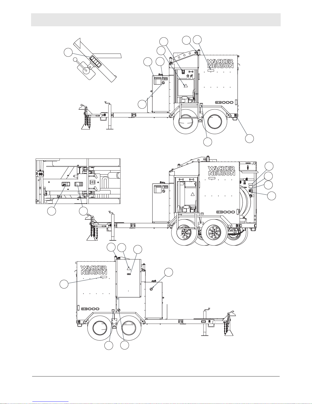
2.1 Label Locations
603
601
999
618
626
602
608
998
wc_gr008850
wc_si000643gb.fm
22
Page 23
E 3000 Labels
616
609
625
608
995
604
613
600
612
617
607
602 611
616
609
612
618
613
619
626
602
wc_si000643gb.fm
625
613
wc_gr008849
23
Page 24
Labels E 3000
2.2 Label Meanings
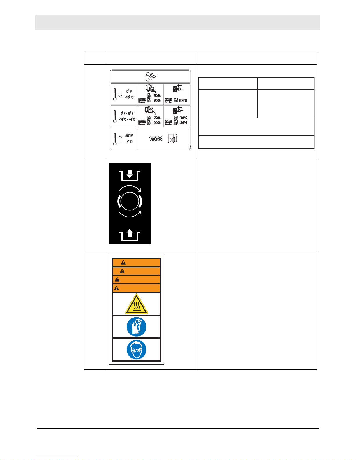
Ref. Label Definition
600
For machines powered by
the generator:
Use a 50-50 blend of #2 diesel
and #1 diesel plus additives,
or a 50-50 blend of #2 diesel
and K1 kerosene plus additives when temperatures
are below 5°F (-15°C).
Use a 70-30 blend of #2 diesel and #1 diesel plus additives or
a 70-30 blend of #2 diesel and K1 kerosene plus additives
when temperatures are in the range 5 to 25°F (-15 to -4°C).
Use a winter-blend diesel when temperatures are above
25°F (-4°C).
For machines powered by
the power utility:
Use 100% #1 diesel plus
additives or 100% K1 kerosene plus additives when
temperatures are below
are below 5°F (-15°C).
wc_gr008377
601 Turn the handle clockwise to engage the
hose reel brake.
Turn the handle counterclockwise to release
the hose reel brake.
602 WARNING!
WARNING
WARNUNG
ADVERTENCIA
AVERTISSEMENT
173199
Hot surface hazard.
Wear safety gloves.
Wear eye protection.
24
wc_si000643gb.fm
Page 25
E 3000 Labels
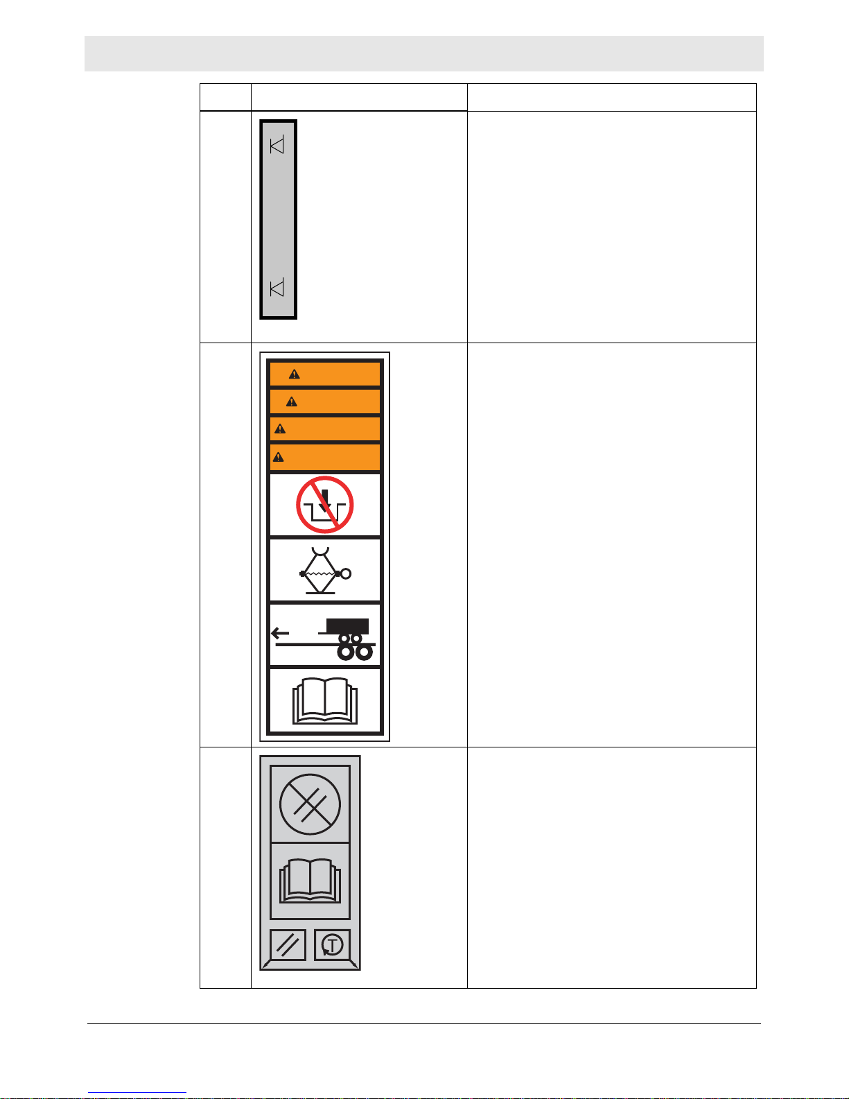
Ref. Label Definition
603 Heat Transfer Fluid level. This label indicates
the minimum and maximum level for the
Heat Transfer Fluid. This label is located
adjacent to a sight gauge on the Heat Transfer Fluid reservoir.
604 WARNING!
WARNING
WARNUNG
ADVERTENCIA
AVERTISSEMENT
Do not engage trailer jack while transporting
the machine.
Refer to the Operator’s Manual for further
instructions.
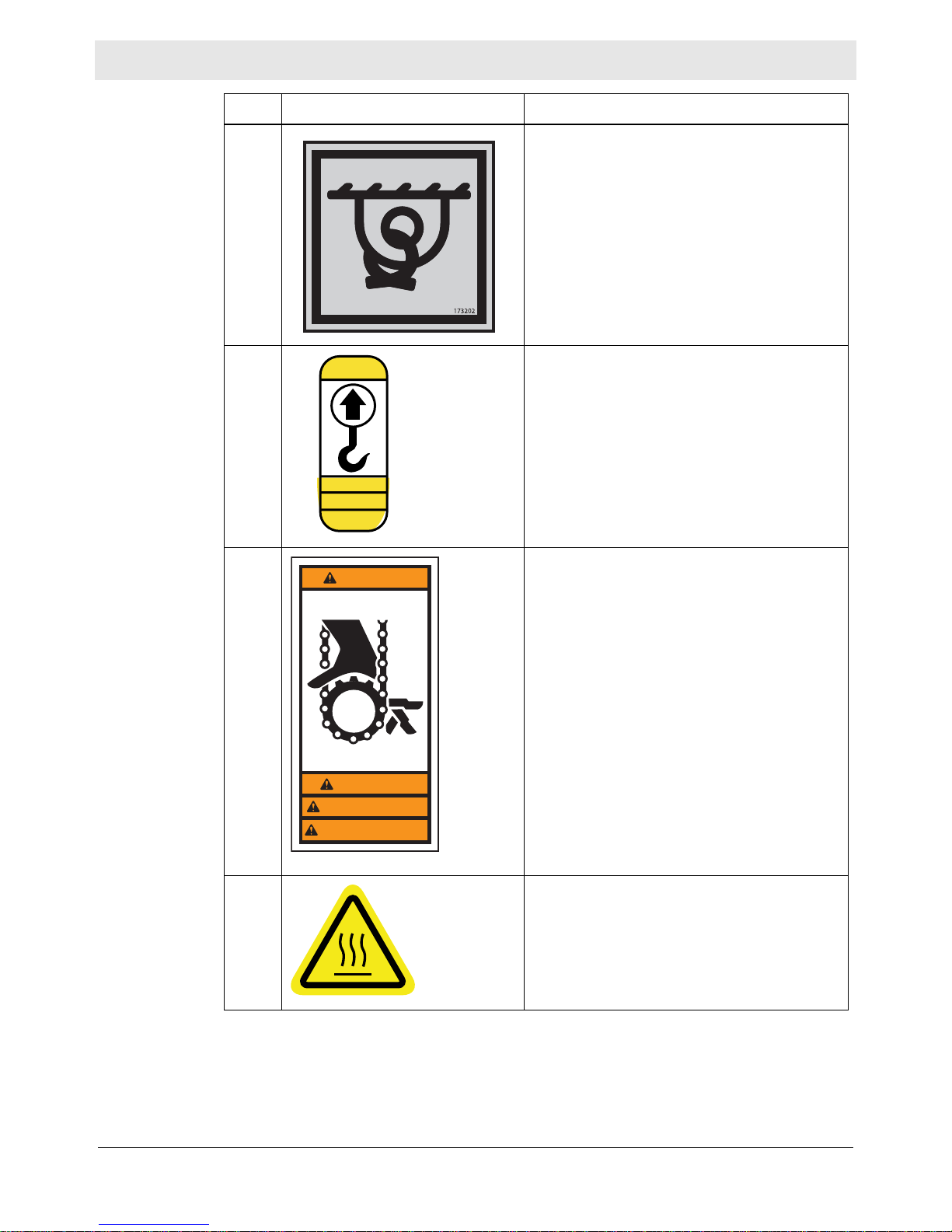
607 Do not reset.
wc_si000643gb.fm
173200
173201
Refer to Operator’s Manual.
25
Page 26
Labels E 3000
Ref. Label Definition
608 Tie-down location marker.
609 NOTICE!
CAUTION
Lift point.
Attach lifting device in this location.
VORSICHT
PRECAUCION
PRECAUTION
611 WARNING!
WARNING
Hand entanglement hazard. Moving parts
can crush and cut. Do not operate with guard
removed.
173224
WARNUNG
ADVERTENCIA
AVERTISSEMENT
612 CAUTION!
Hot surface hazard!
wc_si000643gb.fm
26
Page 27
E 3000 Labels
Ref. Label Definition
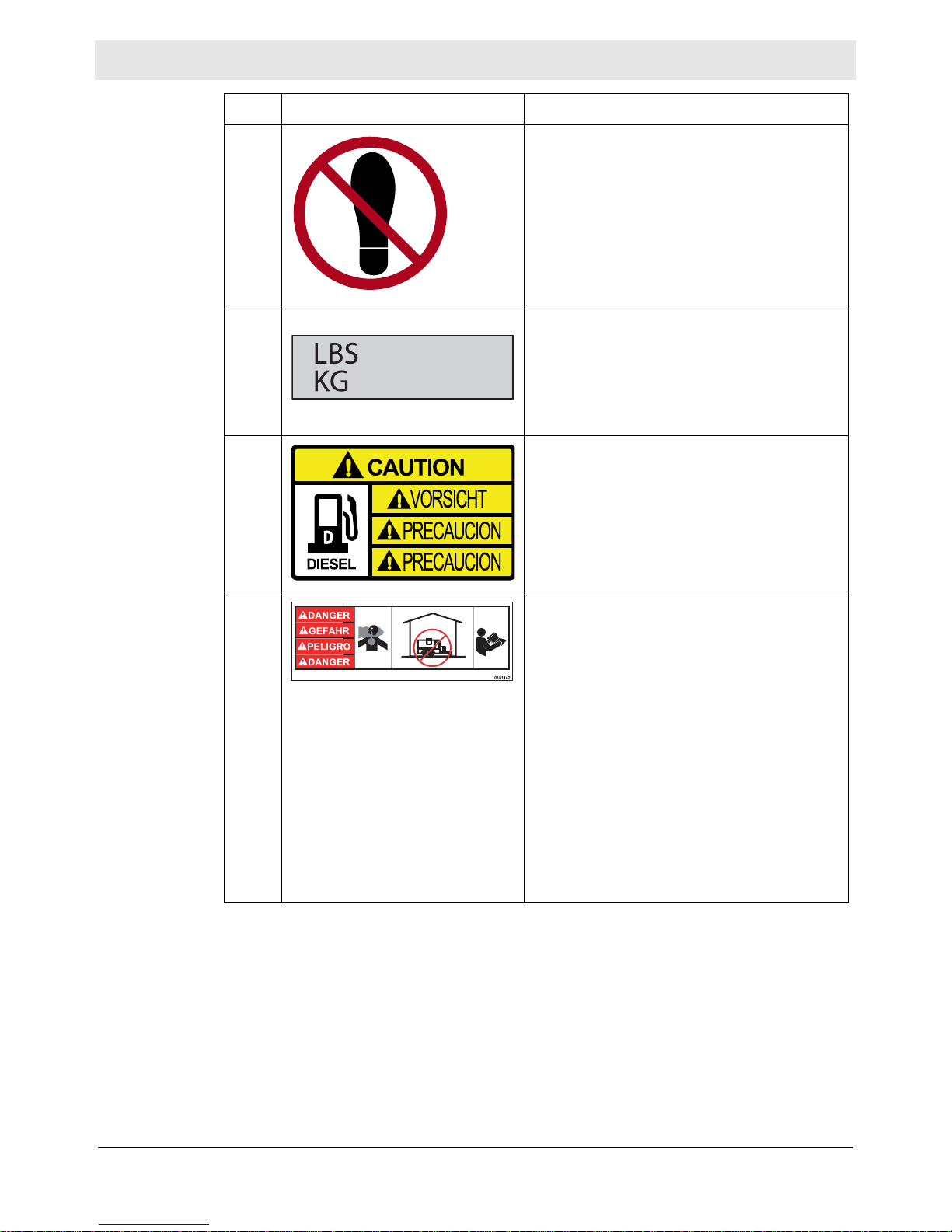
613 Not a step.
616 Weight/mass label: This label indicates the
total weight of the machine, including the
8582
trailer and a full fuel tank.
3900
617 CAUTION
This machine uses diesel fuel.
618
DANGER
Asphyxiation hazard.
Using a Hydronic Surface Heater indoors
CAN KILL YOU IN MINUTES. Generator and
burner exhaust contains carbon monoxide.
This is a poison you cannot see or smell.
Never use inside an enclosed area even if
doors and windows are open.
Only use outside away from windows, doors,
and vents.
Read manual before use.
wc_si000643gb.fm
27
Page 28
Labels E 3000
Ref. Label Definition
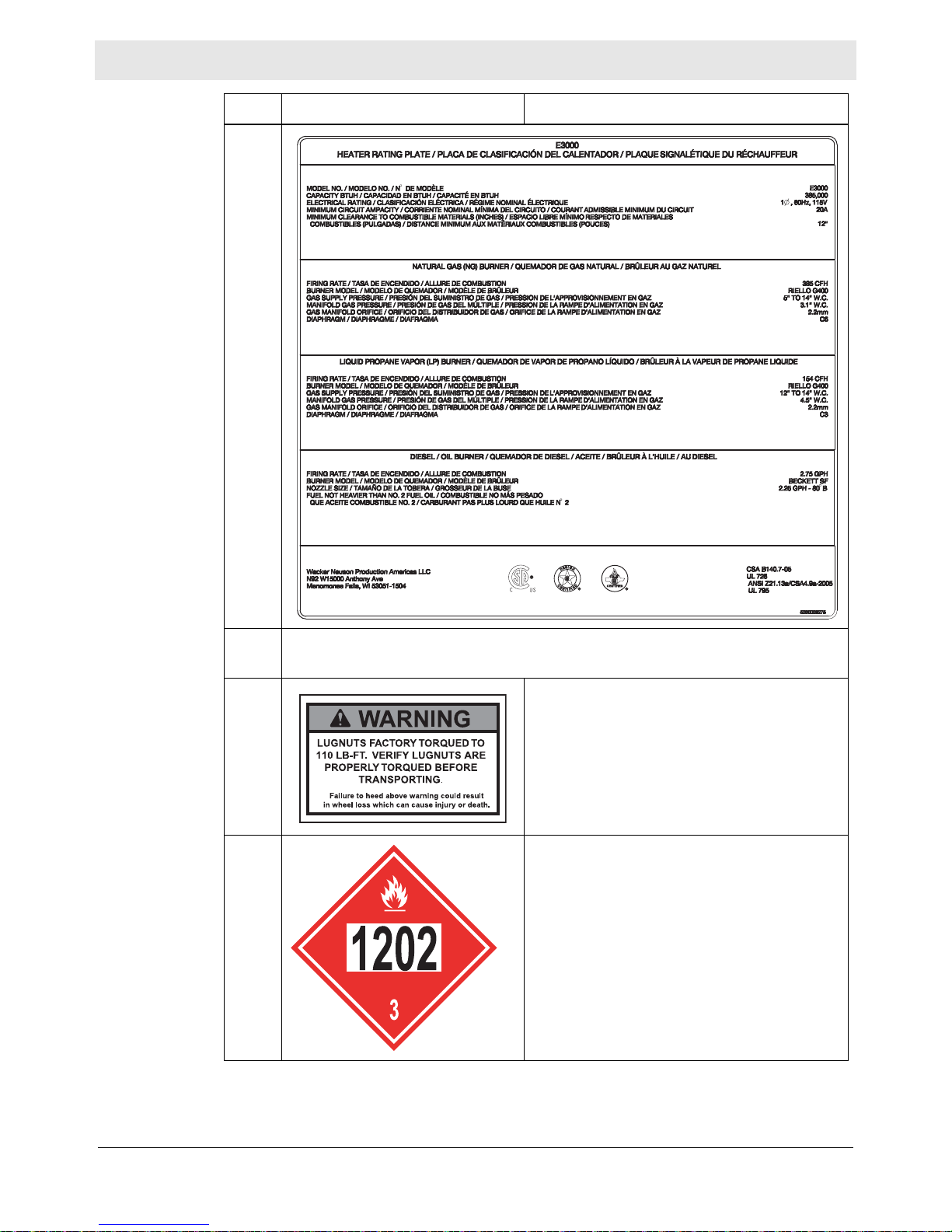
619
Machine rating label: This label indicates rating information for the machine.
625 WARNING!
Lugnuts factory torqued to 110 ft.lbs. Verify
lugnuts are properly torqued before transporting. Failure to heed above warning could
result in wheel loss which can cause injury or
death.
— Magnetic placards that display the numeric
hazardous material code for diesel fuel are
included with each machine. These placards
must be placed on three sides of the
machine during transport if the fuel tank contains any amount of fuel or fuel residue.
28
wc_si000643gb.fm
Page 29
E 3000 Labels
Ref. Label Definition
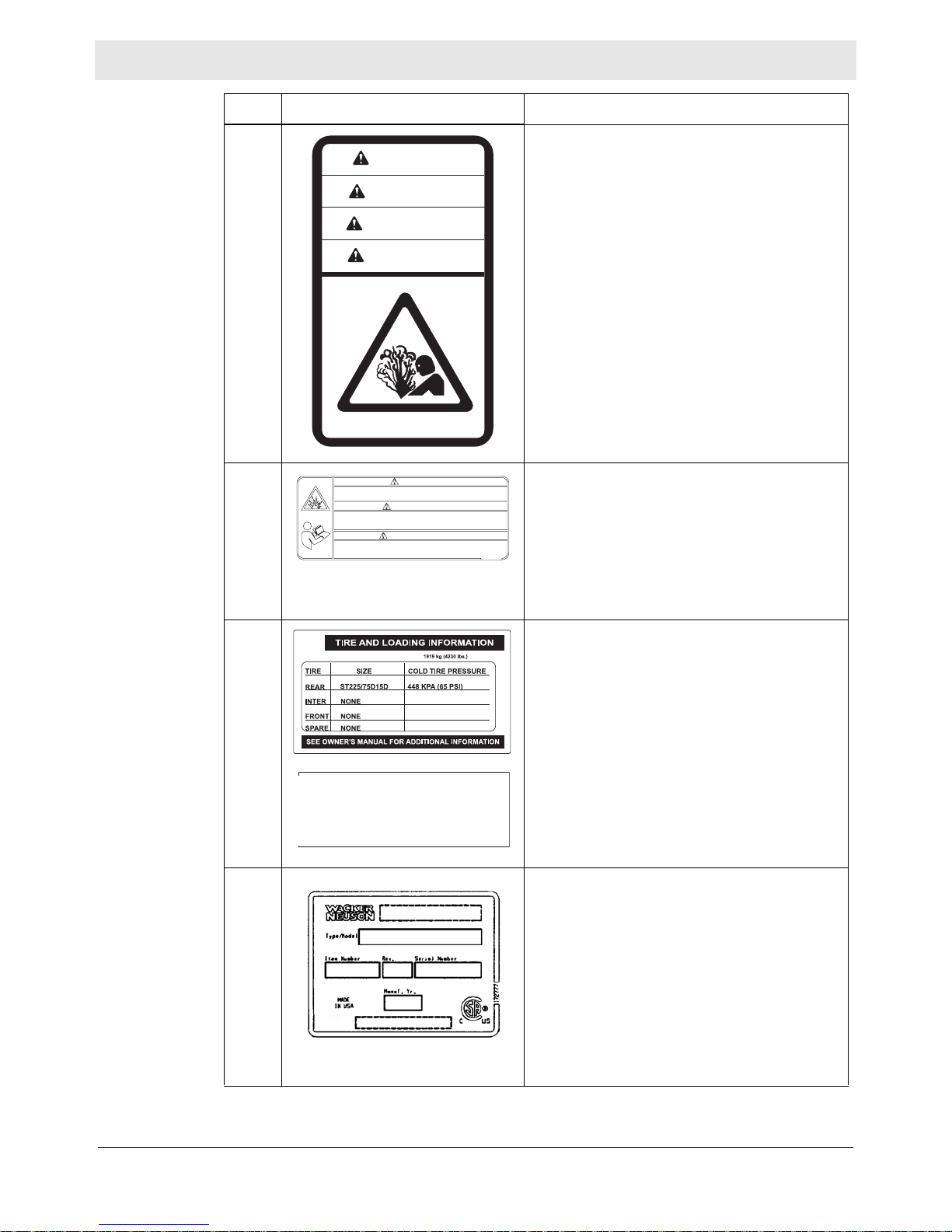
626 CAUTION!
CAUTION
VORSICHT
ATENCION
ATTENTION
183255
Pressurized contents. Do not open when hot!
995 WARNING!
Never operate in an explosive environment or near flammable vapors, fuels
or combustibles. Explosion or fire may occur. Risk of severe injury or death.
Nunca opere en un ambiente explosivo o cerca de los vapores inflamables,
gasolina o combustibles. Explosión o un incendio puede ocurrir.
Riesgo de lesiones graves o la muerte.
Ne faire jamais fonctionner dans un environnement explosif ou à proximité
des vapeurs inflammables, des carburants ou combustibles. Explosion ou un
incendie peut se produire. Risque de blessures graves ou la mort.
WARNING
ADVERTENCIA
AVERTISSEMENT
5200002911
Never operate in an explosive environment
or near flammable vapors, fuels or combustibles. Explosion or fire may occur. Risk of
severe injury or death.
998 (on trailer)
The weight of cargo should never exceed
Tire and loading information label:
This label indicates tire and loading information for the trailer.
(on trailer)
VIN label. This label displays vehicle identifi-
cation numbers and other related information.
999 A nameplate listing the model number, item
number, revision number, and serial number
is attached to each unit. Please record the
information found on this plate so it will be
available should the nameplate become lost
or damaged. When ordering parts or
requesting service information, you will
always be asked to specify the model number, item nu mber , revision number, and serial
number of the unit.
wc_si000643gb.fm
29
Page 30
Lifting and Transporting E 3000
3 Lifting and Transporting
3.1 Lifting the Machine
Requirements
Procedure
Properly rated lifting equipment (crane or hoist). See Chapter Technical Data.
Machine stopped. See topic Stopping the Machine.
All doors and access covers closed and secured.
WARNING
Crushing hazard. You may be crushed if the lifting devices fail.
f Never stand under, or get onto, the machine while it is being lifted or moved.
f Use only the designated lifting points to lift the machine.
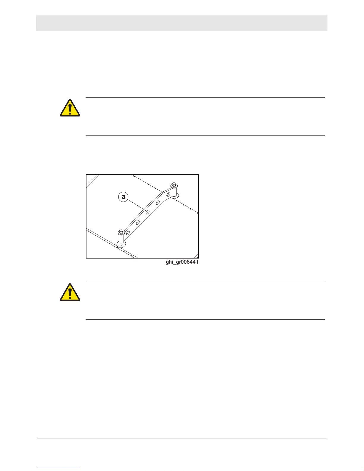
Follow the procedure below to lift the machine.
1. Attach the lifting equipment to one of the lifting eyes (a) on the machine using
hooks, shackles, and chains.
2. Lift the machine a small distance.
WARNING
Crushing hazard. An unstable machine may cause the lifting devices to fail. You
may be crushed if the lifting devices fail.
f Check for stability before continuing.
3. Check for stability. If necessary, lower the machine, reposition the lifting device,
and lift the machine a small distance again.
4. Continue lifting the machine as necessary.
30
ghi_tx001160gb.fm
Page 31

E 3000 Lifting and Transporting
3.2 Preparing the Machine for Transport on a Truck or Trailer
Requirements
Checklist
Machine stopped.
Flatbed truck or trailer capable of supporting the machine’s weight.
Chains, hooks, or straps capable of supporting the machine’s weight.
WARNING
Crushing hazard. Improperly securing the machine can lead to a crushing hazard.
f Use only the designated tie-down points to secure the machine to a truck or
trailer.
Before transporting the machine, check the following items:
Machine
Check that all accessories are securely stored within the machine.
Check that all doors and access panels of the machine are closed.
Check that all electrical supplies are disconnected from the machine.
For machines with external fuel supplies, check that all fuel supplies are
disconnected from the machine.
For machines with generators, check that the generator is shut down.
Loading and transporting equipment
Check t hat the transport vehicle or trailer can sup port the weight of the machine.
Check that the transport vehicle or trailer is wide enough to support the
machine.
Check that the wheels of the transport vehicle or trailer are chocked during the
loading process.
Check that the transport vehicle or trailer is clean and free of grease, oil, ice,
and other loose material.
If the machine is mounted to a trailer , check that the jackstand or other transport
block (piece of wood or other similar material) is available to support the trailer
tongue during transporting. Do not use the machine’s trailer jack to support the
trailer tongue during transporting.
Check that any ramps used in the loading process:
Can support the weight of the machine
Are clean and free of grease, oil, ice, and other loose material.
Are securely connected to the transport vehicle or trailer.
Are of sufficient length to keep the loading angle 15° or less.
In addition:
Check that the loading area is flat and the ground is stable.
Check the overall height of the machine once loaded. Plan your travel route so
there will be adequate clearance for overpasses, road signs, buildings, etc.
Check local regulations regarding transporting and obey these regulations.
ghi_tx001160gb.fm
31
Page 32

Lifting and Transporting E 3000
3.3 Transporting the Machine on a Truck or Trailer
Requirements
Move the
machine
Machine stopped. See topic Stopping the Machine.
All doors and access covers closed and secured.
WARNING
Crushing hazard. Improperly securing the machine can lead to a crushing hazard.
f Use only the designated tie-down points to secure the machine.
NOTICE: Do not run chains or straps across painted surfaces. Chains or straps
may damage your machine.
1. Move the machine onto the flat bed using properly rated ramps or docks.
NOTICE: The flat bed must be at least 98 inches wide.
Support the
tongue
2. Raise the tongue using the trailer jack (a).
3. Install the tongue support (b) using two 5/8 inch bolts.
NOTICE: If the supplied tongue support is missing, use any mechanism capable of
supporting the tongue weight.
4. Lower the tongue and retract the trailer jack (a) at least two inches from the
surface of the truck bed.
This procedure continues on the next page.
32
ghi_tx001160gb.fm
Page 33
E 3000 Lifting and Transporting
Continued from the previous page.
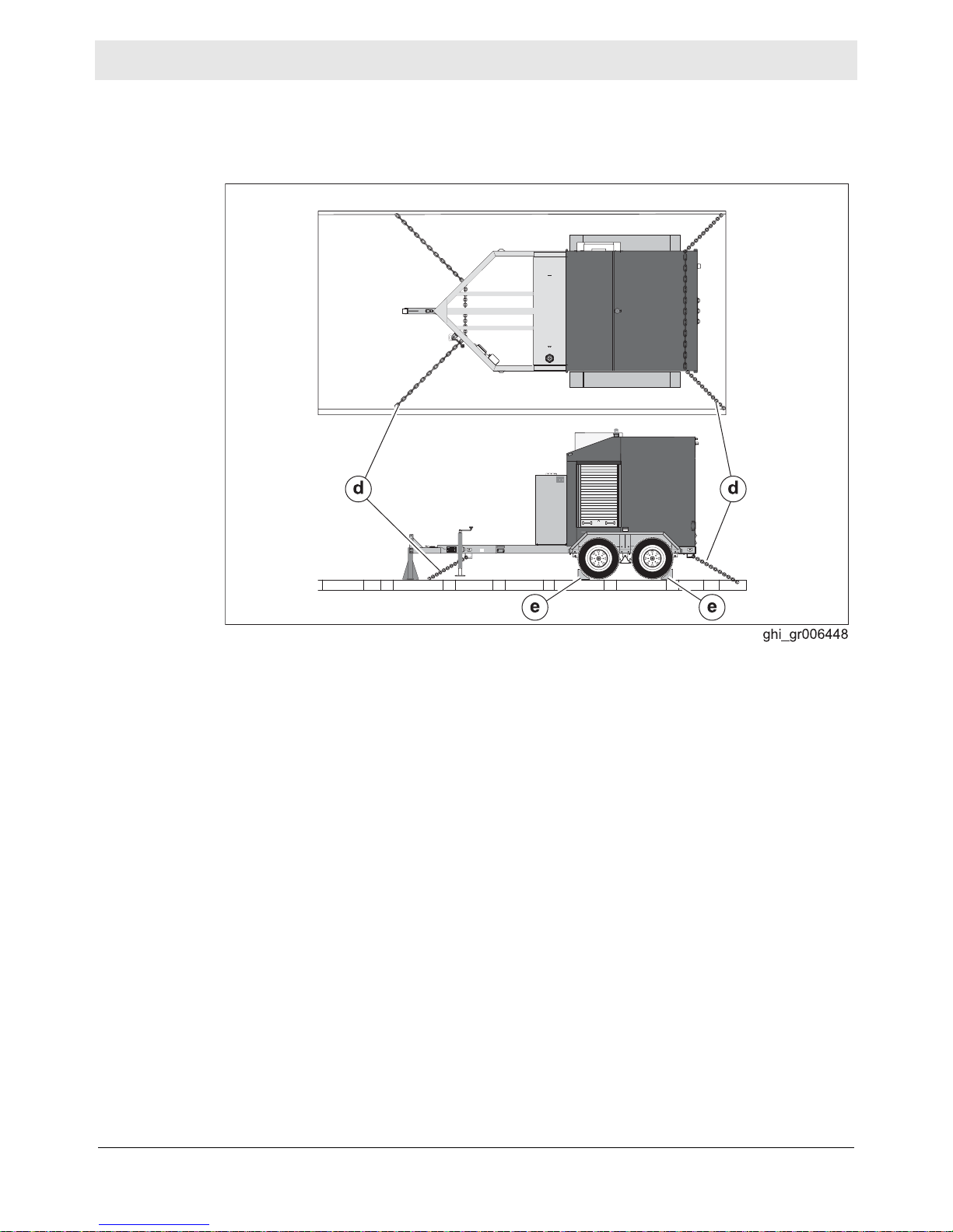
Secure the
machine
5. Install properly rated securing mechanisms (d) such as chains or straps.
6. Install chocks (e) under all four wheels.
Result
The machine is ready to be transported.
ghi_tx001160gb.fm
33
Page 34

Lifting and Transporting E 3000
3.4 Before Towing Checklist
Before towing the machine, check the licensing requirements for trailers in your
area. Also check the following items:
Hitch and coupler
Check that the towing vehicle and hitch have a rating equal to or greater than
the GVWR of the machine. See Technical Data.
Check that the hitch of the towing vehicle and coupler of the trailer are
compatible.
Check the condition of both the coupler and the hitch.
Check that all fasteners on the coupler are secure.
Check that the coupler has fresh grease applied to it.
Wheels
Check that all lug nuts are in place and are properly torqued.
Check the tread wear of the tires.
Check that the tires are inflated to the proper pressure.
Trailer operation
Check that the directional and running lights on the trailer function correctly.
Check that the safety chains of the trailer are connected to the towing vehicle
using a crisscross pattern.
Check that the trailer’s breakaway cable is attached to the towing vehicle.
Check the opera tion of the trailer brakes by braking the towing ve hicle at a slow
speed. Both the vehicle and the trailer must brake smoothly. If the trailer
pushes, check the fluid level in the surge brakes or the operation of the electric
brakes.
Test the function of the breakaway system.
ghi_tx001160gb.fm
34
Page 35

E 3000 Lifting and Transporting
3.5 Towing the Machine
WARNING
Risk of severe injury or death. Improperly torqued lug nuts can lead to loss of
wheels. Loss of wheels can cause an accident, severe injury or death.
f Tighten the lug nuts to the proper torque before towing the machine.
NOTICE: The towing vehicle must be equipped with a Class III or above hitch.
Procedure
Perform the procedure below when towing the machine.
1. Read and follow the towing safety guidelines. See topic Safety Guidelines for
Towing the Machine.
2. Complete the shut-down procedures. See topic Stopping and Packing Up the
Machine.
3. Adjust the amount of fuel in the machine to approximately 70% cap acity to avoid
fuel spillage.
4. Complete the Before Towing Checklist. See topic Before Towing Checklist.
5. Connect the machine to the towing vehicle.
6. Rotate the trailer jack to a horizontal position.
7. Tow the machine as needed.
ghi_tx001160gb.fm
35
Page 36

Lifting and Transporting E 3000
3.6 Testing the Breakaway System (Electric Brakes)
Requirements
When
Procedure
Voltmeter
Battery charger or backup battery (charged)
Test the breakaway system:
Before towing
Monthly if the machine is not in service
Perform the following procedure to test the breakaway system.
NOTICE: Disconnect the trailer wiring plug from the tow vehicle before testing.
Failure to do so will result in severe damage to the electronic brake control.
1. Connect the machine/trailer to the tow vehicle.
2. Disconnect the trailer wiring plug (a) from the tow vehicle.
a
c
b
wc_gr008470
3. Pull the breakaway pin (b) out of the brake switch (c) (to activate the brakes)
and attempt to tow the machine/trailer at a very slow speed (less than 5 mph (8
km/hr)). When activated, a properly working breakaway system will cause
substantial drag on the trailer wheels and may even cause the trailer wheels to
lock.
4. Stop the tow vehicle.
WARNING
Personal injury hazard. A faulty breakaway system may lead to an accident and
personal injury if the machine/trailer breaks away.
f Do not tow the machine/trailer if the breakaway system is faulty.
This procedure continues on the next page.
wc_gr008471
36
ghi_tx001160gb.fm
Page 37

E 3000 Lifting and Transporting
Continued from the previous page.
5. If the brakes did not function, check the voltage of the breakaway battery. To do
so:
a.Remove the cover of the battery box.
b.Remove the wires connected to the breakaway battery (d).
c.Measure the voltage. If 12–14 VDC is not measured, replace or recharge the
breakaway battery.
d
1000
F
200
V
20
2
200m
A
V- COM
VDC
wc_gr008472
6. If 12–14 VDC was measured but the brakes did not function, there is a wiring or
mechanical fault with the brakes. Repair any faults before towing.
Result
7. If the brakes function properly:
a.Reconnect the wires to the breakaway battery.
b.Reinstall the cover to the battery box.
a.Reinstall the breakaway pin (b) into the brake switch.
b.Connect the trailer wiring plug to the tow vehicle.
The procedure to test the breakaway system is now complete.
ghi_tx001160gb.fm
37
Page 38

Lifting and Transporting E 3000
3.7 Hazardous Materials Placards
Hazardous
materials
placards
The Pipeline and Hazardous Materials Safety Administration (PHMSA) requires
that hazardous materials placards be placed on this machine when transporting it
unless the fuel tank has been drained and purged of all fuel and residue.
Before transporting the machine:
1. Drain and purge the fuel tank of all fuel and fuel residue OR place placards that
display the numeric hazardous material code for diesel fuel on three sides of the
machine.
Note: The placards are included with the machine.
2. Consult the Department of Transportation (DOT), or equivalent agency, in the
states or countries in which this machine is to be transported, regarding:
Driver’s licensing requirements for transporting machines that bear hazard-
ous materials placards
Other restrictions for use of this machine
38
ghi_tx001160gb.fm
Page 39

E 3000 Lifting and Transporting
Notes
ghi_tx001160gb.fm
39
Page 40
Operation E 3000
4 Operation
4.1 External Components
10
5
4
3
7
1
2
Ref. Description Ref. Description
1 Hitch (ball or pintle) 6 Fender
2 Tie-down 7 Onan genset (option)
3 Fuel tank 8 Jack stand
4 Fuel tank cap 9 Tandem axles
5 Performance monitoring light 10 Lifting bail
8
9
6
wc_gr008851
40
wc_tx001951gb.fm
Page 41

E 3000 Operation
4.2 Internal Components
g
wc_gr008296
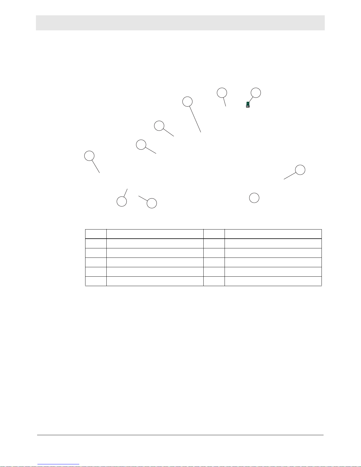
Ref. Description Ref. Description
a Hydronic heater
1
h Fill valve #3
b Burner (oil burning shown) i HTF pumps
c Suction valve #2 j Low-level shut-down device
d Fuel filter k Thermocouple
e Battery l Temper ature/pressure gauges
f Fuel sight gauge m HTF filter
g Fuel sight gauge valve n Motor (HTF pump)
1
This hydronic heater operates at zero (atmospheric) pressure and is not subject to regulations
applicable to pressurized “boilers”.
wc_tx001951gb.fm
41
Page 42
Operation E 3000
4.3 Rear Components
k
Ref. Description Ref. Description
Control panel
a
Heat Transfer Fluid (HTF) return
b
plumbing
HTF supply plumbing
c
Hose reel brake T-handle
d
Rewind system foot control pedal
e
HTF expansion tank sightglass
f
Hose reels and hose
g
Pump Pack supply connections
h
Duplex receptacle
i
Operator’s Manual holder
j
Thermal switch (snap switch)
k
—
—
42
wc_tx001951gb.fm
Page 43

E 3000 Operation
4.4 Pumps, Gauges, and Valves
Pumps and
Gauges
Valves
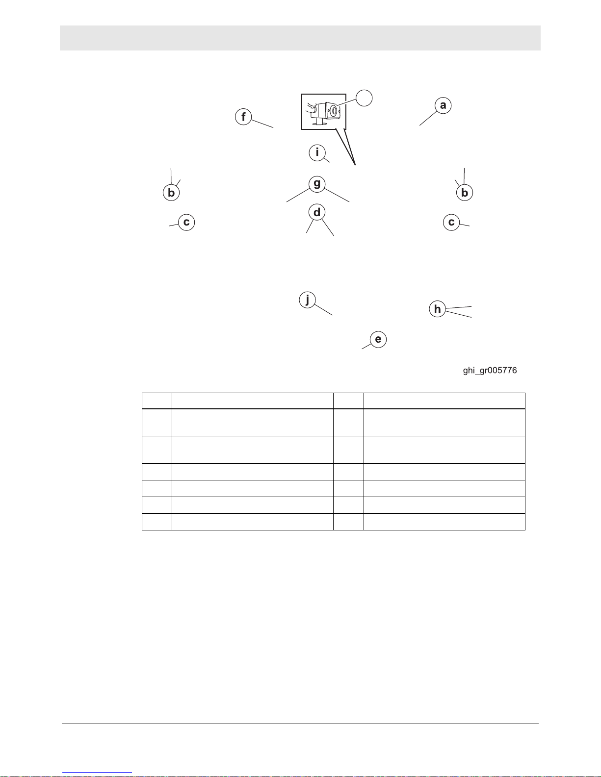
Ref. Description
aLeft pump
b Return flow indicator
c Accessory HTF return thermometer
d Main HTF return thermometer
e Check valves
f Pump pressure gauge
g Right pump
Valve # Description
1 Pump Pack supply and drain valve
2 Pump suction valve (behind hose
reel)
3 HTF fill valve (behind hose reel)
4 Left hose reel supply valve
5 Cross connect valve
6 Right hose reel supply valve
7 Pump Pack supply valve
wc_tx001951gb.fm
43
Page 44

Operation E 3000
1
2
4.5 Control Panel
m
a
b
n
c
d
e
l
k
j
hi
o
g
f
p
wc_gr008606
44
wc_tx001951gb.fm
Page 45

E 3000 Operation
4.6 Control Panel Components
Ref Description Function
a Main breaker 1 Controls power to electrical circuit 1.
b Hour meter Meters usage of the machine.
c Main breaker 2 Controls power to the pump circuit (20A)
d Circuit 2 GFCI Provides protection for the operator.
e Temperature control
f Cab light ON-OFF switch Switches electric power ON and OFF to the
g Hose rewind ON-OFF (right and
left) switch
h Burner ON-OFF switch Switches electric power ON and OFF to the
i Pump 2 ON-OFF switch Switches electric power ON and OFF to
j Pump 1 ON-OFF switch Switches electric power ON and OFF to
k HTF fill switch This momentary switch bypasses the low-
l Low level fault indicator Illuminates to indicate a low HTF level condi-
Allows the user to control the HTF target
application temperature.
Shows the actual temperature of the HTF.
cab light.
Controls power to the hose rewind motor.
This switch has two ON modes—one each in
the up and down positions. OFF mode is in
the middle position.
burner.
Pump 2.
Pump 1.
level shut-down device and provides power
to the pumps. It is used when filling the HTF
reservoir after a low level fault.
tion.
m Burner fault indicator Illuminates to indicate a burner fault condi-
n Circuit 1 GFCI Provides protection for the operator.
o Thermal switch (snap switch)
p HTF low-level reset switch (mod-
ule is located inside the auxiliary
control panel)
wc_tx001951gb.fm
45
tion.
Disconnects power to the burner circuit in the
event of an over-temperature condition. This
switch opens at 88°C (190°F). This switch
must be manually
Pressing this switch resets the low-level
shut-down device.
reset.
Page 46

Operation E 3000
4.7 Genset Control Panel
a
b
f
e
Ref Description
Oil fill cap and dipstick
a
Coolant recovery access panel
b
Coolant level sightglass
c
Control switch and status light
d
Line circuit breakers
e
Coolant fill access panel
f
c
d
wc_gr008140
46
wc_tx001951gb.fm
Page 47

E 3000 Operation
4.8 Preparing the Machine for First Use
Preparing for
first use
To prepare your machine for first use:
1. Make sure all loose packaging materials have been removed from the machine.
2. Check the machine and its components for damage. If there is visible damage,
do not operate the machine! Contact your Wacker Neuson dealer immediately
for assistance.
3. Take inventory of all items included with the machine and verify that all loose
components and fasteners are accounted for.
4. Attach component parts not already attached.
5. Add fluids as needed and applicable, including fuel, engine oil, and battery acid.
6. Move the machine to its operating location.
4.9 Breaking in the Genset
Background
Procedure
New gensets require a break-in period for the engine. If you are the first owner of
this machine, or the genset’s engine has just been rebuilt, break in the engine as
stated below.
1. Check that the engine oil level is correct. Check that the engine oil viscosity is
appropriate for the temperature conditions. Change the oil if it is not appropriate
for the temperature conditions.
2. Operate the genset at approximately 1/2 rated power for the first two hours.
3. Operate the genset at approximately 3/4 rated power for two more hours.
4. Check the engine oil level every four hours (or twice daily) during the first 24
hours of operation.
5. Change the engine oil and filter after the first 50 hours of operation.
wc_tx001951gb.fm
47
Page 48

Operation E 3000
4.10 General Sequence of Operation
Follow the sequence of operation below. Refer to the specific topic for details.
Task When/Where See Topic
1. Check HTF level. Before leaving for the job site.
2. Check fuel level. 4.13 / 4.15
3. Position the machine. At the job site. 4.14
4. Perform pre-starting checks. 4.15
5. Connect power. 4.16
6. Start the generator (if equipped) 4.17
7. Power up the machine. 4.18
8. Run the machine. —
a. Preheat the HTF (if necessary). 4.19
b. Initiate HTF flow. 4.20
c. Unwind and position the hoses. 4.22 / 4.23
d. Monitor the operating parameters. 4.24
Or, when at the job site before
daily operation.
4.11 / 4.15
e. Rewind the hoses. 4.25
9. Shut down and pack up the machine. 4.26
48
wc_tx001951gb.fm
Page 49

E 3000 Operation
4.11 Checking the HTF Level
When
Prerequisites
Procedure
If low
Before leaving for the job site, or
Before beginning operation at the job site
The machine is level.
The machine is cool.
The Heat Transfer Fluid (HTF) level must be between the marks on the
sightglass (c).
If the HTF level is low, HTF must be added. Filling the HTF reservoir requires
electric power to the machine and knowledge of the machine’s operation.
Familiarize yourself with the function of the machine’s controls, then see topic
Filling the HTF Reservoir for detailed instructions.
wc_tx001951gb.fm
49
Page 50

Operation E 3000
4.12 Recommended Fuel
Low ambient temperatures cause diesel fuels to gel. Gelled fuels will cause burner
ignition failure and/or burner fuel pump damage. Always use the proper fuel for the
conditions.
Fuel Blend Guide
Lowest expected ambient
temperature °F (°C)
Below 5 (-15)
Generator-powered Shore-powered
50-50 blend of #2 diesel
and #1 diesel, plus
additives
OR
50-50 blend #2 diesel and
K1 kerosene, plus
additives
100% #1 diesel plus
additives
OR
100% K1 kerosene,
plus additives
70-30 blend of #2 diesel and #1 diesel, plus additives
5 to 25 (-15 to -4)
Above 25 (-4) Winter-blend diesel
70-30 blend of #2 diesel and K1 kerosene,
OR
plus additives
NOTICE: Do not use B20 or any other type of biodiesel fuel in this machine.
CAUTION
Fire hazard.
f Do not use gasoline, crankcase oil, or any oil containing gasoline.
50
wc_tx001951gb.fm
Page 51

E 3000 Operation
4.13 Refueling the Machine
Requirements
Procedure
Machine shut down
Machine level with the ground
Diesel fuel supply
Perform the procedure below to refuel the machine.
Note: On models with generators, it is not necessary to fill the generator’s fuel
tank. Both the burner and the generator use the machine’s fuel tank.
1. Lift the lever (a) on the fuel cap.
a
wc_gr008446
2. Rotate the lever counterclockwise until it stops.
wc_gr008447
3. Remove the fuel cap from the tank.
b
wc_gr008448 wc_gr008599
4. Fill the tank with the appropriate grade of fuel for the weather conditions until the
gauge (b) reads full. Leave room within the tank for possible fuel expansion.
CAUTION
Fire and health hazard. Fuel expands when heated. Expanding fuel in a overly-full
tank can lead to spills and leaks.
f Do not overfill the fuel tank.
5. Reinstall the fuel cap.
Result
wc_tx001951gb.fm
The procedure to refuel the machine is now complete.
51
Page 52

Operation E 3000
4.14 Positioning the Machine
DANGER
Asphyxiation hazard.
Exhaust gas from the burner contains carbon monoxide, a deadly poison you
cannot see or smell. Exposure to carbon monoxide can kill you in minutes.
f Position the machine so that burner exhaust will not enter any nearby
structures.
WARNING
Fire hazard. Do not move the machine while it is running.
f Shut down the machine before moving or repositioning it.
WARNING
Fire hazard. Machines positioned on a hill or an incline may slide, break away or
roll over.
f Do not position the machine on a hill or an incline.
CO Alarms
Requirements
WARNING
Explosion and fire hazard. Risk of severe injury or death.
f Do not operate the machine near flammable vapors, fuels, or combustibles.
Because this machine produces carbon monoxide (CO), Wacker Neuson
recommends that CO alarms be installed in all structures in close proximity to the
machine. CO alarms provide an extra measure of protection against this poison
that you cannot see or smell.
Install battery-operated CO alarms or plug-in CO alarms with battery backup,
according to the manufacturer’s instructions. CO alarms should be certified to the
requirements of the latest safety standards (UL 2034, IAS 6-96, or CSA 6.19.01).
Test the CO alarm batteries monthly.
Position the machine:
so that burner exhaust will not enter nearby structures.
so that the machine does not block traffic.
so that the machine is not close to any combustible material or flammable vapor .
so that all of the machine’s access doors/panels may be accessed.
so that HTF hoses do not pose tripping hazards, and so the HTF hoses cannot
be damaged by machines or other equipment on the job site.
This procedure continues on the next page.
52
wc_tx001951gb.fm
Page 53

E 3000 Operation
Continued from the previous page.
Procedure
Result
Perform the following procedure to position the machine.
1. Place the machine near the application area (a) on solid, stable, and level
ground.
E
TI
N
TIE
DOW
N
TIE
DOWN
DOW
b
wc_gr008529
2. For machines with trailers, install chocks (b) under the wheels.
The machine is now properly positioned.
E
TI
WN
DO
wc_tx001951gb.fm
53
Page 54

Operation E 3000
4.15 Pre-Starting Checks
Requirements
Checks
Machine properly positioned
Power connected to the machine
Before starting the machine, check the following items:
Fuel System
Fuel sight gauge valve
(a)
f Check that the fuel sight
gauge valve is open.
Fuel sight gauge
(b)
f Check that the fuel tank is
full.
Quick connects
(d)
f Check that the quick-con-
nect couplings are secure.
b
a
wc_gr008602
Heat Transfer Fluid (HTF) System
d
wc_gr008605
54
wc_tx001951gb.fm
Page 55

E 3000 Operation
Suction valve (#2)
f Check that suction valve (#2)
is open.
HTF fill valve
(#3)
f Check that HTF fill valve (#3)
is closed and locked with the
locking pin.
NOTICE:
remain closed and locked during
normal operation. An open HTF fill
valve will cause HTF leakage.
The HTF fill valve must
HTF sight gauge (c)
f Check that the HTF level is
within the operating range.
NOTICE:
with low HTF will damage the
pumps.
Starting the machine
wc_tx001951gb.fm
HTF Hose connections (e)
f Check that all HTF hose
quick-connects are secure.
55
Page 56

Operation E 3000
Hydronic heater
(f)
f Inspect for signs of exhaust
leaks. See topic
Replacing the Rope Gasket.
Inspecting/
Genset (g) (if equipped)
f Check oil level. See topic
Checking the Engine Oil.
f Inspect for signs of fuel and
exhaust leaks
.
f
wc_gr008603
g
Result
wc_gr008141
The machine is ready to have power applied.
56
wc_tx001951gb.fm
Page 57

E 3000 Operation
1
2
4.16 Connecting Power to the Machine
Prerequisites
Extension
cords
Procedure
Power source
Machine properly positioned
WARNING
Fire hazard and electric shock hazard. The use of undersized extension cords can
lead to fire and electric shock. Fire and electric shock can cause severe injury.
f Do not use undersized extension cords.
Restrictions for extension cords:
Use only 3-wire type extension cords with heavy-duty plugs.
The maximum length of extension cord usage per circuit is 30 m (100 ft).
Use 12-gauge extension cords for lengths up to 15 m (50 ft).
Use 10-gauge extension cords for lengths up to 30 m (100 ft).
Follow the procedure below to connect power to the machine.
1. Move both circuit breaker switches (a and b) to the OFF position.
a
b
c
d
POWER 2
POWER 1
wc_gr008601
2. Connect the main power cords (c) to a properly-rated power source or to the
generator (d) if included.
Result
Power has now been connected.
wc_tx001951gb.fm
57
Page 58

Operation E 3000
4.17 Starting and Stopping the Generator
Background
Starting
Only general starting and stopping procedures for the gene rator are included in this
manual. See the generator manufacturer’s operation manual for detailed
procedures.
Perform the procedure below to start the generator.
1. Move the circuit breaker switches on the genset to the OFF position.
2. Prime the fuel system if needed. The fuel system will need to be primed if:
Fuel system has run dry
Fuel system has been drained
The fuel filter has been changed
The genset has not been run for several weeks
f To prime the fuel system: Press and hold the control switch in the “S top / Prime”
position. The fuel pump will start two seconds after the control switch is initially
placed in the “Stop / Prime” position. Continue holding the control switch for at
least one minute.
Start /
Preheat
Stopping
Stop /
Prime
O
wc_gr007811
3. Press and hold the control switch in the “Start / Preheat” position. The genset
will first preheat (for up to 15 seconds depending on how cold it is). Then, the
starter will engage and the engine will start.
NOTICE: Do not crank the engine for more than 30 seconds at a time. Wait at
least two minutes before cranking the engine again.
Perform the procedure below to stop the genset.
1. Move the generator circuit breakers to the OFF position.
2. Allow the genset to run two minutes to cool down.
3. Press the control switch to the “Stop / Prime” position.
58
wc_tx001951gb.fm
Page 59

E 3000 Operation
1
2
4.18 Applying Power to the Machine
Requirements
Procedure
Pre-starting checks have been completed
Power connected to the machine
Follow the procedure below to apply power to the machine.
1. Move both circuit breaker switches (a) to the ON position.
wc_gr008607
2. Check that the indicator lights of both GFCIs (b) are off. Press the “RESET”
button of the GFCI if its indicator light is ON.
3. Check that the low-level-fault indicator light (c) is OFF. If this light is ON, add
Heat Transfer Fluid (HTF) to the reservoir. See topic Filling the HTF Reservoir.
Result
4. Check that the displays of the temperature controller (d) illuminate. If the
displays of the temperature controller do not illuminate, there is a problem with
the GFCI 1 or with the wiring to the temperature controller. Disconnect the main
power supply and rectify the problem before continuing.
The machine is ready for operation.
wc_tx001951gb.fm
59
Page 60

Operation E 3000
4.19 Preheating the HTF
NOTICE: Starting the machine with frozen or partially frozen Heat Transfer Fluid
(HTF) will permanently damage the pumps. Preheat the HTF when ambient air
temperature is below -26°C (-15° F).
Requirements
Procedure
HTF reservoir full
Machine powered up
Follow the procedure below to preheat the HTF.
1. Use the up and down arrows (a) on the temperature controller to set the HTF
temperature to 100°F (40°C). This is the set point temperature.
b
ghi_gr006377
2. Move the burner ON-OFF switch (b) to the ON position. The following sequence
occurs:
a.The burner motor starts after a 5-second delay.
b.The burner fires after a 15-second delay.
c.The burner will operate, with little or no visible exhaust smoke, until the HTF
reaches the set point temperature, at which time, the burner will stop firing.
d.The burner will re-fire if the set point temperature is increased or the
temperature of the HTF falls below 100°F (40°C).
Note: The temperature of the HTF is displayed (b) in red.
Result
When the temperature controller displays “100.0” (b) the HTF is preheated.
60
wc_tx001951gb.fm
Page 61

E 3000 Operation
4.20 Initiating HTF Flow
Requirements
Procedure
Heat Transfer Fluid (HTF) preheated. See topic Preheating the HTF.
Gloves
CAUTION
Burn hazard. The hoses and components of the plumbing system may be very hot.
Hot hoses and hot plumbing components may cause burns.
f Wear gloves when handling hot hoses or hot plumbing components.
Note: If you are using accessories, see Chapter “Accessories”.
Follow the procedure below to initiate HTF flow.
1. Close and lock valve #3. This is the fill valve.
v
2. Open valve #2. This is the suction valve.
3. Open valve #4 and valve #6. These are the hose reel supply valves.
This procedure continues on the next page.
wc_tx001951gb.fm
61
Page 62

Operation E 3000
Continued from the previous page.
4. Move the left pump ON-OFF switch (d) to the ON position.
75
180
5. Check the pump pressure gauge (e). The following should occur:
During the first minute of operation, the pressure should build to as high as
170 psi.
NOTICE: If the HTF reaches 170 psi (11.7 bar) after only a second or two of
operation, there is a problem. Shut down the machine and rectify the problem
before continuing.
Once flow is established, pressure should be: 125–140 psi (8.6–9.6 bar).
When the HTF is warm, operating pressure should be: 90–110 psi (6.2–7.6
bar).
6. Check the HTF flow indicator (f). The flow indicator should be spinning. If it is
not, there is a problem. Shut down the machine and rectify the problem before
continuing.
7. Repeat steps 4–6 for the right pump.
Result
HTF is now flowing.
4.21 Setting the Operating Temperature
Operating
temperature
Once the HTF is preheated, set the temperature controller to the operating
temperature. Use the chart below as a guide.
Operation type Recommended Temperature Setting
Ground thawing
Concrete curing
Air heating
80°C (180°F)
7°C (20°F) above the desired temperature of the con-
crete
80°C (180°F)
62
wc_tx001951gb.fm
Page 63

E 3000 Operation
4.22 Unwinding and Positioning the Hoses
Requirements
Procedure
HTF preheated if applicable
HTF flow initiated
CAUTION
Burn hazard. The hoses and components of the plumbing system may be very hot.
Hot hoses and hot plumbing components may cause burns.
f Wear gloves when handling hot hoses and plumbing components.
Follow the procedure below to unwind and position the hoses.
1. Rotate the T-handle (a) counter-clockwise to unlock it.
:
Result
wc_gr008530
wc_gr008535
2. Pull the hose (b) off the reel by hand and place it in the application area. See
topic Hose Spacing Guidelines for hose spacing recommendations based on
application.
The hose is now positioned and the machine is operating.
NOTICE: The machine must be periodically monitored during operation to ensure
system efficiency. See topic Monitoring the Operating Parameters.
wc_tx001951gb.fm
63
Page 64

Operation E 3000
4.23 Hose Spacing Guidelines
Background
Hose spacing
diagram
When laying hose in the application area, the space between individual lines of
hose significantly affects the progress of the application. Although it is impossible
to predict the ambient conditions for each job site, Wacker Neuson Corporation
recommends observing the following guidelines to maximize efficiency.
Refer to the diagram and table below when placing hoses in the application area.
Note: Adjustments may be necessary to achieve maximum efficiency.
Application Distance (d) Description
Frost prevention 91.5 cm (36 in.) Prevents frost in the application area.
Concrete curing 61 cm (24 in.) Allows concrete to cure.
Excavation thaw 61 cm (24 in.) Partially thaws the ground for excavation.
Compaction thaw 45.7 cm (18 in.) Completely thaws the ground for compaction.
Accelerated thaw 30.5 cm (12 in) Up to 50% faster than compaction thaw.
Note: To increase heat penetration, cover the hoses with a plastic vapor barrier
and two layers of insulated blankets. For concrete curing, cover the concrete with
plastic, place the hoses on top of the plastic, then cover the hoses with two layers
of insulated blankets.
Note: The hoses may be positioned vertically along concrete framing walls for
curing applications. Contact Wacker Neuson Application Support for more
information.
64
wc_tx001951gb.fm
Page 65

E 3000 Operation
4.24 Monitoring the Operating Parameters
Background
Parameters
Monitor the machine while it is operating to ensure safe and efficient operation.
Monitor the following parameters every 8–24 hours.
Parameter Notes
Fuel level Add fuel as needed.
HTF level Add HTF as needed.
HTF operating pressure Operating pressure: 90–110 psi.
If operating pressure is higher than 110 psi, check for
kinked hoses.
If operating pressure is less that 90 psi, check HTF level.
HTF return temperature The HTF return temperature tells you how much heat is
being transferred. It can also tell you when a thawing process is complete, as very little heat will be transferred at
that point. Consult Wacker Neuson Product Support for
detailed information.
Strobe light Flashing strobe signifies that all systems are OK.
wc_tx001951gb.fm
65
Page 66

Operation E 3000
4.25 Rewinding the Hoses
Requirements
Procedure
All accessories off, if applicable
Machine turned on
CAUTION
Burn hazard. The hoses and components of the plumbing system may be very hot.
Hot hoses and hot plumbing components may cause burns.
f Wear gloves when handling hot hoses and plumbing components.
Perform the procedure below to rewind the hose.
Note: Turn the pump ON. Turning the pump on—to circulate warm HTF through
the hose—will aid in handling of the hose.
1. Turn the T-handle (a) counterclockwise to unlock the hose reel.
b
wc_gr008530
2. Remove the foot pedal (b) and place it on a firm, flat, and dry surface.
3. Move the hose rewind ON-OFF switch (c) to the RIGHT or LEFT position
depending which reel you are working with.
Note: The rewind motor will start but will not rotate the hose reel until the clutch is
engaged.
wc_gr008531
b
wc_gr008532
4. Press down on the foot pedal to engage the clutch. The hose reel will rotate.
wc_gr008533
5. Guide the hose evenly onto the hose reel as it rotates.
This procedure continues on the next page.
66
wc_tx001951gb.fm
Page 67

E 3000 Operation
Continued from the previous page.
NOTICE: Disengage the clutch before reaching the hose end. Failure to comply
may damage the machine.
6. Release the foot pedal to disengage the clutch before reaching the hose end.
7. Manually wind the remainder of the hose onto the reel.
Result
wc_gr008535
wc_gr008534
8. Engage the hose reel brake by turning the T-handle (a) clockwise.
9. Return the foot pedal (b) to its storage location.
b
wc_gr008531
10.Turn the pump off.
11.Move the hose rewind ON-OFF switch (c) to the OFF position.
The hoses are now wound onto the hose reel and the machine is ready to be shut
down. See topic Shutting Down and Packing Up the Machine.
wc_gr008532
wc_tx001951gb.fm
67
Page 68

Operation E 3000
0
0
4.26 Shutting Down and Packing Up the Machine
Shutting
down
Perform the procedure below to shut down the machine.
1. Turn off all accessories if applicable.
2. Rewind the hoses. See topic Rewinding the Hoses.
3. Move the burner ON-OFF switch (a) to the OFF position.
b1 b2
LEFT
PUMP
4. Move the pump ON-OFF switches (b
RIGHT
PUMP
a
wc_gr008536
and b2) to the OFF position.
1
5. Move the circuit breaker ON-OFF switches (e) to the OFF position.
The machine is now shut down and ready to be packed up.
Packing up
the machine
Perform the following procedure to pack up the machine.
1. Disconnect and store all accessories.
2. Disconnect power from the machine.
3. Close and lock all doors.
Result
The machine is now ready to be stored.
wc_gr008537
wc_tx001951gb.fm
68
Page 69

E 3000 Operation
4.27 Resetting a Low HTF Fault
Requirements
Background
Procedure
Genuine Wacker Neuson Heat Transfer Fluid, or
Dowfrost HD 50 Heat Transfer Fluid
NOTICE: Use only factory-recommended Heat Transfer Fluid (HTF). Failure to do
so may damage the machine.
The HTF reservoir includes a sensor that will trigger the low-level shut-down device
to stop the machine’s function if the HTF falls below the minimum operational
capacity. During a low HTF level condition the following occurs:
The control panel low level fault light illuminates
Power is cut to the burner
Power is cut to the pumps
The low-level shut-down device “LOW WATER” light illuminates
Follow the procedure below to reset a low HTF fault.
1. Move the burner switch to the OFF position.
2. Move the pump switches to the OFF position.
3. Clean the fill hose.
4. Remove the locking pin, then open valve #3 and close valve #2 simultaneously.
5. Place the open end of the fill hose (a) into a container full of HTF.
6. Open valve #6 (right hose reel supply valve).
This procedure continues on the next page.
wc_tx001951gb.fm
a
wc_gr008538
69
Page 70

Operation E 3000
Continued from the previous page.
7. Lift and hold the HTF fill switch (b) in the ON position (I) and watch the HTF
reservoir sightglass (c)—release the HTF fill switch when the HTF level is seen
in the HTF reservoir sightglass.
NOTICE: Do not overfill the HTF reservoir. Doing so may damage the machine.
8. Press and release the “RESET” button (d) on the low-level shut-down device.
The following will occur:
The “POWER” (green) (f) and “LOW WATER” (red) (e) lights will blink for fif-
teen seconds while the low-level shut-down device performs a self-diagnostic test.
After 15 seconds, the “LOW W ATER” light will go out—the “POWER” light will
stay on.
The low HTF level indicator will go out.
Power will be returned to the pumps.
Power will be returned to the burner.
9. Move the right pump switch to the ON position (I) and continue to fill the HTF
reservoir until the HTF level is between the two marks on the HTF reservoir
sightglass.
NOTICE: Do not overfill the HTF reservoir. Doing so may damage the machine.
This procedure continues on the next page.
70
wc_tx001951gb.fm
Page 71

E 3000 Operation
Continued from the previous page.
10.Move valve #3 to the normal position.
1 1.Remove the fill hose from the HTF cont ain er and allow any HTF within the ho se
to drip back into the container. Cap the fill hose if a cap is provided.
12.Move the fill hose to its storage location under the hose reel.
13.Open valve #2 and close valve #3 simultaneously.
Result
The low HTF level fault has been reset and the HTF reservoir has now been filled.
You may now resume operation of the machine.
wc_tx001951gb.fm
71
Page 72

Operation E 3000
4.28 Quick-Connect Coupling Usage and Care
CAUTION
Burn hazard. The hoses and components of the plumbing system may be very hot.
Hot hoses and hot plumbing components may cause burns.
f Wear gloves when handling hot hoses and hot plumbing components.
Precautions
Cleaning
Using
Do not join or separate quick-connect couplings when the pressure gauge
indicates that the system is pressurized.
Do not join or separate quick-connect couplings when the HTF temperature is
above 48°C (120°F).
Do not use damaged quick-connect couplings.
Do not use dirty or contaminated quick-connect couplings.
Do not lubricate the quick-connect couplings.
Follow the procedure below to clean the quick-connect couplings. Do so before
and after each use.
1. Clean both the male
(a)
and female coupling
(b)
by rinsing each with clean water.
2. When the couplings are clean, inspect seals and gaskets and replace them if necessary.
3. After cleaning the couplings, install cap s or protective covers on the couplings to
protect them.
Follow the procedures below to use the quick-connect couplings.
1. Pull back and hold the locking collar (c) on the female coupling (b).
2. Insert the male coupling (a) into the female coupling.
3. Release the locking collar. The couplings will lock together.
To release the couplings:
1. Pull back and hold the locking collar (c) on the female coupling (b).
2. Pull the male coupling from the female coupling.
3. Release the locking collar.
72
wc_tx001951gb.fm
Page 73

E 3000 Operation
4.29 Operating States of the Beckett Burner Controller
Operating
10 30
Ignition
State
Standby
carryover
Run
wc_gr007662
Burner states
The burner control has several states that it sequences through during normal
operation. These operating states are described below.
.
State Action or Function
Standby As soon as power is supplied to the burner control, the burner control
Valve-on
delay
(pre-time)
Trial-for-
ignition
enters the standby state in which it will remain until there is a call for
heat or power is disconnected.
When the setpoint of the temperature controller is set to a temperature
higher than that of the heat transfer fluid, the output contacts of the temperature controller close, completing a circuit between the two te rminals
labeled “T” of the burner control. This is the call for heat. The burner
control enters the valve-on-delay state.
The valve-on-delay state lasts 15 seconds. During this state:
Power is sent to the burner motor/fuel pump.
Power is sent to the electrodes.
If the cad cell detects flame at the end of the valve-on-delay state, the
burner control goes into the lockout state.
The trial-for-ignition state immediately follows the valve-on-delay state.
During this state:
The fuel shut-off valve is opened (energized).
Pressurized fuel atomizes at the burner nozzle.
The atomized fuel is ignited by the electrodes.
The burner fires and the flame is monitored by the cad cell.
If flame is detected, the burner control moves to the ignition carryover
state.
wc_tx001951gb.fm
If flame is not detected within 15 seconds:
The burner control enters the lockout state.
Power is disconnected from the fuel shut-off valve, electrodes, and
the burner motor.
73
Page 74

Operation E 3000
State Action or Function
Ignition
carryover
The ignition carryover state starts as soon as the flame is established.
During this state:
The fuel shut-off valve is open (energized).
Pressurized fuel atomizes at the burner nozzle.
The atomized fuel is ignited by the electrodes.
The electrodes stay powered for up to 10 seconds after flame is
sensed.
When the ignition carryover state has elap sed:
The ignition transformer is shut off.
The burner control enters the run state.
If the flame is lost during the ignition carryover state:
If the lockout time has not expired, the burner control returns to trial-
for-ignition state.
If the lockout time has expired, the burner control enters the recycle
mode.
Run The run state starts and continues once the ignition carryover state has
elapsed. During this state:
The fuel shut-off valve is open (energized).
Pressurized fuel atomizes at the burner nozzle.
The flame is monitored by the cad cell.
When the setpoint is reached (call for heat satisfied), the burner control
enters the burner-motor-of f delay state.
If the flame is lost during the run state:
The burner control enters the recycle mode.
Burner-motor-
off-delay
The burner-motor-off-delay state starts immediately after the setpoint is
reached, i.e., the call for heat has been satisfied. The time of this state
is 30 seconds. During this state:
The output contacts of the temperature controller open, interrup ting
the circuit between terminals labeled “T”.
The fuel shut-off valve closes (de-energizes).
The burner motor runs until the burner-motor-off delay expires, then
the burner motor turns off.
The burner control returns to the idle mode.
If the cad cell detects flame during the burner-motor-off-delay state:
The burner control goes into the standby state.
74
wc_tx001951gb.fm
Page 75

E 3000 Operation
Lockout
The lockout state is described below.
State Action or Function
Lockout
The burner will enter the lockout state for the following reasons:
Trial for ignition time has expired without flame being estab-
lished.
Cad cell detects flame at the end of the valve-on delay state.
Recycle time budget expires.
Relay check failure.
Note: The burner control cannot reset by interrupting the
voltage.
During the lockout state:
The burner will not fire.
The red reset button / lockout light on the burner control will
flash during a soft lockout condition.
The reset button / lockout light will remain on continuously
during a hard lockout condition.
The burner fault light on the control panel will illuminate.
To clear the soft lockout fault so a restart can be attempted,
press and release the reset button. Note: After the third attempt
to manually clear the lockout fault, the burner control will enter
the hard lockout mode. To clear the hard lockout, press and
hold the reset button for 15 seconds.
Recycle
Yellow
pump prime
The recycle mode is described below.
State Action or Function
Recycle The burner will enter the recycle mode if the flame is lost while
the burner is firing.
During the recycle mode:
The burner control shuts down the burner.
The burner control enters a 60-second delay, then repeats
the ignition sequence.
The green flame / recycle light on the control panel flashes.
The burner control attempts to recycle each time the flame is
lost, up to three times. If flame is not established after the
third time, the burner control enters the hard lockout state.
To clear the hard lockout fault so a restart can be attempted,
press and hold the reset button for 15 seconds.
Reset button / lockout
Green
flame / recycle
Red
wc_gr007665
wc_tx001951gb.fm
75
Page 76

Operation E 3000
Pump prime
The pump prime mode is described below.
State Action or Function
Pump prime During the pump prime mode, the cad cell is disregarded,
allowing the technician to prime the pump without having to
jumper the cad cell.
This mode lasts 4 minutes. During this mode:
Power is sent to the burner motor/fuel pump.
Power is sent to the electrodes.
The cad cell is disregarded.
The yellow pump prime light illuminates.
To enter the pum p pr ime mo de :
1. Prepare the burner for priming. Do not allow oil to spray
into a hot combustion chamber.
Attach a hose over the bleed port fitting.
Fully open the pump bleed valve.
Use a suitable container to collect the purged oil.
2. Set the temperature controller so there is a call for heat.
3. After the burner starts, press and hold the reset button for 15
seconds until the yellow light turns on, then release the reset
button. The yellow light will turn off, the burner control powers down the burner, and the burner will then start up again.
At burner startup, press and release the reset button to enter
the pump prime mode. The yellow light will turn on.
To exit the pump prime mode, do one of the following:
Set the temperature controller so there is no longer a call for
heat and press the reset button for at least 1 second. The
burner control will return to the standby state.
Wait four minutes for the pump prime mode to time out. The
burner control will return to the standby state. The yellow light
will turn off.
76
wc_tx001951gb.fm
Page 77

E 3000 Operation
Notes
wc_tx001951gb.fm
77
Page 78

Accessories E 3000
5 Accessories
5.1 Available Accessories
To increase the machine’s capabilities and capacities, the following Wacker
Neuson accessories are available.
Configurations
Ref Description Ref. Description
a
Hose Handling System (HHS3002)
b
Heat Exchanger (HX 50)
c
Heat Exchanger (HX 100)
d
Heat Exchanger (HX 200)
e
Insulation blanket
f
1-2 Adapter
g
2-1 Adapter
h
Accessory hoses (various lengths)
i
Single (SPP) or Dual Pump Pack
(DPP)
j
Auxiliary Pump Panel (APP)
(power adapter)
These accessories allow the following application configurations:
Combining your parent machine with Heat XCHANGERS allows it to heat air.
Combining your parent machine with a DPP and HHS increases the ground
heating, thawing, and curing capacities of the parent machine.
Covering the heat transfer hoses with insulation blankets increases heat
retention and penetration.
The 1–2 and 2–1 adapters and accessory hoses allow the accessories to be
properly connected to your parent machine.
For compatibility and configuration information, continue reading.
78
ghi_tx001162gb.fm
Page 79

E 3000 Accessories
5.2 Expanding the Surface Heating Capacity
Background
Estimated
capacities
Option 1
The E 3000 can be combined with Wacker Neuson Hose Handling Systems (HHS
3002) and Dual Pump Packs (DPP) to increase the surface heating capacity. The
typical configurations are shown below; however, this does not represent all
possible configurations. For more information, contact W acker Neuson Application
Support.
The machine is capable of the following when utilizin g the expansion configuration s
illustrated below.
Application
Option
Description
1
1 HHS and 1 DPP
2
2 HHS and 2 DPP
m
(ft2)
m
(ft2) Not applicable
Thaw Cure Frost Prevention
2
550
(6000)
2
1110
(12,000)
1670
(18,000)
1670
(18,000)
2500
(27,000)
E 3000 combined with one HHS 3002 (a) and one DPP (b).
Option 2
ghi_tx001162gb.fm
wc_gr008539
E 3000 combined with two HHS 3002’s (a) and two DPP’s (b).
Note: This configuration requires installing an Auxilliary Pump Panel for power
protection. See topic “Mounting the Auxiliary Pump Panel.”
wc_gr008540
For more information regarding setup of these configurations, continue reading.
79
Page 80

Accessories E 3000
5.3 E xpanded Operation Usin g One HHS 3002 and One DPP
Requirements
Procedure
Machine stopped
One HHS 3002 Hose Handling System
One DPP Dual Pump Pack
Perform the procedure below to expand the machine with one Hose Handling
System (HHS) and one Dual Pump Pack (DPP).
1. Position the E 3000 near the application area.
2. Position the DPP (a) near the application area.
3. Unwind and position the hose (b) from the left reel of the E 3000 within the
application area.
4. Unwind and position the hose (c) from the right reel of the E 3000 within the
application area.
5. Unwind and position the hose loop 1 (d) from the HHS 3002 (f) within the
application area.
a.Connect the male quick-connect to the return port (g).
b.Connect the female quick-connect to the DPP (a).
6. Unwind and position the hose loop 2 (e) from the HHS 3002 (c) within the
application area. Place the HHS 3002 frame in a safe place.
a.Connect the male quick-connect to the return port (h).
b.Connect the female quick-connect to the DPP (a).
Result
7. Connect the leader hose of the DPP to the accessory supply port (#1).
8. Connect the electric cord of the DPP to the Auxiliary Pump Panel. See topic
Mounting the Auxiliary Pump Panel.
The machine is now ready for expanded operation.
This procedure continues on the next page.
80
ghi_tx001162gb.fm
Page 81

E 3000 Accessories
Continued from the previous page.
#
#
#
5
g
#
4
h
#
6
7
f
1
x
wc_gr008541
Ref Description Condition
#1 Pump pack supply valve 1 Open after connection
#4 Right HTF supply valve Open after connection
#5 Cross connect valve Closed
#6 Left HTF supply valve Open after connection
#7 Pump pack supply valve 2 Closed (no connections)
a DPP Connected to E 3000 and HHS 3002
b Hose loop from left reel Placed in application area
c Hose loop from right reel Placed in application area
d HHS 3002 hose loop 1 Placed in application area
e HHS 3002 hose loop 2 Disconnected from HHS 3002 hose loop 1
and placed in application area
f HHS 3002 frame Placed in safe location
g Return port Used for HSS 3002 loop 1
h Return port Used for HHS 3002 loop 2
x Leader hose Used to connect DPP to E 3000
ghi_tx001162gb.fm
81
Page 82

Accessories E 3000
5.4 E xpanded Operation Usin g Two HHS 3002 and Two DPP
Requirements
Procedure
Machine stopped
Two HHS 3002 Hose Handling Systems
Two DPP Dual Pump Packs
Two 2-1 adapters
Perform the procedure below to expand the machine with two Hose Handling
Systems (HHS) and two Dual Pump Packs (DPP).
1. Position the E 3000 near the application area.
2. Position both DPP (a and m) near the application area.
3. Unwind and position the hose (b) from the left reel of the E 3000 within the
application area.
4. Unwind and position the hose (c) from the right reel of the E 3000 within the
application area.
5. Connect one 2-1 adapter (i) to return port (g).
6. Connect the other 2-1 adapter (j) to return port (h).
7. Unwind and position the hose loop 1 (d) from the first HHS 3002 (f) within the
application area.
a.Connect the male quick-connect to the 2-1 adapter (j).
b.Connect the female quick-connect to the DPP (a).
8. Unwind and position the hose loop 2 (e) from the HHS 3002 (f) within the
application area. Place the HHS 3002 frame in a safe place.
a.Connect the male quick-connect to the 2-1 adapter (j).
b.Connect the female quick-connect to the DPP (a).
9. Unwind and position the hose loop 1 (k) from the second HHS 3002 (n) within
the application area.
a.Connect the male quick-connect to the 2-1 adapter (i).
b.Connect the female quick-connect to the DPP (m).
10.Unwind and position the hose loop 2 (l) from the second HHS 3002 (n) within
the application area. Place the HHS 3002 frame in a safe place.
a.Connect the male quick-connect to the 2-1 adapter (i).
b.Connect the female quick-connect to the DPP (m).
11.Connect the leader hose of the DPP (a) to the accessory supply port (#1).
12.Connect the leader hose of the DPP (m) to the accessory supply port (#7).
13.Connect the electric cord of the first DPP to the Auxiliary Pump Panel. See topic
Mounting the Auxiliary Pump Panel.
14.Connect the electric cord of the second DPP to the duplex receptacle of the
E 3000.
Result
The machine is now ready for expanded operation.
This procedure continues on the next page.
82
ghi_tx001162gb.fm
Page 83

E 3000 Accessories
Continued from the previous page.
g
i
h
j
y
x
m
f
n
b
This procedure continues on the next page.
ghi_tx001162gb.fm
c
k l d
83
e
wc_gr008542
Page 84

Accessories E 3000
Continued from the previous page.
Ref Description Condition
#1 Pump pack supply valve 1 Open after connection
#4 Right HTF supply valve Open after connection
#5 Cross connect valve Closed
#6 Left HTF supply valve Open after connection
#7 Pump pack supply valve 2 Open after connection
a First DPP Connected to E 3000 and HHS 3002
b Hose loop from left reel Placed in application area
c Hose loop from right reel Placed in application area
d First HHS 3002 hose loop 1 Placed in application area
e First HHS 3002 hose loop 2 Disconnected from first HHS 3002 hose loop
1 and placed in application area
f First HHS 3002 frame Placed in safe location
g Return port Used for HSS 3002 loop 1
h Return port Used for HHS 3002 loop 2
i / j 2-1 adapter Connected to return port
k Second HHS 3002 hose loop 1 Placed in application area
l Second HHS 3002 hose loop 2 Disconnected from second HHS 3002 hose
loop 1 and placed in application area
m Second DPP Connected to E 3000 and HHS 3002
n Second HHS 3002 frame Placed in safe location
x First DPP leader hose Connected to E 3000 and HHS 3002
y Second DPP leader hose Connected to E 3000 and HHS 3002
84
ghi_tx001162gb.fm
Page 85

E 3000 Accessories
5.5 Mounting and Connecting the Auxiliary Pump Panel
Prerequisites
Background
Guidelines
Machine shut down
Power disconnected
The Wacker Neuson Auxiliary Pump Panel (APP) is an electrical device that
communicates with the main machine’s systems to provide protection for any
additional Pump Packs that are connected to the machine. If the machine
experiences a low level fault condition, the APP will cut off power to the external
components. This power cut-off protects the pumps from damage.
Follow the guidelines below when mounting the APP. Refer to the diagram below.
Install inside the machine, near the main control panel (a).
Install using included hardware (b).
This procedure continues on the next page.
ghi_tx001162gb.fm
85
Page 86

Accessories E 3000
Continued from the previous page.
Electrical
connections
After mounting, carry out the steps below to complete the electrical connections.
1. Connect the DIN leader (a) from the main control panel to the corresponding
DIN leader on the APP (b).
2. Connect a properly-rated extension cord (c) to the power cord (d) on the APP.
3. Connect the Pump Pack power cord (f) to the APP power adapter (e).
Result
The APP is now mounted and connected. Continue with normal operation.
ghi_tx001162gb.fm
86
Page 87

E 3000 Accessories
5.6 Using Heat Exchangers to Heat Air
Background
Configuration
requirements
The E 3000 can be combined with W acker Neuson HX 50, HX 100, or HX 200 Heat
Exchangers to convert the heating application from surface to air.
In order to connect Heat Exchangers to the machine, additional accessories (Single Pump Packs (SPP), Dual Pump Pack (DPP), or Auxiliary Pump Panel (APP)
may be required to support the additional load on the machine’s systems. Use the
chart below to determine what components may be required.
NOTICE: Use care when adding accessories; failure to adhere to these requirements may damage your machine.
Additional components required
Heat Exchanger
Model
HX 50
Qty
SPP DPP
1-2
Adapter
2-1
Adapter
APP
1—————
2—————
3—— 1 1—
4—— 1 2—
51—231
Limitations
61—341
HX 100
1—————
2—————
31—1—1
HX 200
1—————
2— 1— 1 1
Maximum run (horizontal distance from HX to machine): 228 m (750 ft)
Maximum rise (vertical distance of HX above machine): 76 m (250 ft)
Maximum run at maximum rise: 215 m (707 ft)
Note: The farther the HX is positioned from the pa rent machine, the more heat will
be lost through the hose. This may affect HX performance.
0 – 76 m (250 ft)
ghi_tx001162gb.fm
0 – 215 m (707 ft)
0 – 228 m (750 ft)
wc_gr008096
87
Page 88

Accessories E 3000
5.7 Connecting Six HX 50 Heat Exchangers
Requirements
Connect
adapters
Connect the
SPP
Six HX 50 Heat Exchangers
Four 2-1 adapters
Three 1-2 adapters
One Single Pump Pack (SPP)
Auxiliary Pump Pack (APP) (See topic Mounting the Auxiliary Pump Panel.)
Perform the procedure below to connect the Heat Exchanger to the machine.
1. Connect a 2-1 adapter (x) to the left return plumbing rack (LR).
2. Connect a 2-1 adapter (y) to 2-1 adapter (x).
3. Connect a 1-2 adapter (z) to left accessory supply (LS).
4. Connect a 2-1 adapter (w) to the right return plumbing rack (RR).
5. Connect a 2-1 adapter (u) to 2-1 adapter (w).
6. Connect a 1-2 adapter (v) to right accessory supply (RS).
1. Position the SPP (g) near the machine.
2. Connect hose (i) to the supply port of the SPP and to valve #1 of the machine.
3. Connect a 1-2 adapter (h) to the outlet port of the SPP.
Connect the
HX hoses
Complete the
installation
4. Open valve #1.
1. Position the Heat Exchangers (a thru f) within the space to be heated.
2. Connect Heat Exchanger (a) to 1-2 adapter (z) and 2-1 adapter (x).
3. Connect Heat Exchanger (b) to 1-2 adapter (z) and 2-1 adapter (y).
4. Connect Heat Exchanger (c) to 1-2 adapter (v) and 2-1 adapter (y).
5. Connect Heat Exchanger (d) to 1-2 adapter (v) and 2-1 adapter (u).
6. Connect Heat Exchanger (e) to 1-2 adapter (h) and 2-1 adapter (u).
7. Connect Heat Exchanger (f) to 1-2 adapter (h) and 2-1 adapter (w).
1. Insulate the supply and return hoses.
2. Connect the Heat Exchangers to the appropriate electrical source.
3. Connect the SPP power cord to the APP.
4. Open cross-connect valve #5.
5. Close valve #4 and valve #6.
This procedure continues on the next page.
88
ghi_tx001162gb.fm
Page 89

E 3000 Accessories
Continued from the previous page.
Run the
machine
LS
z
NOTICE: Only start the pumps when the Heat Exchang ers are conne cted. Starting
the pumps when the Heat Exchangers are not connected will cause excess system
pressure which may damage the pumps.
1. Start the E 3000 and operate it with the temperature controller set to 180°F
(80°C).
2. Turn on the Heat Exchangers and adjust the thermostats as desired.
LR RR
x
w
RS
i
g
2-1
SPP
2-1
v
1-2
2-1
u
y
1-2
APP
2-1
1-2
h
a
b
HX 50 HX 50 HX 50 HX 50 HX 50 HX 50
ghi_tx001162gb.fm
c
d
e
f
wc_gr008556
89
Page 90

Accessories E 3000
5.8 Connecting Five HX 50 Heat Exchangers
Requirements
Connect
adapters
Connect the
SPP
Machine stopped
Five HX 50 Heat Exchangers
Three 2-1 adapters
Two 1-2 adapters
One Single Pump Pack (SPP)
Auxiliary Pump Pack (APP) (See topic Mounting the Auxiliary Pump Panel.)
Perform the procedure below to connect the Heat Exchangers to the machine.
1. Connect a 2-1 adapter (x) to the left return plumbing rack (LR).
2. Connect a 2-1 adapter (y) to 2-1 adapter (x).
3. Connect a 1-2 adapter (z) to left accessory supply (LS).
4. Connect a 2-1 adapter (w) to the right return plumbing rack (RR).
5. Connect a 1-2 adapter (v) to right accessory supply (RS).
1. Position the SPP (g) near the machine.
2. Connect hose (i) to the supply port of the SPP and to valve #1 of the machine.
3. Open valve #1.
Connect the
HX hoses
Complete the
installation
Run the
machine
1. Position the Heat Exchangers (a thru e) within the space to be heated.
2. Connect Heat Exchanger (a) to 1-2 adapter (z) and 2-1 adapter (x).
3. Connect Heat Exchanger (b) to 1-2 adapter (z) and 2-1 adapter (y).
4. Connect Heat Exchanger (c) to 1-2 adapter (v) and 2-1 adapter (y).
5. Connect Heat Exchanger (d) to 1-2 adapter (v) and 2-1 adapter (w).
6. Connect Heat Exchanger (e) to SPP and 2-1 adapter (w).
1. Insulate the supply and return hoses.
2. Connect the Heat Exchangers to the appropriate electrical source.
3. Connect the SPP power cord to the APP.
4. Open cross-connect valve #5.
5. Close valve #4 and valve #6.
NOTICE: Only start the pump s when the Heat Exchan gers are connected . Starting
the pumps when the Heat Exchangers are not connected will cause excess system
pressure which may damage the pumps.
1. Start the E 3000 and operate it with the temperature controller set to 80°C.
2. Turn on the Heat Exchangers and adjust the thermostats as desired.
Result
The Heat Exchangers have now been connected and are operating.
90
ghi_tx001162gb.fm
Page 91

E 3000 Accessories
LR RR
i
LS
x
w
RS
g
2-1
SPP
2-1
z
1-2
y
1-2
v
APP
2-1
a
b
HX 50 HX 50 HX 50 HX 50 HX 50
ghi_tx001162gb.fm
c
d
e
wc_gr008557
91
Page 92

Accessories E 3000
5.9 Connecting Four HX 50 Heat Exchangers
Requirements
Connect
adapters
Connect the
HX hoses
Complete the
installation
Machine stopped
Four HX 50 Heat Exchangers
Two 2-1 adapters
Two 1-2 adapters
Perform the procedure below to connect the Heat Exchangers to the machine.
1. Connect a 2-1 adapter (x) to the left return plumbing rack (LR).
2. Connect a 1-2 adapter (z) to left accessory supply (LS).
3. Connect a 2-1 adapter (y) to the right return plumbing rack (RR).
4. Connect a 1-2 adapter (v) to right accessory supply (RS).
1. Position the Heat Exchangers (a thru d) within the space to be heated.
2. Connect Heat Exchanger (a) to 1-2 adapter (z) and 2-1 adapter (x).
3. Connect Heat Exchanger (b) to 1-2 adapter (z) and 2-1 adapter (x).
4. Connect Heat Exchanger (c) to 1-2 adapter (v) and 2-1 adapter (y).
5. Connect Heat Exchanger (d) to 1-2 adapter (v) and 2-1 adapter (y).
1. Insulate the supply and return hoses.
2. Connect the Heat Exchangers to the appropriate electrical source.
Run the
machine
Result
3. Open cross-connect valve #5.
4. Close valve #4 and valve #6.
NOTICE: Only start the pump s when the Heat Exchan gers are connected . Starting
the pumps when the Heat Exchangers are not connected will cause excess system
pressure which may damage the pumps.
1. Start the E 3000 and operate it with the temperature controller set to 180°F
(80°C).
2. Turn on the Heat Exchangers and adjust the thermostats as desired.
The Heat Exchangers have now been connected and are operating.
92
ghi_tx001162gb.fm
Page 93

E 3000 Accessories
LR RR
x
LS
2-1
y
2-1
z
1-2
RS
v
1-2
a
b
HX 50 HX 50 HX 50 HX 50
ghi_tx001162gb.fm
c
d
wc_gr008558
93
Page 94

Accessories E 3000
5.10 Connecting Three HX 50 Heat Exchangers
Requirements
Connect
adapters
Connect the
HX hoses
Complete the
installation
Machine stopped
Three HX 50 Heat Exchangers
One 2-1 adapter
One1-2 adapter
Perform the procedure below to connect the Heat Exchangers to the machine.
1. Connect a 2-1 adapter (x) to the left return plumbing rack (LR).
2. Connect a 1-2 adapter (z) to left accessory supply (LS).
1. Position the Heat Exchangers (a thru c) within the space to be heated.
2. Connect Heat Exchanger (a) to 1-2 adapter (z) and 2-1 adapter (x).
3. Connect Heat Exchanger (b) to 1-2 adapter (z) and 2-1 adapter (x).
4. Connect Heat Exchanger (c) to right accessory supply (RS).
5. Connect Heat Exchanger (c) to return plumbing rack (RR).
1. Insulate the supply and return hoses.
2. Connect the Heat Exchangers to the appropriate electrical source.
3. Open cross-connect valve #5.
Run the
machine
Result
4. Close valve #4 and valve #6.
NOTICE: Only start the pump s when the Heat Exchan gers are connected . Starting
the pumps when the Heat Exchangers are not connected will cause excess system
pressure which may damage the pumps.
1. Start the E 3000 and operate it with the temperature controller set to 180°F
(80°C).
2. Turn on the Heat Exchangers and adjust the thermostats as desired.
The Heat Exchangers have now been connected and are operating.
94
ghi_tx001162gb.fm
Page 95

E 3000 Accessories
LR RR
x
LS
2-1
RS
z
1-2
a
b
HX 50 HX 50 HX 50
ghi_tx001162gb.fm
c
wc_gr008559
95
Page 96

Accessories E 3000
5.11 Connecting Two HX 50 Heat Exchangers
Requirements
Connect the
HX hoses
Complete the
installation
Run the
machine
Machine stopped
Two HX 50 Heat Exchangers
1. Position the Heat Exchangers (a and b) within the space to be heated.
2. Connect Heat Exchanger (a) to left accessory supply (LS).
3. Connect Heat Exchanger (a) to return plumbing rack (LR).
4. Connect Heat Exchanger (b) to right accessory supply (RS).
5. Connect Heat Exchanger (b) to return plumbing rack (RR).
1. Insulate the supply and return hoses.
2. Connect the Heat Exchangers to the appropriate electrical source.
3. Cross-connect valve #5 may be open or closed.
4. Close valve #4 and valve #6.
NOTICE: Only start the pump s when the Heat Exchan gers are connected . Starting
the pumps when the Heat Exchangers are not connected will cause excess system
pressure which may damage the pumps.
1. Start the E 3000 and operate it with the temperature controller set to 180°F
(80°C).
Result
2. Turn on the Heat Exchangers and adjust the thermostats as desired.
The Heat Exchangers have now been connected and are operating.
96
ghi_tx001162gb.fm
Page 97

E 3000 Accessories
LR RR
LS
RS
a
HX 50 HX 50
ghi_tx001162gb.fm
b
wc_gr008560
97
Page 98

Accessories E 3000
5.12 Connecting One HX 50 Heat Exchanger
Requirements
Connect the
HX hoses
Complete the
installation
Run the
machine
Machine stopped
One HX 50 Heat Exchanger
1. Position the Heat Exchanger (a) within the space to be heated.
2. Connect Heat Exchanger to left accessory supply (LS).
3. Connect Heat Exchanger to return plumbing rack (LR).
1. Insulate the supply and return hoses.
2. Connect the Heat Exchanger to the appropriate electrical source.
NOTICE: Cross-connect valve #5 may be open or closed. If closed, do not turn on
the right pump.
3. Close valve #4 and valve #6.
NOTICE: Only start the pump when the Heat Excha nger is connected. Starting the
pump when the Heat Exchanger is not connected will cause excess system
pressure which may damage the pump.
1. Start the E 3000 (left pump only) and operate it with the temperature controller
set to 180°F (80°C).
2. Turn on the Heat Exchanger and adjust the thermostats as desired.
Result
The Heat Exchanger has now been connected and is operating.
98
ghi_tx001162gb.fm
Page 99

E 3000 Accessories
LR
LS
a
HX 50
ghi_tx001162gb.fm
wc_gr008561
99
Page 100

Accessories E 3000
5.13 Connecting Three HX 100 Heat Exchangers
Requirements
Connect
adapter
Connect the
HX hoses
Connect the
SPP
Machine stopped
Three HX 100 Heat Exchangers
One 2-1 adapter
One Single Pump Pack (SPP)
Auxiliary Pump Pack (APP) (See topic Mounting the Auxiliary Pump Panel.)
Perform the procedure below to connect the Heat Exchangers to the machine.
1. Connect a 2-1 adapter (y) to the right return plumbing rack (RR).
1. Position the Heat Exchangers (a thru c) within the space to be heated.
2. Connect Heat Exchanger (a) to left accessory supply (LS).
3. Connect Heat Exchanger (a) to return plumbing rack (LR).
4. Connect Heat Exchanger (b) to 2-1 adapter (y) and right accessory supply (RS).
5. Connect Heat Exchanger (c) to 2-1 adapter (y).
1. Position the SPP near the machine.
2. Connect Heat Exchanger (c) to the SPP (d).
3. Connect hose (e) to the supply port of the SPP and to valve #1 of the machine.
Complete the
installation
Run the
machine
Result
4. Open valve #1.
1. Insulate the supply and return hoses.
2. Connect the Heat Exchangers to the appropriate electrical source.
3. Connect the SPP power cord to the APP.
4. Open cross-connect valve #5.
5. Close valve #4 and valve #6.
NOTICE: Only start the pump s when the Heat Exchan gers are connected . Starting
the pumps when the Heat Exchangers are not connected will cause excess system
pressure which may damage the pumps.
1. Start the E 3000 and operate it with the temperature controller set to 180°F
(80°C).
2. Turn on the Heat Exchangers and adjust the thermostats as desired.
The Heat Exchangers have now been connected and are operating.
100
ghi_tx001162gb.fm
 Loading...