

Page 1

5100015363
Operator's Manual
Dumpers
DW60
DW90
DW100
Machine type
Edition 1.1
Order no 5100015363
Language us
D18-01/D18-02/D18-03
Page 2

Documentation Language Order no. Documentation Language Order no.
Operator’s manual us 5100015363
DW 60 [de en fr] 1000333050
Spare parts list
Legend
Original Operator’s Manual x
Translation of original Operator’s Manual –
Edition 1.1
Date 02/2016
Document BA D18 us*
DW 60 [it es en] 1000333061 DW 100 [it es en] 1000333065
Spare parts list
DW 90 [de en fr] 1000333062
DW 90 [it es en] 1000333063
DW 100 [de en fr] 1000333064
Copyright © 2014 Wacker Neuson Linz GmbH, Hörsching
Printed in Austria
All rights reserved, in particular the copyright, the right of reproduction and the right of distribution applicable
worldwide.
No part of this publication may be reproduced, translated or used in any form or by any means – graphic,
electronic or mechanical including photocopying, recording, taping or information storage or retrieval systems –
without prior permission in writing from the manufacturer.
No reproduction or translation of this publication, in whole or part, without the written consent of Wacker Neuso n
Linz GmbH.
Violations of legal regulations, in particular of the copyright protection, will be subject to civil and criminal
prosecution.
Wacker Neuson Linz GmbH keep abreast of the latest technical developments and constantly improve their
products. For this reason, we may from time to time need to make changes to figures and descriptions in this
documentation which do not reflect products that have already been delivered and that will not be implemented
on these machines.
Technical data, dimensions and weights are only given as a n indicatio n. Non-me tric weig hts and mea sure ments
are approximate.Responsibility for errors or omissions not accepted.
The cover features the machine with possible optional equipment.
Photographs and graphics are symbolic representations and may differ from the actual products.
Wacker Neuson is authorized to reprint the copyright-protected material of Perkins Engines Company Ltd
contained in this document. Translation of original Operator´s Manual.
The Operator’s Manual and any amendments to it must always be available at the place of use of the machine.
Possible amendments are included at the end of the Operator’s Manual.
Wacker Neuson Linz G mbH
Flughafenstr. 7
A-4063 Hörsching
Phone: +43 (0) 7221 63000
Fax: +43 (0) 7221 63000-2200
E-mail: office.linz@wackerneuson.com
www.wackerneuson.com
Page 3

Table of contents
Table of contents
Table of contents
1Foreword
1.1 Operator’s Manual................................................................................................................................ 1-1
1.2 Warranty and liability ............................................................................................................................ 1-7
2 Safety
2.1 Safety symbols and signal words ....................................................... ... ... ... .... ... ... ... .... ........................ 2-1
2.2 Qualification of operating personnel..................................................................................................... 2-2
2.3 Conduct ................................................................................................................................................ 2-3
2.4 Operation.............................................................................................................................................. 2-4
2.5 Lifting gear applications............... ... ... .... ... ... ... ... .... ... ... ... .... ... ... ... .... ... .................................................. 2-8
2.6 Trailer operation ................................................................................................................................. 2-10
2.7 Attachment operation ......................................................................................................................... 2-10
2.8 Towing, loading and transporting ....................................................................................................... 2-11
2.9 Maintenance....................................................................................................................................... 2-13
2.10 Measures for avoiding risks................................................................................................................ 2-17
3 Introduction
3.1 Machine overview. ... ....................................... ... .... ... ... ... .... ... ... ............................................................ 3-1
3.2 Brief description of machine ................................................................................................................. 3-3
3.3 Information and regulations on use ...................................................................................................... 3-4
3.4 Labels................................................................................................................................................... 3-5
4 Putting into operation
4.1 Cabin/control stand...................................... ... ... .... ... ... ... .... ... ....................................... ........................ 4-1
4.2 Overview of control elements ............................................................................................................. 4-17
4.3 Indicator lights and warning lights (overview)..................................................................................... 4-24
4.4 Preparatory work ................................................................................................................................ 4-29
4.5 Starting and stopping the engine........................................................................................................ 4-34
5Operation
5.1 Steering system.... ... ....................................... ... .... ... ... ....................................... ... ... .... ........................ 5-2
5.2 Accelerator actuation...... ....................................... ... ... ... .... ... ... ... .... ..................................................... 5-3
5.3 Brakes .................................................................................................................................................. 5-4
5.4 Machine travel ... ... ... .... ... ... ... ....................................... ... .... ... ... ... .... ... .................................................. 5-9
5.5 Differential lock................................................................................................................................... 5-15
5.6 Lights/signaling system ...................................................................................................................... 5-16
5.7 Wiper/wash system (option) ............................................................................................................... 5-20
5.8 Heating, ventilation and air conditioning system................................................................................. 5-21
5.9 Operating hydraulics .... ....................................................................................................................... 5-22
5.10 Attachments........................................................................................................................................ 5-24
5.11 Work operation ................................................................................................................................... 5-24
5.12 Emergency lowering.................................... ... ... ....................................... ... .... ... ... ... .... ... ................... 5-29
5.13 Options ............................................................................................................................................... 5-29
5.14 Putting out of operation/back into operation....................................................................................... 5-32
5.15 Permanently putting out of operation........ .......................................................................................... 5-34
6Transportation
6.1 Towing the machine ............................................................................................................................. 6-1
6.2 Loading the machine ............................................................................................................................ 6-5
6.3 Transporting the machine..................................................................................................................... 6-9
BA D18 us* 1.1 * D18us1_1IVZ.fm I-1
Page 4

Table of contents
7 Maintenance
7.1 Information on maintenance................................................................................................................. 7-1
7.2 Maintenance overview................................................ ... ... ....................................... ... ... .... ...... ... ... .... ... 7-2
7.3 Fluids and lubricants........................................................................................................................... 7-10
7.4 Maintenance accesses .................................................. ... ... .... ... ... ... .... .............................................. 7-13
7.5 Cleaning and maintenance................................................................................................................. 7-16
7.6 Lubrication work................... ... ... .... ... ....................................... ... ... ... .... ... ... ... ... .................................. 7-19
7.7 Fuel system ........................................................................................................................................ 7-19
7.8 Engine lubrication system................. ... ... .... ... ... ....................................... ... ... ... .... ... ... ... .... ................. 7-25
7.9 Cooling system............. .... ... ... ... .... ...................................... .... ... ... ... .................................................. 7-28
7.10 Air filter................. ... ... ....................................... ... ... .... ... ..................................................................... 7-32
7.11 V-belt .................................................................................................................................................. 7-33
7.12 Hydraulic system ................................................................................................................................ 7-33
7.13 Electrical system............................................ ....................................... .............................................. 7-37
7.14 Heating, ventilation and air conditioning system................................................................................. 7-39
7.15 Washer system................................................................................................................................... 7-39
7.16 Axles................................................................................................................................................... 7-39
7.17 Braking system............. .... ... ... ... .... ... ... ....................................... ... ... .... ... ........................................... 7-39
7.18 Tires.................................................................................................................................................... 7-40
7.19 Maintenance of attachments............................................................................................................... 7-41
7.20 Maintenance of options........... ... .... ... ... ... .... ... ... ... ... ....................................... ... .... ... ... ... ..................... 7-41
7.21 Exhaust gas treatment........................................................................................................................ 7-42
7.22 Machine preservation ......................................................................................................................... 7-48
8Malfunctions
8.1 Engine warning lights.............. ... .... ... ... ... .... ... ... ... ....................................... ... ... .... ... ... ... ....... ................ 8-1
8.2 Engine and engine oil indicator lights ................................................................................................... 8-2
8.3 Malfunctions (display element/multifunctional display)......................................................................... 8-2
8.4 General malfunctions................. .... ... ... ... ....................................... ... .... ... ... ... ... .... ................................ 8-4
9 Technical data
9.1 Model designations and trade names................................................................................................... 9-1
9.2 Engine................................................................................................................................................... 9-1
9.3 Traveling drive/axles............................................................................................................................. 9-2
9.4 Brakes............................................................................................................................................ .... ... 9-3
9.5 Tires...................................................................................................................................................... 9-4
9.6 Steering system............................................................................................................................. ... . ... 9-4
9.7 Operating hydraulics............................................................................................................................. 9-4
9.8 Electrical system..... ... ... .... ... ... ... .... ...................................... .... ... ................................................ ... ....... 9-5
9.9 Tightening torques.................................................. .... ... ... ... ....................................... ... .......... ... ... .... ... 9-9
9.10 Coolant ............................................................................................................................................... 9-10
9.11 Noise emissions.................................................................................................................................. 9-10
9.12 Vibration.............................................................................................................................................. 9-11
9.13 Weight................................................................................................................................................. 9-14
9.14 Payload............................................................................................................................................... 9-15
9.15 Dimensions......................................................................................................................................... 9-16
Index
Index ..............................................................................................................................................................S-1
I-2 BA D18 us* 1.1 * D18us1_1IVZ.fm
Page 5

Manufacturer
Wacker Neuson Linz GmbH, Flughafenstr. 7, 4063 Hörsching, Austria
Product
Declaration of conformity
Notified body according to Directive 2006/42/EC, appendix XI:
DGUV Test-, Prüf- und Zertifizierungsstelle
Fachausschuss Bauwesen, Landsberger Str. 309, 80687 Munich, Germany
Distinguishing EU number 0515
Notified body involved in procedure
TÜV SÜD Industrie Service GmbH
Westendstr. 199
D-80686 Munich
Directives and standards
We hereby declare that this product corresponds to the relevant regulations of the following Directives
and standards:
2006/42/EC, 2004/108/EC, 2005/88/EC, 2000/14/EC;
DIN EN ISO 12100:2010, DIN EN 474-1:2006+A1:2009, DIN EN 474-6:2010, DIN EN ISO 3471:2010
Authorized representative for the compilation of technical documentation
Thomas Köck, team leader technical documentation
Flughafenstr. 7
4063 Hörsching
Austria
Machine designation Compact Dumper
Model/version D18-01
Trade name DW60
Serial number -Output in kW 55
Measured sound power level dB(A) 101
Guaranteed sound power level dB(A) 101
Johannes Mahringer,
Managing director
EC Declaration of Conformity
Declaration of conformity
Declaration of conformity
The indications specified above correspond to the existing information at time of going to press. They have possibly changed in the meantime (refer to the original declaration o f conformity suppli ed with the ma chine ). Applies
to EU countries, and countries with legislation similar to that of the EU. Applies to all machines with CE marks
that have not been modified without authorization since the product was placed on the market.
BA D18 us* 1.1 * D18konf.fm EG-1
Page 6

Declaration of conformity
Manufacturer
Wacker Neuson Linz GmbH, Flughafenstr. 7, 4063 Hörsching, Austria
Product
Declaration of conformity
Notified body according to Directive 2006/42/EC, appendix XI:
DGUV Test-, Prüf- und Zertifizierungsstelle
Fachausschuss Bauwesen, Landsberger Str. 309, 80687 Munich, Germany
Distinguishing EU number 0515
Notified body involved in procedure
TÜV SÜD Industrie Service GmbH
Westendstr. 199
D-80686 Munich
Directives and standards
We hereby declare that this product corresponds to the relevant regulations of the following Directives
and standards:
2006/42/EC, 2004/108/EC, 2005/88/EC, 2000/14/EC;
DIN EN ISO 12100:2010, DIN EN 474-1:2006+A1:2009, DIN EN 474-6:2010, DIN EN ISO 3471:2010
Authorized representative for the compilation of technical documentation
Thomas Köck, team leader technical documentation
Flughafenstr. 7
4063 Hörsching
Austria
Machine designation Compact Dumper
Model/version D18-01
Trade name DW60
Serial number -Output in kW 86
Measured sound power level dB(A) 101
Guaranteed sound power level dB(A) 103
Johannes Mahringer,
Managing director
EC Declaration of Conformity
The indications specified above correspond to the existing information at time of going to press. They have possibly changed in the meantime (refer to the original declaration of conformity supplied with the machine). Applies
to EU countries, and countries with legislation similar to that of the EU. Applies to all machines with CE marks
that have not been modified without authorization since the product was placed on the market.
EG-2 BA D18 us* 1.1 * D18konf.fm
Page 7

Manufacturer
Wacker Neuson Linz GmbH, Flughafenstr. 7, 4063 Hörsching, Austria
Product
Declaration of conformity
Notified body according to Directive 2006/42/EC, appendix XI:
DGUV Test-, Prüf- und Zertifizierungsstelle
Fachausschuss Bauwesen, Landsberger Str. 309, 80687 Munich, Germany
Distinguishing EU number 0515
Notified body involved in procedure
TÜV SÜD Industrie Service GmbH
Westendstr. 199
D-80686 Munich
Directives and standards
We hereby declare that this product corresponds to the relevant regulations of the following Directives
and standards:
2006/42/EC, 2004/108/EC, 2005/88/EC, 2000/14/EC;
DIN EN ISO 12100:2010, DIN EN 474-1:2006+A1:2009, DIN EN 474-6:2010, DIN EN ISO 3471:2010
Authorized representative for the compilation of technical documentation
Thomas Köck, team leader technical documentation
Flughafenstr. 7
4063 Hörsching
Austria
Machine designation Compact Dumper
Model/version D18-02
Trade name DW90
Serial number -Output in kW 55
Measured sound power level dB(A) 99
Guaranteed sound power level dB(A) 99
Johannes Mahringer,
Managing director
EC Declaration of Conformity
Declaration of conformity
The indications specified above correspond to the existing information at time of going to press. They have possibly changed in the meantime (refer to the original declaration o f conformity suppli ed with the ma chine ). Applies
to EU countries, and countries with legislation similar to that of the EU. Applies to all machines with CE marks
that have not been modified without authorization since the product was placed on the market.
BA D18 us* 1.1 * D18konf.fm EG-3
Page 8

Declaration of conformity
Manufacturer
Wacker Neuson Linz GmbH, Flughafenstr. 7, 4063 Hörsching, Austria
Product
Declaration of conformity
Notified body according to Directive 2006/42/EC, appendix XI:
DGUV Test-, Prüf- und Zertifizierungsstelle
Fachausschuss Bauwesen, Landsberger Str. 309, 80687 Munich, Germany
Distinguishing EU number 0515
Notified body involved in procedure
TÜV SÜD Industrie Service GmbH
Westendstr. 199
D-80686 Munich
Directives and standards
We hereby declare that this product corresponds to the relevant regulations of the following Directives
and standards:
2006/42/EC, 2004/108/EC, 2005/88/EC, 2000/14/EC;
DIN EN ISO 12100:2010, DIN EN 474-1:2006+A1:2009, DIN EN 474-6:2010, DIN EN ISO 3471:2010
Authorized representative for the compilation of technical documentation
Thomas Köck, team leader technical documentation
Flughafenstr. 7
4063 Hörsching
Austria
Machine designation Compact Dumper
Model/version D18-02
Trade name DW90
Serial number -Output in kW 86
Measured sound power level dB(A) 103
Guaranteed sound power level dB(A) 103
Johannes Mahringer,
Managing director
EC Declaration of Conformity
The indications specified above correspond to the existing information at time of going to press. They have possibly changed in the meantime (refer to the original declaration of conformity supplied with the machine). Applies
to EU countries, and countries with legislation similar to that of the EU. Applies to all machines with CE marks
that have not been modified without authorization since the product was placed on the market.
EG-4 BA D18 us* 1.1 * D18konf.fm
Page 9

Manufacturer
Wacker Neuson Linz GmbH, Flughafenstr. 7, 4063 Hörsching, Austria
Product
Declaration of conformity
Notified body according to Directive 2006/42/EC, appendix XI:
DGUV Test-, Prüf- und Zertifizierungsstelle
Fachausschuss Bauwesen, Landsberger Str. 309, 80687 Munich, Germany
Distinguishing EU number 0515
Notified body involved in procedure
TÜV SÜD Industrie Service GmbH
Westendstr. 199
D-80686 Munich
Directives and standards
We hereby declare that this product corresponds to the relevant regulations of the following Directives
and standards:
2006/42/EC, 2004/108/EC, 2005/88/EC, 2000/14/EC;
DIN EN ISO 12100:2010, DIN EN 474-1:2006+A1:2009, DIN EN 474-6:2010, DIN EN ISO 3471:2010
Authorized representative for the compilation of technical documentation
Thomas Köck, team leader technical documentation
Flughafenstr. 7
4063 Hörsching
Austria
Machine designation Compact Dumper
Model/version D18-03
Trade name DW100
Serial number -Output in kW 55
Measured sound power level dB(A) 99
Guaranteed sound power level dB(A) 99
Johannes Mahringer,
Managing director
EC Declaration of Conformity
Declaration of conformity
The indications specified above correspond to the existing information at time of going to press. They have possibly changed in the meantime (refer to the original declaration o f conformity suppli ed with the ma chine ). Applies
to EU countries, and countries with legislation similar to that of the EU. Applies to all machines with CE marks
that have not been modified without authorization since the product was placed on the market.
BA D18 us* 1.1 * D18konf.fm EG-5
Page 10

Declaration of conformity
Manufacturer
Wacker Neuson Linz GmbH, Flughafenstr. 7, 4063 Hörsching, Austria
Product
Declaration of conformity
Notified body according to Directive 2006/42/EC, appendix XI:
DGUV Test-, Prüf- und Zertifizierungsstelle
Fachausschuss Bauwesen, Landsberger Str. 309, 80687 Munich, Germany
Distinguishing EU number 0515
Notified body involved in procedure
TÜV SÜD Industrie Service GmbH
Westendstr. 199
D-80686 Munich
Directives and standards
We hereby declare that this product corresponds to the relevant regulations of the following Directives
and standards:
2006/42/EC, 2004/108/EC, 2005/88/EC, 2000/14/EC;
DIN EN ISO 12100:2010, DIN EN 474-1:2006+A1:2009, DIN EN 474-6:2010, DIN EN ISO 3471:2010
Authorized representative for the compilation of technical documentation
Thomas Köck, team leader technical documentation
Flughafenstr. 7
4063 Hörsching
Austria
Machine designation Compact Dumper
Model/version D18-03
Trade name DW100
Serial number -Output in kW 86
Measured sound power level dB(A) 103
Guaranteed sound power level dB(A) 103
Johannes Mahringer,
Managing director
EC Declaration of Conformity
The indications specified above correspond to the existing information at time of going to press. They have possibly changed in the meantime (refer to the original declaration of conformity supplied with the machine). Applies
to EU countries, and countries with legislation similar to that of the EU. Applies to all machines with CE marks
that have not been modified without authorization since the product was placed on the market.
EG-6 BA D18 us* 1.1 * D18konf.fm
Page 11

Table of contents
Index
Foreword
1 Foreword
1.1 Operator’s Manual
Information on this Operator’s Manual
The Operator’s Manual is stored in the document box under the seat.
This Operator’s Manual contains important information on how to work
safely, correctly and economically with the machine. Therefore, it aims not
only at new personnel, but it also serves as a reference for experienced
personnel.
This is why the Operator’s Manual must be kept at hand in the machine.
The operator must carefully read and understand the Operator’s Manual
before starting up, servicing or repairing the machine.
This Operator’s Manual will help to familiarize yourself more easily with
the machine, thereby enabling you to use it more safely and efficiently.
This Operator’s Manual does not include special superstructures.
Please contact your dealer if you require more information on the machine
or the Operator’s Manual.
Foreword 1
BA D18 us* 1.1 * D18v100.fm 1-1
Page 12

1 Foreword
Information
Environment
Explanation of symbols and abbreviations
Explanation of symbols
• Identifies a list
- Identifies a subdivision of a list
➥ Description of a result
1. Identifies an activity
Follow the order of the activity!
2. Continuation of an activity
Follow the order of the activity!
A Identifies an alphabetical list
B Continuation of an alphabetical list
Cross references: see page 1-1 (page)
Cross references: 7 (pos. no. or table no.)
Cross references: fig. 3 (fig. no. 1)
Cross references: – see chapter “5 Operation” on page 5-1
(see chapter)
Cross references: – see “Operation” on page 5-1 (– see text)
Identifies an information that, when followed, provides for a more efficient
and economical use of the machine.
Failure to observe the instructions identified by this symbol can cause
damage to the environment.
1-2 BA D18 us* 1.1 * D18v100.fm
Page 13

Abbreviations (in alphabetic order)
Fig. Figure
o/h Operating hours
approx. approximately
PCM particulate matter catalysts
FGPS Front Guard Protective Structure
FOPS Falling Objects Protective Structure
if nec. if necessary
max. maximum
min. minimum
Pos. Position
ROPS Roll Over Protective Structure (without losing contact with the ground)
TOPS Tip Over Protective Structure
Foreword 1
e.g. for example
BA D18 us* 1.1 * D18v100.fm 1-3
Page 14

1 Foreword
Fig. 1
4
21
3
Definitions
Towing The dumper tows another vehicle on public roads, or is towed itself.
Towing
Operating company/person
The dumper is towed out of an immediate danger zone (for e xample a ra ilroad
crossing or job site).
A company (or person) operating the machine. This can be a construction
company, for example.
Operators Person performing machine travel or operation.
Machine
Unless otherwise specified, the term “machine” refers to the dumpers
described in this Operator’s Manual.
All work (for example machine travel, moving material, daily maintenance) an
Machine operation
operator is allowed to or has to perform in connection with the machine. The
term “machine operation” does not include maintenance only a Wacker
Neuson service center is allowed to perform.
Visual aids
Tier III/Tier IV (exhaust-gas
standards)
Visual aids are, for example, rearview mirrors, cameras, but also persons
assisting the operator during machine operation.
The machine can be equipped with an Tier III or Tier IV engine, depending on
the destination country. Both engine variants are described separately if there
are engine-specific differences (for example regarding operation).
Right/left/front/rear
These terms are used as seen by the operator on the seat.
• 1: left
• 2: right
• 3: front
• 4: rear
1-4 BA D18 us* 1.1 * D18v100.fm
Page 15

Target-group definition
This Operator’s Manual is intended both for professional personnel on
construction sites accustomed to handling construction machin es, and
also for private persons, for example, renting and operati ng a construction
machine.
The Operator’s Manual has been written in a way that allows machine
operation by trained private persons without any special knowledge. As
far as possible, no technical terms specific to construction machines are
used.
This Operator’s Manual must be fully read and understood both by private
persons and the professional personnel on construction sites.
A dealer or person renting the machine must instruct the operator and
have this confirmed in writing.
Operator qualification and requirements for safe operation
Among other things, safe machine operation depends on the following
points:
• Machine model and equ ipment.
• Machine maintenance.
• Work and travel speed.
• Nature of ground and work environment.
The most important points are the operator’s qualification and power of
judgement. A well-trained operator following the Operator’s Manual and
maintenance plan ensures a long service life and durability of the
machine.
Specific training enables the operator to acquire, among other things, the
following skills:
• Correct assessment of work situations.
• Feeling for the machine.
• Recognition of possible risk situations.
• Safe working by making the correct decisions for man, machine and
the environment.
The operator is at risk if the machine is not operated correctly.
Follow the operating procedures and instructions described for the
machine.
Access to the machine or machine operation is prohibite d for childr en and
persons under the influence of alcohol, drugs or medicine.
Foreword 1
BA D18 us* 1.1 * D18v100.fm 1-5
Page 16

1 Foreword
Conversion table
The rounded imperial values are indicated in brackets, for example 1060
cm³ (64.7 in³).
Volume unit
1 cm³ (0.061 in³)
1 m³ (35.31 ft³)
1 ml (0.034 US fl.oz.)
1 l (0.26 gal)
1 l/min (0.26 gal/min)
Unit of length
1 mm (0.039 in)
1 m (3.28 ft)
Weight
1 kg (2.2 lbs)
1 g (0.035 oz)
Pressure
1 bar (14.5 psi)
1 kg/cm² (14.22 lbs/in²)
Force/output
1 kN (224.81 lbf)
1 kW (1.34 hp)
1 PS (0.986 hp)
Torque
1 Nm (0.74 ft.lbs.)
Speed
1 kph (0.62 mph)
Acceleration
1 m/s² (3.28 ft/s²)
1-6 BA D18 us* 1.1 * D18v100.fm
Page 17

1.2 Warranty and liability
Exemption from warranty and liability
Warranty
Warranty claims can be made only if the conditions of warranty have been
observed. They are included in the General Conditions of Sales and
Delivery for new machines and spare parts sold by the dealers of Wacker
Neuson Linz GmbH. Furthermore, all instructions in this Operator’s
Manual must be observed.
Have the maintenance, delivery inspection and the entries in the service
booklet performed by a Wacker Neuson service center, otherwise
warranty claims will not be acknowledged.
Exemption from liability
• Modifying Wacker Neuson products and fitting them with additional
equipment not included in our delivery program requires Wacker
Neuson’s written authorization, otherwise warranty and product liability
for possible damage caused by these modifications shall not be applicable.
• The safety of the machine can be negatively affe cted by performing
machine modifications without proper authority and by using spare
parts, equipment, attachments and option al eq uip m en t th at ha ve not
been checked and released by Wacker Neuson GmbH. Warranty and
product liability for possible damage caused by these modifications
shall not be applicable.
• Wacker Neuson Linz GmbH shall not be liable for injury or damage to
property that can caused by failure to observe the safety instructions
and the Operator’s Manual, and by the negligence of the duty to
exercise due care when:
- handling
- operating
- servicing and performing maintenance and
- repairing the machine. This is also applicable in those cases in which
special attention has not been drawn to the duty to exercise due
care, in the safety instructions as well as in the Operator’s an d
maintenance manuals.
- Read and understand the Operator’s Manual before starting up,
servicing or repairing the machine. Observe all safety instructions.
Foreword 1
BA D18 us* 1.1 * D18v100.fm 1-7
Page 18

1 Foreword
Notes:
1-8 BA D18 us* 1.1 * D18v100.fm
Page 19

DANGER
WARNING
CAUTION
NOTICE
Safety
2 Safety
2.1 Safety symbols and signal words
Explanation
The following symbol identifies safety instructions. It is used for warning
against potential personal risk or danger.
DANGER identifies a situation causing death or serious injury if it is
not avoided.
Consequences in case of non-observance.
► Avoidance of injury or death.
Safety 2
WARNING identifies a situation that can cause death or serious
injury if it is not avoided.
Consequences in case of non-observance.
► Avoidance of injury or death.
CAUTION identifies a situation that can cause injury if it is not
avoided.
Consequences in case of non-observance.
► Avoidance of injury.
NOTICE identifies a situation that causes da mag e to the m achin e if it is
not observed.
► Avoidance of damage to property.
OM D18 us* 1.1 * Sicherheit_25022014.fm 2-1
Page 20

2 Safety
2.2 Qualification of operating personnel
Owner’s duties
• Only allow specifically authorized, trained and experienced persons to
operate, drive and perform maintenance on the machine.
• Do not allow persons to be trained or instructed by anyone other than
an authorized and experienced person.
• Have persons to be trained or instructed practice under supervision
until they are familiar with the machine and its behavior (for example
with the steering and braking behavior).
• Access to the machine or machine operation is prohibited for children
and persons under the influence of alcohol, drugs or medicine.
• Clearly and unequivocally define the responsibilities of the operating
and maintenance personnel.
• Clearly and unequivocally define the responsibilities on the job site,
also in view of traffic regulations.
• Give the operator the authority to refuse instructions by other persons
that are contrary to safety.
• Have the machine serviced and repaired only by a Wacker Neuson
service center.
Required knowledge of operator
• The operator is responsible for other persons.
• Avoid any operational mode that might be preju dicial to safety.
• The specific national driving license is required.
• The machine may only be operated by authorized and safetyconscious persons who are fully aware of the risks involved in
operating the machine.
• The operator an d owner are obligated to operate the machine on ly in a
safe and working condition.
• All persons working on or with the machine must have read and understood
the safety instructions in this Operator’s Manual before starting work.
• Follow, and instruct the operator in, legal and other mandatory regulations relevant to accident prevention.
• Observe and instruct the operator in regulations regarding road traffic
and environmental protection.
• Use only the defined accesses for getting on and off the machine.
• Be familiar with the emergency exit of the machine.
Preparatory measures for the operator
• Before starting, check the machine whether it can be driven and
operated safely.
• Tie back long hair and remove all jewelry.
• Wear close-fitting work clothes that do not hinder movement.
2-2 OM D18 us* 1.1 * Sicherheit_25022014.fm
Page 21

2.3 Conduct
Prerequisites for operation
Safety 2
• The machine has been designed and built in accordance with state-of-
the-art standards and the recognized safety regulations.
Nevertheless its use can cause danger to the operator or other
persons, or damage to the machine.
• Store this Operator’s Manual in the place provided for this in or on the
machine. Immediately replace a damaged or illegible Operator’s
Manual and any supplements to it.
• The machine m ust only be operated in accordance with its designated
use and the instructions set forth in this Operator’s Manual.
• The operator and owner are obligated not to put into operation or
operate a damaged or malfunctioning machine.
- If a damage or malfunction occurs during operation, put the machine
out of operation immediately and secure it against restart.
- Have all malfunctions jeopardizing the safety of the operator or other
persons immediately repaired by a Wacker Neuson service center.
• Do not put the machine into operation or operate it after an accident;
have it inspected for damage by a Wacker Neuson service center.
- Have the seat belt replaced by a Wacker Neuson service center after
an accident, even if there is no visible damage.
- Cabin and protective structures
• Remove all dirt, snow an d ice from climbing aids (for example from the
handholds, footholds, handrails).
• The owner is responsible for requiring the operating and maintenance
personnel to wear protective clothing and equipmen t as required by the
circumstances.
OM D18 us* 1.1 * Sicherheit_25022014.fm 2-3
Page 22

2 Safety
2.4 Operation
Preparatory measures
• Operation is only allowed with correctly installed and intact protective
structures.
• Keep the machine clean. This reduces injury, accident and fire
hazards.
• Safely store objects you carry with you in the places provided for this
(for example in the storage compartment, drinks holder).
• Do not carry objects with you that protrude into the operator’s work
space. They can create another danger in case of an accident.
• Observe all safety, warning and information labels.
• Start and operate the machine only with the se at belt fastened and only
from the place provided for this.
• Check the condition and the fastening of the seat belt. Have malfunctioning seat belts and mounting hardware r eplaced by a Wacker
Neuson service center.
• Before starting work, adjust the seating position so that all control
elements can be reached and fully operated.
• Perform the personal adjustment at machine standstill only (for
example of the operator seat, steering column).
• Ensure that all safety devices are properly installed and functional
before starting work.
• Before starting work or after interrupting work, ensure that the brake,
steering, signaling and light systems are functional.
• Before putting the mach ine into operation , ensu re that nobody is i n the
danger zone.
2-4 OM D18 us* 1.1 * Sicherheit_25022014.fm
Page 23

Job site
Safety 2
• The operator is responsible for other persons.
• Before starting work, familiarize yourself with the job site. This applies
to, for example:
- Obstacles in the job site and machine travel area
- Any barriers separating the job site from public roads
- Soil weight-bearing capacity
- Existing overhead and underground lines
- Special operating conditions (for example dust, steam, smoke,
asbestos)
• The operator must know the maximum di mensions of the m achine and
the attachment – see “Technical data”.
• Maintain a safe distance (for example from buildings, edges of building
pits).
• During work in buildings or in enclose d areas, look out for:
- Height of the ceiling/clearances
- Width of entries/passages
- Maximum load of ceilings and floors
- Sufficient room ventilation (for example risk of carbon monoxide
poisoning)
• Use existing visual aids to stay aware of the danger zone.
• In conditions of darkness and poor visibility, switch on existing work
lights and ensure that motorists are not blinded by these lights.
• If the existing lights of the machine are not sufficient for performing
work safely, ensure additional lighting of the job site.
• Due to hot machine parts, mainta in a safe distance from easily
flammable material (for example from hay, dry leaves).
Danger zone
Carrying passengers
• The danger zone is the area in which person s are in d anger due to the
movements of the machine, attachment and/or load.
• The danger zone also includes the area that can be affected by falling
material, equipment or by debris that is thrown out.
• Extend the danger zo ne sufficiently in the immediate vicinity of
buildings, scaffolds or other elements of constr uction.
• Seal off the danger zone should it not be possible to keep a sufficient
safety distance.
• Stop machine operation immediately if perso ns do not stay clear o f the
danger zone.
• Carrying passengers with the machine is PROHIBITED.
• Carrying passengers on/in attachments/tools is PROHIBITED.
• Carrying passengers on/in trailers is PROHIBITED.
OM D18 us* 1.1 * Sicherheit_25022014.fm 2-5
Page 24

2 Safety
Mechanical integrity
• The operator an d owner are obligated to operate the machine on ly in a
safe and working condition.
• Operate the machine only if all protective and safety-oriented
equipment (for example protective structures such as a cabin or
rollbar, removable safety devices) is installed and functional.
• Check the machine for visible damage and defects.
• In case of damage and/or unusual behavior, put the machine out of
operation immediately and secure it against restart.
• Have all malfunctions jeopardizing the safety of the operator or other
persons immediately repaired by a Wacker Neuson service center.
Starting the engine of the machine
• Start the engine only according to the Operator’s Manual.
• Observe all warning and indicator lights.
• Do not use any liquid or gaseous starting aids (for example ether or
starting fuel).
Machine operation
• Start and operate the machine only with the se at belt fastened and only
from the place provided for this.
• Put the machine into operation only if visibility is sufficient (have
another person guide you if necessary).
• Operation on slopes:
- Travel/work only uphill or downhill.
- Avoid machine travel across a slope, observe the machine’s permis-
sible inclination (and of the trailer if necessary).
- Keep loads on the uphill side of the machine and as close as
possible to it.
- Keep attachments/work equipment close to the ground.
• Adapt the travel speed to the circumstances (for example the ground
conditions, weather conditions).
• There is increased dange r during backward machine travel. Persons in
the blind spot of the machine cannot be seen by the operator.
- Ensure that nobody is in the danger zone when you change the
travel direction.
• Never get on a moving machine and never jump off the machine.
2-6 OM D18 us* 1.1 * Sicherheit_25022014.fm
Page 25

Machine travel on public roads/sites
• The specific national driving license is required.
• Observe the national regulations (for example the road traffic regula-
tions) during machine travel on public roads/sites.
• Ensure that the machine is in compliance with the national regulations.
• In order not to blind other motorists, using the existing work lights
during machine travel on public roads/site is prohibited.
• When crossing underpasses, bridges, tunnels, for example, ensure
that the clearance height and width is sufficient.
• The attachment fitted onto the machine must be certified for travel on
public roads/sites (see for example the registration documents).
• The attachment fitte d onto the machine must be em pty and in transport
position.
• The attachment fitted onto the ma chine must be equipped with the
mandatory lights and protective equipment.
• Take measures against unintentional op eration of the operating
hydraulics.
• If the machine ha s different steering mo des, ensure that the mandatory
steering mode is selected.
Safety 2
Stopping the engine of the machine
• Stop the engine only according to the Operator’s Manual.
• Before stopping the engine, lower the work equipment/attachment to
the ground.
Stopping and securing the machine
• Unbuckle the seat belt only after stopping the engine.
• Before leaving the machine, secure it to prevent it from rolling away
(for example with the parking brake, suitable wheel chocks).
• Remove the starting key an d secure the machine against unauthorized
operation.
OM D18 us* 1.1 * Sicherheit_25022014.fm 2-7
Page 26

2 Safety
2.5 Lifting gear applications
Requirements
• Have loads fastened and the operator guided by a qualified person
having specific knowledge of lifting gear applicat ion s an d th e us ua l
hand signals.
• The person giving instructions to the operator must stay in visual
contact with the operator when fastening, guiding or removing the load
(maintain visual contact).
• If this not be possible, ask one more person with the same qualifications to guide.
• The operator may not leave his seat as long as the load is raised.
Fastening, guiding and removing loads
• Follow the applicable specific regulations for fastening, guiding and
removing a load.
• Wear protective clothing and equipment when fastening, guiding and
removing loads (for example a hard hat, safety glasses, protective
gloves, safety boots).
• Do not place lifting and fastening gear over sharp edges or rotating parts.
Loads must be fastened so as to prevent them from slipping or falling.
• Move loads only on horizontal, level and firm ground.
• Move loads close to the ground.
• In order to avoid oscillating movements of loads:
- Perform smooth, slow movements with the machine.
- Use cables to guide the load (do not use hands to guide).
- Bear in mind the weather conditions (for example the wind force).
- Keep a minimum safety distance from objects.
• The operator may allow the load to be fastened and removed only if
the machine and its work equipment are not being moved.
• Danger zones must not over lap with the work zones of other machines.
2-8 OM D18 us* 1.1 * Sicherheit_25022014.fm
Page 27

Lifting gear applications
Safety 2
• The machine must be certified for lifting gear applications.
• Observe the national regulations for lifting gear applications.
• Lifting gear applications are procedures involving raising, transporting
and lowering loads with the help of lifting and fastening gear.
• The help of an accompanying person is necessary for fastening,
guiding and removing the load.
• There must be nobody under the load.
• Stop the mach ine immediately and stop th e engine if persons enter the
danger zone.
• Use the machine for lifting gear applications ONLY if the mandatory
lifting gear (for example a joint rod and load hook) and safety
equipment (for example optical and acoustic warning devices, hose
burst valve, stability table) is installed and functional.
• Use only lifting and fastening gear certified by a test/certification body,
observe the inspection intervals (Use only chains and shackles. No
belts, slings or cables).
• Do not use any lifting and fastening gear that is dirty, damaged or not
of sufficient size.
• Do not interrupt the work process with a load attached.
OM D18 us* 1.1 * Sicherheit_25022014.fm 2-9
Page 28

2 Safety
2.6 Trailer operation
Trailer operation
• The machine must be certified for trailer operation.
• Observe the natio nal regulations for trailer operation.
• The specific national driving license is required.
• Carrying passengers on/in trailers is PROHIBITED.
• Observe the maximum permissible vertical and trailer load.
• Do not exceed the permissible trailer speed.
• Trailer operation with the towing gear of the machine is prohibited.
• Trailer operation changes the machine’s operating behavior, the
operator must be familiar with this and act accordingly.
• Bear in mind the machine’s steering mode and the trailer’s turning
circle.
• Before hitching/unhitching the tra iler, secure it to prevent it from rolling
away (for example with the parking brake, suitable wheel chocks).
• There must be nobody between the machine and the trailer when
hitching a trailer.
• Hitch the trailer onto the machine correctly.
• Ensure that all equipment works correctly (for example the brakes,
lights).
• Before starting machine travel, ensure that nobody is between the
machine and the trailer.
2.7 Attachment operation
Attachments
• Use only attachments that are certif ied for the machine or its protective
equipment (for example a shatter protection).
• All other attachments require the machine manufacturer’s release.
• The danger zon e and the work zon e depend on the attachment used –
see the Operator’s Manual of the attachment.
• Secure the load.
• Do not overload attachments.
• Check the correct position of the lock.
Operation
• Carrying persons on/in an attachment is prohibited.
• Installing a work platform is prohibited.
- Exception: The machine is certified and equipped with th e necessary
• Attachments and counterweights modify handling, as well as the
steering and brake capability of the machine.
• The operator must be familiar with these modifications and act accordingly.
• Before starting work, operate the attachment to check that it works
correctly.
• Before putting the attachment into operation, ensure that nobody is in
danger.
• Lower the attachment to the ground before leaving the operator seat.
safety equipment.
2-10 OM D18 us* 1.1 * Sicherheit_25022014.fm
Page 29

Removing and fitting attachments
• Before uncoupling or coupling hydraulic connections:
- Stop the engine
- Releasing the pressure in the operating hydraulics
• Picking up and lowering attachments to the ground require s special
care:
- Pick up and safely lock the attachment in accordance with the
Operator’s Manual.
- Lower the attachment only to firm, level ground and secure it to
prevent it from tipping over or rolling away.
• Put the machine and the attachment into operation only if:
- The protective equipment has been installed and is functional.
- The connections for the lights and the hy dr au lic syst em ha ve be e n
established and are functional.
• Perform a visual check of the lock after locking the attachment.
• There must be n obody b etwe en th e m achine and the eq uipm ent whe n
picking up or lowering an attachment to the ground.
2.8 Towing, loading and transporting
Towing
• Seal off the danger zone.
• Ensure that no one is near the towing bar or cable. The safety distance
is equal to 1.5 times the length of the towing equipment.
Use a towing cable for machines with a total weight of up to 4.0 tons.
Use a towing bar for machines with a total weight of over 4.0 tons.
• Observe the mandatory transport position, permissible speed and
itinerary.
• A tractor vehicle of the same weight category must be used as a
minimum. Furthermore, the tractor vehicle must be equipped with a
safe braking system and sufficient tractive power.
• Use only towing bars or cables certified by a test/certification body,
observe the inspection intervals.
• Do not use any towin g bars or cables that are dirty, damaged or not of
sufficient size.
• Fasten towing bars or cables only at the defined points.
• Tow away only in accordance with this Operator’s Manual to avoid
damage to the machine.
• Observe the national regulations (for example the light regulations)
when towing on public roads/sites.
Safety 2
OM D18 us* 1.1 * Sicherheit_25022014.fm 2-11
Page 30

2 Safety
Crane-lifting
• Seal off the danger zone.
• The crane and the lifting gear must have suitable dimensions.
• Observe the machine’s overall weight – see “Technical data”.
• Wear protective clothing and equipment when fastening, guiding and
removing the machine (for example a hard hat, safety glasses, safety
boots).
• Use only lifting and fastening gear certified by a test/certification body
(for example cables, belts, hooks, shackles), observe the inspection
intervals.
• Do not use any lifting and fastening gear that is dirty, damaged or not
of sufficient size.
• Perform a visual check to ensure that all slinging points are neither
damaged nor worn (no widening, no sharp edges, no cracks).
• Have loads fastene d and crane operators only guided by experienced
persons.
• The person guid ing the crane oper ator must be within sight or sound of
him.
• Observe all movements of the machine and lifting gea r.
• Secure the machine against unintentional movement.
• Raise the machine only after it is safely attached and the person
attaching the machine has given his approval.
• Use only the slinging points provided for fastening the lifting gear (for
example cables, belts).
• Do not attach the machine by twining the lifting gear (for example
cables, belts) around it.
• Ensure an even load distribution (center of gravity!) when fastening the
lifting gear.
• Ensure that no one is in, on or under the machine when loading the
machine.
• Observe the national regulations (for example “Merkheft Erdbaumaschinen”, leaflet on earth moving machines of the German
employers’ liability insurance association for construction engineering).
• Load the machine only in accordance with this Operator’s Manual to
avoid damage to the machine.
• Do not raise a machine that is stuck or frozen onto the ground, for
example.
• Bear in mind the weather conditions (for example the wind force,
visibility conditions).
2-12 OM D18 us* 1.1 * Sicherheit_25022014.fm
Page 31

Transportation
Safety 2
• For the safe transportation of the machine:
- The transport vehicle must have a sufficient load capacity and
platform – see “Technical data”
- The maximum weight rating of the transport vehicle must not be
exceeded.
• Use only lifting and fastening gear certified by a test/certification body,
observe the inspection intervals.
• Do not use any lifting and fastening gear that is dirty, damaged or not
of sufficient size.
• In order to secure the machine on the platform, use only the fastening
points provided for this purpose.
• Ensure that nobody is in or on the machine during transportation.
• Observe the national regulations (for example “Merkheft Erdbaumaschinen”, leaflet on earth moving machines of the German
employers’ liability insurance association for construction engineering).
• Bear in mind the weather conditions (for example ice, snow).
• Ensure the minimum load on the steering axle(s) of the transport
vehicle, and ensure an even load distribution.
2.9 Maintenance
Maintenance
• Observe the intervals prescribed by law and those specified in this
Operator’s Manual for routine checks/inspections and maintenance.
• For inspection and maintenance, ensure that all tools and service
center equipment are adapted to the performance of the task
described in this Operator’s Manual.
• Do not use any damaged or malfunctioning tools.
• Have hydraulic hoses replaced within stipulated intervals even if no
visual defects can be detected.
• The machine and the engine must be stopped during maintenance.
• Once maintenance is over, cor rectly install safety equipment ag ain that
has been removed.
• Wait for the machine to cool down before touching components.
OM D18 us* 1.1 * Sicherheit_25022014.fm 2-13
Page 32

2 Safety
Personal safety measures
• Avoid any operational mode that might be preju dicial to safety.
• Wear protective clothing and equipment (for example a hard ha t,
protective gloves, safety boots).
• Tie back long hair and remove all jewelry.
• If maintenance on a running engine cannot be avoided:
- Only work in groups of two.
- Both persons must be authorized and trained for the oper ation of the
machine.
- One person must be seated on the operator seat and stay in contact
with the second person.
- Keep a safe distance from rotating parts (for example from fan
blades, belts).
- Keep a safe distance from hot parts (for example from the exhaust
system).
- Perform maintenance only in well-ventilated rooms or rooms with an
exhaust-gas suction system.
• Safely lock/support machine components before starting work.
• Apply special care when work ing on the fuel system due to the
increased fire hazard.
2-14 OM D18 us* 1.1 * Sicherheit_25022014.fm
Page 33

Preparatory measures
Safety 2
• Attach a warning label to the control elements (for example “Machine
being serviced, do not start”).
• Before performing assembly work on the machine, support the areas to
be serviced and use suitable lifting and supporting equipment for the
replacement of parts over 9 kg (20 lbs.).
• Perform maintenance only if:
- the machine is positioned on firm and level ground
- the machine is secured to prevent it from rolling away (for example
with the parking brake, wheel chocks), and if all attachments/the
work equipment is lowered to the ground
- the engine is stopped
- the starting key has been removed
- the pressure in the operating hydraulics has been released
• If maintenance has to be performed under a raised machine/
attachment, support the machine/attachment (for example with a lift
platform, trestles) ensuring safety and stability.
• Hydraulic cylinders or jacks alone do not sufficiently secure a raised
machine/attachment.
Measures for performing maintenance
• Perform only the maintenance described in this Operator’s Manual.
• All work that is not described in this Operator’s Manual must be
performed by qualified and authorized technical personnel.
• Follow the maintenance plan – see “Maintenance plan”.
• Always use specially designed or otherwise safety-oriented ladders
and working platforms to perform overhead maintenance. Do not use
machine parts or attachments as a climbing aid.
• Do not use attachments/work equipment as a lift platform for persons.
• Remove all dirt, snow an d ice from climbing aids (for example from the
handholds, footholds, handrails).
• Disconnect the negative terminal of the battery before working on the
electrical system.
OM D18 us* 1.1 * Sicherheit_25022014.fm 2-15
Page 34

2 Safety
Modifications and spare parts
• Do not modify the machine and the work equipment/attachment (for
• Modifications must be app roved by the manufacturer and perfor med by
• Use only original spare parts.
Protective structures
• The cabin, rollbar and protective screen are tested protective structures and
• Perform a visual check according to the maintenance plan (for
• If damage or defects are detected, have them immediately checked
• Have retrofitting work only performed by a Wacker Neuson service center.
• Replace self-locking fasteners (for example self-locking nuts) by new
example the safety equipment, lights, tires, straightening and welding work).
a Wacker Neuson service center.
may not be modified (for example no drilling, bending, welding).
example check fastenings for damage).
and repaired by a Wacker Neuson service center.
ones after removing them.
2-16 OM D18 us* 1.1 * Sicherheit_25022014.fm
Page 35

2.10 Measures for avoiding risks
Tire s
• Have repair work on the tir es only performed by trained technical
personnel.
• Check the tires for correct pressure and visible damage (for example
cracks, cuts).
• Tighten the wheel nuts to the specified tightening torque. (see chapter
7.18 Tires/tracks).
• Use only approved tires.
• The machine mu st have i den tical tir es (for examp le p rofile, revo lutions
per mile).
Tracks
• Repair work on tracks may only be performed by trained technicians.
• Check the tracks for correct tension and visible damage (for example
cracks, cuts).
• Proceed with extreme care on slippery ground (for example on steel
plates, ice), increased slipping hazard.
• Use only approved tracks.
Safety 2
Hydraulic and compressed-air system
• Check all lines, ho ses and threaded fittings regularly for leaks and
visible damage.
• Splashed oil can cause injury and fire.
• Leaking hydraulic and compressed-air lines can cause the full loss of
the brake effect.
• Have damage and leaks immediately repaired by a Wacker Neuson
service center.
• Have hydraulic hoses replaced by a Wacker Neuson service center
within stipulated intervals even if no visual defects can be detected.
Electrical system
• Use only fuses with the specified current rating.
• In case of damage or malfunction in the electrical system:
- Put the machine out of operation immediately and secure it against restart
- Disconnect the battery or operate the battery master switch
- Have the malfunction repaired
• Ensure that work on the electrical system is only performed by trained
technical personnel.
• Have the electrical system checked regularly and malfunctions repaired
immediately (for example loose connections, scorched cables).
• The operating voltage of machine, the attachment and the trailer must
be the same (for example 12 V).
OM D18 us* 1.1 * Sicherheit_25022014.fm 2-17
Page 36

2 Safety
Battery
CALIFORNIA
Proposition 65 Warning
Battery posts, terminals and related accessories contain lead and lead
compounds, chemical known to the State of California to cause cancer
and reproductive harm. Wash hands after handling.
• Batteries contain caustic substances (for example sulfuric acid ). When
handling the battery observe the specific safety instructions and
regulations relevant to accident prevention.
• A volatile oxyhydrogen mixture forms in batteries during normal
operation and especially during charging. Always wear gloves and eye
protection when working with batteries.
• Do not perform battery maintenance near open flames.
• Perform battery maintenance only in we ll-ventilated areas (for example
due to vapors harmful to health, explosion hazard).
• Starting the machine with battery jumper cables is dangerous if
performed improperly. Observe the safety instructions regarding the
battery.
Safety instructions regarding internal combustion engines
CALIFORNIA
Proposition 65 Warning
Engine exhaust, some of its constituents, and certain vehicle components
contain or emit chemicals known to the State of California to cause cancer
and birth defects or other reproductive harm.
• Internal combustion engines present special hazards during operation
and fueling.
• Failure to follow the warnings and safety instructions can cause
serious injury or death.
• Keep the area aroun d the exhaust system fre e of flammable materials.
• Check the engine and fuel system for leaks (for example loose fuel
lines). Do start or let the engine run in case of leaks.
• Breathing the exhaust fumes causes death very quickly.
• Engine exhaust contains gases you cannot see or smell (for example
carbon monoxide and dioxide).
- Never operate the machine in enclosed premises or areas (for
example in pits), if there is no suitable ventilation (for example
exhaust-gas filters, suction systems).
• Do not operate the machine in potentially explosive areas.
• Do not touch the engine, exhaust system and cooling system as long
as the engine is still running or has not cooled down yet.
• Do not remove the radiator cap when the engine is running or hot.
• The coolant is hot, under pressure and can cause serious burns.
2-18 OM D18 us* 1.1 * Sicherheit_25022014.fm
Page 37

Bleeding the fuel system and refueling
• Do not bleed the fuel system or refuel near open flames.
• Bleed the fuel system and refuel only in well-ventilated areas (for
example due to vapors harmful to health, explosion hazard).
• Wipe away fuel spills immediately (for example due to fire hazard,
slipping hazard).
• Firmly close the fuel tank cap, replace a malfunctioning fuel tank cap.
Handling oil, grease and other substances
• When handling oil, grease and other chemical substances (f or example the
battery electrolyte, coolant), observe the safety data sheets.
• Wear appro priate protective equipm ent (for examp le protective gloves,
safety glasses).
• Be careful when handling hot consumables – burn hazard.
• In polluted environment (dust, vapors, smoke, asbestos), work only
with appropriate personal protective equipment (for example with a
breathing mask).
• Do not use machine in radioactive, biological or ch emical contami-
nated areas.
Fire hazard
• Fuel, lubricants and coolants are flammable.
• Do not put the machine into operation if there is a fire hazard.
• Do not use flammable detergents.
• Keep the area aro und the exhaust system free of flammable materials.
• Due to hot machine parts, mainta in a safe distance from easily
flammable material (for example from hay, dry leaves).
- Stop and park the machine only in fire-protected areas.
• If the machine is equipped with a fire extinguisher, have it installed in
its specific location.
• Keep the machine clean to reduce the fire hazard.
Safety 2
Working near electric supply lines
• Before performing any work, the operator must check whether there
are any electric supply lines in the job site.
• If there are electric supply lines, only a machine with cabin may be
used (Faraday cage).
• Keep a safe distance from existing electric supp ly lines.
• If this is not possible, the operator must take other safety measures (for
example switching off the current) in agreement with the operating
company or owner of the supply lines.
• If supply lines are exposed, they must be fastened, supported and
secured accordingly.
• If live supply lines are touched nevertheless:
- Do not leave/touch the cabin (Faraday cage)
- If possible, drive the machine out of the danger zone
- Warn others against approaching and touching the machine
- Have the live wire de-energized
- Do not leave the machine until the supply lines that have been
touched or damaged have been safely de-energized
OM D18 us* 1.1 * Sicherheit_25022014.fm 2-19
Page 38

2 Safety
Working near non-electric supply lines
• Before performing any work, the operator must check whether there
are any non-electric supply lines in the job site.
• If there are non-electric supply lines, the operator must take safety
measures (for example switching off the supply line) in agreement with
the operating company or owner of the supply lines.
• If supply lines are exposed, they must be fastened, supported and
secured accordingly.
Behavior during thunderstorm
• Stop machine operation if a thund erstorm is gathering, stop the
machine, secure and leave it, and avoid being near it.
Noise
• Observe the noise regulations (for example during applications in
enclosed premises).
• Bear in mind external sources of noise (compressed-air hammer,
concrete saw).
• Do not remove the sound baffles of the machine/attachment.
• Have damaged sound baffles immediately replaced (for example an
insulating mat, muffler).
• Before starting work, get informed on the noise level of the machine/
attachment (for example on the adhesive label) – wear ear protectors.
• Do not wear ear protectors dur ing machine tr avel on public r oads/sites.
Cleaning
• Injury hazard from compressed air and high-pressure cleaners.
- Wear appropriate protective clothes.
• Do not use any dangerous and aggressive detergents.
- Wear appropriate protective clothes.
• Operate the machine only in a clean condition.
- Remove all dirt, snow and ice from climbing aids (for example from
the handholds, footholds, handrails).
- Keep the cabin glazing and visual aids clean.
- Keep the light system and reflectors clean.
- Keep the control elements and indicators clean.
- Keep the safety, warning and information labels clean, and replace
damaged and missing labels by new ones.
• Perform cleaning work only if the engine is stopped and cooled down.
• Bear in mind sensitive components and protect them accordingly (for
example electronic control units, relays).
2-20 OM D18 us* 1.1 * Sicherheit_25022014.fm
Page 39
Fig. 2 (symbolic representations)
1
2
3
6
5
7
8
9
11
10
4
Introduction
3Introduction
3.1 Machine overview
Introduction 3
No. Designation No. Designation
1 Rear chassis 7 Rollbar
2 Front chassis 8 Control stand
3 Tilt cylinder 9 Skip
4 Mudguard 10 Steering cylinder
Engine cover/
5
maintenance flap on left und right
6 Operator seat
11 Articulated joint
BA D18 us* 1.1 * D18e300.fm 3-1
Page 40

3 Introduction
Fig. 3 (symbolic representations)
1
2
3
4
5
6
7
8
10
11
9
12
13
14
No. Designation No. Designation
1 Rear chassis 8 Skip
2 Front chassis 9 Tilt cylinder
3 Articulated joint 10 Steering cylinder
4 Operator seat 11 Swivel centring
5 Control stand 12 Swiveling cylinder
6 Mudguard 13 Swiveling console
Engine cover/
7
maintenance flap on left und right
14 Cabin
3-2 BA D18 us* 1.1 * D18e300.fm
Page 41

3.2 Brief description of machine
Information
Overview of models and trade names
Machine model/machine designation Trade name
The Wacker Neuson model D18 dumpers are self-propelled work
machines.
These powerful, highly flexible and efficient construction machines with
minimum environmental impact are ma in ly use d fo r mo vin g ea rt h, gr av el
and rubble on construction sites.
Follow the relevant national and regional regulations.
The main components of the machine are:
• Sturdy steel sheet chassis
• Front skip or swivel skip (option)
• Rollbar or cabin (option)
• Four-cylinder Perkins diesel engine 55 kW/62.5 kW/86 kW
• Articulated machine
• 2 rigid axles
• Permanent 4 wheel drive
Introduction 3
D18-01 DW60
D18-02 DW90
D18-03 DW100
The machine can be equipped with the Telematic option (for transmitting
operating data, location, etc. via satellite).
Rollbar
• The rollbar has been specially designed for protection in case of an
accident.
• TOPS/ROPS tested rollbar.
Cabin (option)
The cabin has been specially designed for protection in case of an
accident.
• ROPS/TOPS tested cabin.
• The cabin complies with the FOPS level II requirements according to
EN ISO 3449:2008.
BA D18 us* 1.1 * D18e300.fm 3-3
Page 42

3 Introduction
3.3 Information and regulations on use
Designated use
• The machine is intended for:
- Moving earth, gravel, coarse gravel or ballast and rubble.
Every other use is regarded as not designated for the use of the
machine. Wacker Neuson will not be liable for damage resulting from
use other than mentioned above. The operator/machine owner alo ne
will bear the risk.
- Designated use also includes observing the instructions set forth in
the Operator’s Manual and observing the maintenance and service
conditions.
• Follow the national regulations for machine travel on public roads.
Earth moving machinery on public roads
Earth moving machines may be used on public roads only if they are
equipped according to the road traffic regulations of your country.
Equipment
Austrian road traffic regulations, for example §53 StVO, require to have
the following equipment on board:
• 1 warning vest according to ÖNORM EN 471
• 1 warning triangle with design certification
• 1 warning light with design certification
• 1 first-aid kit in accordance with the legal regulations of your country
Driving license
Earth moving machinery may be driven on public roads only if the
operator has a driving license as stipulated by national road traffic
regulations for a specific machine.
15, 20 or 25 kph
The design-specific maximum speed of 25 kph requires driving license
category 5 (European driving license category L without weight limitation).
30 kph
A category 2 driving license (European driving license category C) is
required for a design-specific maximum speed of over 25 kph and a gross
weight rating of over 7.5 tonnes.
Machine inspections
All employer’s liability insurance associations require a safety-specific
inspection of the machine according to VBG 40 §50, which must be
performed once a year by an expert (test report).
In addition, an inspection tag must be affixed to the machine to remind th e
operator when the next inspection by an expert is due.
Observe the legal regulations of your country for recurrent inspections.
Documents
• Driving license
• Test report according to VBG 40 §50
3-4 BA D18 us* 1.1 * D18e300.fm
Page 43
3.4 Labels
WARNING
Information
Fig. 4
Type labels
Introduction 3
Injury hazard due to missing or damaged labels!
Missing or incomplete warning and information labels can lead to
situations with serious injury or death.
► Do not remove warning and information labels.
► Immediately replace damaged warning and information labels.
Type, quantity and position of the labels depend on options, country and
machine.
Serial number
The serial number is stamped on the machine chassis. It is also located
on the type label.
BA D18 us* 1.1 * D18e300.fm 3-5
Page 44

3 Introduction
Information
Fig. 5 (symbolic representation)
12345 6
WNC E 1301 A PAL 00400
A
S
D
Fig. 6
Type label
The type label is located at the front on the machine chassis.
Description of attachment COMPACT DUMPER
Fahrzeug Seriennummer/serial no./no. de
série
Fahrzeug Modell/model/modèle: Machine designation
Leistung/performance: Engine power
Typ/version: Machine model
Betriebsgewicht/operating weight/po ids en
charge:
Machine serial number
Operating weight
Transportgewicht/ transport weight/ poids en
transport:
G. Gew./GWR/PTAC:
Max. Nutzlast/max. payload/max. charge utile: Maximum payload
Zul. Achslast vorne/front GAWR/PNBE AV:
Zul. Achslast hinten/rear GAWR/PNBE AR:
EWG Nr./CEE no.: EEC check number
Baujahr/model year/année fabr.: Year of construction
17-digit serial number
For easier machine identification, Wacker Neuson introduced a
17-digit serial number for compact equipment (for example for
excavators). This serial number includes additional data, for example the
manufacturer code and the production site.
Position Description
1 Manufacturer code
2 Machine model
AUnit
Transport weight
Permissible maximum
weight
Front gross axle weight
rating
Rear gross axle weight
rating
3-6 BA D18 us* 1.1 * D18e300.fm
S Compact loader
DDumper
E Excavator
3 Internal model designation
4 Check letter
5 Production site
6 Serial number
Wacker Neuson components (for example Easy Lock, tilt bucket, rollbar)
have numeric serial numbers only.
Page 45

Rollbar type label
Fig. 7 (symbolic representation)
Fig. 8 (symbolic representation)
The type label is located on the right on the rollbar.
Cabin type label (option)
The type label is located on the B pillar on the left.
Introduction 3
BA D18 us* 1.1 * D18e300.fm 3-7
Page 46

3 Introduction
Fig. 9
Warning labels
3-8 BA D18 us* 1.1 * D18e300.fm
Page 47
Introduction 3
Fig. 10
Fig. 11
Fig. 12
Fig. 13
Meaning
Explosion hazard due to wrong connection of battery jumper cables.
Battery acid is caustic.
Position
Next to the battery.
Meaning
Modifications to the structure (for example welding, driling), retrofitting and
incorrect repairs affect the protective effect of the cabin or ROPS bar, and
can cause serious injury and even death.
Position
On the B pillar (cabin) or on the ROPS bar on the left.
Meaning
Read the Operator’s Manual before st arting the machine.
Remove the starting key and carry it with you.
Injury hazard due to rotating parts.
• Open the maintenance flap only at engine standstill.
Burn hazard due to hot parts.
• Let the engine cool down.
Burn hazard due to hot fluid.
Injury hazard due to fluid escaping under pressure.
• Let the engine cool down.
• Release the pressure in the hydraulic system and open the covers
carefully.
Position
On the engine cover.
Meaning
Injury hazard due to swiveling or tilting movement of skip.
Position
On the skip on the left and right.
BA D18 us* 1.1 * D18e300.fm 3-9
Page 48
3 Introduction
Fig. 14
Fig. 15
Fig. 16
Fig. 17
Meaning
Maintenance prop/center-pivot prop
Secure the skip before performing maintenance/install the center-pivot
prop before lifting the machine.
Position
Near the center-pivot prop and the maintenance prop of the skip.
Meaning
Do not use starting-aid sprays.
Position
On the outside left of the engine cover.
Meaning
Distance/articulation range
Keep a safe distance from the machine during operation.
Position
On either side of the rear chassis.
Meaning
Do point water jets directly at the cover.
Position
On the fuse box.
3-10 BA D18 us* 1.1 * D18e300.fm
Page 49

Introduction 3
Fig. 18
Fig. 19
Meaning
Raising/lowering and turning the skip (swivel skip option)
Position
On the right beside the operator seat.
Meaning
Machine operation is only allowed if the rollbar is raised and locked, and if
the seat belt is fastened.
Position
On the B pillar (cabin) or on the ROPS bar on the right.
BA D18 us* 1.1 * D18e300.fm 3-11
Page 50
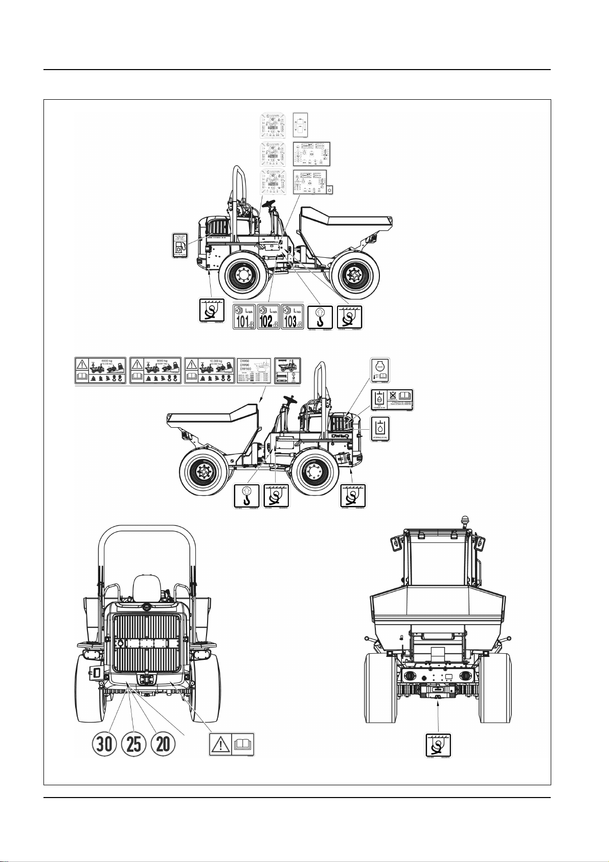
3 Introduction
Fig. 20
Information labels
3-12 BA D18 us* 1.1 * D18e300.fm
Page 51

Meaning
Fig. 21
Fig. 22
Fig. 23
Fig. 24
Fig. 25
Fig. 26
Fuses and relays
Position
Inside the fuse cover.
Meaning
Main fuses and relays
Position
Inside the fuse cover.
Meaning
Machine lifting points
Introduction 3
Position
At the lifting eyes.
Meaning
Machine tie-down points
Position
At the tie-down points.
Meaning
Only refuel with diesel fuel with a sulfur content of less than mg/kg (=als15
0.0015 %) .
Position
Next to the fuel tank filler inlet.
Meaning
The reservoir contains hydraulic oil.
Position
Next to the filler inlet of the hydraulic oil reservoir.
BA D18 us* 1.1 * D18e300.fm 3-13
Page 52

3 Introduction
Information
Fig. 27
Fig. 28 (symbolic representation)
Fig. 29
Fig. 30 (symbolic representation)
Fig. 31 (symbolic representation)
Meaning (option)
The reservoir contains biodegradable hydraulic oil.
This label is notched on the side depending on the biodegradable
hydraulic oil used.
Position
Next to the filler inlet of the hydraulic oil reservoir.
Meaning
Indication of sound power level produced by the mach ine .
L
= sound power level.
Wa
The sound power level depends on the machine.
Position
On the rear frame on the right.
Meaning
This label explains how to lift the machine with a crane.
Position
At the rear of the skip.
Meaning
Indication of maintenance intervals.
Position
On the seat console on the right.
The maintenance labels depend on machine equipment and destination
country.
Meaning
Identifies the design-specific machine speed.
Position
At the rear left of the machine and on the machine frame on the left and
the right.
3-14 BA D18 us* 1.1 * D18e300.fm
Page 53

Meaning
Fig. 32
Fig. 33
Fig. 34
Fig. 35 Symbolic representation
Trailer coupling
Position
On the rear part of the machine on right.
Meaning
Tire pressure
Position
At the rear of the skip.
Meaning
Introduction 3
Thermal stability of coolant.
Position
On the radiator in the engine compartment.
Meaning
This label shows the following information/regulations:
• Maximum payload of machine.
• Tilt out the raised skip only on horizontal ground.
• Tilt out only in straight machine position.
• Maximum slope inclination allowed for tilting out downhill
• Maximum permissible angle of inclination during machine travel across
a slope.
• Do not tilt out the skip if material is stuck in the skip.
Position
At the rear of the skip.
BA D18 us* 1.1 * D18e300.fm 3-15
Page 54

3 Introduction
Fig. 36
ANSI label (option)
3-16 BA D18 us* 1.1 * D18e300.fm
Page 55
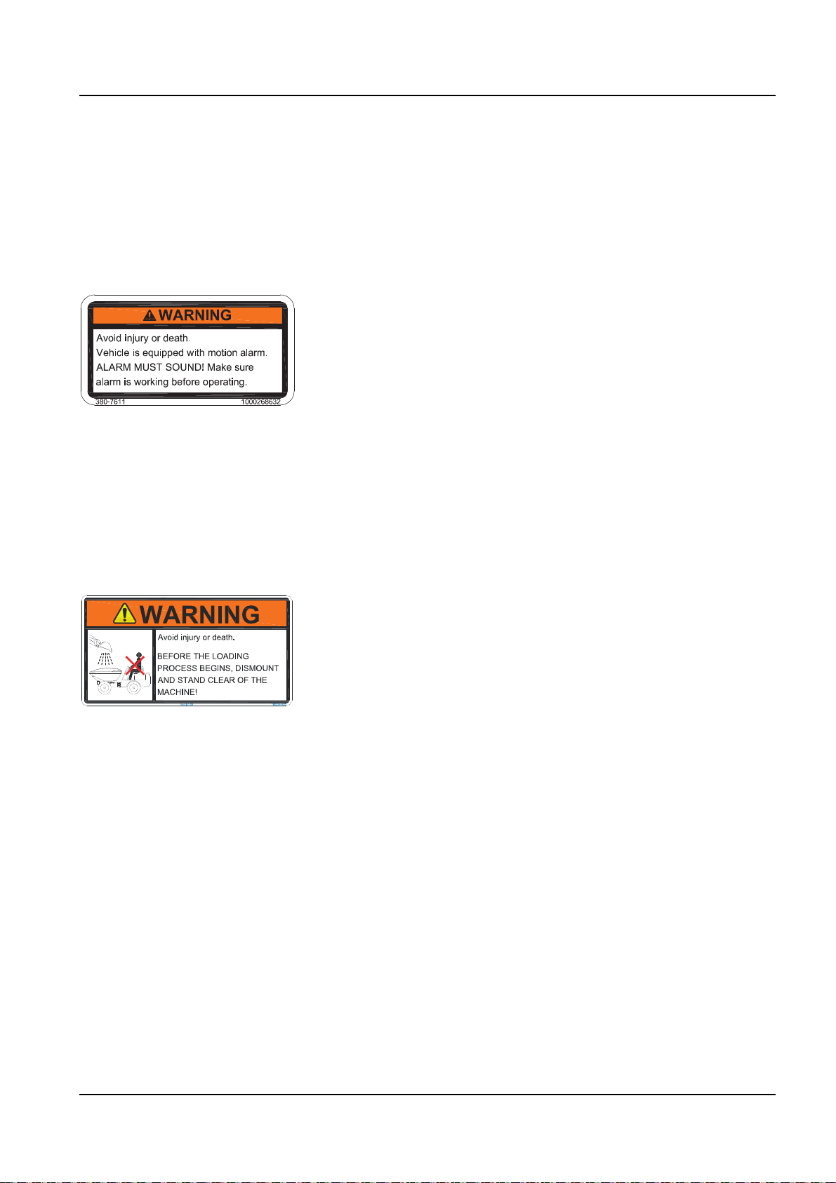
Position
Fig. 37
Fig. 38
Fig. 39
Fig. 40
On the air filter in the engine compartment.
Position
On the B pillar (cabin) or on the ROPS bar on the right.
Position
On the air filter in the engine compartment.
Introduction 3
Position
At the rear of the skip.
BA D18 us* 1.1 * D18e300.fm 3-17
Page 56

3 Introduction
Fig. 41
Fig. 42
Fig. 43
Position
On the battery cover.
Position
On the battery cover.
Position
On the skip on the left and right.
3-18 BA D18 us* 1.1 * D18e300.fm
Page 57

Position
Fig. 44
Fig. 45
On the B pillar on the left.
Position
On the B pillar on the left.
Introduction 3
BA D18 us* 1.1 * D18e300.fm 3-19
Page 58

3 Introduction
Fig. 46
Fig. 47
Fig. 48
Position
On the B pillar on the left.
Position
On the inside of the engine cover.
Position
On the maintenance flap on the left and right.
3-20 BA D18 us* 1.1 * D18e300.fm
Page 59
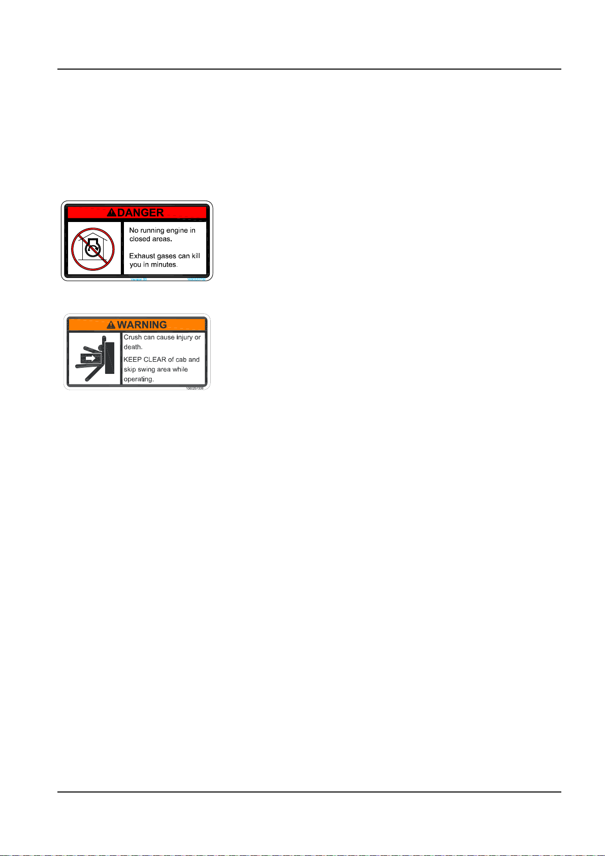
Position
Fig. 49
Fig. 50
Fig. 51
Fig. 52
On the maintenance flap on the left.
Position
On the B pillar (cabin) or on the ROPS bar on the right.
Position
On the machine frame on the left and right.
Introduction 3
Position
On the ROPS bar.
BA D18 us* 1.1 * D18e300.fm 3-21
Page 60

3 Introduction
Notes:
3-22 BA D18 us* 1.1 * D18e300.fm
Page 61

CAUTION
CAUTION
Information
Fig. 53
A
B
Fig. 54
A
B
Putting into operation
4 Putting into operation
4.1 Cabin/control stand
Injury hazard when entering or exiting!
Entering or exiting incorrectly can cause injury.
► Keep the mandatory climbing aids A and handholds B clean and only
use them for entering and exiting.
► Face the machine as you enter and leave it.
► Have damaged climbing aids replaced immediately. Do not operate the
machine.
Putting into operation 4
Crushing hazard due to unlocked cabin door!
Unlocked cabin doors can cause crushing.
► Lock th e ca bin door.
► Use the handholds for closing.
Entry and exit
Use the climbing aids A and handholds B, and do not hold onto the control
elements.
Entry and exit is possible on either side.
Cabin entry and exit (option)
Use climbing aid A and handholds B, and do not hold onto the control
elements.
Entry and exit is possible on either side.
When entering or leaving the cabin, the door must be locked in the
arrester.
BA D18 us* 1.1 * D18i400.fm 4-1
Page 62
4 Putting into operation
Fig. 55
L
R
A
B
Fig. 56
D
C
Fig. 57
E
Unlocking and locking the door (option)
Both cabin doors are equipped with locks.
Unlocking
Turn the starting key in door lock A anticlockwise (L).
Lock
Turn the starting key in door lock A clockwise (R).
Opening the door
Outside
Press door lock A and pull handle B. To keep the door in the open
position, let door arrester C engage in lock D.
Inside
Press lever E on the door lock downward.
4-2 BA D18 us* 1.1 * D18i400.fm
Page 63
Closing the door
Fig. 58
A
B
Fig. 59
A
C
Fig. 60
A
Putting into operation 4
Outside
Release the door from the arrester by pressing ba ll handle A and closing it
with handle B outside until it engages.
Inside
Release the door from the arrester by pressing ball handle A and close it
with handle C until it engages.
Opening the door to a gap
Emergency exit
The door can be opened to a gap during machine operation with the door
arresters at the front left and right in the cabin.
1. Turn door opener A outward.
2. Let the door engage in door arrester A.
➥ The door is opened to a gap during machine operation.
The cabin has doors on the left and right. One side can therefore always
be used as an exit in case of an emergency.
BA D18 us* 1.1 * D18i400.fm 4-3
Page 64
4 Putting into operation
WARNING
WARNING
Information
Fig. 61
Fig. 61
2
A
1
3
Seat adjustment
Accident hazard due to seat adjustment during machine operation!
Adjusting the operator seat during machine operation can cause serious
injury or death.
► Adjust the operator seat before putting the machine into operation.
► Ensure that the levers are locked into place.
Spinal cord injury due to incorrect seat adjustment!
An incorrect weight adjustment can cause injury to the spinal cord.
► Ensure that the seat is correctly adjusted to the operator’s weight
before machine travel or operation.
► Machine operation is prohibited for operators weighing less than 50 kg
(110 lbs) or more than 140 kg (309 lbs).
The operator seat can be fitted with an optional operator presen ce switch.
The traveling drive shifts to neutral as soon as the operator is not seated
for more than 25 seconds.
Functional check of operator presence switch (option)
Perform a functional check once a day.
1. Start the machine.
2. Sit down on the operator seat.
3. Put slide switch A in position 2 or 3 and check whether machine travel
starts.
4. Remove the weight off the operator seat for at least five seconds.
5. Carefully bring slide switch A to position 2 or 3.
➥ The machine must not start moving.
Contact a Wacker Neuson service center immediately if the machine
starts.
4-4 BA D18 us* 1.1 * D18i400.fm
Page 65

Operator seat
Fig. 62
A
B
Fig. 63
C
Fig. 64
D
Putting into operation 4
Adjusting the weight
1. Sit down on the operator seat.
2. Fold out and turn crank A until the red scale is in the middle of
indicating instrument B (on the seat surface).
Adjusting the backrest
1. Sit down on the operator seat.
2. Push handle C in the direction of the arrow and move the backrest to
the required position at the same tiem.
3. Release handle C.
Horizontal adjustment
1. Sit down on the operator seat.
2. Pull handle D upward and at the same time lock the seat in the
required position.
BA D18 us* 1.1 * D18i400.fm 4-5
Page 66

4 Putting into operation
WARNING
WARNING
Retracting seat belt
Injury hazard if the seat belt is not fastened correctly or not at all!
Fastening the seat belt incorrectly, or not at all, can cause serious injury or
death.
► Firmly fasten your seat belt over your hips before starting machine
operation.
► Do not fasten a twisted seat belt, and do not place it over hard, edged
or fragile items in your clothes.
► Ensure that the buckle is inserted (pull test).
► Do not use seat belt extensions.
Injury hazard due to damaged or dirty seat belt!
A damaged or dirty seat belt can cause serious injury or death.
► K ee p th e sea t be lt and bu ckle clean, and check them for damage.
► Have a damaged seat belt and buckle immediately replaced by a
Wacker Neuson service center.
► Have the seat belt immediately replaced after every accident and the
bearing capacity of the fastening points and seat fixtures checked by a
Wacker Neuson service center.
4-6 BA D18 us* 1.1 * D18i400.fm
Page 67

Putting into operation 4
WARNING
WARNING
Fig. 65
A
B
Fig. 66
C
B
D
Fastening the seat belt
Insert buckle latch A into seat belt buckle B until it engages.
Unfastening the seat belt
Press the red push button switch C on seat belt buckle B until the buckle
latch comes out.
➥ Seat belt D is automatically retracted.
Adjusting the mirrors (option)
Injury hazard to persons in the danger zone!
Persons in the danger zone are possibly not seen when reversing the
machine. This can cause accidents with serious injuries or death.
► Adjust the ex istin g visu a l aids (fo r exam p le th e re ar vie w mi rro rs)
correctly.
► Interrupt work immediately if persons enter the danger zone.
► Pay attention to the movements and changing positions of persons.
Accident hazard due to restricted field of vision on the job site!
Accidents resulting in serious injury or death can be caused by a restricted
field of vision.
► Do not allow anyone to stay in the danger zone.
► Use suitable visual aids if necessary (for example a camera, mirrors,
guide).
► Additional equipment must not be installed if it impairs visibility.
BA D18 us* 1.1 * D18i400.fm 4-7
Page 68

4 Putting into operation
WARNING
Fig. 67
Fig. 68
Accident hazard due to incorrect adjustment of visual aids!
Incorrectly adjusted visual aids can cause serious injury or death.
► Before starting work, ensure that all visual aids are clean, functional and
adjusted in accordance with the instructions in this Operator’s Manual.
► Immediately replace damaged or broken visual aids.
► Curved mirrors enlarge, reduce or distort the field of view.
► The operator must follow the national and regional regulations.
• Use safety-oriented ladders and work platforms for adjustment work on
the machine.
• Do not use machine components as a climbing aid.
• Set the skip to travel position before adjusting the mirrors.
Adjusting the outside rearview mirrors on left and right
• Ensure sufficient visibility from the operator seat onto the job site.
• Ensure maximum visibility to the rear.
• Ensure visibility of the rear left edge of the machine in the mirror on the left.
• Ensure visibility of the rear right edge of the machine in the mirror on
the right.
Adjusting the inside mirror
• Ensure sufficient visibility from the operator seat onto the job site.
4-8 BA D18 us* 1.1 * D18i400.fm
Page 69

Camera (option)
Information
Fig. 69
2
3
1
5
4
Fig. 70
Putting into operation 4
The camera display is protected with a transparent flap. Raise the flap to
operate the display.
1. ON/OFF switch
2. SEL
For selecting pages in the menu.
3. Menu
For activating the menu. The menu list is hidden after seven seconds if
no selection is made.
4. Buttons
For modifying a value.
5. Day/night sensor
Automatic brightness adjustment
Setting the display
The following settings can be made:
• Brightness
• Contrast
•Color
•Color
1. Press the Menu button.
2. Select the required setting with the buttons.
3. Press the SEL button.
4. Select the required setting with the buttons.
5. Confirm with the SEL button.
6. Press the menu button to exit the settings menu.
Setup menu – adjusting the camera
The camera is preset at the factory. For additional details contact a
Wacker Neuson service center.
Visual range
The camera has a vertical visual range of 66°.
The camera has a horizontal visual range of 88°.
The camera’s field of vision is restricted if the skip is tilted.
BA D18 us* 1.1 * D18i400.fm 4-9
Page 70

4 Putting into operation
Information
Fig. 71
Fire extinguisher
A fire extinguisher is not available from Wacker Neuson.
Contact a Wacker Neuson service center for the installation of a fire
extinguisher (NFPA).
Ensure that the fire extinguisher is firmly fastened during machine
operation. Inspect the holder and the fire extinguisher regularly. Observe
the manufacturer’s indications.
4-10 BA D18 us* 1.1 * D18i400.fm
Page 71

Protective structures
DANGER
Information
Putting into operation 4
Protective structures are additional elements that protect the operator
against hazards. These elements can be installed later on or as standard
equipment.
Accident hazard due to modified cabin or protective structures!
Modifications (for example drilling) weaken the structure and causes
serious injury or death.
► No drilling, cutting or grinding.
► Do not install any brackets.
► No welding, straightening or bending.
► Replace the complete protective structure if it is damaged, deformed or
cracked.
► Contact a Wacker Neuson service center in case of doubt.
► Retrofit, assembly and repair work may only be performed by a
Wacker Neuson service center.
► Replace self-locking fasteners.
► Screws to which an adhesive has been applied must be cleaned with a
suitable cleanser before they are re-used.
Machine operation is only allowed with a correctly installed and intact
rollbar or correctly installed and intact cabin.
For additional protection, only use correct ly insta lle d an d int ac t Wack er
Neuson protective structures that have been released for the machine.
Responsibility for machine equipped with protective structures
The decision regarding the necessary protective structures (type and
level I or II) must be made by the company/person operating the machine
and depends on the specific work situation.
The operating company of the machine mu st obse r ve th e na tio na l
regulations and he must inform the operator on the protective structure to
be used in a specific work situation.
BA D18 us* 1.1 * D18i400.fm 4-11
Page 72

4 Putting into operation
DANGER
Information
FOPS level II cabin (option)
Crushing hazard due to falling objects!
Causes serious injury or death.
► Install a protective FOPS structure in areas with danger of falling
objects.
The cabin complies with the FOPS level II requirements according to EN
ISO 3449:2008
► The machine owner must ensure that the hazard situation is evaluated
and that the national regulations are observed.
► The machine owner must ensure that only work is performed that does
not require any higher protection.
► Accidents cannot be fully avoided despite equipping a machine with
protective structures.
4-12 BA D18 us* 1.1 * D18i400.fm
Page 73

Rollbar
DANGER
DANGER
Information
Fig. 72
A
Putting into operation 4
Rollbar A is included in the machine’s standard equipment.
Accident hazard due to falling objects!
Causes serious injury or death.
► Machine operation is only allowed if the rollbar is raised and locked,
and if the seat belt is fastened.
► Wear protective equipment (for example protective clothing, safety
glasses).
► Operation in areas involving a risk of falling objects is prohibited.
► Operation in areas with fragments flying around is prohibited.
Machine travel with a lowered rollbar
In case of a low clearance height, the rollbar can be lowered if machine
travel is limited to a short distance through a passage.
Accident hazard during machine operation with a lowered rollbar!
Can cause serious injury or death.
► Perform machine travel only on absolutely level ground.
► Do not fasten the seat belt in order to be able to leave the machine
immediately in an emergency.
► Wear protective equipment (for example protective clothing, safety
glasses).
However, the following conditions must be fulfilled:
• Ob ta i n th e ap pr o val of the appropriate national authority.
• Working with a lowered rollbar is prohibited under all circumstances.
• The machine must make no tipping movement.
The rollbar weight is about 100 kg (220 lb) depending on the model. A gas
strut is installed to support raising and lowering. However, inspite of the
rollbar being equipped with a gas strut, only lower it with two qualified
persons from the side of the machine.
BA D18 us* 1.1 * D18i400.fm 4-13
Page 74
4 Putting into operation
Information
Fig. 73
B
C
D
Fig. 74 Sunshield
A
Fig. 75 Sunshield
A
Sun visor (option)
Lowering the rollbar
1. Park the machine on level ground.
2. Raise ring D.
3. Remove split pin C from lock pin B.
4. Remove lock pin B.
5. Slowly lower rollbar A with the help of a second qualified person from
the side of the machine.
Raising the rollbar
1. Park the machine on level ground.
2. Raise the rollbar with the help of a second qualified person.
3. Secure the rollbar with lock pins B.
4. Secure lock pins B with split pins C.
5. Lower ring D.
The sun visor can increase road safety. It is located at the upper edge of
the cabin. Fold down the sun visor as required. Adjust the sun visor so
that the machine travel and operating range is not covered.
Sunshield (option)
Sunshield A protects against excessive sun.
Do not remove protection B if a sunshield is installed. It prevents the
sunshield from hitting the engine cover when the rollbar is lowered.
4-14 BA D18 us* 1.1 * D18i400.fm
Page 75
Putting into operation 4
Fig. 76
B
Fig. 77
C
F
Fig. 78
E
D
Protection (on left and right of rollbar).
Assembly:
Install the sunshield with at least two qualified persons.
1. Remove the rotating beacon.
2. Route the cable for the rotating beacon through the opening in the roof.
3. Insert the assembly brackets D through the openings in the roof and
tighten screws E to 87 Nm (64 ft.lbs).
4. Insert extensions C through the openings in the roof and tighten them
to 130 Nm (96 ft.lbs) on the rollbar.
5. Tighten bracket F on extension C.
6. Install the rotating beacon.
BA D18 us* 1.1 * D18i400.fm 4-15
Page 76

4 Putting into operation
Fig. 79 Symbolic representation
A
Fig. 80
B
Fig. 81
Fig. 82
Skip grid (option)
Skip grid A protects the cabin and the operator’s compartment against
falling material or against an excavator bucket penetrating the cabin
during loading.
Assembly:
Skips delivered from quarter 4/2015 have a threaded fitting for fastening
the skip grid with screws.
1. Stop and park the machine. Stop the engine – see “Preparing
lubrication” on page 7-8.
2. Put the skip grid on the assembly points with at least two persons. Use
suitable external climbing aids.
3. Tighten the four screws B to 410 Nm (302 ft.lbs).
Lowering/raising the skip grid
The skip grid must be lowered during machine travel on public roads.
1. Steer the machine as shown in Fig. 82. Stop the engine.
2. Remove split pin C from pin D on the side with the smaller an g l e.
3. Remove it from the hole
4. Lower the grid.
5. Insert pins D in the holes and secu re them with split pin C.
6. Steer the machine to the other side.
7. Perform steps 2 to 5 on the side with the smaller angle.
4-16 BA D18 us* 1.1 * D18i400.fm
Page 77

Document box
Fig. 83
C
D
2
1
Fig. 84
A
12 V connection
Putting into operation 4
Function Position
Raise Insert and secure the pin in hole 1
Lower Insert and secure the pin in hole 2
The Operator’s Manual is stored in the document box under the seat.
A 12 V power outlet A is located beside the starter.
4.2 Overview of control elements
This chapter describes the controls, and contains information on the
function and handling of the indicator lights and controls.
The pages stated in the table refer to the description of the controls.
BA D18 us* 1.1 * D18i400.fm 4-17
Page 78
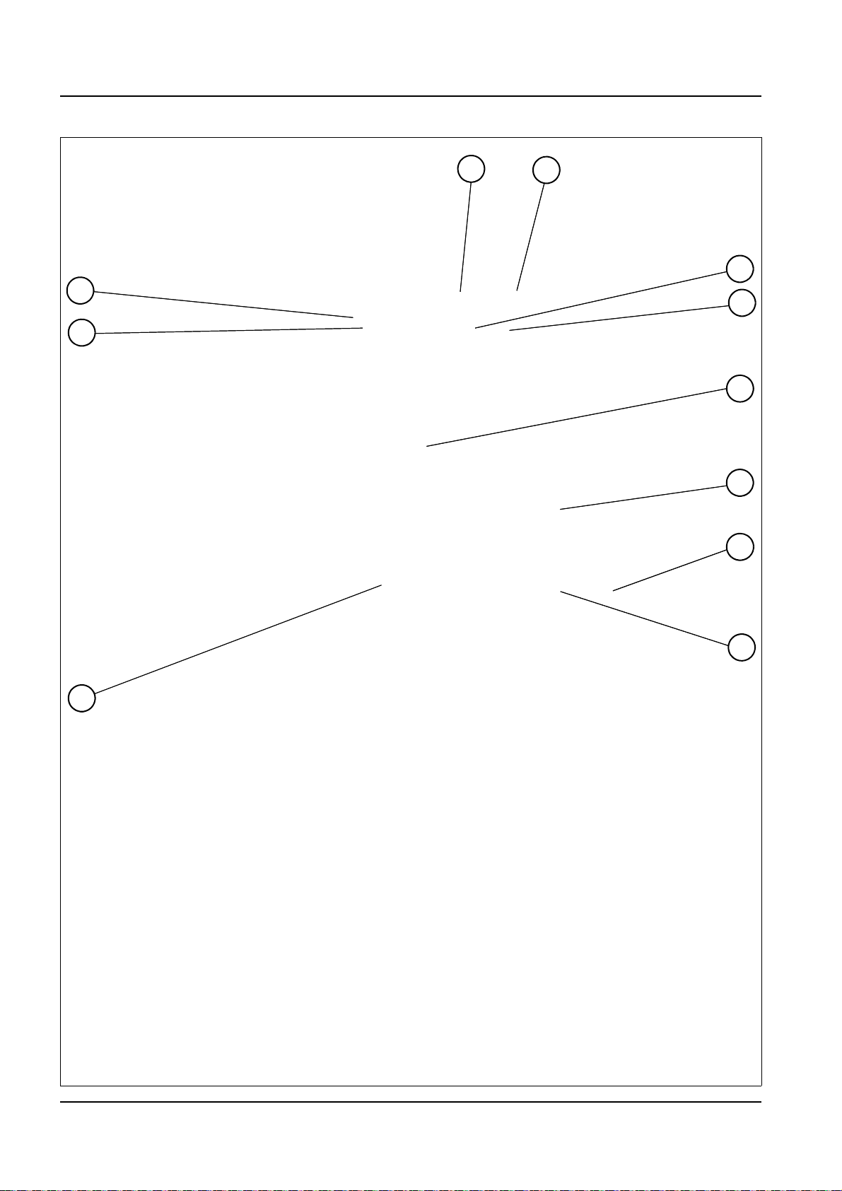
4 Putting into operation
Fig. 85 Overview of control elements
4
5
6
1
2
9
10
3
11
8
7
Control stand
4-18 BA D18 us* 1.1 * D18i400.fm
Page 79

Putting into operation 4
Designation See page
1 Operator seat and seat belt
2 Service brake
3 Steering-column lever (option for Austrian road traffic regulations StVZO)
4 Display elemen t
5 Switch panel
6 Accelerator pedal
7 12 V connection
8 Document box
9 Control lever
10 Ope ratin g hy dr au lics loc k lever
11 Parking brake
4-4; 4-6
5-4
4-22
4-24
4-22
5-3
4-17
4-17
5-3
5-10
5-4
BA D18 us* 1.1 * D18i400.fm 4-19
Page 80

4 Putting into operation
Fig. 86 Overview of control elements
7
15
8
9
1
5
12
13
6
14
3
4
16
17
11
2
10
Cabin (option)
4-20 BA D18 us* 1.1 * D18i400.fm
Page 81

Putting into operation 4
Designation See page
1 Operator seat and seat belt
2 Rear left switch panel (option)
3 Drinks holder
4 Switch panel on left (option)
5 Service brake
6 Steering-column lever (option for Austrian road traffic regulations StVZO)
7 Display elemen t
8 Switch panel
9 Accelerator pedal
10 12 V connection
11 Document box
12 Control lever
13 Ope ratin g hy dr au lics loc k lever
14 Parking brake
15 Washer fluid reservoir (cabin option)
16 Temperature controller (cabin option)
17 Radio (option)
4-4; 4-6
4-22
--
4-22
5-4
4-22
4-24
4-22
5-3
4-17
4-17
5-3
5-10
5-4
5-20
5-21
--
BA D18 us* 1.1 * D18i400.fm 4-21
Page 82
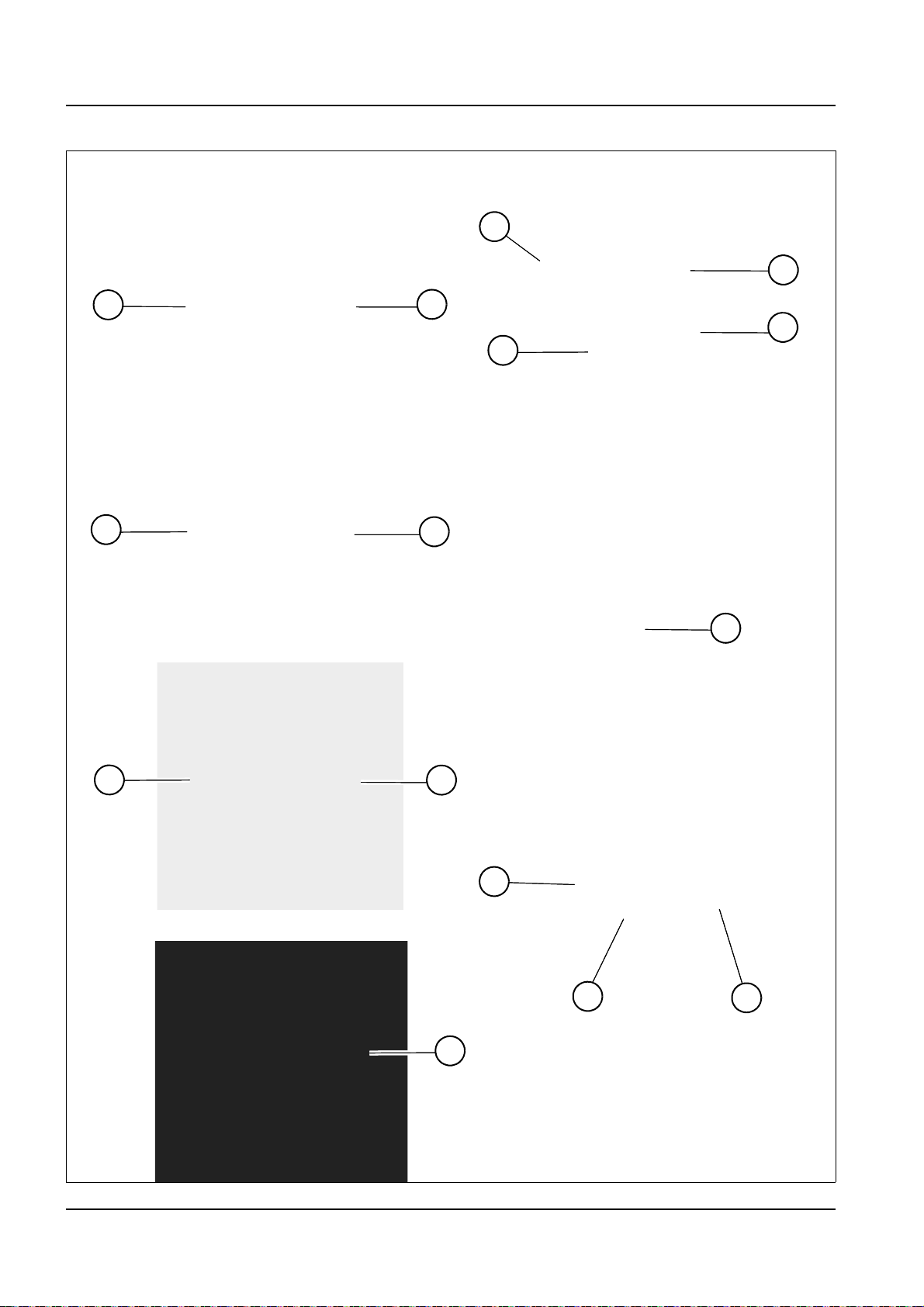
4 Putting into operation
Fig. 87
Switch panel on left (option)
Switch panel
2
10
8
Rear left switch panel (option)
1
3
4
12
11
6
7
Front side of control lever
9
Steering-column lever (option)
Rear side of control lever
13
14
15
5
Control elements and switches
4-22 BA D18 us* 1.1 * D18i400.fm
Page 83

Putting into operation 4
Designation See page
1 Hazard warning system (option)
2 Rotating beacon (option)
3 Working lights (option)
4 Particulate matter catalyst (Tier IV engine only)
5 Operating hydraulics
6 Selection of travel direction
7 Eco push button
8 Speed changeover (no function for DW 60)
9Horn
10 Ventilation (option)
11 Air conditioning (option)
12 Wiper/wa sh system (option)
13 Horn (option)
14 Road travel lights (option)
15 Turn indicators (option)
5-19
5-18
5-16
7-42
5-22
5-11
5-3
5-3
5-18
5-21
5-21
5-20
5-18
5-17
5-19
BA D18 us* 1.1 * D18i400.fm 4-23
Page 84

4 Putting into operation
Information
5
8
4
9
1
6
2
3
7
10
11
12
16
13
14
15
17 18
4.3 Indicator lights and warning lights (overview)
Display element
The display element and the multifunctional display informs the operator
of the operating states, required maintenance or possible machine
malfunctions.
After switching on the starter, the indicator lights are checked during the
first 2 seconds and the current reading of the maintenance meter is
displayed. Then the operating hours are automatically displaye d.
4-24 BA D18 us* 1.1 * D18i400.fm
Page 85

Putting into operation 4
No. Symbol Color Designation See
1
2
3
4
5
6
7
8
9
Green
Yellow
Yellow
Red
Yellow
Yellow
Red
Yellow
Red
Turn indicators
Flashes when the steering-colum lever is actuated
PCM regeneration disabled/interrupted
High exhaust-gas temperatures
Engine stop
Engine warning
PCM regeneration
Engine oil pressure
Preheating
Charge indicator light
5-19
7-42
7-42
8-1, 8-2,
7-48
8-1, 8-2,
7-48
7-42
8-2
4-35
8-2
10
11
12
13
14
15
16
17
18
Red
Red
Red
Red
Red
Blue
---
---
---
Parking brake
Coolant temperature
General malfunction
(not assigned)
(not assigned)
High beam (Austrian road traffic regulation StVZO option)
Selector button (multifunctional display)
To next menu page/set (multifunctional display)
Multifunctional display
5-4
8-2
8-4
8-2
--
--
--
5-7
5-7
5-3,
5-6,8-2,
8-4
BA D18 us* 1.1 * D18i400.fm 4-25
Page 86

4 Putting into operation
450.2
49.8
12:10
800 rpm
3
4
1
2
1
4
100°
80°
60°
!
35 °C
n/min
800 rpm
Meaning of displays and symbols
Symbol Designation Page
Speed range 1
Speed range 2 (DW90/100 only)
Hour meter
Operating hours to next maintenance
Time
Engine speed
5-3
4-28
5-7
Fuel tank capacity 4-28
Coolant temperature 8-2; 8-4
Engine error
8-6
Machine error
Engine data --
Machine data --
Particulate matter catalyst (without exclam a tio n ma rk from sof twa re
version 3.3)
7-42; 8-6
No malfunction --
Detailed coolant temperatur --
Detailed engine speed --
4-26 BA D18 us* 1.1 * D18i400.fm
Page 87

Putting into operation 4
n/min
Symbol Designation Page
0 kPa
Detailed engine oil pressure --
Engine number
Setting of display brightness
Setting of display contrast
5-7
Setting of time/date
Pilot control pressure
Replace the hydraulic oil filter
Dirty air filter
8-2
--
Dirty hydraulic oil radiator
Charge indicator light
PCM: low load
PCM: medium load
PCM: highest load
Symbol flashes: PCM regeneration required
Symbol illuminates: PCM regeneration active
7-42
BA D18 us* 1.1 * D18i400.fm 4-27
Page 88

4 Putting into operation
Information
Fig. 88
Fig. 89
Fig. 90
Fig. 91
Hour meter
Counts the engine operating hours with the engine running.
Maintenance meter
Counts the engine operating hours until the next maintenance.
The maintenance meter starts at 500.0 hours. It counts down to 0.0 ho urs.
The wrench symbol then starts to flash.
The maintenance meter keeps on counting down (−0.1 hours, −0.2 hours, etc.)
After 500 operating hours the output of the Tier IV diesel engine is
reduced by 25 % if maintenance is not performed.
Fuel level indicator
Indicates the remaining amount of fuel in the tank.
Refuel if the segments reach the low range.
Add fuel if the highlighted symbol appears in the main menu.
4-28 BA D18 us* 1.1 * D18i400.fm
Page 89

Putting into operation 4
4.4 Preparatory work
Important information before putting the machine into operation
Perform a visual check before starting work:
- There must be no leaks.
- There must be no damaged or loose parts.
- Do not allow anyone to stay in the danger zone.
Before putting the machine into operation, the operator must familiarize
himself with the position of the controls and instruments.
Only operate the machine from the seat with the seat belt fastened.
Before using the machine in work operation for the first time, Wacker Neuson
recommends trying out the machine on open ground without any obstacles.
When using the machine, check the surroundings constantly in order to
identify potential hazards in time.
Before starting work or when changing operators, ensure that all visual
aids (for example the mirrors) work correctly, that they are clean and
adjusted in accordance with the instructions in this Operator’s Manual.
The operator must follow the national and regional regulations.
Do not make any modifications that impair visibility. The machine does not
meet the requirements for conformity and registration.
Follow the safety instructions in the safety chapter – see chapter “2.4
General Conduct and Safety Instructions for Operator‘s and Service
Personal” on page 2-2.
BA D18 us* 1.1 * D18i400.fm 4-29
Page 90

4 Putting into operation
Requirements and information for the operating personnel
Read, understand and follow this Operator’s Manual and all other
Operator’s Manuals supplied with the machine.
The machine may only be put into operation by authorized personnel that
has been instructed – see chapter “2.7 Staff Qualifications and Basic
Responsibilities” on page 2-9.
The operator must know and bear in mind the requirements and risks at
the work place.
Perform daily maintenance according to the lubrication and maintenance
plan – see chapter “7.2 Maintenance overview” on page 7-2.
Face the machine as you enter and exit it, and only use the man da to ry
climbing aids for entering and exiting.
Keep the footholds and the handholds clean to ensure a safe hold at all
times. Immediately remove dirt, oil, snow, etc .
Always use the mandatory climbing aids when entering and exiting the
machine.
Do not get on a moving machine, or jump off it.
Do not operate the machine if the standard protective equipment (for
example the cabin) has been removed.
Watch the material as you tilt out the skip. Material stuck in the skip can
cause a tipping hazard. Remove stuck or frozen material from the skip
with a suitable tool.
No parts of the body or clothes may protrude outside the machine during
operation.
4-30 BA D18 us* 1.1 * D18i400.fm
Page 91

Check lists
Putting into operation 4
The checklists below assist you in checking and monitoring the machine
before, during and after operation.
Wacker Neuson does not claim those lists to be exhaustive.
If the answer to one of the following questions is No, first rectify the cause
of the error (or have it rectified) before starting or continuing work.
The checking and monitoring work listed below is described in greater
detail in the following chapters.
Start-up checklist
Check and observe the following points before putting the machine into
operation or starting the engine:
No. Question Page
1
2
3
4
5
6
7
8
9
10
Enough fuel in the tank? 7-20
Correct engine oil level? 7-26
Coolant level OK? 7-28
Hydraulic oil level correct? 7-33
Correct brake fluid level? 7-39
Glass cleaner in washer reservoir OK? 7-39
Lubrication points greased? 7-9
Tires checked for cracks, cuts, etc. ? 7-40
Light system, signaling, warning and indicator lights
operational?
Windows, mirrors, lights, steps, all pedals and cont rol
levers clean and correctly adjusted?
--
-11
12
13
14
15
16
All control levers and pedals in neutral position? 5-11
Maintenance flaps on left und right locked?
Filler cap locked?
Especially after cleaning, maintenance or repair work:
Rags, tools and other loose objects removed?
Seating position adjusted correctly? 4-4
Seat belt fastened? 4-6
Before putting the machine into operation, ensure that
nobody is in the danger zone.
7-13
--
5-24
BA D18 us* 1.1 * D18i400.fm 4-31
Page 92

4 Putting into operation
Operation checklist
Check/observe the following before beginning operation or after starting
the engine:
No. Question Page
Are there any persons or objects in the dange r zon e of
1
the machine?
5-24
Indicator light for engine oil pressure and alternator
2
charge function gone out after a few seconds?
Has a brake test been performed? 5-5
3
Coolant temperature of engine in normal range?
4
Indicator lights for hydraulic oil filter and air filter do not
5
illuminate?
Does the control lever work correctly? 5-22
6
Parking checklist
Check and observe the following points when parkin g the ma ch ine :
No. Question Page
Skip lowered? 5-15
1
Cabin locked, especially if the machine cannot be super-
2
vised?
Parking brake applied? 5-4
3
When parking on public roads:
Machine appropriately secured?
Machine additionally secured with chocks under the
4
wheels to prevent it from rolling away?
When parking on slopes:
8-2
8-2
8-4
8-2
4-2
5-15
Machine additionally secured with chocks under the
5
wheels to prevent it from rolling away?
4-32 BA D18 us* 1.1 * D18i400.fm
5-15
Page 93
Putting into operation 4
Information
Fig. 92
A
B
Putting into operation for the first time and running-in period
Before putting the machine into operation for the fir st tim e, check wh ether
the equipment supplied with the machine is complete.
• Check the fluid levels according to chapter “Maintenance”.
Each machine is correctly adjusted and checked before it is delivered.
Handle the machine carefully during its first 50 operating hours.
• Do not loa d a cold engin e .
• Warm up the machine at low engine speed and little load, do not warm
it up at a standstill.
• Do not change engine speed abruptly.
• Avoid using the machine under heavy loads or at high speeds.
• Avoid abrupt acceleration, braking and changing travel direction.
• Do not run the engine at high speed for extended periods.
• Observe the maintenance plans – see chapter “7.2 Maintenance
overview” on page 7-2.
Equipment for Austrian road traffic regulations StVZO (option)
Observe the national and regional regulations during machine travel on
public roads.
Scope of delivery of option Equipment for Austrian road traffic
regulations StVZO:
• Headlights and rear lights
• Turn indicators and clearance lights
• Rotating beacon
• Horn on steering-column lever
• Outside rearview mirrors on left and right
• Numberplate bracket and lights
• Wheel chock
The rear light unit A can be folded in for protection during machine
operation on non-public sites.
1. Remove lock pin B from the lock.
2. Fold the rear light unit A unde r the pr ot ec tion.
3. Insert lock pin B back into the lock.
BA D18 us* 1.1 * D18i400.fm 4-33
Page 94

4 Putting into operation
WARNING
Information
Information
Fig. 93
Machine travel on public roads
1. Ensure that all legal requirements for machine travel on public roads
are fulfilled. This applies both to the machine and to the operator (for
example a corresponding driving license).
2. Lower the skip completely. If the machine is equipped with a swivel
skip, ensure in addition that the skip is in the middle position.
3. Lock the control lever – see “Enabling/disabling the operating
hydraulics” on page 5-10.
4.5 Starting and stopping the engine
Preparations for starting the engine
Accident hazard due to unintentional operation of the machine!
Unintentional operation can cause serious injury or death.
► Only operate the machine from the seat with the seat belt fastened.
The starter cannot be actuated if the engine is already running (start
repeat interlock).
Do not run the starter for more than 30 seconds.
Wait two minutes so the battery can recover and the starter does not
overheat before trying again.
Ensure sufficient ventilation during operation in enclosed premises.
All controls must be within easy reach.
4-34 BA D18 us* 1.1 * D18i400.fm
Page 95
Starter
Fig. 94
0
1
2
3
P
Fig. 95
0
1
2
3
P
Fig. 96
A BC
Putting into operation 4
Position Function
Starting the engine
P Park position
Insert or remove the starting key
0 Stop position
1 Position for accessories All elec tric functions are enabled
2 Preheats the engine Preheater active
3 Starts the engine Starter is actuated
1. Switch off all electric consumers.
2. Insert the starting key.
3. Turn the starting key to position 1.
4. All indicator lights illuminate for two seconds.
➥ Have malfunctioning indicator lights immediately replaced.
5. Turn and hold the starting key in position 2 until indicator light A
(preheating) goes out.
➥ Indicator light B (alternator charge) illuminates.
➥ Indicator light C (engine oil pressure) illuminates.
6. Turn and hold the starting key in position 3 until the engine starts.
➥ Release the starting key.
➥ All indicator lights go out.
If the engine does not start after 30 seconds:
Interrupt the start procedure and repeat it after two minutes.
If the engine still does not start after a few tries, contact a Wacker Neuson
service center.
Warm-up phase
After starting the engine, let it warm up at slightly increased idling speed
until it reaches its operating temperature.
Check for unusual noise, exhaust color, leaks, malfunctions or damage.
In case of malfunctions, damage or leaks:
Secure the machine, park it and find out the cause for the damage and
have it repaired.
BA D18 us* 1.1 * D18i400.fm 4-35
Page 96

4 Putting into operation
WARNING
Starting the engine at low ambient temperatures
Start the engine as described in chapter Starting the engine.
Warm-up phase at low ambient temperatures
• Let the engine run below 1800 rpm until the coolant reaches its
operating temperature.
• Avoid fast movements of the operating hydraulics.
• Check for unusual noise, exhaust color, leaks, malfunctions or
damage.
In case of malfunctions, damage or leaks:
Secure the machine, park it and find out the cause for the damage and
have it repaired.
Notices on the warm-up phase
• After reaching the operating temperature, the engine can be operated
under full load.
• The engine reaches its operating temperature more quickly at low
engine speed and under load. This is more efficient than operation at
low engine speed without any load.
• Avoid excess idling. This causes carbon deposits or an increased soot
load of the particulate matter catalyst, for example.
Crushing hazard during operation with cold hydraulic oil!
Cold hydraulic oil can cause uncontrolled machine movements. This can
cause serious injury or death.
► The hydraulic oil is still cold even if the engine has reached its
operating temperature.
► If possible, run the machine warm on wide and open terrain.
► Op er at e th e con tr ol lev er esp ecially ca refully if the hydraulic oil is cold.
4-36 BA D18 us* 1.1 * D18i400.fm
Page 97

Starting aid
WARNING
WARNING
WARNING
NOTICE
NOTICE
NOTICE
Putting into operation 4
Explosion hazard in case of incorrect handling of battery!
Incorrect battery handling can cause serious injury or death.
► Wear protective equipment.
► Fire, open flames and smoking is prohibited.
► Do not jump start the engine if the battery is malfunctioning or frozen,
or if the acid level is too low.
Burn hazard due to hot surfaces!
Can cause serious burns or death.
► Stop the engine and let it cool down.
► Wear protective equipment.
Injury hazard due to rotating parts!
Rotating parts can cause serious injury or death.
► Open the maintenance flap only at engine standstill.
Damage to machine due to electrical short-circuit or overvoltage.
► Do not bring the positive terminal of the starting battery into contact
with electrically conductive vehicle parts.
► The vehicles must not touch each other during the starting aid.
► If the engine still does not start despite a starting aid, contact a Wacker
Neuson service center.
Possible damage due to wrong battery voltage.
► Only use batteries with the same voltage (12 V).
Possible damage to machine with empty battery due to voltage peaks.
BA D18 us* 1.1 * D18i400.fm 4-37
Page 98

4 Putting into operation
NOTICE
Information
Fig. 97
Fig. 97
A
B
Damage to battery jumper cables when placing them near rotating parts.
Use only authorized battery jumper cables which conform to national and
regional safety requirements.
Designations/symbols Meaning
X Machine with empty battery
Y Vehicle with full battery
C Positive/machine X
D Positive/vehicle Y
E Negative/vehicle Y
F Negative/machine X
Full battery
Connections
1. Move vehicle Y close to machine X so that the length of the battery
jumper cables is sufficient.
2. Let the engine of vehicle Y run.
3. Remove rubber mat A.
4. Remove screws B.
5. Remove the base cover.
4-38 BA D18 us* 1.1 * D18i400.fm
Page 99

Putting into operation 4
WARNING
Fig. 98 (symbolic representation)
Starting
battery
F
C
D
E
6. Open the engine cover.
7. Connect the battery jumper cables in the following order: C-D-E-F.
8. Wait five minutes for the empty battery to be charged a little.
Injury hazard due to open base cover!
Can cause serious injury and death.
► Ensure a secure footing when you get on the machine with the base
cover open.
9. Start the engine of machine X.
10.Disconnect the battery jumper cables in the following order: F-E-D-C.
11.Install the base cover again and secure it with the screws.
12.Fit rubber mat A.
BA D18 us* 1.1 * D18i400.fm 4-39
Page 100

4 Putting into operation
NOTICE
NOTICE
Information
Fig. 99
0
1
2
3
P
Low-load operation
Stopping the engine
Possible damage to the engine due to low-load operation.
► Run the engine at idling speed or at high engine speed at over 20 %
engine load.
Possible consequences of low-load operation are:
• Increased engine oil consumption
• Engine contamination due to engine oil in exhaust system
• Blue smoke in exhaust gas
• Shorter particulate matter catalyst regeneration cycles (only in case of
Tier IV)
• Reduced engine-oil replacement intervals
Possible damage to the engine when it is stopped after runn ing under high
load.
► Letting the engine run at idling speed before stopping it avoids engine
damage and increases the engine’s service life.
1. Let the engine run at idling speed for five minutes without any load.
2. Turn the starting key to “0” and remove it.
After stopping the engine, wait two minutes before disconnecting the
battery or actuating the battery master switch to avoid damage to the
control electronics.
4-40 BA D18 us* 1.1 * D18i400.fm
 Loading...