

Page 1

0114079 010
0900
Rammer
Stampfer
Apisonador
Pilonneuse
DS720
OPERATOR’S MANUAL / PARTS BOOK
BETRIEBSANLEITUNG / ERSATZTEILE
MANUAL DE OPERACIÓN / LISTA DE REPUESTOS
NOTICE D’EMPLOI / LISTE DE PIÈCES DE RECHANGE
0114079
Page 2

BELGIEBELGIE
BELGIE
BELGIEBELGIE
1730 ASSE-MOLLEM1730 ASSE-MOLLEM
1730 ASSE-MOLLEM ASSESTEENWEG 17
1730 ASSE-MOLLEM1730 ASSE-MOLLEM
4040 Herstal 4 Avenue
9800 Deinze Kortrijkse Steenweg 400 Tel. (09)-386 8529
6041 Gosselies-Charleroi Route Nationale Cinq Tel. 071-372450
REPUBLIKA REPUBLIKA
ÇESKÁ
REPUBLIKA
REPUBLIKA REPUBLIKA
19402 PRAHA 9-HLOUBETIN KOLBENOVA 259
DANMARKDANMARK
DANMARK
DANMARKDANMARK
2690 KARLSLUNDE RØRGANGEN 6
8200 Arhus N Randersvej 346 Tel. 86-231777
5250 Odense SV Holkebjergvej 56A Tel. 66-172170
ESPAÑAESPAÑA
ESPAÑA
ESPAÑAESPAÑA
28850 TORREJON DE ARDOZ (MADRID) POLIGONO INDUSTRIAL LAS MONJAS
08780 PALLEJA (Barcelona) PRAT DE LA RIBA, 184 Tel. (93)-6632273
41700 Dos Hermanas (Sevilla) Poligono Industrial La Palmera Tel. (95)-4691129
46133 Meliana (Valencia) Calle Salvador Giner, 6 Tel. (96)-1492102
15890 Santiago de Compostela (La Coruña) Poligono Industrial el Tambre, Via Pasteur, 47a Tel. (981) 573366 / 67
SUOMISUOMI
SUOMI
SUOMISUOMI
04250 KERAVA PAJAPELLONKUJA 4
FRANCEFRANCE
FRANCE
FRANCEFRANCE
77170 BRIE COMTE ROBERT 335, RUE GLORIETTE—ZAC DU TUBOEUF
Aix en Provence 13540 Puyricard Tel. 4 42630526
Arras 62217 Beaurains Tel. 3 21235361
Bordeaux 33700 Merignac Tel. 5 56343346
Bourges 18390 St. Germain du Puy Tel. 2 48652015
Lyon 69740 Genas Tel. 4 78401384
Nancy 54180 Heillecourt Tel. 3 83565801
Rennes 35510 Cesson Sevigne Tel. 2 99321522
Toulouse 31270 Cugnaux Tel. 5 61075250
Kehl 77694 Kehl-Goldscheuer Tel. (0590) 9321
HUNGARIAHUNGARIA
HUNGARIA
HUNGARIAHUNGARIA
1106 BUDAPEST Kada u. 137
IRELANDIRELAND
IRELAND
IRELANDIRELAND
DUBLIN 13 127A. BALDOYLE INDUSTRIAL ESTATE
ITALIAITALIA
ITALIA
ITALIAITALIA
40016 SAN GIORGIO DI PIANO (Bologna) Via Due Agosto, 1980, Strage di Bologna, 3
00125 ACILIA (Roma) Viale Enrico Ortolani, 262 Tel. 39 . 06 . 5219246
20041 Agrate Brianza (Mi) Via Archimede, 31 Tel. 39. 039.699 0136
NEDERLANDNEDERLAND
NEDERLAND
NEDERLANDNEDERLAND
3821 BJ AMERSFOORT COBOLWEG 1
2984 BL Ridderker Glasblazerstraat 7 Tel. 0180 - 41 70 56
7418 EZ Deventer Arnbergstraat 9 Tel. 0570 - 63 00 87
5684 PS Best De Dintel 37 Tel. 0499 - 33 04 33
1704 RT Heerhugowaard Einsteinstraat 4d Tel. 072 - 574 20 78
9411 XN Beilen De Hanekampen 19 Tel. 0593 - 52 31 24
NORGENORGE
NORGE
NORGENORGE
1481 HAGAN TYRIVN. 7
POLSKAPOLSKA
POLSKA
POLSKAPOLSKA
05-850 O•ARÓW MAZOWIECKI UL. KONOTOPSKA 4
62-081 Wysogotowo k. Poznania ul. Kamienna 1 Tel. (061) 814-3797
PORTUGALPORTUGAL
PORTUGAL
PORTUGALPORTUGAL
2785-S. Domingos De Rana Urbanização Industrial de Trajouce, Lote 1
4785-S. Romao do Coronado Lg. do Soeiro, Apartado 2 Tel. (351) 22 982 7992 / 93
SVERIGESVERIGE
SVERIGE
SVERIGESVERIGE
24734 SÖDRA SANDBY SKATTEBERGAVÄGEN 13
16170 Bromma Karlsbodavägen 17E Tel. 08-282860
41749 Göteborg Knipplekullen 3A Tel. 031-551362
SCHWEIZSCHWEIZ
SCHWEIZ
SCHWEIZSCHWEIZ
8305 Dietlikon Bahnhofstrasse 3
CALLE PRIMAVERA 11
Nave 14 Tel. (95)-4691129
Tel. (32) 02-4528509+07Tel. (32) 02-4528509+07
Tel. (32) 02-4528509+07
Tel. (32) 02-4528509+07Tel. (32) 02-4528509+07
Tel. (0042) 2 862165Tel. (0042) 2 862165
Tel. (0042) 2 862165
Tel. (0042) 2 862165Tel. (0042) 2 862165
Tel. 46 15 36 00Tel. 46 15 36 00
Tel. 46 15 36 00
Tel. 46 15 36 00Tel. 46 15 36 00
Tel. (34) 91-6757525 / 85Tel. (34) 91-6757525 / 85
Tel. (34) 91-6757525 / 85
Tel. (34) 91-6757525 / 85Tel. (34) 91-6757525 / 85
Tel. (0358) 09-2945522Tel. (0358) 09-2945522
Tel. (0358) 09-2945522
Tel. (0358) 09-2945522Tel. (0358) 09-2945522
Tel. (33) 1-60623000Tel. (33) 1-60623000
Tel. (33) 1-60623000
Tel. (33) 1-60623000Tel. (33) 1-60623000
Tel. (36) 1-260 8668Tel. (36) 1-260 8668
Tel. (36) 1-260 8668
Tel. (36) 1-260 8668Tel. (36) 1-260 8668
Tel. (00353) 01-8320218Tel. (00353) 01-8320218
Tel. (00353) 01-8320218
Tel. (00353) 01-8320218Tel. (00353) 01-8320218
Tel. 39.05.665.566 - 665.1574Tel. 39.05.665.566 - 665.1574
Tel. 39.05.665.566 - 665.1574
Tel. 39.05.665.566 - 665.1574Tel. 39.05.665.566 - 665.1574
Tel. 033 - 450 40 45Tel. 033 - 450 40 45
Tel. 033 - 450 40 45
Tel. 033 - 450 40 45Tel. 033 - 450 40 45
Tel. (47) 0 6707-2330Tel. (47) 0 6707-2330
Tel. (47) 0 6707-2330
Tel. (47) 0 6707-2330Tel. (47) 0 6707-2330
Tel. (48) 22 722 20 59Tel. (48) 22 722 20 59
Tel. (48) 22 722 20 59
Tel. (48) 22 722 20 59Tel. (48) 22 722 20 59
Tel. (351) 21 4443561 / 87Tel. (351) 21 4443561 / 87
Tel. (351) 21 4443561 / 87
Tel. (351) 21 4443561 / 87Tel. (351) 21 4443561 / 87
Tel. (46) 046-57870Tel. (46) 046-57870
Tel. (46) 046-57870
Tel. (46) 046-57870Tel. (46) 046-57870
Tel. (41) 1-8353939Tel. (41) 1-8353939
Tel. (41) 1-8353939
Tel. (41) 1-8353939Tel. (41) 1-8353939
TURKIYETURKIYE
TURKIYE
TURKIYETURKIYE
81120 K. Bakkalköy-ISTANBUL Karaman Çiftligi Cad. No: 55
35350 Üçkuyular-Izmir Mithatpasa Cad. No. 1189 Tel. (90) 232 259 8944
Ostim 06370 Ankara Alinteri Bulvari No. 210 Tel. (90) 312 385 6438/6439
Tel. (90) 216 464 2541Tel. (90) 216 464 2541
Tel. (90) 216 464 2541
Tel. (90) 216 464 2541Tel. (90) 216 464 2541
Page 3

Item Number / Artikel-Nummer / Número de referencia / Numéro de référence :
0009059, 0009060
This manual is divided into the sections listed below:
Diese Betriebsanleitung ist in folgende Kapitel eingeteilt:
Este manual está compuesto por las siguientes secciones:
Ce manuel contient les sections suivantes:
DS720
1A Operation
1B Betriebsanweisungen
1C Operación
1D Instructions d’Opération
2 Parts / Teile / Repuestos / Pièces
2 3 Engine Parts / Motorteile / Repuestos de Motor / Pièces de Moteur
Diesel engine exhaust, some of its constituents, and certain
vehicle components contain or emit chemicals known to the
State of California to cause cancer and birth defects or other
reproductive harm.
This manual provides information and procedures to safely operate and maintain this WACKER model. For your
own safety and protection from injury, carefully read, understand and observe the safety instructions described
in this manual. THE INFORMATION CONTAINED IN THIS MANUAL WAS BASED ON MACHINES IN PRODUCTION
AT THE TIME OF PUBLICATION. WACKER CORPORATION RESERVES THE RIGHT TO CHANGE ANY PORTION
OF THIS INFORMATION WITHOUT NOTICE.
(English)
(Deutsch)
(Español)
(Français)
WARNING
!
CALIFORNIA
Proposition 65 Warning
1040SD70
Diese Betriebsanleitung enthält Informationen und Verfahren, um dieses WACKER Gerät sicher zu bedienen und zu
warten. Für Ihre Sicherheit und zur Verhinderung von Verletzungen, diese Betriebsanleitung bitte genau durchlesen
und die Angaben befolgen. DIE HIERIN ENTHALTENEN INFORMATIONEN SIND AKTUELL ZUM ZEITPUNKT DER
VERÖFFENTLICHUNG. ÄNDERUNGSRECHT VORBEHALTEN.
Este manual contiene información y procedimientos que son necesarios para operar y mantener esta máquina
WACKER. Para su propia seguridad y protección, lea por favor este manual cuidadosamente y observe todas las
instrucciones de seguridad descritas en este manual. LA INFORMACION CONTENIDA POR ESTE MANUAL FUE
BASADA EN LAS MAQUINAS FABRICADAS AL TIEMPO DE SU PUBLICACION. WACKER RESERVA EL
DERECHO DE CAMBIAR CUALQUIER PORCION DE ESTE MANUAL SIN AVISO PREVIO.
Ce manuel fournit des informations et des procédures destinées à utiliser et à entretenir en toute sécurité cette machine
WACKER. Pour votre propre sécurité et afin d’éviter tout accident, lisez, comprenez et respectez soigneusement les
consignes de sécurité décrites dans ce manuel. LES INFORMATIONS CONTENUES DANS CE MANUEL SONT
BASEES SUR LES MACHINES EN COURS DE PRODUCTION AU MOMENT DE LA PUBLICATION. WACKER
CORPORATION SE RESERVE LE DROIT DE MODIFIER TOUTE PARTIE DE CES INFORMATIONS SANS
PREAVIS.
i
Page 4
DS720
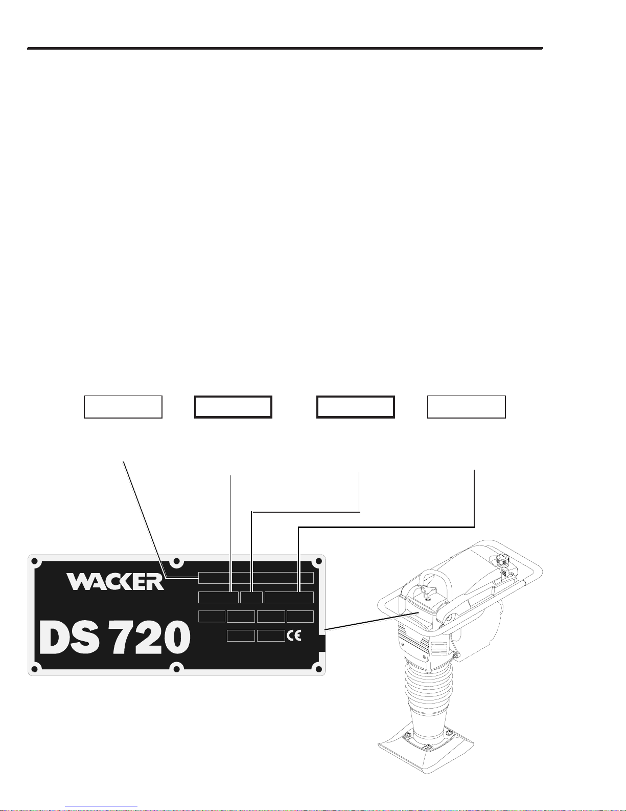
Nameplate / Typenschild / Placa de Identificación / Plaque signalétique
A nameplate listing the Model Number, Item Number, Revision, and Serial Number is attached to each unit. Please
record the information found on this plate so it will be available should the nameplate become lost or damaged. When
ordering parts or requesting service information, you will always be asked to specify the model, item number,
revision number, and serial number of the unit.
Ein Typenschild mit Typ, Artikelnummer, Version und Maschinen-Nummer ist an jedem Gerät angebracht. Die Daten
von diesem Schild bitte notieren, damit sie auch bei Verlust oder Beschädigung des Schildes noch vorhanden sind.
Der Typ, die Artikel-Nummer, die Versions-Nummer und die Maschinen-Nummer sind bei der Ersatzteilbestellung
oder Nachfragen bezüglich Service-Informationen stets erforderlich.
Una placa de identificación con el modelo, número de referencia, nivel de revisión y número de serie ha sido añadida
en cada máquina. Favor de anotar los datos en la placa en caso de que la placa de identificación sea destruida o
perdida. En todos los pedidos para repuestos necesita siempre el modelo, el número de referencia, el nivel de
revisión y el número de serie de la máquina en cuestión.
Une plaque signalétique mentionnant le modèle, le numéro de référence, le niveau de revision et le numéro de série
est fixée sur chaque machine. Veuillez noter les informations relevées sur cette plaque de façon à ce qu’elles soient
toujours disponibles si la plaque signalétique venait à être perdue ou endommagée. Lorsque vous commandez des
pièces détachées ou vous sollicitez des informations auprès-vente, on vous demandera toujours de préciser
le modèle, le numéro de référence, le niveau de revision et le numéro de série de la machine.
My machine’s numbers are / Die Nummern meines Gerätes sind /
Los números de mi máquina son / Les numéros de ma machine sont :
Model number
Typ
Modelo
Modèle
Wacker Corporation
Menomonee Falls, WI 53051 USA
Item Number
Artikel-Nummer
Número de referencia
Numéro de référence
Model
DS720DS720
DS720
DS720DS720
Item Number
00090590009059
0009059
00090590009059
MADE
IN USA
lbskg
dB(A)
Rev.
101101
101
101101
Serial Number
50101015010101
5010101
50101015010101
kW
Manuf. Yr.
Revision
Version
Nivel de revisión
Niveau de revision
hp
114084
Serial Number
Maschinen-Nummer
Número de Serie
Numéro de Série
1027SD90
ii
Page 5

This machine may be covered by one or more of the following patents:
111891
OF THESE U.S. PATENTS:
4643611; 4555238; 5564375; 5586630; 4419048
WACKER MACHINES PROTECTED BY ONE OR MORE
Dieses Gerät ist unter einem oder mehreren der folgenden Patente geschützt:
Puede ser que las patentes a continuación sean válidas para esta máquina:
Cette machine peut être protégée sous les brevets d’invention ci-dessous :
DS720
PATENT PENDING
111545
iii
Page 6

DS720
Keep this manual or a copy of it with the machine. If you lose this manual or need an
additional copy, please contact WACKER Corporation. This machine is built with user
safety in mind, however, it can present hazards if improperly operated and serviced.
Follow operating instructions carefully! If you have questions about operating or
servicing this equipment, please contact WACKER Corporation.
Diese Betriebsvorschrift oder eine Kopie stets mit der Maschine aufbewahren. Weitere
Kopien sind von WACKER Corporation erhältlich. Diese Maschine ist unter Betracht der
Verbrauchersicherheit entwickelt, kann jedoch bei unfachgemäßem Gebrauch oder Wartung
Gefahren darstellen. Die Vorschriften genauestens befolgen! Sollten Sie Fragen bezüglich
Betrieb oder Service dieser Maschine haben, so steht WACKER Corporation Ihnen gerne zur
Verfügung.
Mantenga este manual o una copia de el con la máquina. Si se pierde o si Ud. desea un
ejemplar adicional, favor comunicarse con WACKER. Esta máquina fue fabricada con la
seguridad del usuario en mente; sin embargo, situaciones peligrosas pueden presentarse
si la máquina es utilizada o mantención es dada inapropiadamente. Siga las instrucciones
de operación cuidadosamente. Si Ud. tiene preguntas acerca de la operación o mantención
de este equipo, favor de comunicarse con WACKER CORPORATION.
Conserver ce manuel ou une copie de celui-ci avec la machine. Si vous perdez ce manuel
ou que vous avez besoin d’un exemplaire supplémentaire, veuillez contacter WACKER
Corporation. Cette machine est construite dans le soucis de la sécurité de l’utilisateur, elle
peut cependant présenter des dangers si elle est utilisée et entretenue de façon incorrecte.
Respectez attentivement les consignes d’utilisation ! Si vous avez des questions concernant
l’utilisation ou l’entretien de cet équipement, veuillez contacter WACKER Corporation.
iv
Page 7

DS720
Operating Information
Table of Contents
1.1 Safety Information ................................................................................... 1A-2
1.2 Operating Safety...................................................................................... 1A-3
1.3 Operator Safety while using Internal Combustion Engines ...................... 1A-4
1.4 Service Safety ......................................................................................... 1A-4
1.5 Sound Measurements.............................................................................. 1A-5
1.6 Vibration Measurements .......................................................................... 1A-5
1.7 Technical Data ......................................................................................... 1A-5
1.8 Safety & Informational Labels .................................................................. 1A-6
1.9 Operating Labels ..................................................................................... 1A-7
1.10 Dimensions .............................................................................................. 1A-8
1.11 Description............................................................................................... 1A-8
1.12 Recommendations on compaction........................................................... 1A-9
1.13 Transportation ......................................................................................... 1A-9
1.14 Recommended Fuel .............................................................................. 1A-10
1.15 Before Starting....................................................................................... 1A-10
1.16 To Start.................................................................................................. 1A-10
1.17 Operation ............................................................................................... 1A-10
1.18 To Stop .................................................................................................. 1A-10
1.19 Proper Compaction................................................................................ 1A-11
1.20 Periodic Maintenance Schedule ............................................................ 1A-11
1.21 Servicing Air Cleaner ............................................................................. 1A-12
1.22 Lubrication ............................................................................................. 1A-13
1.23 Shoe Hardware ...................................................................................... 1A-14
1.24 Long-Term Storage................................................................................ 1A-14
1.25 Troubleshooting ..................................................................................... 1A-14
1A
1A-1
Page 8

1A OPERATION DS720
1.1 Safety Information
This manual contains DANGER, WARNING, CAUTION, and NOTE callouts which must be followed to reduce the
possibility of personal injury, damage to the equipment, or improper service.
This is the safety alert symbol. It is used to alert you to
potential personal injury hazards. Obey all safety messages
!
that follow this symbol to avoid possible injury or death.
!
DANGER
DANGER indicates an imminently hazardous
situation which, if not avoided, will result in
death or serious injury.
!
WARNING
WARNING indicates a potentially hazardous
situation which, if not avoided, could result in
death or serious injury.
!
CAUTION
CAUTION indicates a potentially hazardous
situation which, if not avoided, may result in
minor or moderate injury.
CAUTION: Used without the safety alert symbol,
CAUTION indicates a potentially hazardous situation
which, if not avoided, may result in property damage.
Note:
information important to a procedure.
Contains additional
1A-2
Page 9

DS720 OPERATION 1A
1.2 Operating Safety
Familiarity and proper training are required for the safe operation of equipment! Equipment operated improperly or
by untrained personnel can be dangerous! Read the operating instructions and familiarize yourself with the
location and proper use of all instruments and controls. Inexperienced operators should receive instruction from
someone familiar with the equipment before being allowed to operate the rammer.
!
WARNING
NEVER operate rammer in applications for which it
is not intended.
NEVER allow improperly trained personnel to operate rammer.
NEVER touch hot muffler, engine cylinders, or
cooling fins. Burns will result.
NEVER use accessories or attachments which are
not recommended by WACKER for rammer. Damage to rammer and/or injury to user may result.
NEVER leave a running machine unattended.
NEVER run machine indoors or in an enclosed
area such as a deep trench unless adequate ventilation is provided. Exhaust gas from the engine
contains poisonous carbon monoxide gas; exposure to carbon monoxide can cause loss of consciousness and may lead to death. WACKER
offers electric rammers for applications in enclosed areas.
NEVER tamper with or disable the function of operating controls.
ALWAYS be sure operator is familiar with proper
safety precautions and operation techniques before using rammer.
ALWAYS wear protective clothing when operating
rammer. Wear goggles or safety glasses, hearing
protection, and safety shoes.
ALWAYS keep hands, feet, and loose clothing away
from moving parts of rammer.
ALWAYS use common sense and caution when
operating rammer.
ALWAYS be sure rammer will not tip over, roll, slide,
or fall when not being operated.
ALWAYS turn engine OFF when rammer is not being
operated.
ALWAYS guide the rammer in such a way that the
operator is not squeezed between the rammer and
solid objects. Special care is required when working
on uneven ground or when compacting coarse material. Make sure to stand firmly when operating the
machine under such conditions.
ALWAYS read, understand, and follow procedures
in Operator’s Manual before attempting to operate
equipment.
ALWAYS be sure that all other persons are at a
safe distance from the rammer. Stop the machine
if people step into the working area of the machine.
ALWAYS operate the rammer in such a way that
there is no danger of it turning over or falling in, when
working near the edges of breaks, pits, slopes, trenches
and platforms.
1A-3
Page 10

1A OPERATION DS720
1.3 Operator Safety while using Internal Combustion Engines
Internal combustion engines present special hazards during operation and fueling! Failure to follow the safety
guidelines described below could result in severe injury or death.
!
DANGER
DO NOT smoke while operating rammer.
DO NOT smoke when refueling engine.
DO NOT refuel hot or running engine.
DO NOT refuel engine near open flame.
DO NOT spill fuel when refueling engine.
DO NOT operate rammer near open flames.
ALWAYS refill fuel tank in well-ventilated area.
ALWAYS replace fuel tank cap after refueling.
ALWAYS check fuel lines, fuel cap, and fuel tank for
leaks and cracks before starting engine. Do not run
machine if fuel leaks are present, or fuel cap or fuel
lines are loose.
1.4 Service Safety
Poorly maintained equipment can become a safety hazard! In order for the equipment to operate safely and properly
over a long period of time, periodic maintenance and occasional repairs are necessary.
!
WARNING
DO NOT attempt to clean or service rammer while it
is running.
DO NOT operate rammer with safety devices or
guards removed or not in working order.
ALWAYS replace safety devices and guards after
repairs and maintenance.
ALWAYS keep area around muffler free of debris in
order to reduce the chance of an accidental fire.
DO NOT operate rammer without air cleaner.
DO NOT remove air cleaner paper element,
precleaner, or air cleaner cover while operating
rammer.
DO NOT alter engine speeds. Run engine only at
speeds specified in Technical Data Section.
1A-4
ALWAYS do Periodic Maintenance as recommended
in Operator’s Manual.
ALWAYS clean debris from engine cooling fins.
ALWAYS replace worn or damaged components
with original spare parts designed and recommended
by WACKER for servicing this rammer.
Page 11

DS720 OPERATION 1A
1.5 Sound Measurements
The operating sound levels, measured per the requirements of Appendix 1, Paragraph 1.7.4.f of the EC-Machine
Regulations, are:
- the sound pressure level at operator's location (LpA) = 92 dB(A).
- the sound power level (L
These sound values were determined according to ISO 3744 for the sound power level (LWA) and ISO 6081 for the
sound pressure level (LpA) at the operator's location.
1.6 Vibration Measurements
The operating hand/arm vibration level, measured per the requirements of enclosure 1, Paragraph 2.2 or 3.6.3 of the
EC-Machine Regulations, is approximately 16 m/s2.
The weighted effective acceleration value was determined according to ISO 8662 Part 1.
The sound and vibration measurements were obtained with the machine operating on crushed gravel at nominal
engine speed.
1.7 Technical Data
) = 103 dB(A).
WA
ledom/ekamenignE 2KWD-EA04LramnaY
epytenignE enigneleseidekorts-4,rednilyc-elgnis,deloocria
rewopenignE)Wk(pH)1.3(2.4
lluf-deepsenignEmpr0063
eldi-deepsenignEmpr002±0021
tnemegagnehctulc-deepsenignEmpr002±0002
dloc-ecnaraelcevlaV)mm(.ni)51.0(600.0
noitacirbulenignEedargliorettebroCC
yticapaclioenignE)lm(.zo)008(72
tnemecalpsidnotsiPmc
3
epytleuF 54>enatec,leseiD2.oN
yticapacknatleuF)l(.lag)7.5(5.1
noitpmusnocleuF)h/l(.rh/.lag)9.0(52.0
thgiewgnitarepO)gk(.sbl)57(561
)2(
etarnoissucreP
.nim/sekorts007–056
)1(
991
krowekortselgniSpkm/J001
noitacirbulmetsysgnimmaRedarglio03EAS
yticapacliometsysgnimmaR)lm(.zo)098(03
(1)
Refer to Section 1.22
(2)
Percussion rate can be adjusted with the throttle lever.
Lubrication.
)pu(eohsgnimmarehtfoekortS)mm(.ni)57(3ot
1A-5
Page 12
1A OPERATION DS720
2
3
4
5
1
2
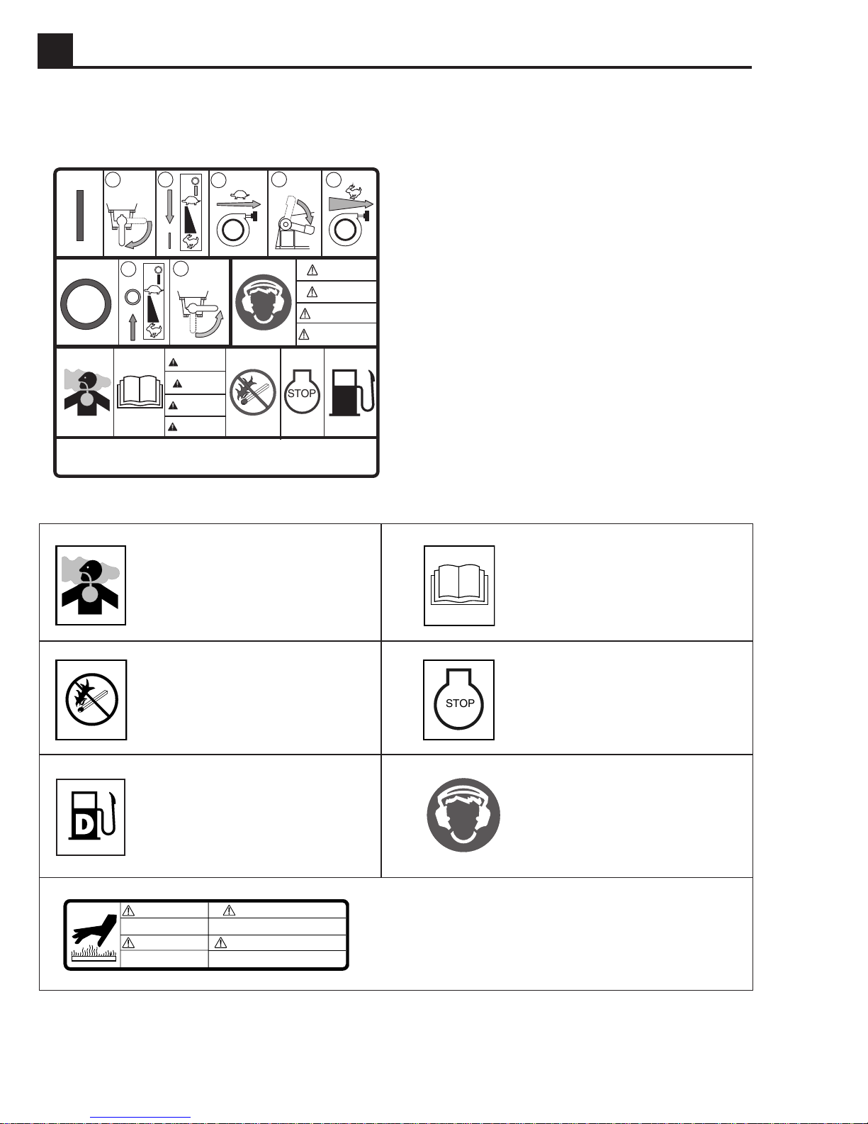
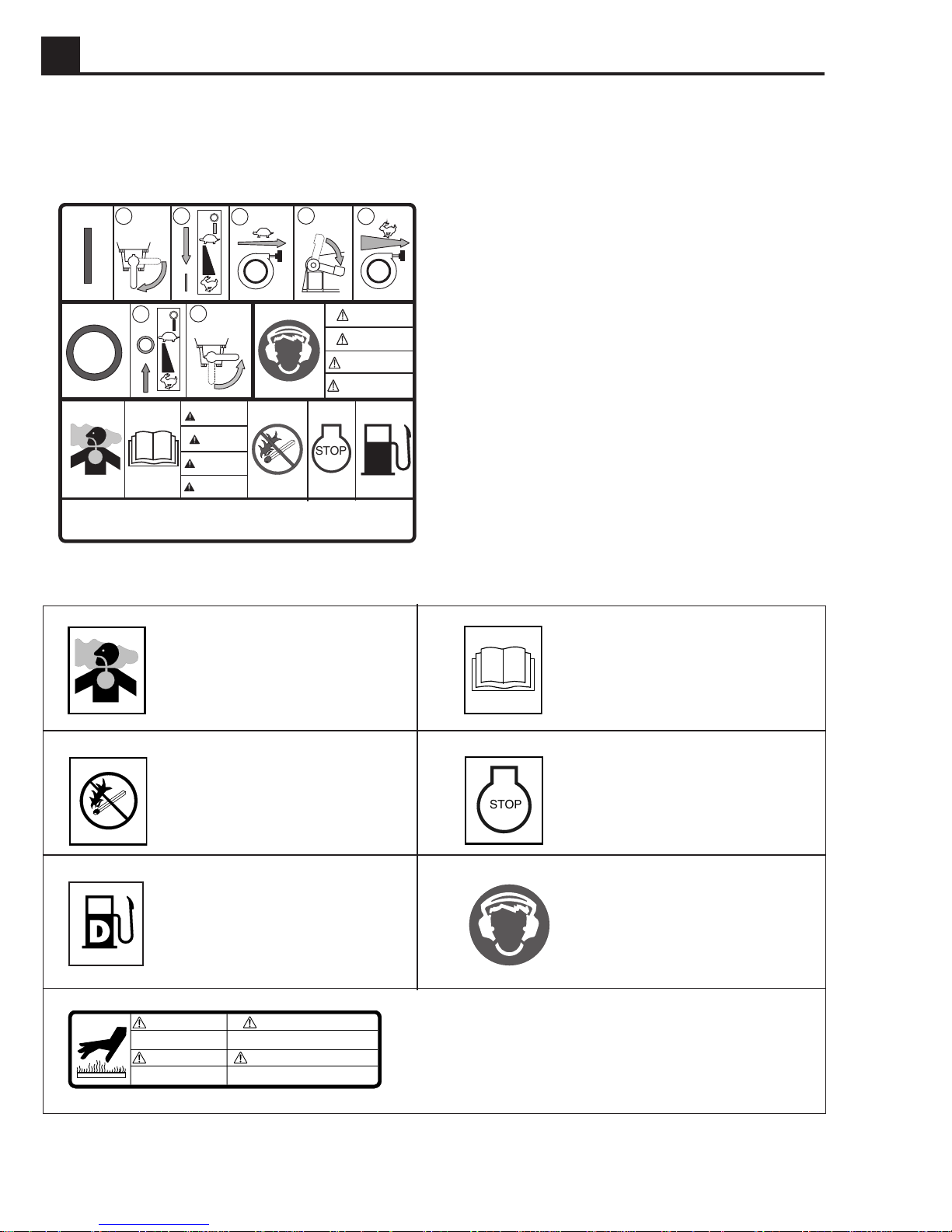
1.8 Safety & Informational Labels
This WACKER machine uses international pictorial labels where needed. These labels are described below:
1
This molded-in label contains important safety and
operating information. If it becomes illegible, the
cover must be replaced. Refer to the Parts Book for
ordering information.
WARNING
WARNUNG
ADVERTENCIA
AVERTISSEMENT
DANGER
GEFAR
PELIGRO
DANGER
STOP
D
DIESEL
112419-6
Label Meaning Label Meaning
Danger of asphyxiation!
No sparks, flames, or burning objects near fuel tank.
Diesel fuel.
STOP
Read operator’s manual for
machine information.
Stop engine before fueling.
Wear hearing protection
when operating machine.
WARNING
REPLACE GUARD
WARNUNG
SCHUTZ WIEDER
MONTIEREN
ADVERTENCIA
MONTE DE NUEVO PROTECTOR
AVERTISSEMENT
REMETTRE PROTECTEUR
1A-6
Hot surface!
Replace guard!
115414
Page 13
DS720 OPERATION 1A
2
5
1
2
2
3
4
5
1
2
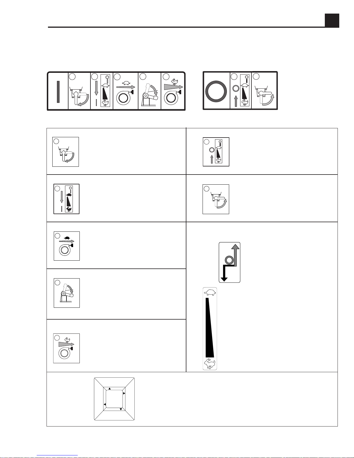
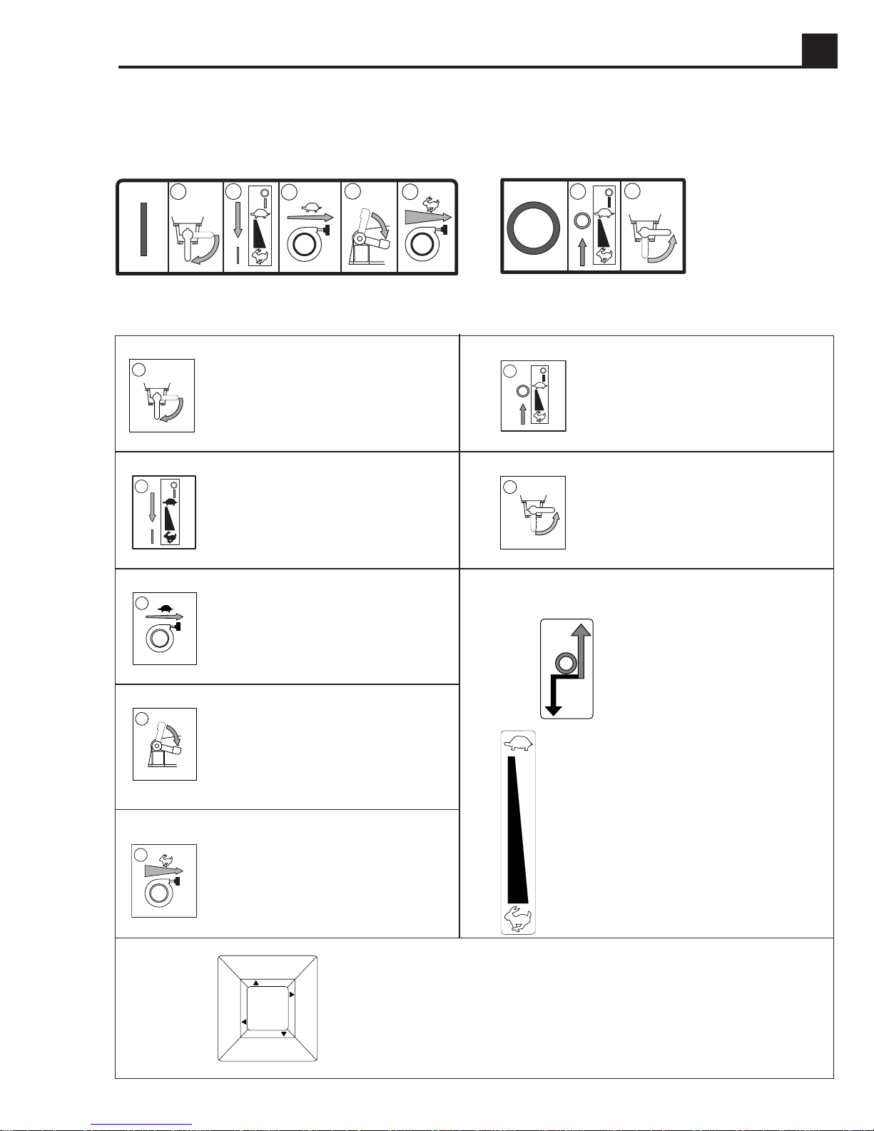
1.9 Operating Labels
This WACKER machine uses international pictorial labels where needed. These labels are described below:
1
112419-6b
112419-6c
Label Meaning
1
Turn fuel valve to
the “open” position.
Place throttle control lever
in the “start” position.
3
Slowly pull rewind starter.
4
Press decompression
lever down.
Label Meaning
Place throttle control lever in
the “stop” position
Turn fuel valve to
the “closed” position.
Throttle control lever:
Stop
Start / Idle
Quickly pull rewind starter.
SERIOUS INJURY IF STRUCK
BY COMPRESSED SPRING
OR COVER! READ
REPAIR MANUAL!
WARNING
!
ATTENTION
!
REPARATION!
LIRE NOTICE DE
ET COUVERCLE SONT COMPRIMES!
DANGER DE BLESSURE - RESSORTS
ADVERTENCIA
FEDERN UND DECKEL STEHEN
UNTER DRUCK! REPARATUR-
ANLEITUNG DURCHLESEN!
VERLETZUNGSGEFAHR -
!
WARNUNG
!
DE REPARACION!
DE LA TAPA! LEA MANUAL
ESTA BAJO PRESION O DEBAJO
SERIO PELIGRO SI EL RESORTE
79687
Run
115416
89366
WARNING! Serious injury if struck by compressed
spring or cover. If the spring system cover is removed
improperly, the springs can eject.
1A-7
Page 14
1A OPERATION DS720
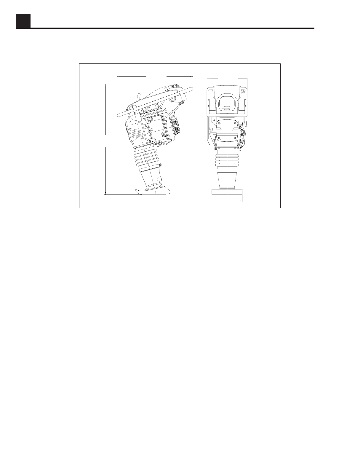
1.10 Dimensions
in. (mm)
1.11 Description
39.4
(1000)
27.6 (700)
14.6 (372)
13 (330)
1027SD76
Applications
• Civil engineering jobs for the compaction of all types of soils, especially cohesive soils.
• Trenches for cables, water lines, gas pipelines, backfills and structural fills, etc.
• Stabilization of slopes, dams, dikes and levees.
• Road construction for the compaction of base course concrete, marginal strip and sub-surface compaction jobs.
• Road repairs of all types.
• Building construction for the compaction of concrete and sub-soils in cellars and shed floors.
• Garden construction and parks for the stabilization of roads and paths.
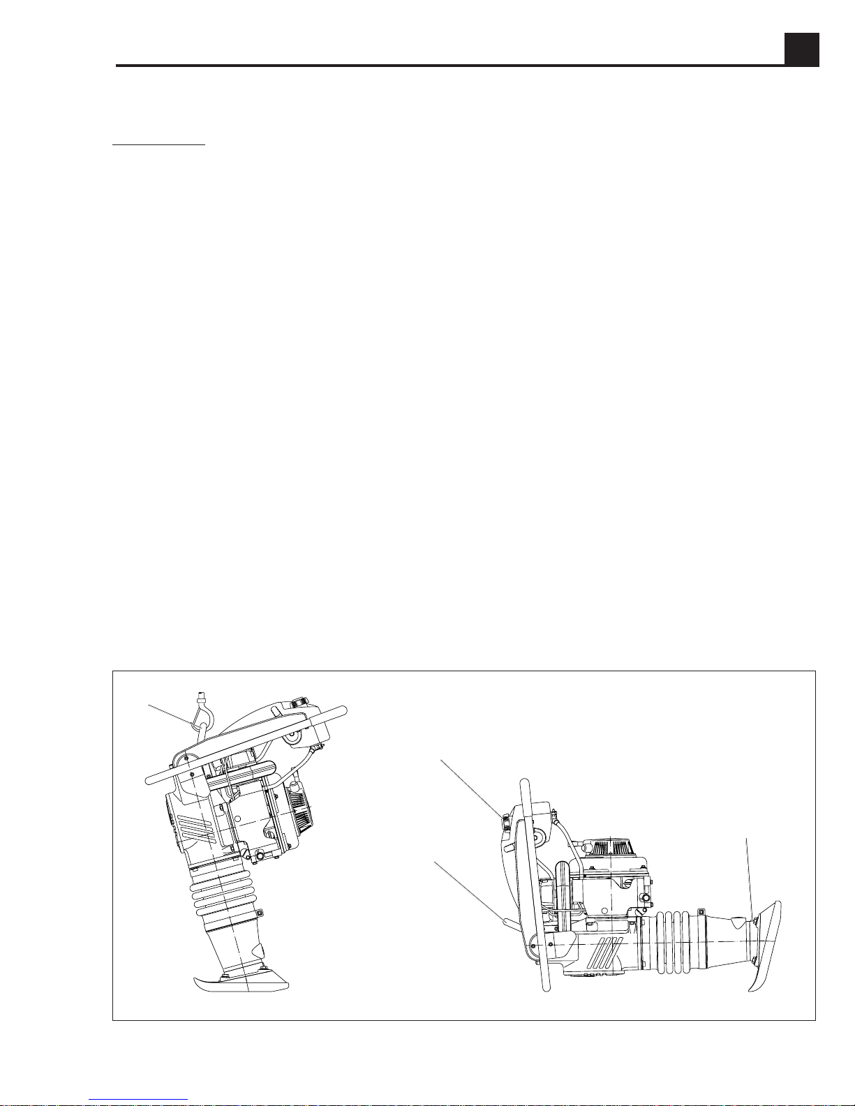
Description of function
The vibration required for compaction is produced by the ramming system, which is firmly attached to the ramming shoe.
The engine, which is flanged to the crankcase and is held in place by four screws, drives the ramming system over a
gear transmission and a connecting rod. The engine torque is transmitted by means of a centrifugal clutch.
The centrifugal clutch interrupts the flow of power to the ramming system at low engine speeds, thus allowing for a
perfect idling of the engine. The advance movement in forward direction of the rammer is ensured by means of the tilt
of the ramming system.
The engine can be switched off with the throttle control.
The drive engine works according to the diesel principle, and is started mechanically by means of a recoil starter. The
engine is air cooled and the air necessary for combustion is directed through a precleaner and a dry-type air filter.
The guide handle and frame are mounted on the ramming system with a set of shockmounts, therefore assuring a
minimum transmission of vibrations to the hands of the operator.
1A-8
Page 15
DS720 OPERATION 1A
1.12 Recommendations on compaction
Soil conditions:
The maximum compaction depth of the soil depends on several factors relating to the nature of the soil, such as water
content, grain-size distribution, etc. It is therefore not possible to specify a given layer depth.
Recommendation: In each case determine the maximum possible compaction depth through compaction tests and
soil samples.
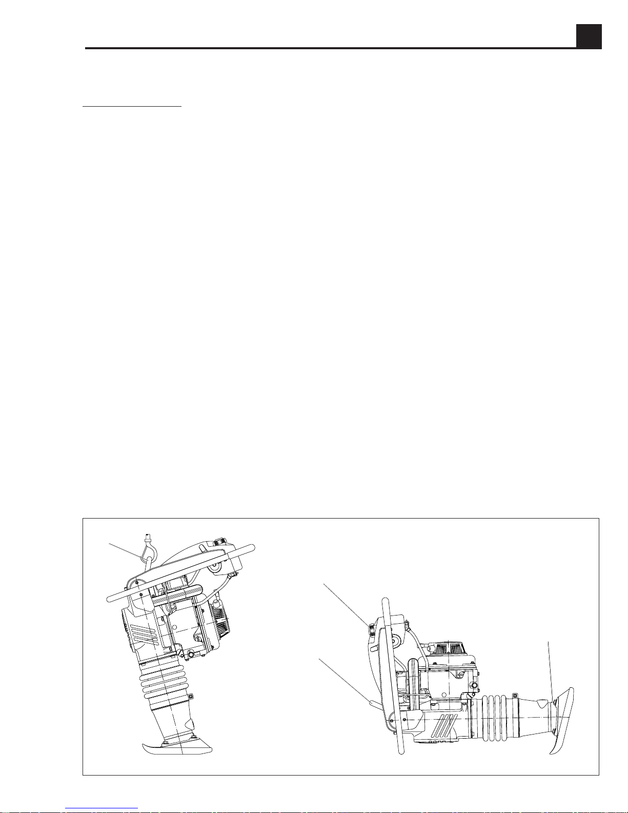
1.13 Transportation
1. Always shut off the engine and close the fuel valve when transporting the rammer.
2. Use lifting equipment with minimum lifting capacity of 220.5 lbs. (100 kg).
3. Use the central lifting point (a) when lifting the rammer.
4. WACKER recommends transporting rammers upright whenever possible; however, a rammer should not be
allowed to fall over.
If the rammer cannot be secured in the upright position, tie down the rammer to the transport vehicle to prevent
it from tipping, falling, or rolling. Lay the rammer down only as shown below and tie it to the vehicle at points (b)
and (c).
CAUTION: Drain the fuel tank as required to prevent fuel leaking from the cap (d).
CAUTION: After transporting the rammer horizontally, upright the rammer and allow the oil to drain back through the
engine. It may take up to 45 minutes for the oil level to recover. Failure to do so may result in engine damage.
Note:
Refer to the specifications in the safety instructions.
a
d
c
b
1027SD77
1A-9
Page 16
1A OPERATION DS720
1.14 Recommended Fuel
Use only pure diesel fuel. Close the fuel cap immediately.
It is important to maintain cleanliness to avoid problems
with the fuel injection system, and to prevent premature
clogging of the fuel filter. To avoid contamination, DO
NOT open the fuel line or the fuel pump or any other point
of the fuel system, not even to bleed air. The fuel pump
will bleed automatically. This applies even if the fuel tank
was run dry. If this happens, refill the fuel tank.
1.15 Before Starting
1. Read safety instructions at the beginning of this
manual.
2. Perform daily maintenance items.
3. Place rammer on loose soil or gravel. DO NOT start
rammer on hard surfaces such as asphalt or concrete.
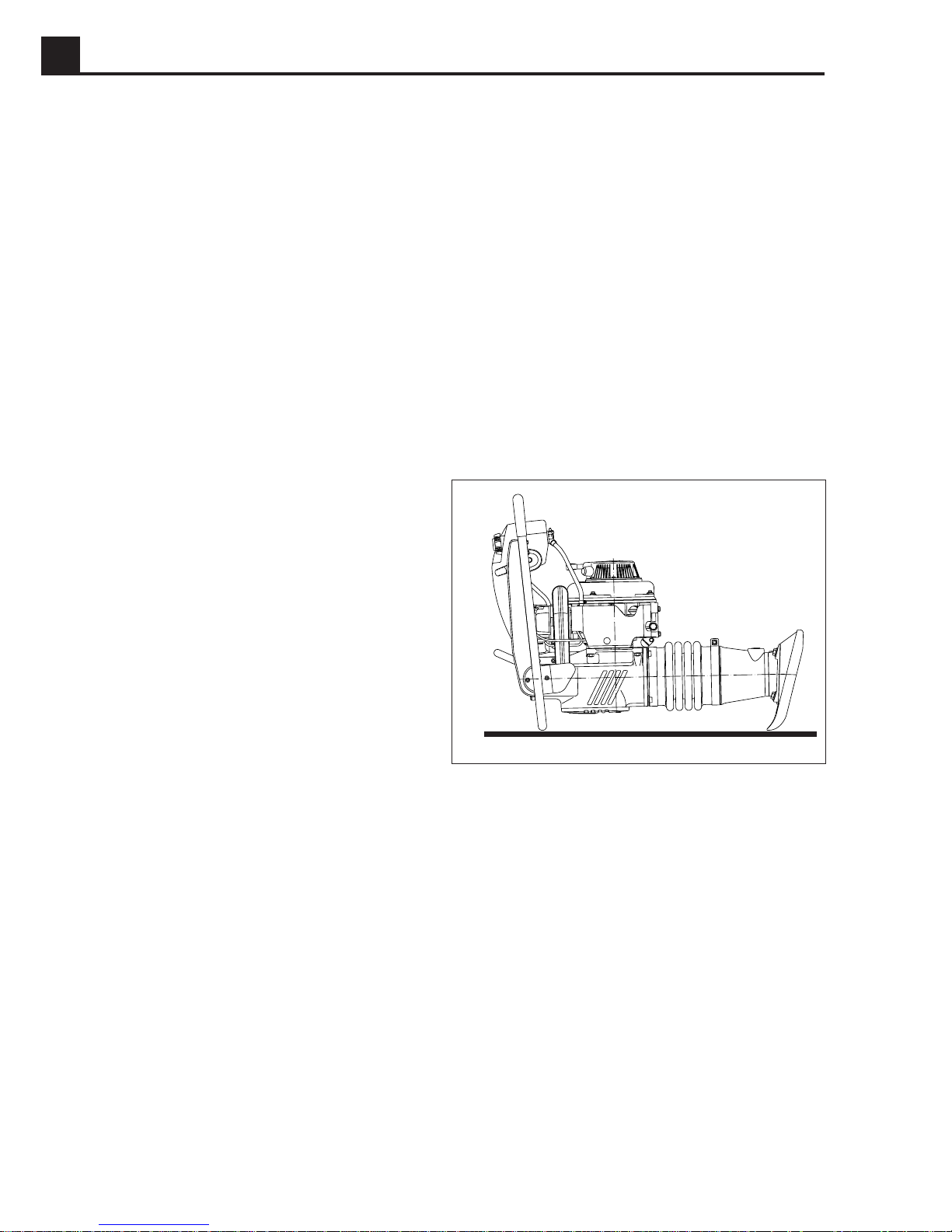
1.17 Operation
Keep vibratory rammer clean and dry. Avoid no-load
strokes. Never allow the rammer to run full throttle when
forcing away material or when lifting the equipment.
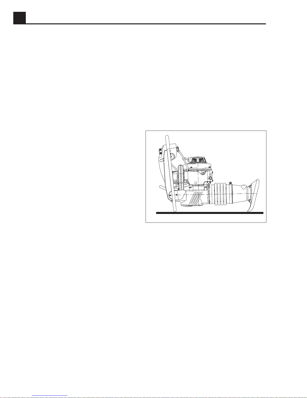
CAUTION: To prevent damage to the rammer, do not
allow the rammer to run on its side.
If the rammer should tip on its side, place the rammer in
the position shown below, then shut off the engine by
moving the throttle control lever through the detent to the
off position.
Note:
The rammer may continue to run for 5–10 seconds
after the throttle is placed to off, then the engine will stop.
1.16 To Start
1. Turn the fuel valve to the “0” (open) position.
2. Open the throttle control lever to the “start” position.
3. Slowly pull the recoil starter rope handle until resistance is met, then release.
4. Press down on the decompression lever. (When
pulling the recoil starter rope, the decompression
lever will automatically return to initial position).
5. Quickly pull the recoil starter rope.
1027SD77
1.18 To Stop
Switch off the engine as follows:
CAUTION: Do not switch off engine by means of the
decompression lever.
1. Reduce engine rpm’s and let it run for a short while.
CAUTION: Do not switch off engine directly from full
power.
2. Shut off the engine by moving the throttle control lever
through the detent to the off position. The engine will
stop.
3. Close the fuel valve.
Note:
For short-term operation interruption, it is only
necessary to stop the engine.
1A-10
Page 17

DS720 OPERATION 1A
1.19 Proper Compaction
• Run the rammer at the full throttle position for maximum performance.
• Guide the rammer with its handle. Allow machine to
pull itself forward. DO NOT try to over-power the
machine.
• For best compaction, the shoe must hit the ground flat
(a), not on its toe or heel. This will save on excessive
shoe wear.
1.20 Periodic Maintenance Schedule
a
1027SD81
yliaD
eludehcSecnanetniaM
erofeb
gnitrats
retfA
5tsrif
sruoh
yrevE
keew
52ro
sruoh
yrevE
htnom
001ro
sruoh
3yrevE
shtnom
003ro
sruoh
5yrevE
shtnom
005ro
sruoh
levelleufkcehC •
levellioenignekcehC •
ssalgthgisnilioremmarkcehC •
skaelrofsgnittifdna,pac,enilleufkcehC
skcarcro
•
tifdnaegamadrofswollebkcehC •
erawdraheohsgnimmarnethgiT ••
swercsrednilycenignenethgitdnakcehC ••
erawdrahlanretxenethgitdnakcehC ••
snifgniloocenignenaelC •
)1(
lioenigneegnahC
)1(
retliflioenignenaelC
•
•
retratsliocernaelC •
liometsysgnimmaregnahC
retliflioenigneecalpeR •
(1)
Perform initially after first 50 hours of operation.
Note:
If engine performance is poor, check, clean, and replace air filter elements as needed.
)1(
ecnaraelcevlavtsujdadnakcehC1(•
ts
) •
•
ecalperronaelc,retlifleufkcehC •
1A-11
Page 18
1A OPERATION DS720
1.21 Servicing Air Cleaner
Under normal operating conditions the air cleaner elements will not require cleaning and should not be removed from
the machine. If the elements do become plugged with dirt, the engine will begin to lose power. In this case, the elements
can be removed and cleaned as described below. Replace an element if it becomes so plugged with dirt it can no longer
be cleaned.
CAUTION: NEVER run engine without air cleaner. Severe engine damage will occur.
!
WARNING
NEVER use gasoline or other types of low flash
point solvents for cleaning the air cleaner. A fire or
explosion could result.
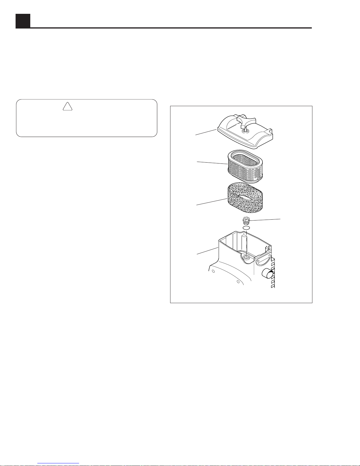
The engine is equipped with a dual element air cleaner.
a
1. Remove air cleaner cover (a). Remove precleaner
and paper element and inspect them for holes or
tears. Replace if damaged.
2. Precleaner (b):
Clean with low-pressure compressed air. When very
soiled, wash in solution of mild detergent and warm
water. Rinse thoroughly in clean water. Allow to dry
thoroughly before re-installing.
Note:
3. Paper element (c)
Tap element lightly to remove excess dirt. Replace
paper element if it appears heavily soiled.
4. Wipe out filter housing (d) with a clean rag.
Do not oil precleaner.
CAUTION: Do not allow dirt into the engine intake port
while cleaning—damage to the engine will result.
c
b
e
d
1016SD95
1A-12
Page 19
DS720 OPERATION 1A
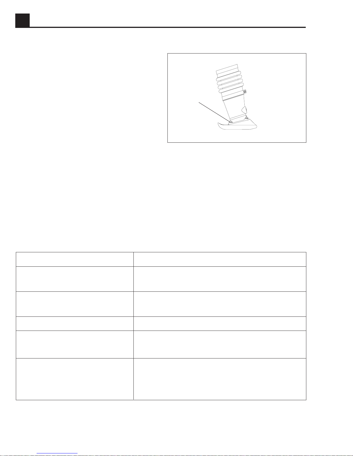
1.22 Lubrication
Engine oil
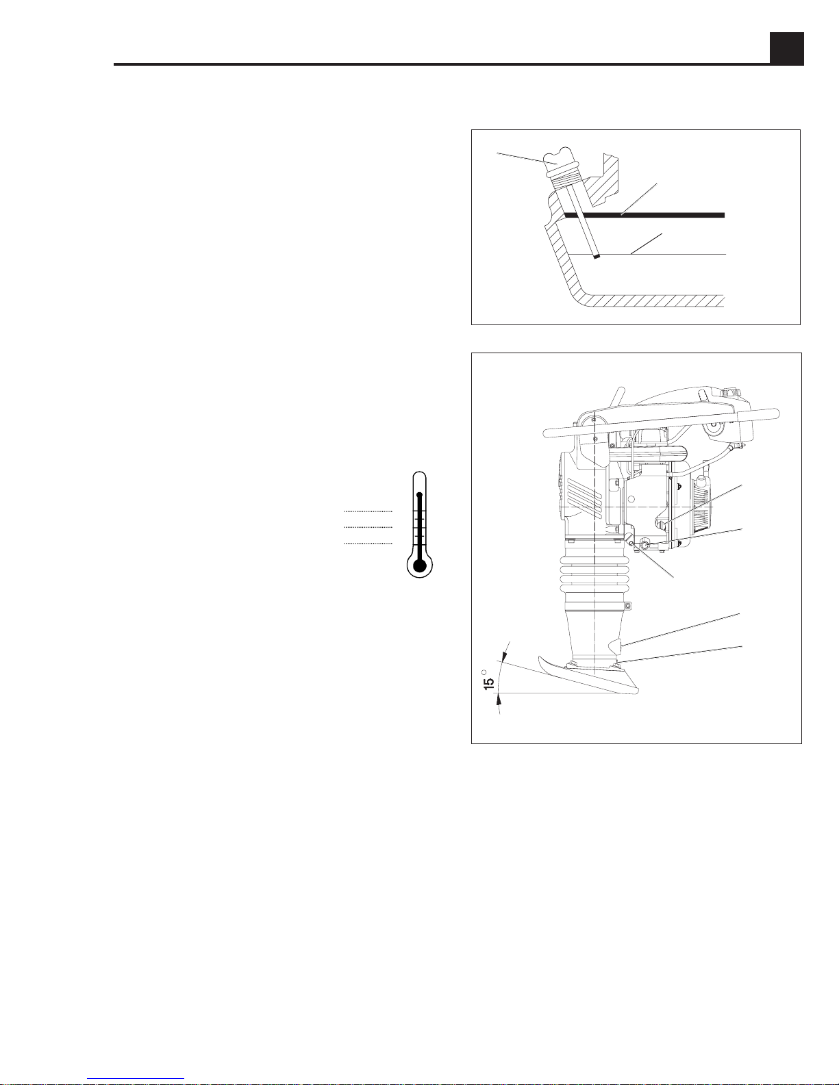
Check oil level:
Tilt the machine backwards approx. 15° until the engine
is level by placing a wedge under the shoe. The oil
surface should reach NO HIGHER THAN the bottom of
the filler neck “H”, but no lower than “L” (see drawing) or
visible on the dipstick (f) when it is inserted (not screwed)
into the filler neck.
Add CC or better quality oil through the filler neck as
required.
CAUTION: DO NOT overfill. The oil level should just
reach the bottom of the filler neck. Too much oil can
cause damage to the engine and the rammer.
Note:
After transporting the rammer horizontally, upright
the rammer and allow the oil to drain back through the
engine. It may take up to 45 minutes for the oil level to
recover.
f
H
L
1036SD38
Oil change:
1. Let the engine warm up, then shut
it off.
2. Place the rammer so that the en-
gine is level.
3. Unscrew the engine oil drain plug
SAE 40
SAE 20
SAE 10
SAE 5
°C °F
20
0
-20 -4
(g) and let oil flow out.
4. Screw in the oil drain plug.
5. Fill with approx. 27 oz. (800 ml) of oil through the oil
fill opening. Refer to
Oil filter:
1. Drain the oil as above.
2. Unscrew the bolt (h) on the oil filter cover and pull out
the oil filter.
To clean the oil filter:
Use low pressure compressed air to remove any
visible debris on the oil filter.
To replace the oil filter:
Discard the old oil filter in accordance with environmental regulations. Replace with WACKER-supplied
oil filter and O-ring.
Check oil level
, above.
f
68
32
g
h
j
k
1027SD78
Ramming system
Check oil level:
1. Place the rammer so it is resting on its shoe.
2. Check the oil level through oil sightglass (j).
3. If the oil is not visible, refill through the oil fill opening
(e) with HD brand quality SAE 40 oil.
4. Close the oil fill opening.
Oil change:
1. Unscrew the oil drain plug (k) located below the oil
sightglass.
2. Tip the rammer over and allow oil to drain.
3. Screw in the oil drain plug.
4. Remove the oil fill plug (e) located at the top of the
crankcase. Fill with 30 oz. (890 ml) HD brand quality
SAE 40 oil through the oil fill opening.
5. Screw in the oil fill plug.
1A-13
Page 20
1A OPERATION DS720
1.23 Shoe Hardware
On new machines, or after replacing shoe, check and
tighten shoe hardware
operation. Inspect hardware every week thereafter.
Torque hardware as specified.
1.24 Long-Term Storage
1. Drain fuel from the fuel tank.
2. Start the engine and run it until remaining fuel is used.
(a) after the first 5 hours of
63 ft.lbs.
(85.5 Nm)
a
1027SD82
3. Cover the rammer and store in a clean, dry location.
1.25 Troubleshooting
Problem / Symptom
Engine does not start, or stalls.
Engine does not accelerate,
is hard to start, or runs erratically.
Engine overheats.
Engine runs; rammer does not tamp.
1. No fuel in tank.
2. Fuel valve closed.
1. Crankshaft seals are leaking.
2. Air cleaner may be clogged.
1. Clean cooling fins and fan blades.
1. Inspect clutch for damage. Replace if necessary.
2. Broken connecting rod or crankgear.
3. Low engine performance. Compression loss.
Reason / Remedy
Engine runs, rammer operation is erratic.
1A-14
1. Oil/grease on clutch.
2. Broken/worn springs.
3. Soil buildup on ramming shoe.
4. Broken parts in ramming system or crankcase.
5. Engine operating speed is too high.
Page 21

DS720
Betriebsanweisungen
Inhaltsverzeichnis
1.1 Sicherheitsvorschriften ............................................................... 1B-2
1.2 Betriebssicherheit ....................................................................... 1B-3
1.3 Sicherheit für Bedienungspersonal beim Gebrauch
von Verbrennungsmotoren ........................................................ 1B-4
1.4 Service-Sicherheit ...................................................................... 1B-4
1.5 Geräuschmessungen ................................................................. 1B-5
1.6 Vibrationsmessungen ................................................................ 1B-5
1.7 Technische Daten ...................................................................... 1B-5
1.8 Sicherheits- und Hinweisaufkleber ............................................ 1B-6
1.9 Betriebs-Aufkleber ...................................................................... 1B-7
1.10 Abmessungen ............................................................................ 1B-8
1.11 Beschreibung ............................................................................. 1B-8
1.12 Empfehlung zum Verdichten...................................................... 1B-9
1.13 Transport .................................................................................... 1B-9
1.14 Empfohlener Kraftstoff ............................................................. 1B-10
1.15 Vor dem Anlassen .................................................................... 1B-10
1.16 Anlassen .................................................................................. 1B-10
1.17 Betrieb ...................................................................................... 1B-10
1.18 Abstellen .................................................................................. 1B-10
1.19 Richtige Verdichtung ................................................................ 1B-11
1.20 Periodischer Wartungsplan ...................................................... 1B-11
1.21 Luftfilter Instandhaltung ........................................................... 1B-12
1.22 Schmierung .............................................................................. 1B-13
1.23 Stampfeinsatz-Kleinmaterial .................................................... 1B-14
1.24 Langfristige Lagerung .............................................................. 1B-14
1.25 Fehlersuche ............................................................................. 1B-14
1B
ger
1B-1
Page 22

1B BETRIEB DS720
!
1.1 Sicherheitsvorschriften
Diese Betriebsanleitung enthält Sicherheitsvorschriften der Kategorien: GEFAHR, WARNUNG, VORSICHT und
ANMERKUNG. Diese sind zu befolgen, damit die Gefahr von Verletzung, Beschädigung der Ausrüstung oder
nichtfachgerechtem Service verringert wird.
Dies ist ein Sicherheits-Warnsymbol, daß vor möglicher
Verletzungsgefahr warnt. Alle unter diesem Warnsymbol
!
gezeigten Sicherheitsvorschriften müssen befolgt werden,
um die Gefahr von Verletzungen oder Tod zu vermeiden.
GEFAHR
GEFAHR weist auf eine unmittelbare Gefahrsituation
hin, die bei Nichtbeachtung dieser Warnung zu
schwerer Verletzung oder Tod führen kann.
WARNUNG
!
WARNUNG weist auf eine mögliche Gefahrsituation
hin, die bei Nichtbeachtung dieser Warnung zu
schwerer Verletzung oder Tod führen kann.
VORSICHT
!
VORSICHT weist auf eine mögliche Gefahrsituation
hin, die bei Nichtbeachtung dieser Warnung zu
leichter bis mittlerer Verletzung führen kann.
VORSICHT: wenn ohne Warnsymbol gezeigt, weist
VORSICHT auf eine mögliche Gefahrsituation hin, die
bei Nichtbeachtung zu Sachschäden führen kann.
Anmerkung:
Informationen zu Arbeitsverfahren
Enthält zusätzliche wichtige
1B-2
ger
Page 23

DS720 BETRIEB 1B
1.2 Betriebssicherheit
Ausbildung, Kenntnis, und Erfahrung sind Voraussetzungen für die sichere Anwendung von Maschinen! Nicht
fachgerechte oder von ungeschultem Personal betriebene Maschinen können gefährlich sein. Diese Betriebsvorschrift
sowohl die Bedienungsanleitung des Motorherstellers genau durchlesen und sich mit der Anbringung und gerechten
Bedienung der Kontroll-Elemente vertraut machen. Erlaubnis zur Bedienung des Stampfers sollte nur dann gegeben
werden, nachdem ungeschultes Personal von einer erfahrenen Person über das Gerät völlig unterrichtet ist.
WARNUNG
!
NIEMALS Stampfer für nicht dazu geeignete
Einsatzzwecke verwenden.
NIEMALS ungeschultes Personal den Stampfer
bedienen lassen.
NIEMALS heißen Auspuff, Motorzylinder oder
Kühlrippen anfassen. Verbrennungsgefahr!
NIEMALS Stampfer mit Sonderzubehör oder
Einrichtungen ausrüsten, die von WACKER nicht
anerkannt sind. Schaden am Stampfer und/oder
Verletzung von Personal können entstehen.
NIEMALS laufendes Gerät ohne Aufsicht lassen.
NIEMALS das Gerät in geschlossenen Räumen
oder Tiefengräben anwenden, wenn keine
ausreichende Entlüftung vorhanden ist. Motorauspuffgas enthält giftiges Kohlenmonoxid, das
Bewußtlosigkeit oder Tod verursachen kann. Für
diesen speziellen Einsatzzweck bieten wir auch
Vibrationsstampfer mit elektrischem Antrieb an.
Die Wirksamkeit von Stellteilen (Bedienelementen)
darf NICHT unzulässig beeinflußt oder aufgehoben
werden.
IMMER vor Inbetriebnahme des Geräts
Betriebsanleitung lesen, verstehen und befolgen.
IMMER vergewissern, daß Bedienungspersonen
über die vorgeschriebenen Sicherheitsregeln
unterrichtet sind und die technische Handhabung
des Stampfers verstehen.
IMMER beim Bedienen des Stampfers Gehörschutz
und Schutzkleidung tragen, insbesondere
Schutzbrille, um Augenverletzungen durch
aufgewirbelte Steinteile zu vermeiden. Ebenso
Arbeitsschuhe mit Stahlkappen tragen, um
Fußverletzungen zu vermeiden.
IMMER Hände, Füsse und lose Kleidung von
bewegenden Stampferteilen fernhalten.
IMMER Vernunft und Vorsicht beim Bedienen des
Stampfers walten lassen.
IMMER sicher sein, daß Stampfer nicht umkippt, rollt,
rutscht oder fällt wenn außer Betrieb.
IMMER Motor abstellen wenn Stampfer nicht benutzt
wird.
IMMER Vibrationsstampfer so führen, daß
Quetschungen des Geräteführers zwischen Gerät
und festen Gegenständen vermieden werden. In
unebenem Gelände und bei der Verdichtung von
grobem Material ist Vorsicht geboten. Dabei ist ein
sicherer Stand zu gewährleisten.
IMMER vergewissern, daß sich alle Personen in
sicherem Abstand von dem Stampfer befinden. Bei
Bedarf den Stampfer stoppen, falls die Personen den
Sicherheitsbereich nicht verlassen haben.
ger
IMMER an Bruch-, Gruben-, Halden- und
Böschungsrändern, an Grabenkanten und Absätzen
Vibrationsstampfer so betreiben, daß keine Absturzoder Umsturzgefahr besteht.
1B-3
Page 24

1B BETRIEB DS720
1.3 Sicherheit für Bedienungspersonal beim Gebrauch von Verbrennungsmotoren
Bei Verbrennungsmotoren entstehen Gefahren besonders während des Betriebs und beim Nachfüllen von Kraftstoff!
Wenn die folgenden Hinweise nicht genau befolgt werden, können Personen- oder Sachschäden entstehen!
GEFAHR
!
NIEMALS während des Betriebs rauchen!
NIEMALS beim Tanken rauchen!
NIEMALS einen heißen oder laufenden Motor
auftanken.
NIEMALS in der Nähe einer offenen Flamme tanken.
NIEMALS Kraftstoff beim Tanken verschütten.
NIEMALS Stampfer in der Nähe einer offenen
Flamme betreiben.
IMMER Kraftstofftank in gut gelüfteter Umgebung
nachfüllen.
IMMER Tankdeckel nach Tanken sicher
verschließen.
IMMER Kraftstoffleitung, Sitz des Tankdeckels und
Tank auf Undichtigkeit und Risse überprüfen, und
Gerät unter solchen Schäden nicht in Betrieb nehmen.
1.4 Service-Sicherheit
Vernachlässigte Wartung kann zur Gefährlichkeit des Gerätes beitragen! Für die einwandfreie und dauerhafte
Funktion des Gerätes sind periodische Wartungen und gelegentliche Reparaturen erforderlich.
WARNUNG
!
NIEMALS versuchen, Stampfer während des Laufens
zu warten oder zu reinigen.
NIEMALS Gerät ohne Schutzvorrichtungen oder mit
beschädigten Schutzvorrichtungen betreiben.
NIEMALS Gerät ohne Luftfilter laufen lassen.
NIEMALS Luftfilterpapiereinsatz, Schaum-
gummieinsatz, oder Luftfilterdeckel während des
Betriebs entfernen.
NIEMALS Motorgeschwindigkeit ändern. Motor nur
unter den in den Technischen Daten bestimmten
Angaben laufen lassen.
IMMER nach Reparatur und Wartung Schutzvorrichtungen und Sicherheitsausrüstungen wieder
am Gerät anbringen.
IMMER Auspuffbereich von Unrat freihalten, um
unerwartete Feuerverursachung zu vermeiden.
IMMER die “Periodischen Wartungsangaben” in der
Betriebsanleitung befolgen.
IMMER Motorkühlrippen von Verschmutzungen
reinigen.
IMMER die von WACKER entwickelten und
anerkannten Ersatzteile verwenden, um abgenutzte
oder beschädigte Bauteile dieses Stampfers zu
ersetzen.
1B-4
ger
Page 25

DS720 BETRIEB 1B
1.5 Geräuschmessungen
Die gemäß Anhang 1, Abschnitt 1.7.4.f der EU-Maschinenrichtlinie geforderte Geräuschangabe beträgt für:
- den Schalldruckpegel am Bedienerplatz (LpA) = 92 dB(A)
- den Schalleistungspegel (L
Diese Geräuschwerte wurden nach ISO 3744 für den Schalleistungspegel (LWA) bzw. ISO 6081 für den Schalldruckpegel
(LpA) am Bedienerplatz ermittelt.
1.6 Vibrationsmessungen
Vibrationsbeschleunigung an Hand/Arm gemäß Anhang 1, Abschnitt 2.2 oder 3.6.3 der EU-Maschinenrichtlinie liegt
ungefähr bei 16 m/s2.
Der gewichtete Effektivwert der Beschleunigung wurde nach ISO 8662, Part 1 ermittelt.
Die Geräusch- und Vibrationsmessungen wurden bei Betrieb des Gerätes auf gebrochenem Kies bei Nenndrehzahl
des Antriebsmotors durchgeführt.
1.7 Technische Daten
) = 103 dB(A)
WA
lledom-/relletsrehrotoM 2KWD-EA04LramnaY
pytrotoM rotomleseiD-tkatreiV-rednilyzniEretlhükegtfuL
gnutsielrotoM)Wk(SP)1,3(2,4
saglloV-lhazherdrotoMmpU0063
fualreeL-lhazherdrotoMmpU002±0021
ffirgniesgnulppuK-lhazherdrotoMmpU002±0002
leipslitneV)mm(.ni)51,0(600,0
gnureimhcsrotoMessalklÖ ressebredoCC
egneM-lörotoM)lm(.zo)008(72
muarbuHmc
3
traffotstfarK 54>enatec,leseiD2.rN
tlahniknatffotstfarK)l(.lag)7,5(5,1
hcuarbrevffotstfarK)h/l(.rh/.lag)9,0(52,0
thciwegsbeirteB)gk(.sbl)57(561
)2(
lhazgalhcS
1-
.nim
)1(
991
007–056
tiebragalhcslezniEpkm/J001
ettalpfpmatSrednabuH)mm(.ni)57(3uzsib
(1)
Bezug nehmen auf Abschnitt 1.22
(2)
Schlagzahl durch Gashebel regulierbar.
ger
smetsysfpmatSsedgnureimhcSessalklÖ 03EAS
egneM-smetsysfpmatSsedgnureimhcS)lm(.zo)098(03
Schmierung.
1B-5
Page 26
1B BETRIEB DS720
2
3
4
5
1
2
1.8 Sicherheits- und Hinweisaufkleber
An dieser WACKER Maschine sind an allen notwendigen Stellen folgende internationale Bildaufkleber
angebracht. Erklärungen wie folgt:
1
Diese Abbildung zeigt wichtige Sicherheits- und
Bedienungsanleitungen. Sollten die Symbole
unleserlich werden, muß die ganze Abdeckung
erneuert werden. Zur Bestellung beziehen Sie sich
bitte auf die Ersatzteilliste.
112419-6
DANGER
GEFAR
PELIGRO
DANGER
DIESEL
WARNING
WARNUNG
ADVERTENCIA
AVERTISSEMENT
STOP
D
Symbol Erklärung Symbol Erklärung
Erstickungsgefahr!
Vor Inbetriebnahme des Geräts
Betriebsvorschrift lesen.
Keine Funken, Flammen oder
brennende Gegenstände in
Nähe des Geräts.
Dieselkraftstoff.
WARNING
REPLACE GUARD
WARNUNG
SCHUTZ WIEDER
MONTIEREN
ADVERTENCIA
MONTE DE NUEVO PROTECTOR
AVERTISSEMENT
REMETTRE PROTECTEUR
1B-6
115414
Vor dem Auftanken Motor
STOP
abstellen.
Gehörschutz tragen.
Heiße Oberfläche!
Schutz wieder montieren!
ger
Page 27
DS720 BETRIEB 1B
2
5
1
2
2
3
4
5
1
2
1.9 Betriebs-Aufkleber
An dieser WACKER Maschine sind an allen notwendigen Stellen folgende internationale Bildaufkleber angebracht.
Erklärungen wie folgt:
1
112419-6b
112419-6c
Symbol Erklärung
1
Kraftstoffhahn in
Stellung “0” (offen)
drehen.
Gashebel in Startposition
stellen.
3
4
Den Griff des
Reversierstarters
langsam ziehen.
Den Dekompressionshebel drücken.
Symbol Erklärung
Motor abstellen. HandRegulierhebel in Stopposition
stellen.
Kraftstoffhahn schließen.
Gashebel:
Stop
Start / Leerlauf
Den Griff des Reversierstarters kräftig und schnell
ziehen.
SERIOUS INJURY IF STRUCK
BY COMPRESSED SPRING
OR COVER! READ
REPAIR MANUAL!
WARNING
!
!
WARNUNG
ATTENTION
!
REPARATION!
LIRE NOTICE DE
ET COUVERCLE SONT COMPRIMES!
DANGER DE BLESSURE - RESSORTS
ger
!
ADVERTENCIA
DE REPARACION!
FEDERN UND DECKEL STEHEN
UNTER DRUCK! REPARATUR-
ANLEITUNG DURCHLESEN!
VERLETZUNGSGEFAHR -
DE LA TAPA! LEA MANUAL
ESTA BAJO PRESION O DEBAJO
SERIO PELIGRO SI EL RESORTE
79687
Betrieb
115416
89366
WARNUNG! Rückschlag der gespannten Feder oder
des Deckels kann schwere Verletzung verursachen.
Wenn der Schlagsystemdeckel nicht fachgemäß
entfernt wird, kann die Feder herausspringen.
1B-7
Page 28

1B BETRIEB DS720
1.10 Abmessungen
in. (mm)
27,6 (700)
39,4
(1000)
14,6 (372)
13 (330)
1027SD76
1.11 Beschreibung
Einsatzzweck
• Im Tiefbau zur Verdichtung sämtlicher, vor allem auch für bindige Böden - bei Kabel-, Wasserleitungs-,
Gasleitungs- und Fernheizungsgräben, Hinterfüllungen usw., zur Befestigung von Dämmen und Deichen.
• Im Straßenbau (einschl. Autobahn- und Forststraßenbau) für Unterbeton, Randstreifen- und kleinere
Untergrundverdichtungsarbeiten.
• Für Ausbesserungen aller Art an Straßen und Wegen.
• Im Hochbau für Beton- und Untergrundverdichtung von Keller- und Hallenböden.
• Im Gartenbau zur Befestigung von Wegen usw.
Funktionsbeschreibung
Die für die Verdichtung erforderliche Vibration wird von dem mit der Stampfplatte fest verbundenen Stampfsystem
erzeugt.
Der am Kurbelgehäuse mit 4 Schrauben angeflanschte Antriebsmotor treibt über Getriebe und Pleuel das Stampfsystem
an. Das Drehmoment wird durch eine Fliehkraftkupplung kraftschlüssig übertragen.
Die Fliehkraftkupplung unterbricht bei niedriger Motordrehzahl den Kraftfluß zum Stampfsystem und erlaubt dadurch
einen einwandfreien Leerlauf des Antriebsmotors.
Der Vorlauf des Stampfers wird durch die Neigung des Stampfsystems nach vorne gewährleistet.
Der Motor kann mit Hilfe des Hand-Regulierhebels gestoppt werden.
Der Antriebsmotor arbeitet nach dem Dieselprinzip, und wird über einen Reversierstarter mechanisch gestartet. Er
saugt die Verbrennungsluft über einen Vor- und Trockenluftfilter an und ist luftgekühlt.
Der Schwingrahmen ist gegenüber dem Stampfsystem in Gummi-Elemente gelagert, womit eine minimale
Vibrationsübertragung an den Bedienungsmann gewährleistet ist.
1B-8
ger
Page 29
DS720 BETRIEB 1B
1.12 Empfehlung zum Verdichten
Bodenbeschaffenheit:
Die max. Schütthöhe ist von mehreren Faktoren der Bodenbeschaffenheit, wie Feuchtigkeit, Kornverteilung usw.
abhängig. Für diesen Wert eine exakte Angabe zu machen ist deshalb nicht möglich.
Empfehlung: Im Einzelfall die max. Schütthöhe durch Verdichtungsversuche und Bodenproben ermitteln.
1.13 Transport
1. Beim Transport immer den Motor abstellen und Kraftstoffhahn schließen.
2. Zum Transport des Vibrationsstampfers nur geeignete Hebezeuge mit genügender Mindesttraglast verwenden.
Siehe Typenschild für Gewicht des Geräts.
3. Beim Heben die Zentralaufhängung (a) verwenden.
4. WACKER empfiehlt den Stampfer, wenn immer möglich, in aufrechter Stellung zu transportieren, wobei darauf zu
achten ist, daß das Gerät nicht umfallen kann.
Wenn der Stampfer nicht in aufrechter Lage abgesichert werden kann, um Kippen, Fallen, oder Wegrollen beim
Transport zu vermeiden, den Stampfer nur wie unten gezeigt hinlegen und auf der Ladefläche des Fahrzeugs an
Punkten (b) und (c) verzurren.
VORSICHT: Kraftstofftank entleeren, um Auslaufen am Tankverschluß (d) zu vermeiden.
VORSICHT:
zum Motor zurücklaufen zu lassen. Dieser Vorgang kann bis zu 45 Minuten dauern, bis der normale Ölstand wieder
hergestellt ist. Bei Nicht-Befolgung kann Motorschaden entstehen.
Anmerkung:
Nach dem Transport in waagrechter Lage muß der Stampfer wieder aufgerichtet werden um das Öl
Beachten Sie auch die Vorschriften in den Sicherheitshinweisen.
a
d
c
ger
b
1027SD77
1B-9
Page 30
1B BETRIEB DS720
1.14 Empfohlener Kraftstoff
Nur reinen Dieselkraftstoff verwenden. Tankdeckel sofort
verschließen. Größte Sauberkeit auch hier unerläßlich,
da sonst zwangsläufig Störungen an der Einspritzanlage
und vorzeitiges Verstopfen des Kraftstoffilters auftreten.
Das Kraftstoffleitungssystem und die Kraftstoffpumpe
nicht öffnen, auch nicht zur Entlüftung. Die
Kraftstoffpumpe entlüftet sich selbst. Also auch dann,
wenn versehentlich der Kraftstofftank leergefahren wurde,
soll lediglich der Tank aufgefüllt werden und wegen der
Gefahr von Verschmutzung kein Lösen von Schrauben
an irgendeiner Stelle des Kraftstoffsystems
vorgenommen werden.
1.15 Vor dem Anlassen
1. Sicherheitshinweise auf Seiten 1B-2 bis 1B-4 lesen.
2. Tägliche Wartungsarbeiten durchführen.
3. Stampfer soll auf lockere Böden oder Kiesmaterial
gestellt werden. Stampfer NICHT auf harten Flächen
wie Asphalt oder Beton anlassen.
1.17 Betrieb
Stampfer sauber und trocken halten. Leerschläge
vermeiden. Beim Wegrücken des Materials oder beim
Anheben des Stampfers, diesen auf keinen Fall mit
Vollgas laufen lassen.
ACHTUNG: Um Schäden an dem Motor zu vermeiden
darf der Stampfer nicht weiterlaufen wenn er auf der
Seite liegt.
Sollte der Stampfer auf die Seite kippen, stellen Sie ihn
dann bitte - wie in der Zeichnung gezeigt - wieder auf.
Stellen Sie dann den Motor ab indem Sie den
Gasbetätigungshebel ganz nach vorne bis zur StopStellung schieben.
Anmerkung:
nachlaufen nachdem der Gasbetätigungshebel in die
Stop-Stellung gebracht wurde. Danach kommt der Motor zum Stillstand.
Der Motor kann circa 5–10 Sekunden
1.16 Anlassen
1. Drehen Sie den Kraftstoffhahn in Stellung “0” (offen).
2. Gashebel in Startposition stellen.
3. Ziehen Sie langsam am Griff des Reversierstarters.
Seil ziehen bis Widerstand spürbar wird, dann
zurückkehren lassen.
4. Drücken Sie den Dekompressionshebel. (Beim Ziehen
des Reversierstarters kehrt der Hebel selbständig in
Ausgangsstellung zurück).
5. Ziehen Sie kräftig und schnell den Griff des
Reversierstarters.
1B-10
1027SD76
1.18 Abstellen
Abstellen des motors:
VORSICHT: Den Motor nicht mit dem Dekompressions-
hebel stoppen.
1. Drehzahl auf Leerlauf zurücknehmen und noch kurze
Zeit weiterlaufen lassen.
VORSICHT: Motor keinesfalls aus Vollast abstellen.
2. Zum Abstellen des Motors Gashebel über Arretierung
drücken und in Stop-Stellung bringen. Der Motor
schaltet ab.
3. Kraftstoffhahn schließen.
Anmerkung:
Motor abstellen.
Bei kurzfristiger Arbeitsunterbrechung,
ger
Page 31

DS720 BETRIEB 1B
1.19 Richtige Verdichtung
• Gashebel ganz öffnen, um maximale Leistung zu
erzielen.
• Stampfer mit dem Bügel führen. Gerät von selbst
vorwärts ziehen lassen. NIE versuchen, das Gerät
mit Muskelkraft vorwärts zu zwingen.
• Die Stampfplatte muß immer in paralleler Stellung
zum Boden auftreffen (a), um extreme Abnutzung
der Stampfplatte zu vermeiden.
1.20 Periodischer Wartungsplan
nalpsgnutraW
.nefürpdnatsffotfarK •
.nefürpdnatslörotoM •
salguahcSmismetsysfpmatSseddnatslÖ
.nefürp
essülhcsnAdnulekcedknaT,gnutielffotsfarK
.nefürprebüessiRredotiekgithcidnUfua
dnuztiSnetseffuaglabnetlaF
.nefürpnegnugidähcseB
.neheizhcannebuarhcsknesztasniefpmatS ••
a
hcilgäT
rov
hcuarbeG
hcaN
ned
5netsre
nednutS
edeJ
ehcoW
redo
52ella
nednutS
nedeJ
tanoM
redo
001ella
nednutS
1027SD81
3ellA
etanoM
redo
003ella
nednutS
5ellA
etanoM
redo
005ella
nednutS
•
•
•
)1(
.nleshcewlörotoM
)1(
.neginierretliflörotoM
.neginierretratS •
.nleshcewretliflörotoM •
(1)
Anfänglich nach den ersten 50 Betriebsstunden.
Anmerkung:
ger
Wenn Motor nicht einwandfrei läuft, Luftfilterbestandteile prüfen, reinigen, und wenn nötig auswechseln.
.neheizhcansrednilyZsednebuarhcS ••
.neheizhcandnunefürpnebuarhcSereßuÄ••
.neginiersrotoMsedneppurlhüK •
)1(
.nleshcewsmetsysfpmatSsedlÖ
.nelletshcandnunefürpleipslitneV1(•
.nleshcewredoneginier,nefürpretliffotfarK •
•
•
•
ts
) •
1B-11
Page 32

1B BETRIEB DS720
1.21 Luftfilter Instandhaltung
Unter normalen Arbeitsbedingungen verlangen die Filterelemente keine Reinigung und sollten nicht von der Maschine
abgenommen werden. Sollten Elemente von Schmutz verstopft sein, läßt die Motorleistung nach. Für solchen Fall
können die Elemente ausgebaut und nach den unten folgenden Anweisungen gereinigt werden. Elemente ersetzen,
wenn Verstopfung so weit fortgeschritten ist, daß Reinigung nicht mehr möglich ist.
VORSICHT: NIEMALS Motor ohne Luftfilter laufen lassen. Führt zu schnellem Motorverschleiß.
WARNUNG
!
NIEMALS den Luftfilter mit Benzin oder anderen
Lösungsmitteln mit niedrigem Brennpunkt reinigen.
Feuer- und Explosionsgefahr.
Der Motor ist mit einem Doppel-Einsatz Luftfilter
ausgerüstet.
a
1. Luftfilterdeckel (a) abnehmen. Beide Einsätze
entfernen und auf Löcher und Risse prüfen.
Beschädigte Teile ersetzen.
2. Schaumgummieinsatz (b) mit Niederdruckpreßluft
reinigen. Wenn sehr verschmutzt, mit milder
Waschmittellösung und warmem Wasser waschen.
Gründlich mit klarem Wasser ausspülen. Ausgiebig
trocknen lassen.
Anmerkung:
3. Papiereinsatz (c) durch leichtes Aufklopfen reinigen
oder mit Niederdruckpreßluft von innen nach außen
durchblasen. Einsatz ersetzen wenn starke
Verschmutzung offensichtlich ist.
4. Filtergehäuse (d) mit sauberem Lappen ausreiben.
Keine Preßluft verwenden.
Filtereinsatz nicht einölen.
VORSICHT: Während der Reinigung darf kein
Schmutz durch die Ansaugöffnung in den Motor
eintreten. Verursacht Motorschaden.
d
c
b
e
1016SD95
1B-12
ger
Page 33

DS720 BETRIEB 1B
1.22 Schmierung
Motoröl
Ölstand kontrollieren:
Durch Anbringung eines Keiles unter dem Stampfeinsatz,
die Maschine ungefähr 15° nach hinten lehnen, bis der
Motor sich in gerader Lage befindet. Der Ölstand sollte
NICHT HÖHER als die Unterkante “H” der Ölfüllöffnung
sein, aber nicht niedriger als “L” (siehe Zeichnung), oder
durch Ablesung am Ölmeßstab (f), wenn dieser in die
Ölfüllöffnung eingetaucht ist (nicht verschraubt).
Bei zu geringem Ölstand CC oder besseres Markenöl
durch Einfüllstutzen einfüllen.
VORSICHT: NICHT ÜBERFÜLLEN. Der Ölstand sollte
die Unterkante der Ölfüllöffnung nur knapp berühren.
Zuviel Öl kann das Gerät und den Motor beschädigen.
Anmerkung:
muß der Stampfer wieder aufgerichtet werden um das
Öl zum Motor zurüchlaufen zu lassen. Dieser Vorgang
kann bis zu 45 Minuten dauern, bis der normale Ölstand
wieder hergestellt ist.
Öl wechseln:
1. Motor warmlaufen lassen,
dann abstellen.
2. Stampfer so stellen, daß Motor
waagerecht liegt.
3. Motorablaßschraube (g)
herausdrehen und Öl ablassen.
4. Ablaßschraube eindrehen.
5. Ungefähr 800ml (27 oz.) Öl durch Ölöffnung einfüllen.
Auf obige
Nach dem Transport in waagrechter Lage
°C °F
Prüfung des Ölstandes
SAE 40
SAE 20
SAE 10
SAE 5
Bezug nehmen.
20
0
-20 -4
68
32
f
H
L
1036SD38
f
g
h
j
k
Ölfilter:
1. Öl wie oben beschrieben ablassen.
2. Die Halteschraube (h) l ösen und den Ölfilter entfernen.
Ölfilter reinigen:
Jegliche sichtbare Ablagerungen mit Nieder-DruckPreßluft vom Ölfilter entfernen.
Ölfilter austauschen:
Alten Ölfilter unter Beachtung der einschlägigen,
umweltgerechten Vorschriften entsorgen. Mit
Original-WACKER Ölfilter und O-Ring ersetzen.
Stampfsystem
Ölstand kontrollieren:
1. Vibrationsstampfer auf Stampfeinsatz stellen.
2. Ölstand durch Schauglas (j) prüfen.
3. Bei nicht sichtbarem Ölstand durch Einfüllbohrung
(e) HD Markenöl SAE 40 einfüllen.
4. Die Einfüllbohrung verschließen.
ger
1027SD78
Öl wechseln:
1. Verschlußschraube (k) unterhalb des Schauglases
lösen.
2. Vibrationsstampfer umlegen und altes Öl auslaufen
lassen.
3. Verschlußablaßschraube wieder einschrauben.
4. Verschlußeinfüllschraube (e) oben auf dem
Kurbelgehäuse entfernen. Mit 890 ml HD Markenöl
SAE 40 durch die Einfüllbohrung einfüllen.
5. Verschlußeinfüllschraube wieder einschrauben.
1B-13
Page 34

1B BETRIEB DS720
1.23 Stampfeinsatz-Kleinmaterial
An neuen Geräten oder nach Ersetzen des Stampfeinsatzes, Befestigungsmuttern
Betriebsstunden untersuchen und anziehen. Danach
jede Woche wieder prüfen.
Angegebene Drehmomentwerte befolgen.
1.24 Langfristige Lagerung
1. Kraftstofftank entleeren.
2. Motor anlassen und laufen lassen bis Kraftstoff
aufgebraucht ist.
3. Stampfer ganz zudecken und an einem trockenen,
sauberen Ort aufbewahren.
(a) nach den ersten 5
63 ft.lbs.
(85,5 Nm)
a
1.25 Fehlersuche
Problem / Symptom
Motor springt nicht an, oder stirbt ab
Motor beschleunigt nicht, springt schlecht an
oder läuft unregelmäßig
Motor wird zu heiß
Motor läuft aber Stampfer bewegt sich nicht
Motor läuft; Stampfer läuft unregelmäßig
1B-14
Grund / Beseitigung
1. Kein Kraftstoff im Tank.
2. Kraftstoffhahn geschlossen.
1. Kurbelwellendichtungen sind undicht.
2. Luftfilter nachprüfen.
1. Kühlrippen und Gebläseflügel reinigen.
1. Kupplung auf Beschädigung prüfen. Auswechseln falls nötig.
2. Pleuelstange oder Kurbeltrieb ist gebrochen.
3. Zylinderdruck niedrig. Auspufföffnung verstopft.
1. Kupplungsoberfläche von Öl und Fett reinigen.
2. Gebrochene/schlechte Federn.
3. Dicke Schmutzschicht auf der Stampfplatte.
4. Gebrochene Teile im Stampfsystem oder Kurbelwellengehäuse.
5. Betriebstourenzahl ist zu hoch eingestellt.
ger
Page 35

DS720
Operación
1C
Indice
1.1 Información Sobre la Seguridad ................................................ 1C-2
1.2 Seguridad en la Operación ........................................................ 1C-3
1.3 Seguridad para el operador del Motor ....................................... 1C-4
1.4 Seguridad de Mantenimiento ..................................................... 1C-4
1.5 Medidas Acústicas ..................................................................... 1C-5
1.6 Medidas Vibratorias ................................................................... 1C-5
1.7 Datos Técnicos .......................................................................... 1C-5
1.8 Calcomanías de seguridad e informaciones ............................. 1C-6
1.9 Calcomanías con respecto a la operación del equipo .............. 1C-7
1.10 Dimensiones............................................................................... 1C-8
1.11 Descripcion................................................................................. 1C-8
1.12 Recomendaciones para los trabajos de compactación ............. 1C-9
1.13 Transportación ........................................................................... 1C-9
1.15 Antes de Arrancar .................................................................... 1C-10
1.16 Para Arrancar ........................................................................... 1C-10
1.14 Combustible Recomendado..................................................... 1C-10
1.17 Durante la marcha.................................................................... 1C-10
1.18 Detención del motor ................................................................. 1C-10
1.19 Compactación Correcta ........................................................... 1C-11
1.20 Calendario de Mantenimiento Periódico.................................. 1C-11
1.21 Mantenimiento del Filtro de Aire .............................................. 1C-12
1.22 Lubricación ............................................................................... 1C-13
1.23 Componentes de la Zapata ..................................................... 1C-14
1.24 Almacenamiento de Período Largo ......................................... 1C-14
1.25 Localización de Problemas ...................................................... 1C-14
spa
1C-1
Page 36

1C OPERACION DS720
!
1.1 Información Sobre la Seguridad
Este manual contiene notas de PELIGRO, ADVERTENCIA, PRECAUCION, Y NOTA las cuales precisan ser
seguidos para reducir la posibilidad de lesión personal, daño a los equipos, o servicio incorrecto.
Este es el símbolo de alerta de seguridad. Se emplea para
avisarle de peligros potenciales de lesión personal. Obedezca
!
todos los avisos de seguridad que siguen este símbolo para
evitar posibles daños personales o muerte.
PELIGRO
PELIGRO indica situaciones inminentes de
riesgo que a no ser que se eviten, resultarán
en la muerte o serios daños personales.
!
ADVERTENCIA
ADVERTENCIA indica situaciones inminentes
de riesgo que a no ser que se eviten, pueden
resultar en la muerte o serios daños personales.
PRECAUCION
!
PRECAUCION indica situaciones inminentes de
riesgo que a no ser que se eviten pueden resultar
en daños personales de grado menor o moderado.
PRECAUCION empleado sin el símbolo de alerta, indica
una situación potencialmente peligrosa que a no ser que
se evite, puede resultar en daños a la propiedad.
Nota:
Contiene información adicional importante
para un procedimiento.
1C-2
spa
Page 37

DS720 OPERACION 1C
1.2 Seguridad en la Operación
Para poder utilizar este equipo con seguridad es necesario que el operador esté debidamente entrenado y
familiarizado con él! Equipos que no sean utilizados apropiadamente o que sean utilizados por personas sin
entrenamiento pueden ser peligrosos. Favor de leer las instrucciones de operación y de familiarizarse con los
instrumentos y controles de esta máquina. Un personal conocedor del vibroapisonador debe dar instrucciones
adecuadas a operadores inexpertos acerca de la operación del equipo antes de que se les permita operar este equipo.
!
ADVERTENCIA
NUNCA utilice el vibroapisonador en trabajas para
los cuales no fue diseñado.
NUNCA deje que nadie opere el vibroapisonador
sin entrenamiento técnico.
NUNCA toque el silenciador, cilindros del motor, o
aletas de enfriamiento calientes ya que su contacto
podría causarle quemaduras.
NUNCA utilice repuestos o accesorios no
recomendados por WACKER para el vibroapisonador. Se ariesgan daños al mismo o heridas
personales.
NUNCA abandone el vibroapisonador encendido.
NUNCA opere la máquina en zonas encerradas o
en zanjas hondas de poca ventilación. Los gases
de escape del motor contienen monóxido de carbono
que es mortal y que puede causar pérdida del
sentido y muerte. Para este uso especial ofrecemos
nuestro vibroapisonador con motor eléctrico.
La eficacia de los elementos de manejo NO deberá
ser influída en forma improcedente ni tampoco
anulada.
SIEMPRE lea, entienda, y obedezca las medidas
de seguridad que se enumeran en el manual, antes
de que opere el equipo.
presencia e incluso detenerse si las personas dentro
de la zona de peligro no se hubieran desplazado.
SIEMPRE asegúrese que el conductor conozca bien
las precauciones de seguridad y los métodos de
operación antes de que utilice el vibroapisonador.
SIEMPRE use vestidos de seguridad mientras opere el
vibroapisonador. Use gafas protectoras o lentes de
seguridad, un dispositivo antirruidos para proteger los
oídos, y zapatos de seguridad.
SIEMPRE mantenga las manos, los piés, y vestidos
alejados de las partes móviles del vibroapisonador.
SIEMPRE use sentido común mientras opere el
vibroapisonador.
SIEMPRE deje ubicado el vibroapisonador de tal manera
después de la operación que éste no pueda volcar,
rodar, deslizarse, o caerse.
SIEMPRE apague el motor después de la operación.
Los vibroapisonadores SIEMPRE deberán ser
conducidos de tal modo, que el conductor no sea
apretado entre el equipo y un objeto fijo. Deberá
observarse sumo cuidado en zonas de terreno irregular, como asi también en la compactación de materiales
gruesos. El conductor SIEMPRE deberá buscar una
posición segura y firme.
SIEMPRE controle que las personas en las
cercanías se hallen a distancia de seguridad y que
jamás entren en el radio de acción de la máquina.
Si fuera necesario, habrá que indicar la propia
spa
En el caso de trabajar en los bordes de una cantera,
zanja o laderas, pozos o desniveles, el vibroapisonador
SIEMPRE deberá ser conducido de tal forma que no
haya peligro de vuelco o deslizamiento.
1C-3
Page 38

1C OPERACION DS720
1.3 Seguridad para el operador del Motor
Los motores de combustión interna presentan especiales riesgos durante la operación y el llenado de combustible!
La omisión de las siguientes reglas de seguridad descritas a continuación podrán provocar serios daños o
muerte.
PELIGRO
!
NUNCA fume durante la operación del vibro-
apisonador.
NUNCA opere el vibro-apisonador cerca de un
fuego.
NUNCA fume mientras esté llenando el tanque de
combustible.
NUNCA llene el tanque de combustible mientras
el motor esté caliente o trabajando.
NUNCA llene el tanque de combustible cerca de
un fuego.
NUNCA derrame combustible mientras esté
llenando el tanque de combustible.
SIEMPRE llene el tanque de combustible en áreas
ventiladas.
SIEMPRE restituya la tapa del tanque después de
llenar el tanque de combustible.
SIEMPRE compruebe las tuberías de combustible,
la tapa del tanque, y el tanque antes de arrancar el
motor. No ponga en marcha la máquina si se ha
derramado gasolina o si las tuberías y el tanque de
combustible no presenten grietas o fugas.
1.4 Seguridad de Mantenimiento
Todo equipo que reciba un servicio de mantenimiento inadecuado puede llegar a ser peligroso para el usuario!
Para obtener el funcionamiento apropiado de la máquina y para poder operarla con seguridad es necesario rendirle
un servicio de mantenimiento periódico y hacerle reparaciones ocasionalmente.
!
ADVERTENCIA
NUNCA limpie o dé mantenimiento al vibro-apisonador
mientras esté en marcha.
NUNCA opere el equipo sin todos los dispositivos de
protección y de seguridad en su lugar y en buen
estado.
SIEMPRE restituya todos los dispositivos de
seguridad y protección a su lugar y orden después
de las reparaciones o servicio de mantenimiento.
SIEMPRE mantenga el área alrededor del silenciador
libre de basuras para evitar un incendio accidental.
NUNCA opere el equipo sin filtro de aire.
NUNCA remueva ni el elemento de papel del filtro de
aire, ni el prefiltro, ni la tapa del filtro de aire mientras
opere el vibro-apisonador.
NUNCA altere la velocidad del motor, manténgala
dentro de los limites especificados por WACKER en
la sección de Datos Técnicos.
1C-4
SIEMPRE ejecute el servicio de mantenimiento
recommendado en el manual de operación.
SIEMPRE mantenga las aletas del cilindro libres de
desechos.
SIEMPRE reemplace componentes gastados o
dañados con repuestos diseñados y recomendados
por WACKER.
spa
Page 39

DS720 OPERACION 1C
1.5 Medidas Acústicas
Las especificaciones que siguen son las resultas como medidas por “EC-Machine Regulations” Apéndice 1, Párrafo
1.7.4.f:
- nivel de presión sonora al nivel del operador (LpA) = 92 dB(A)
-
nivel de potencia acústica (LWA) = 103 dB(A)
Los valores de potencia acústica (LWA) han sido determinados en acuerdo con ISO 3744 y los de de presión sonora
(LpA) en acuerdo con ISO 6081.
1.6 Medidas Vibratorias
La aceleración de la vibración de mano/brazo, medida por “EC-Machine Regulations” Apéndice 1, Párrafo 2.2 o 3.6.3
es aproximadamente 16 m/s2.
El valor efectivo ponderado de aceleración fue determinado en acuerdo con ISO 8662 Parte 1.
Los valores acústicos y vibratorios fueron determinados utilizando el apisonador en velocidades nominales sobre
materiales de grava quebrada.
1.7 Datos Técnicos
rotoMledoledoMaetnacirbaF D-EA04LramnaY
rotoMedopiT eriaaodairfnesopmeitortaucedocirdníliconomleseiDrotoM
rotoMledaicnetoP
anelp-rotoMleddadicoleV
itnelar-rotoMleddadicoleV
otneimagarbmE
aluvláValedarugloH
rotoMlednóicacirbuL
rotoMleddaditnaC
adardniliC
elbitsubmoCN
euqnatledodinetnoC
elbitsubmocedomusnoC
)asam(oicivresedoseP
)2(
seplogedoremúN
)Wk(pH
mpr
mpr
mpr
)mm(.ni
etiecaledopit
)lm(.zo
3
mc
o
)l(.lag
)h/l(.rh/.lag
)gk(.sbl
1-
.nim
)1,3(2,4
0063
002±0021
002±0002
)51,0(600,0
)1(
DCroCC
)008(72
991
54>enatec,leseiD2
)7,5(5,1
)9,0(52,0
)57(561
007–056
eplogropojabarT
(1)
Refiérase a la Sección 1.22
(2)
Número de golpes regulable por medio de la palanca del acelerador.
spa
nósipledesabalnenóicavelE
eteiraedametsislednóicacirbuL
eteiraedametsisleddaditnaC
Lubricación.
pkm/J
)mm(.ni
opit
)lm(.zo
001
)57(3a
03EAS
)098(03
1C-5
Page 40

1C OPERACION DS720
2
3
4
5
1
2
1.8 Calcomanías de seguridad e informaciones
Cuando sea requerido esta máquina WACKER está provista de calcomanías con pictogramas internacionales. A
continuación se detalla el significado de las mismas.
1
Esta etiqueta moldeada bajo plástico contiene
informaciones importantes respecto a temas sobre
seguridad y operación. Reemplace la tapa si la
etiqueta ya no fuera legible. Refiérase al Manual de
Piezas para informaciones sobre como efectuar el
pedido.
DANGER
GEFAR
PELIGRO
DANGER
WARNING
WARNUNG
ADVERTENCIA
AVERTISSEMENT
STOP
D
DIESEL
112419
Calcomanía Significado Calcomanía Significado
Peligro de la asfixia!
Evite chispas, llamas u
objetos encendidos cerca
STOP
de la máquina.
Combustible Diesel
Lea el manual del operario
para instrucciones.
Antes de llenar el tanque,
apague el motor.
Proteja los oídos.
WARNING
REPLACE GUARD
WARNUNG
SCHUTZ WIEDER
MONTIEREN
ADVERTENCIA
MONTE DE NUEVO PROTECTOR
AVERTISSEMENT
REMETTRE PROTECTEUR
1C-6
¡Superficie caliente!
¡Monte de nuevo el protector!
115414
spa
Page 41

DS720 OPERACION 1C
2
5
1
2
2
3
4
5
1
2
1.9 Calcomanías con respecto a la operación del equipo
Cuando sea requerido esta máquina WACKER está provista de calcomanías con pictogramas internacionales. A
continuación se detalla el significado de las mismas.
1
112419-6b
112419-6c
Calcomanía Significado
1
3
4
Gire la válvula de combustible a la posición “abierta”.
Coloque la palanca de
acelerador en la posición
“start”.
Tire lentamente el starter
reversible hacia afuera.
Apriete hacia abajo la
palanca de decompresión.
Calcomanía Significado
Coloque la palanca de
acelerador en la posición
“stop”.
Gire la válvula de combustible a la posición “cerrada”.
Palanca de acelerador:
Stop
Start / Vacío
Tire rápidamente del starter
reversible.
SERIOUS INJURY IF STRUCK
BY COMPRESSED SPRING
OR COVER! READ
REPAIR MANUAL!
WARNING
!
!
WARNUNG
ATTENTION
!
REPARATION!
LIRE NOTICE DE
ET COUVERCLE SONT COMPRIMES!
DANGER DE BLESSURE - RESSORTS
spa
!
ADVERTENCIA
DE REPARACION!
FEDERN UND DECKEL STEHEN
UNTER DRUCK! REPARATUR-
ANLEITUNG DURCHLESEN!
VERLETZUNGSGEFAHR -
DE LA TAPA! LEA MANUAL
ESTA BAJO PRESION O DEBAJO
SERIO PELIGRO SI EL RESORTE
79687
Marcha (run)
115416
89366
¡ADVERTENCIA! Los golpes del resorte comprimido
o de la cubierta causarán lesiones graves. El resorte
se puede desprender con fuerza si se retira
incorrectamente la cubierta de su mecanismo.
1C-7
Page 42

1C OPERACION DS720
1.10 Dimensiones
in. (mm)
27,6 (700)
39,4
(1000)
14,6 (372)
13 (330)
1027SD76
1.11 Descripción
Campos de aplicación
• En trabajos de ingeniería civil para todo tipo de suelos - especialmente suelos cohesivos.
• En zanjas para cables, cañerías de agua, de gas y calefacción a distancia, para rellenos etc.
• Para la fijación de diques y embalses de tierra.
• Para el lecho de hormigón en la construcción de caminos (inclusive autopistas y caminos forestales), al costado
de los bordillos y para pequeños trabajos en la compactación de la sub-base.
• Para remiendos de toda clase en caminos y calles.
• En edificaciones y estructuras elevadas para la compactación de subsuelos y hormigón en sótanos y suelos de
naves industriales.
• En la construcción de parques y jardines para la fijación de caminos.
Descripción del funcionamiento
La vibración necesaria para la compactación es producida por el sistema de apisonamiento, que se encuentra
solidamente conectado al pisón.
El motor de accionamiento está fijado por medio de cuatro tornillos a la caja de manivela y acciona a través de un
mecanismo de engranajes y biela al sistema de apisonamiento. El par motor es transmitido al sistema por medio de
un embrague centrífugo.
Con un número de revoluciones bajo, el embrague centrífugo interrumpe la transmisión de fuerza al sistema,
permitiendo así un perfecto funcionamiento en condiciones de ralentí. El avance del vibroapisonador está garantizado
por la posición inclinada del sistema de apisonado.
Es posible parar el motor por medio de la palanca manual del acelerador.
El motor de accionamiento trabaja según el principio Diesel, y es arrancado manualmente por medio de un starter
reversible. Succiona el aire de combustión a través de un pre-filtro y un filtro seco, y es enfriado a aire.
El manillar con amortiguación especial está aislado del sistema de apisonado por medio de un par de elementos de
goma, garantizando así una mínima transmisión de vibraciones al operario.
1C-8
spa
Page 43

DS720 OPERACION 1C
1.12 Recomendaciones para los trabajos de compactación
Condiciones del suelo
La altura máxima de apilado del material depende de varios factores relacionados al material tierra, tales como
contenido de agua, composición granulométrica etc.
Por esta razón, es imposible recomendar especificaciones sobre la altura de apilado.
Recomendación: Determinar de caso a caso la altura máxima de apilado por medio de ensayos de compactación y
muestras de tierras correspondientes.
1.13 Transportación
1. Siempre apague el motor y cierre la válvula de combustible al transportar el apisonador.
2. Asegúrese que el aparato de levantamiento tenga la capacidad mínima de 100 Kg para sujetar el apisonador.
3. Utilice el punto central de levantamiento (a) al levantar la máquina.
4. WACKER recomienda transportar los vibroapisonadores, dentro de lo posible, en posición de parados; no
obstante se deberá verificar que no se posible una caída del equipo.
Si no resulta posible fijar de forma segura al equipo en posición parada amarre la máquina al vehículo transportador
para asegurar el apisonador. Acuéstela y amárrela al vehículo por los puntos (b) y (c) (ver dibujo).
PRECAUCION: Vacie el tanque de combustible para prevenir derrames por la tapa (d).
PRECAUCION: Pare el vibroapisonador en posición vertical si el mismo hubiera sido transportado en forma
horizontal. Permita que el aceite drene al cárter de aceite del motor - espere hasta aprox. 45 minutos para que el nivel
de aceite se estabilice. El no llevar a cabo estas indicaciones puede conducir a daños en el motor.
Nota:
Preste atención a las indicaciones en las Medidas de Seguridad.
a
d
spa
c
b
1027SD77
1C-9
Page 44

1C OPERACION DS720
1.14 Combustible Recomendado
Solamente utilice combustible diesel puro. Vuelva a
cerrar la tapa del tanque de combustible inmediatamente.
Es importante mantener siempre un buen estado de
limpieza, dado que en otro caso inevitablemente se
produciran fallas en el sistema de inyección y un
taponamiento prematuro del filtro de combustible. Bajo
ningún concepto se deberán abrir la tubería de combustible o la bomba de combustible, ni siquiera para purgar
el sistema. La bomba de combustible es del tipo
autopurgante. Aún en el caso de haberse vaciado
erroneamente y en forma completa el tanque de combustible, se deberá proceder a rellenar el mismo, sin
proceder a soltar tuercas en algún punto del sistema de
combustible.
1.15 Antes de Arrancar
1. Lea “Medidas de Seguridad” en las páginas 1C-2 a
1C-6.
2. Lleve a cabo los trabajos de mantenimiento diarios.
3. Ponga el vibroapisonador sobre suelo o grava sueltos.
NO arranque el vibroapisonador sobre una superficie
dura como asfalto o concreto.
1.17 Durante la marcha
Mantenga el vibroapisonador en estado limpio y seco.
Evite golpes en vacío. Nunca deje andar el motor a plena
marcha al quitar material o al levantar el vibroapisonador.
PRECAUCION: Para evitar daños al motor del
vibroapisonador el mismo no deberá continuar marchando
mientras que la máquina se encuentre tumbada de
costado sobre el suelo.
Vuelva a levantar el vibroapisonador - tal como indicado
en la figura - si el mismo llegara a tumbarse. Detenga
luego el motor. Para ello empuje la palanca de acelerador
hasta el tope hacia adelante a la posición de Stop.
Nota:
Una vez colocada la palanca en la posición de
Stop el motor podrá continuar marchando de 5 a 10
segundos antes de llegar a detenerse completamente.
1.16 Para Arrancar
1. Gire la llave de paso de combustible a la posición “0”
(abierto).
2. Coloque la palanca de acelerador en la posición
“start”.
3. Tire de la cuerda del starter reversible hasta sentir
resistencia, luego vuelva hacia atrás.
4. Apriete hacia abajo la palanca de decompresión. (Al
tirar de la cuerda de arranque la palanca vuelve
automáticamente a su posición inicial).
5. Tire rapidamente de la cuerda de arranque.
1027SD76
1.18 Detención del motor
Dentenga el motor del siguiente modo:
PRECAUCION: No utilice la palanca de decompresión
para detener el motor.
1. Reduzca el no de revoluciones y deje que el motor
marche un corto período de tiempo en ralentí.
PRECAUCION: No proceda a detener el motor mientras
que éste se encuentre a pleno no de r.p.m.
2. Mueva la palanca de acelerador más allá del tope de
retención hasta la posición de parada para detener el
motor. El motor se parará.
3. Cierre la válvula de combustible.
Note:
En caso de interrupciones de corta duración sólo
detenga el motor.
1C-10
spa
Page 45

DS720 OPERACION 1C
1.19 Compactación Correcta
1. Opere el apisonador en aceleración plena (total) para
mejor productividad.
2. Guíe el apisonador con la manija. Deje que la
máquina avance por sí sola. NO luche o trate de
dominarla.
3. Para obtener la mejor compactación la zapata debe
golpear en forma paralela al terreno (a). Esto impedirá
el excesivo desgaste de la zapata.
1.20 Calendario de Mantenimiento Periódico
a
1027SD81
-airaiD
ocidóirePotneiminetnaM
-etnem
setna
rasued
séupseD
saled
saremirp
saroh5
adaC
anames
adaco
saroh52
adaC
osem
001adac
saroh
3adaC
osesem
003adac
saroh
5adaC
osesem
005adac
saroh
elbitsubmocledlevinleeuqifireV •
rotomledetiecaledlevinleeuqifireV •
etiecaedlevinlerodacidnileneeuqifireV •
edareugnamalnesagufosateirgesiveR
salneyeuqnatledapatal,elbitsubmoc
•
senoixenoc
elleufledodatseneubyetsujaleelortnoC •
atapazaledsejarrehsoletsujA ••
ordnillicledsejarrehsoletsujayeuqifireV ••
seroiretxesejarrehsoletsujayeuqifireV ••
rotomledotneimairfneedsatelaeipmiL •
)1(
rotomledetiecaleraibmaC
)1(
rotomledortlifleraipmiL
•
•
elbisreverretratsleeipmiL •
elbitsubmoc
(1)
Lleve a cabo el primer cambio de aceite después de las primeras 50 horas de marcha.
Nota:
Si la potencia del motor está deficiente, verifique, limpie y cambie los elementos del filtro de aire si es necesario.
spa
)1(
eteiraedametsisledetiecaleeibmaC
saluvlávedzulaletsujayelortnoC1(•
ts
) •
•
rotomledetiecaedortlifleeibmaC •
ledortlifleeibmacoeipmil,elortnoC
•
1C-11
Page 46

1C OPERACION DS720
1.21 Mantenimiento del Filtro de Aire
Bajo circunstancias de operación normales, los elementos de este filtro de aire no necesitarán mantenimiento. No los
remueva de la máquina. Sin embargo, si el apisonador empieza a perder su potencia, puede ser una señal de un
elemento filtrante sucio y es tiempo de limpiarlo. Siga los pasos que siguen. Cambie los elementos si la suciedad es
.
tanta que no es factible limpiar el filtro.
PRECAUCION: NUNCA encienda el motor sin el filtro de aire. Daños severos ocurrirán al motor.
!
ADVERTENCIA
NUNCA utilice gasolina u otros tipos de solventes
con puntos bajos de ignición para limpiar el filtro de
aire. Existe peligro de fuego o explosión.
a
El motor está equipado con un sistema de doble filtración
de aire.
1. Remueva la cubierta del filtro de aire (a). Remueva
ambos elementos filtrantes y examínelos. Si tienen
agujeros o ranuras reemplácelos.
2. Limpie el elemento de esponja (b) con aire comprimido
de baja presión. Si estuviese excesivamente sucio,
lávelo en una solución de agua tibia y detergente.
Enguágelo en agua limpia. Permita que el elemento
se seque completamente antes de reinstalarlo.
Nota:
3. Golpee levemente el elemento de papel (c) para
remover suciedades, o sople aire comprimido de baja
presión a través del elemento (de adentro hacia
afuera). Reemplace el elemento si está saturado con
suciedad.
4. Limpie la base del filtro de aire (d) con un trapo limpio.
No use aire comprimido.
No aceite el elemento de esponja.
PRECAUCION: Al limpiar prevenga la entrada de
polvo en la abertura de admisión del motor. El motor se
desgastará.
c
e
b
d
1016SD95
1C-12
spa
Page 47

DS720 OPERACION 1C
1.22 Lubricación
Aceite del motor
Control del nivel de aceite:
Vuelque la máquina hacia atrás en aprox. 15 grados
hasta que el motor quede en posición nivelada. Utilice
para ello una cuña debajo del pisón. El nivel de aceite
deberá NO DEBERA LLEGAR MAS ARRIBA de la parte
inferior de la boca de llenado “H”, ni deberá quedar por
debajo de “L” (véase gráfico) o ser visible en la varilla de
aceite
(f) al encontrarse esta simplemente apoyada (sin
enroscar) en la apertura de la boca de llenado.
Si fuera necesario agregue aceite del tipo CC o mejor
calidad a través del orificio de llenado.
PRECAUCION: NO sobrellene con aceite. El nivel de
aceite deberá llegar justo hasta la parte inferior de la
boca de llenado. Demasiado aceite puede causar daños
en el motor y vibroapisonador.
Nota:
mismo hubiera sido transportado en forma horizontal.
Permita que el aceite drene al cárter de aceite del motor
- espere hasta aprox. 45 minutos para que el nivel de
aceite se estabilice.
Pare el vibroapisonador en posición vertical si el
f
H
L
1036SD38
f
Cambio de aceite:
1. Deje que el motor tome temperatura, proceda luego
a detenerlo.
2. Ubique el vibroapisonador de modo
que el motor quede horizontal.
3. Destornille el tapón de vaciado de
aceite (g) y luego deje drenar el
aceite.
SAE 40
SAE 20
SAE 10
SAE 5
°C °F
20
0
-20 -4
68
32
4. Vuelva a atornillar el tapón de aceite.
5. Llene por la boca de llenado con
aprox. 27 oz. (800 ml) de aceite. Tome nota de lo
indicado más arriba en
Control del nivel de aceite.
Filtro de aceite:
1. Drene el aceite, tal como descripto arriba.
2. Quite el tornillo (h) de la tapa del filtro de aceite y
saque luego el filtro de aceite.
Para limpiar el filtro de aceite:
Use aire comprimido con baja presión para quitar la
suciedad visible del filtro de aceite.
Para reponer el filtro de aceite:
Deshágase del filtro usado de acuerdo con las
regulaciones ecológicas vigentes. Reemplácelo por un
filtro de aceite y anillo O suministrado por WACKER.
Sistema de apisonado
Control del nivel de aceite:
1. Coloque vibroapisonador en posición vertical.
2. Controle nivel de aceite através de la mirilla (j).
spa
g
h
j
k
1027SD78
3. Al no poderse ver el nivel de aceite, rellene de aceite
de marca HD SAE 40 por la boca de llenado (e).
4. Vuelva a cerrar la boca de llenado.
Cambio de aceite:
1. Destornille el tapón de drenado de aceite (k) ubicado
por debajo de la mirilla de aceite.
2. Incline el vibroapisonador y deje escurrir el aceite.
3. Vuelva a colocar el tapón de purga.
4. Quite el tapón de aceite (e) ubicado en la parte
superior del cárter. Llene con 30 oz. (890 ml) de
aceite HD de buena calidad y marca (SAE 40).
5. Vuelva a cerrar con tapón roscado.
1C-13
Page 48

1C OPERACION DS720
1.23 Componentes de la Zapata
En máquinas nuevas, o al cambiar la zapata, asegúrese,
después de 5 horas, que sus componentes (pernos y
tuercas)
esta inspección inicial, inspeccione semanalmente.
Use el momento de torsión que se muestra.
(a) tengan la torsión apropiada. Después de
1.24 Almacenamiento de Período Largo
1. Vacie el tanque de combustible.
2. Arranque el motor. Deje que la máquina funcione
hasta que el combustible se consuma.
63 ft.lbs.
(85,5 Nm)
a
1027SD82
3. Tape el vibroapisonador y almacene en un lugar
limpio y seco.
1.25 Localización de Problemas
Problema / Sintoma
El motor no arranca o se ahoga
El motor no acelera, es difícil de arrancar o
funciona erráticamente
El motor se recalienta
El motor funciona; el apisonador no apisona
Causa / Remedio
1. No hay combustible en el tanque.
2. Grifo del combustible cerrado.
1. Los sellos del cigueñal escapan.
2. Verifique el depurador de aire.
1. Limpie las aletas de refrigeración y la paleta del volante.
1. Vea si el embrague ha sufrido daño. Reemplácelo si es necesario.
2. Biela o engranaje rotos.
3. Bajo rendimiento del motor. Perdida de compresión.
El motor funciona; el apisonador falla
1C-14
1. Aceite/grasa en el embrague.
2. Resortes rotos/desgastados.
3. Acumulamiento de tierra en la placa del pisón.
4. Piezas rotas en el sistema apisonador o cárter.
5. Velocidad del motor en trabajo está muy alta.
spa
Page 49

DS720
Opération
1D
Table des Matières
1.1 Informations sur la sécurité........................................................ 1D-2
1.2 Sécurité d’utilisation ................................................................... 1D-3
1.3 Sécurité pour l’opérateur en utilisant le moteur ......................... 1D-4
1.4 Sécurité lors de l’entretien ......................................................... 1D-4
1.5 Mesures du Bruit ........................................................................ 1D-5
1.6 Mesures de la Vibration ............................................................. 1D-5
1.7 Données Techniques ................................................................. 1D-5
1.8 Étiquettes de sécurité et d’information ...................................... 1D-6
1.9 Étiquettes de service .................................................................. 1D-7
1.10 Dimensions................................................................................. 1D-8
1.11 Description ................................................................................. 1D-8
1.12 Recommandation pour le compactage ...................................... 1D-9
1.13 Transport .................................................................................... 1D-9
1.14 Carburant Recommandé.......................................................... 1D-10
1.15 Avant de Démarrer ................................................................... 1D-10
1.16 Avant de Démarrer ................................................................... 1D-10
1.17 Pour Démarrer.......................................................................... 1D-10
1.18 Pour Arrêter .............................................................................. 1D-10
1.19 Compactage Approprié ............................................................ 1D-11
1.20 Plan d’Entretien Périodique ..................................................... 1D-11
1.21 Entretien du Filtre à Air ............................................................ 1D-12
1.22 Lubrification .............................................................................. 1D-13
1.23 Petites Fournitures pour le Sabot de Frappe .......................... 1D-14
1.24 Emmagasinage à Long Terme ................................................ 1D-14
1.25 Recherches d’Origine des Pannes .......................................... 1D-14
fre
1D-1
Page 50

1D OPERATION DS720
1.1 Informations sur la sécurité
Ce manuel contient des instructions identifiées par DANGER, AVERTISSEMENT, PRECAUTION et REMARQUE,
lesquelles doivent être respectées pour réduire toute possibilité de lésion corporelle, de dommage à l’équipement ou
d’utilisation non conforme.
Ce symbole signale un point de sécurité. Il est utilisé pour vous
avertir qu’il existe un risque potentiel de lésion corporelle. Respectez
!
toutes les consignes de sécurité qui suivent ce symbole pour
éviter une éventuelle lésion corporelle.
DANGER
!
DANGER indique une situation dangereuse
immédiate qui, si elle n’est pas évitée, risque
d’entraîner des lésions corporelles graves ou
même la mort.
AVERTISSEMENT
!
AVERTISSEMENT indique une situation
potentiellement dangereuse qui, si elle n’est pas
évitée, risque d’entraîner des lésions corporelles
graves ou même la mort.
PRECAUTION
!
PRECAUTION indique une situation
potentiellement dangereuse qui, si elle n’est pas
évitée, risque d’entraîner des lésions corporelles
mineures ou modérées.
PRECAUTION : utilisé sans le symbole de la sécurité, indique
une situation potentiellement dangereuse qui, si elle n’est pas
évitée, risque d’entraîner des dommages matériels.
Remarque :
complémentaires importantes pour une procédure.
contient des informations
1D-2
Page 51

DS720 OPERATION 1D
1.2 Sécurité d’utilisation
Une formation aussi bien pratique que théorique est indispensable pour garantir la sécurité d ’emploi des équipements
mécaniques! Un engin mal utilisé ou utilisé par un personnel non qualifié peut être dangereux! Veuillez lire les
instructions d’emploi et vous familiariser avec l’emplacement et l’utilisation de toutes les commandes. Les utilisateurs
inexpérimentés devront recevoir une formation dispensée par une personne compétente, connaissant bien la
machine, avant d’être autorisés à utiliser l’engin de compactage.
AVERTISSEMENT
!
NE JAMAIS utiliser l’engin de compactage pour
des applications auxquelles il n’est pas destiné.
NE JAMAIS confier l’utilisation de l’engin à un
personnel non qualifié.
NE JAMAIS toucher le pot d’échappement, les
cylindres du moteur ou les ailettes de
refroidissement lorsque le moteur est chaud. Il
pourrait en résulter des brûlures graves.
NE JAMAIS utiliser des accessoires qui ne seraient
pas recommandés par WACKER pour cet
équipement. Cela pourrait endommager l’engin et/
ou blesser l’utilisateur.
NE JAMAIS laisser l’engin sans surveillance
lorsque le moteur tourne.
NE JAMAIS faire tourner la machine dans un
local clos ou dans une tranchée sans ventilation
suffisante. Les gaz d’échappement du moteur
contiennent du monoxyde de carbone, un poison
mortel. On peut perdre connaissance ou mourir
de l’exposition au monoxyde de carbone. Pour
ces travaux particuliers, nous offrons aussi des
pilonneuses à entraînement électrique.
rayon d’action de l’engin de compactage. Au besoin,
signalez votre présence et le cas échéant, arrêtezvous si les personnes se trouvant dans la zone de
danger n’ont pas bougé.
TOUJOURS s’assurer que l’opérateur connaisse
les consignes de sécurité et les techniques
d’utilisation avant de mettre l’engin de compactage
en service.
TOUJOURS porter des vêtements de protection
adaptés en utilisant l’engin de l’équipement. Porter
des lunettes de protection, un dispositif anti-bruit, et
des chaussures de protection.
TOUJOURS veiller à éloigner les pieds, les mains et
les vêtements des parties mobiles de l’engin de
compactage.
TOUJOURS faire preuve de bon sens et de prudence lors de l’utilisation de l’engin de compactage.
TOUJOURS s ’assurer que l’engin ne risque pas de se
renverser, de rouler ou de tomber lors de son utilisation.
TOUJOURS couper le moteur lorsque l’engin de
compactage n’est pas en service.
L’efficacité des organes de commande NE doit être ni
influencée ni entravée de manière illicite.
TOUJOURS lire, comprendre et suivre les instructions de la Notice d’Emploi avant de mettre l’engin
de compactage en service.
TOUJOURS s’assurer en permanence que les
personnes se trouvant aux alentours soient à une
distance de sécurité et qu’elles ne sont pas dans le
TOUJOURS conduire la pilonneuse vibrante de sorte
à éviter que le conducteur soit coincé entre l’engin et
des objets fixes. Sur terrain accidenté et pendant le
compactage de matériaux grossiers, il faut être
particulièrement prudent. Il faut se tenir debout et bien
droit sur ses jambes.
Sur les bords de brèches, puits, terrils et talus, sur les
bermes et gradins, il faut TOUJOURS conduire les
pilonneuses de sorte à éviter tout danger de chute ou
de renversement.
1D-3
Page 52

1D OPERATION DS720
1.3 Sécurité pour l’opérateur en utilisant le moteur
Les moteurs à explosion présentent des risques particuliers pendant leur fonctionnement et leur réapprovisionnement
en carburant! Le non-respect des consignes de sécurité données ci-dessous peut entraîner un dommage corporel
grave ou la mort.
DANGER
!
NE PAS fumer en utilisant l’engin de compactage.
NE PAS fumer pendant le réapprovisionnement en
carburant.
NE PAS r éapprovisionner l’engin en carburant lorsque
le moteur tourne ou est encore chaud.
NE PAS réapprovisionner l’engin en carburant à
proximité d’une flamme nue.
NE PAS renverser du carburant lors du
réapprovisionnement.
NE PAS mettre l’engin en service à proximité d’une
flamme nue.
TOUJOURS réapprovisionner l’engin en carburant
dans un endroit bien ventillé.
TOUJOURS remettre le chapeau du réservoir à
carburant en place après avoir fait le plein.
TOUJOURS contrôler les tuyaux d’essence, le cha-
peau du réservoir, et le réservoir, et les remplacer si
elles présentent des fissures ou des fuites. Ne pas
mettre en route la machine si de l’essence a été
repandue ou si le chapeau du réservoir ou les tuyaux
d’essence présentent des fuites.
1.4 Sécurité lors de l’entretien
Un équipement mal entretenu peut devenir dangereux! Pour que l’engin fonctionne correctement et en toute sécurité
pendant de longues années, il est nécessaire d’entretenir régulièrement celui-ci et d’effectuer toutes les réparations
qui s’imposent.
AVERTISSEMENT
!
NE PAS tenter de nettoyer ou d’effectuer l’entretien de
l’engin de compactage pendant que le moteur tourne.
NE PAS utiliser l’engin si tous les dispositifs de sécurité
ne sont pas en place et en bon état.
NE PAS utiliser l’engin sans filtre à air.
NE PAS enlever l’élément en papier ou l’élément en
mousse ou déposer le capot du filtre à air pendant que
le moteur tourne.
NE PAS modifier le moteur pour qu’il fonctionne à des
vitesses différentes de celles qui sont données dans
les spécifications techniques.
TOUJOURS remetttre tous les dispositifs de sécurité
en place après réparations et l’entretien.
TOUJOURS veillir à ce que le pot d’échappement
soit débarrassé de tous les débris qui pourraient s’y
accumuler afin de réduire les risques d’incendie
accidentel.
TOUJOURS effectuer la Maintenance Périodique
selon les instructions de la Notice d’Emploi.
TOUJOURS veillir à débarrasser les ailettes de
refroidissement des débris qui pourraient s’y
accumuler.
TOUJOURS remplacer les parties usées ou
endommagées par des pièces de rechange conçues
et recommandées par WACKER pour cet engin de
compactage.
1D-4
Page 53

DS720 OPERATION 1D
1.5 Mesures du Bruit
Les specifications acoustiques demandées suivant Chapitre 1, Paragraphe 1.7.4.f de la réglementation CEE pour
machines sont:
- Niveau de pression acoustique á l’oreille de l’opérateur (LpA) = 92 dB(A)
-
Niveau de puissance acoustique (LWA) = 103 dB(A)
Ces valeurs acoustiques étaient fixées suivant ISO 3744 pour le niveau de puissance acoustique (LWA) et ISO 6081
pour le niveau de pression acoustique (LpA) à l’oreille de l’opérateur.
1.6 Mesures de la Vibration
L’accélération de la vibration de main/bras demandée suivant Chapitre 1, Paragraphe 2.2 ou 3.6.3 de la réglementation
CEE pour machines est approximativement 16 m/s2.
La valeur pondérée effective de l’accélération était fixée suivant ISO 8662, Section 1.
Les mesures du bruit et de la vibration étaient fixées lors de l’utilisation sur du gravier concassé à vitesse de régime
nominale du moteur.
1.7 Données Techniques
ruetomudelèdomteeuqraM 2KWD-EA04LramnaY
epyT
elanimonecnassiuP)Wk(pH)1,3(2,4
enielp-essetiVnm/t0063
edivàehcram-essetiVnm/t002±0021
egayarbme’dtnemehcnelcne-essetiVnm/t002±0002
)diorf(sepapuossedtnemetracE)mm(.ni)51,0(600,0
ruetomudnoitacifirbuLepytruelliemuoCC
eliuh’dretracudéticapaC)lm(.zo)008(72
notsipedtnemecalpséDmc
3
tnarubraC 54>enatec,leseiD2.oN
riovresérudecnanetnoC)l(.lag)7,5(5,1
tnarubracednoitammusnoC)h/l(.rh/.lag)9,0(52,0
tnemennoitcnofnesdioP)gk(.sbl)57(561
spmetertauqàeuqirdnilyconomleseidruetoM
riarapidiorfer
)1(
991
)2(
epparfedessetiV
(1)
Voir Section 1.22
(2)
Vitesse de frappe réglable par levier d’accélération
Lubrification.
1-
.nim
puocrappuocepparfedeigrenEpkm/J001
epparfedeuqalpaledesruoCmm57à’uqsuj
reilebedemètsysudnoitacifirbuLepyt03EAS
reilebedemètsysedecnanetnoC)lm(.zo)098(03
007–056
1D-5
Page 54

1D OPERATION DS720
2
3
4
5
1
2
1.8 Étiquettes de sécurité et d’information
Les machines WACKER utilisent des étiquettes comportant les pictogrammes internationaux lorsque c’est
nécessaire. Ces étiquettes sont décrites ci-dessous.
1
Cette étiquette moulée contient de l’information
importante de sécurité et d’opération. Si l’étiquette
devient illisible, c’est nécessaire de la remplacer.
Reportez-vous à la Liste de Pièces de Rechange
pour information de commande.
WARNING
WARNUNG
ADVERTENCIA
AVERTISSEMENT
DANGER
GEFAR
PELIGRO
DANGER
DIESEL
STOP
D
112419
Pictogramme Signification Pictogramme Signification
Danger d’asphyxiation!
Reportez-vous à la notice
d’emploi pour instructions
d’utilisation.
Aucune étincelle, flamme ou
objet incandescent à proximité
de la machine.
Carburant Diesel.
WARNING
REPLACE GUARD
WARNUNG
SCHUTZ WIEDER
MONTIEREN
ADVERTENCIA
MONTE DE NUEVO PROTECTOR
AVERTISSEMENT
REMETTRE PROTECTEUR
1D-6
115414
STOP
Avant de remplir le réservoir
de carburant, couper le motor.
Portez une protection
des oreilles.
Surface brûlante !
Remettre le protecteur !
Page 55

DS720 OPERATION 1D
2
5
1
2
2
3
4
5
1
2
1.9 Étiquettes de service
Les machines WACKER utilisent des étiquettes comportant les pictogrammes internationaux lorsque c’est nécessaire.
Ces étiquettes sont décrites ci-dessous.
1
112419-6b
112419-6c
Pictogramme Signification
1
Tourner le robinet de carburant
dans la position “ouvert”.
Régler le levier d’accélération
dans la position “démarrage”.
3
Tirer lentement la poignée du
starter reversible.
4
Presser l’arbre de
décompression.
Pictogramme Signification
Mettre le levier d’accélération
à “Stop”.
Fermer le robinet de
carburant.
Levier d’accélération :
Arrêt
Démarrage / Marche à vide
Tirer rapidement la poignée du
starter reversible.
SERIOUS INJURY IF STRUCK
BY COMPRESSED SPRING
OR COVER! READ
REPAIR MANUAL!
WARNING
!
!
WARNUNG
ATTENTION
!
REPARATION!
LIRE NOTICE DE
ET COUVERCLE SONT COMPRIMES!
DANGER DE BLESSURE - RESSORTS
!
ADVERTENCIA
DE REPARACION!
FEDERN UND DECKEL STEHEN
UNTER DRUCK! REPARATUR-
ANLEITUNG DURCHLESEN!
VERLETZUNGSGEFAHR -
DE LA TAPA! LEA MANUAL
ESTA BAJO PRESION O DEBAJO
SERIO PELIGRO SI EL RESORTE
79687
Marche
115416
89366
AVERTISSEMENT ! Un choc provenant du ressort
comprimé ou du couvercle peut provoquer de graves
blessures. Si le couvercle à ressort est retiré
incorrectement, le ressort peut être projeté.
1D-7
Page 56

1D OPERATION DS720
1.10 Dimensions
in. (mm)
1.11 Description
39,4
(1000)
27,6 (700)
14,6 (372)
13 (330)
1027SD76
Domaine d’utilisation
• Dans le génie civil pour le compactage de tous les sols, mais surtout aussi pour des sols cohérents.
• Dans des fossés pour câbles, conduits d’eau, canalisations de gaz, chauffages par distribution collective et pour
remplissages, etc.
• Pour la stabilisation de chaussées et de digues.
• Dans la construction de routes (y compris la construction d’autoroutes et de routes forestières) pour du béton de
fondation et les travaux d’accotement ainsi que pour les petits travaux de compactage du sous-sol.
• Pour les travaux de réparation de toute sorte au niveau des routes et voies.
• Dans la construction immobilière pour le compactage de béton et du sous-sol de sols de caves et de halls.
• Dans l’horticulture pour le compactage de voies, etc.
Description fonctionelle
La vibration nécessaire pour le compactage est crée par le système à ressort relié fermement avec la plaque de frappe.
Le moteur de commande bridé au carter de manivelle avec 4 vis actionne le système à ressort par la bôite de vitesses
et la bielle. Le couple moteur est transmis au moyen de l’influence de la gravité par un embrayage centrifuge.
En cas d’une vitesse basse du moteur, l’embrayage centrifuge interrompt l’amenée du carburant vers le système à
ressort, ce qui permet donc un ralenti du moteur de commande sans perturbations. La marche en avant de la
pilonneuse vibrante est garantie par l’inclinaison du système à ressort vers le devant.
A l’aide du levier régulateur à main le moteur peut être arrêté.
Le moteur de commande marche d’après le principe Diesel et il est mis en marche mécaniquement par un starter
reversible. Il aspire l’air de combustion par un premier filtre et un filtre à air sec et il est refroidi par air.
La poignée et le cadre oscillant sont logés dans des éléments en caoutchouc en face du système à ressort, ceci garantit
une transmission minimale des vibrations au conducteur.
1D-8
Page 57

DS720 OPERATION 1D
1.12 Recommandation pour le compactage
Nature des terrains :
L’hauteur de déchargement maximale dépend de plusieurs facteurs de la nature des terrains, tels que l’humidité, la
répartition granulométrique, etc. Pour cette raison il est impossible de donner des détails précis pour cette valeur.
Recommendation : Etablir dans chaque cas d’espèce l’hauteur de déchargement maximale en procédant à des
essais de compactage et à des prises d’échantillons du terrain.
1.13 Transport
1. Arrêter le moteur et fermer toujours le robinet du carburant pendant le transport.
2. S’assurer que l’appareil de levage a la force minima (100 kg) pour lever la machine.
3. Utiliser le dispositif central de levage prévu à cet effet (a) pour soulever la machine.
4. WACKER recommande, dans la mesure du possible, de transporter les pilonneuses vibrantes en position verticale.
Une pilonneuse vibrante ne doit jamais basculer.
S’il est impossible de bloquer la pilonneuse vibrante en position verticale, pour le transport mettre la pilonneuse
à plat dans le véhicule comme illustré et la fixer aux points (b) et (c), pour éviter son basculement et glissement.
PRECAUTION : Vider le réservoir à essence pour éviter une fuite de carburant par le chapeau de réservoir (d).
PRECAUTION : Après le transport à plat, mettre la pilonneuse à la position verticale et laisser vidanger l’huile à
travers le moteur. Le procédé de relèvement du niveau de l’huile pourrait prendre 45 minutes. Le non-respect de cette
consigne peut entraîner des dommages au moteur.
Remarque :
Voir aussi les specifications dans les Consignes de Sécurité.
a
d
c
b
1027SD77
1D-9
Page 58

1D OPERATION DS720
1.14 Carburant Recommandé
N’utiliser que du carburant Diesel purifié. Fermer
immédiatement le chapeau du réservoir à carburant.
Dans ce cas-là il est aussi indispensable qu’on travaille
très soigneusement, étant donné que les impuretés dans
le carburant peuvent provoquer des dérangements de
l’installation d’injection et boucher prématurément le
filtre à carburant. NE PAS ouvrir ni la conduite de
carburant assemblée, ni la pompe de carburant, ni pour
l’élimination de l’air non plus. La pompe de carburant se
désaère elle-même. Donc même si le réservoir a été vidé
par négligence, il faut seulement remplir le réservoir et ne
pas desserer des vis dans n’importe quel endroit du
système de carburant à cause du danger d’encrassement.
1.15 Avant de Démarrer
1. Lire “Consignes de Sécurité”. Voir pages 1D-2 à
1D-4.
1.17 Pour Démarrer
Maintenir la pilonneuse vibrante propre et sèche. Eviter
les frappes à vide. En déplacant le matériau ou en
soulevant la pilonneuse, ne la laisser jamais tourner à
pleins gaz.
PRECAUTION: Pour prévenir des dégâts de la ma-
chine, ne pas laisser fonctionner la pilonneuse sur le
côté.
Si la pilonneuse est renverser sur un côté, placer la
machine dans la position montrée ci-dessous, aussi
couper le moteur en ramenant la manette de gaz vers la
position zéro.
Remarque:
pendant encore 5–10 secondes après que la manette de
gaz ait été ramener à zéro, ensuite le moteur s’arrêtera.
La pilonneuse pourrait continuer de tourner
2. Faire les procédés d’entretien demandés pour tous
les jours avant l’usage.
3. Placer la pilonneuse sur une surface de terre meuble
ou gravier. NE PAS la démarrer sur les surfaces
dures comme asphalte ou béton.
1.16 Avant de Démarrer
1. Tourner le robinet de carburant dans la position “0”
(ouvert).
2. Régler le levier d’accélération dans la position
“démarrage”.
3. Tirer la poignée du starter reversible jusqu’à ce que la
résistance soit perceptible, ensuite laisser retourner.
4. Presser l’arbre de décompression. (En tirant le starter
reversible l’arbre retourne automatiquement dans la
position de départ).
5. Tirer rapidement la poignée du starter reversible.
1027SD76
1.18 Pour Arrêter
Pour arrêter le moteur :
PRECAUTION : Ne pas arrêter le moteur avec l’arbre
de décompression.
1. Reduire le nombre de tours à marche à vide et laisser
tourner encore pour quelques instants.
PRECAUTION : N’arrêter jamais le moteur marchant
à pleine charge.
2. Couper le moteur en ramenant le levier d’accélération
gaz vers la position d’arrêt. Le moteur s’arrêtera.
3. Fermer le robinet de carburant.
Remarque :
doit qu’arrêter le moteur.
Pour l’arrêt du travail à court terme, on ne
1D-10
Page 59

DS720 OPERATION 1D
1.19 Compactage Approprié
• Ouvrir l’accélérateur complètement pour l’opération
maximale.
• Guider la pilonneuse avec la poignée. NE PAS se
battre contre la machine.
• Pour le compactage meilleur le patin doît toucher sur
le terrain en parallèle (a). Cela évitera un usage
excessif du patin.
1.20 Plan d’Entretien Périodique
a
1027SD81
euqidoiréPneitertnE
tnarubracuduaevinelreifiréV •
ruetomeliuh’lreifiréV •
.ruetacidni’lsnadeliuh’leduaevinreifiréV •
xuayutsel,riovreséreduaepahcelsnad
.sdroccarselteecnesse’d
.segammodsed
.epparfedetêtaledsivselrerreS ••
.erdnilycedsivselrerrestereifiréV ••
.serueirétxesivselrerrestereifiréV ••
.noitaidaredsetteliaselreyotteN •
)1(
ruetomeliuh’lrecalpmeR
)1(
ruetomeliuh’lertlifreyotteN
selsuoT
sruoj
tnava
egasu’l
selsèrpA
serèimerp
serueh5
euqahC
eniames
52uo
serueh
euqahC
siom
001uo
serueh
euqahC
siom3
003uo
serueh
euqahC
siom5
005uo
serueh
setiufseduoserussifsedecnesba’lreifiréV
•
ayli’stetelffuosudérrestnemetsuja’lreifiréV
•
•
•
.elbisreverretratselreyotteN •
sepapuos
recalpmer
(1)
Faire au commencement après les premières 50 heures d’opération.
Remarque :
besoin.
Si l’opération du moteur est insuffisante, vérifier, nettoyer y remplacer les éléments du filtre à air au
)1(
nolipudemètsysudeliuh’lregnahC
sedtnemetracé’ledegalgérteelôrtnoC
ts
) •
1(•
•
ruetomeliuh’lertlifrecalpmeR •
uoreyotten,tnarubrac’dertlifreifiréV
•
1D-11
Page 60

1D OPERATION DS720
1.21 Entretien du Filtre à Air
Dans les conditions de travail normales, ce filtre n’a pas besoin d’être nettoyé et il ne doit pas être démonté. S’il se bouche,
le moteur commence à perdre de la puissance. En pareil cas, on peut enlever les éléments du filtre et les nettoyer selon
les instructions ci-après. Remplacer les éléments en cas d’obturation trop importante si le nettoyage n’est plus possible.
PRECAUTION : NE JAMAIS faire tourner le moteur sans filtre à air. Le moteur en serait gravement endommagé.
AVERTISSEMENT
!
NE JAMAIS utiliser d’essence ou d’autres solvants à
bas point d’éclair pour nettoyer le filtre à air. Il pourrait
en résulter un incendie ou une explosion.
Le moteur est équipé d'un filtre à air à deux éléments.
1. Déposer le capot du filtre à air (a). Enlever l’élément
en mousse et l’élément en papier et vérifier l’absence
de trous et de déchirures. Remplacer si endommagés.
2. Elément en mousse (b):
Nettoyer à l’aide de l’air comprimé à basse pression.
Si l’élément est très souillé, nettoyer à l’aide d’une
solution détergente diluée et d’eau chaude. Rincer
abondamment à l’eau claire. Laisser sécher
complètement avant d’assembler.
Remarque :
3. Elément en papier (c):
Taper avec précaution l’élément pour éliminer l’excès
de poussières ou insuffler de l’air comprimé à basse
pression dans le filtre, de l’intérieur vers l’extérieur.
Remplacer l’élément en papier s’il est trop souillé.
4. Essuyer le carter de filtre à air (d) avec un torchon
propre.
Ne pas huiler l’élément en mousse.
PRECAUTION : Faire attention pendant le nettoyage
que la crasse se trouvant dans le carter ne soit pas
essuyée dans l’orifice d’aspiration du moteur. Cela
pourrait endommager le moteur.
d
a
c
b
e
1016SD95
1D-12
Page 61

DS720 OPERATION 1D
1.22 Lubrification
Huile moteur
Contrôler le niveau d’huile :
Incliner la machine en arrière d’environ 15° jusqu’à ce
que le moteur soit horizontal en plaçant une cale sous la
semelle. Le niveau d’huile NE DOIT PAS DÉPASSER le
fond du manchon de remplissage « H » et ne doit pas
être inférieur à « L » (voir illustration) ou doit être visible
sur la jauge (f) lorsque cette-ci est introduite (non vissée)
dans le manchon de remplissage.
En cas de manque d’huile, compléter par l’orifice de
remplissage avec une huile CC ou meilleur.
PRECAUTION : NE PAS remplir excessivement. Le
niveau d’huile doit tout juste atteindre le bas du manchon
de remplissage. Un excès d’huile peut endommager le
moteur et la pilonneuse vibrante.
Remarque :
Après le transport à plat, mettre la pilonneuse
à la position verticale et laisser vidanger l’huile à travers
le moteur. Le procédé de relèvement du niveau de l’huile
pourrait prendre 45 minutes.
Vidange :
1. Echauffer le moteur. Le arrêter.
°C °F
2. Mettre le moteur dans
l’horizontale.
3. Dévisser la vis de décharge (g) et
laisser vidanger l’huile.
4. Visser la vis de décharge.
SAE 40
SAE 20
SAE 10
SAE 5
20
0
-20 -4
68
32
5. Verser environ 27 oz. (800 ml)
d’huile par l’orifice de remplissage.
Reportez-vous au paragraphe
d’huile
ci-dessus.
Contrôle du niveau
Filtre à huile :
1. Laisser vidanger l’huile comme décrit au-dessus.
2. Desserrer le boulon de fixation (h) sur le couvercle du
filtre à huile et retirer le filtre à huile.
Pour nettoyer le filtre à huile :
Utiliser de l’air comprimé à basse pression pour dégorger
les débris visible sur le filtre à huile.
Pour remplacer le filtre à huile :
Mettre au rebut le filtre à huile usé suivant les normes en
vigueur pour la protection de l’environnement. Remplacer
avec filtre à huile et anneau-O munis par WACKER.
f
H
L
1036SD38
f
g
h
j
k
1027SD78
Vidange :
Système à ressort
Contrôler le niveau d’huile :
1. Mettre la pilonneuse vibrante dans la position verticale.
2. Contrôler le niveau d’huile par le voyant (j).
3. Si le niveau d’huile n’est pas visible, verser de l’huile
de marque HD SAE 40 par la forure de remplissage
(e).
4. Fermer la forure de remplissage.
1. Dévisser le bouchon fileté de décharge (k) au-dessous
du voyant.
2. Renverser la pilonneuse vibrante et laisser écouler
l’huile vieille.
3. Visser de nouveau le bouchon fileté de décharge.
4. Dévisser le bouchon de la forure de remplissage (e)
au-dessus du carter de manivelle. Verser 890 ml de
l’huile de marque HD SAE 40 par la forure de
remplissage .
5. Visser de nouveau le bouchon de remplissage.
1D-13
Page 62

1D OPERATION DS720
1.23 Petites Fournitures pour le Sabot de Frappe
Sur les appareils neufs ou après remplacement du sabot
de frappe, examiner les écrous de fixation
5 premières heures de fonctionnement et les resserrer.
Les réexaminer ensuite toutes les semaines.
Respecter le couple de serrage prescrit pour la clef
dynamomètrique.
1.24 Emmagasinage à Long Terme
1. Vider le réservoir à essence.
2. Démarrer le moteur et faire tourner jusqu’à ce que
l’essence n’en reste plus.
(a) après les
63 ft.lbs.
(85,5 Nm)
a
1027SD82
3. Couvrir et entreposer la pilonneuse dans un endroit
propre et sec.
1.25 Recherches d’Origine des Pannes
Problème / Symptome
Moteur ne démarre pas, ou cale
Moteur n’accélère pas, est difficile de
démarrer, ou marche irrégulièrement
Moteur chauffe
Le moteur marche; la pilonneuse ne dame
pas
Cause / Remède
1. Aucun carburant dans le réservoir.
2. Robinet du carburant fermé.
1. Les joints étanches fuient.
2. Vérifier le filtre à air.
1. Nettoyer les ailettes de radiation et l’ailette du volant.
1. Inspecter si l’embrayage est ruiné. Remplacer-le si c’est
nécessaire.
2. La bielle ou l’engrenage est rompue.
3. Compression du cylindre est trop basse.
Le moteur marche; la pilonneuse
fonctionne irrégulièrement
1D-14
1. Huile/graisse dans l’embrayage.
2. Ressorts rompus/usés.
3. Accumulation de terre dans le patin du pilon.
4. Pièces rompues dans le système du pilon ou carter-moteur.
5. Vitesse pleine du moteur est trop élevée.
Page 63

DS720
Parts / Teile / Partes / Pièces
Table of Contents / Inhaltsverzeichnis / Indice / Table des Matières
2.1 Part Numbers - Boldface / Fettgedruckte Nummern /
Números de partes en negritas / Numéros de pièce - en caractères gras .................................. 2-2
2.2 Symbols / Kurzzeichen / Símbolos / Symboles........................................................................... 2-3
2.3 Rammer complete / Stampfer vollständig / Apisonador completo / Pilonneuse complète .......... 2-4
2.4 Rammer with 11" shoe / Stampfer mit 280mm Stampfeinsatz / Apisonador con placa
de pisón 280mm / Pilonneuse avec sabot de frappe 280mm ..................................................... 2-6
2.5 13" Ramming shoe / 330mm Stampfeinsatz / Placa de pisón 330mm /
Sabot de frappe 330mm.............................................................................................................. 2-7
2.6 Ramming system / Stampfsystem / Sistema apisonador / Systéme du pilon ............................. 2-8
2
2.7 Fuel tank / Kraftstofftank / Tanque de combustible / Réservoir de carburant ............................. 2-9
2.8 Crankcase / Kurbelgehäuse / Cárter / Carter........................................................................... 2-10
2.9 Spring cylinder / Federzylinder / Cilindro de resorte / Cylindre de ressort ................................ 2-12
2.11 Labels / Aufkleber / Calcomania / Autocollants ......................................................................... 2-14
2-1
Page 64

2
2.1 Part Numbers - Boldface / Fettgedruckte Nummern /
Números de partes en negritas / Numéros de pièce - en caractères gras
Part Numbers appearing in boldface type are recommended spare parts. This
means that these parts are subject to wear under normal operating conditions and
may require periodic service or replacement. It is recommended that these items be
stocked to meet the expected service requirements of this model. Actual stocking
quantities of these and other parts used in more extensive repairs will depend on the
service practices of each customer.
Bei den in den Ersatzteillisten fettgedruckten Nummern handelt es sich um
empfohlene Ersatzteile. Dies bedeutet, daß diese Teile bei normalen
Anwendungsbedingungen natürlicher Abnutzung ausgesetzt sind und gelegentlich
ersetzt oder überarbeitet werden müssen. Es wird geraten, diese Teile auf Lager
bereit zu haben, um für Service-Arbeiten an diesem Gerät vorbereitet zu sein.
Lagerbestände für diese und andere Teile, welche für ausgiebigere Reparaturarbeiten
benötigt werden, können je nach Service-Gewohnheiten der einzelnen Kunden
variieren.
DS720
Los números de partes en negritas en las Listas Ilustradas de Partes son los
repuestos recomendados, ésto quiere decir que estas partes se desgastarán bajo
circunstancias de funcionamiento normales y pueden requerir servicio periódico o
su reemplazo. Se recomienda que el cliente mantenga un abastecimiento adecuado
de estas partes para poder satisfacer la demanda requerida por el servicio a la
máquina. La cantidad de repuestos que el cliente necesitará para reparaciones
dependerá de la póliza de servicio de cada cliente.
Les numéros de pièces imprimés en caractères gras dans les Listes des Pièces
Détachées de ce manuel sont les pièces détachées recommandées par la WACKER
Corporation. Cela veut dire que ces pièces sont sujettes à usure dans des conditions
de travail normales et peuvent nécessiter de l’entretien ou leur remplacement. Nous
recommandons que vous disposez d’un stock de ces pièces pour pouvoir satisfaire
la demande d’entretien de cette machine. Le client doit decider lui-même de la
quantité exacte de pièces de rechange qu’il disposera dans ses stocks.
2-2
Page 65

2.2 Symbols / Kurzzeichen / Símbolos / Symboles
Symbols Used on Parts Pages / Erklärungen der Kurzzeichen in der Ersatzteilliste /
Símbolos Usados en las Listas de Partes / Symboles Usés dans les Listes des Pièces
Detachées
* Refers to special usages and additional instructions for ordering parts.
Im Bezug auf besondere Anwendungszwecke und für zusätzliche Informationen zur Bestellung von Teilen.
Se refiere a usos especiales e instrucciones adicionales cuando pide repuestos.
Signale les usages speciaux et des instructions additionneles pour commander des pièces détachées.
[L1] Indicates a sealant or threadlocking compound to be used when assembling part.
Refer to Sealant Chart at end of manual for description of sealants.
2DS720
Dichtungsmittel oder Gewindekleber ist beim Zusammenbau der Teile erforderlich.
Für genaue Einzelheiten, Tabelle am Ende der Ersatzteilliste befolgen.
Indica agente sellante o líquido sellante para usar al montar la parte.
Referirse al Cuadro de Sellantes al final de este manual para una descripción de sellantes.
Signale un adhésif ou autre matériau d’étanchéité à utiliser en assemblant une pièce.
Voir la description de matériaux d’étanchéite dans la Table de Scellements à la fin de ce manuel.
[T1] Indicates the correct torque value for assembling part.
Refer to Torque Chart at end of manual for standard torque measurements.
Angaben für vorgeschriebene Drehmomente.
Für Norm-Werte, Tabelle am Ende der Ersatzteilliste verwenden.
Indica el momento de torsión correcto al montar la parte.
Referirse al Cuadro de Torsión al final de este manual para las medidas de torsión normales.
Signale le moment de torsion correct pour assembler la pièce.
Voir les mesures de torsion standardisées dans la table de torsion à la fin de ce manuel.
2-3
Page 66

2
2.3 Rammer complete / Stampfer vollständig / Apisonador completo / Pilonneuse complète
DS720
14
26
22
1
23
27
3
24
6
4
5
28
29
2
28
3
8
9
10
11
20
21
15
19
7
30
13
12
5
7
18
2
30
25
16
17
2-4
1028SD09
Page 67

2DS720
Ref. Part No. Qty. Description Beschreibung Descripción Description
1 0111765 1 Cover-silencing Deckel Tapa Couvercle
2 0010622 2 Washer Scheibe Arandela Rondelle
3 0010367 3 Nut-lock Sicherungsmutter Contratuerca Contre-écrou
4 0010624 3 Washer B6.4 Scheibe Arandela Rondelle
5 0011551 2 Screw M6x20 Schraube Tornillo Vis
6 0107171 1 Tank-fuel cpl. Kraftstofftank Tanque de Réservoir de
combustible carburant
7 0074552 2 Clamp .390 Schelle Abrazadera Agrafe
8 0033198 1 Washer Scheibe Arandela Rondelle
9 0105194 1 Washer M8x1.5" Scheibe Arandela Rondelle
10 0111202 1 Control Betätigung Gobierno Commande
11 0010622 1 Washer Scheibe Arandela Rondelle
12 0011341 1 Screw M8x40 Schraube Tornillo Vis
13 0108414 1 Mount-throttle control Konsole Ménsula Console
14 0012360 1 Screw M8x12 Schraube Tornillo Vis
0108200 1 Cable-throttle Kabel Cable Câble
15
16 0106103 1 Tube-air duct Luftstutzen Adaptador de aire Pipe d’air
17 0078844 2 Clamp Schelle Abrazadera Agrafe
18 0107462 1 Hose-fuel return Kraftstoffleitung Manguera Tuyau
19 0118381 1 Engine Motor Motor Moteur
20 0096087 4 Nut M10 Mutter Tuerca Ecrou
21 0112077 1 Handle-crane lift Tragegriff Manija de levante Poignée de relèvement
22 0023619 4 Screw M8x12 Schraube Tornillo Vis
23 0114798 1 Guide handle compl. Führungsbügel kompl. Manija compl. Poignée compl.
24 0011543 6 Screw M8x20 Schraube Tornillo Vis
25 0105056 2 Shockmount, special Puffer Amortiguador Silentbloc
26 0058498 1 Plate-protection Schutzplatte Placa de protección Plaque de protection
27 0087023 2 Screw M6x16 Schraube Tornillo Vis
28 0058381 8 Washer-lock Federring Disco de resorte Rondelle de ressort
29 0011553 8 Screw M6x16 Schraube Tornillo Vis
30 0010368 2 Nut-lock Sicherungsmutter Contratuerca Contre-écrou
2-5
Page 68

2
DS720
2.4 Rammer with 11" shoe / Stampfer mit 280mm Stampfeinsatz / Apisonador con placa de
pisón 280mm / Pilonneuse avec sabot de frappe 280mm
8
[T1]
12
1
5
7
6
2
3
10
11
9
4
Ref. Part No. Qty. Description Beschreibung Descripción Description
1 0010367 2 Nut-lock Sicherungsmutter Contratuerca Contre-écrou
2 0011543 4 Screw, M8x20 Schraube Tornillo Vis
3 0102274 2 Shockmount Puffer Amortiguador Silentbloc
4 0112299 1 Kit, Ramming-shoe,11" Stampfeinsatz Placa de pisón Sabot de frappe
5 0073665 1 Nut-flange M8 Flanschmutter Tuerca de reborde écrou de bride
6
0095254 1 Air cleaner Luftfilter Filtro del aire Filtre à air
7 0095294 1 Filter, precleaner Vorfilter Predepurador Pré-nettoyeur
8 0111461 1 Cover-air filter assy. Deckel Tapa Couvercle
9 0031565 6 Washer-lock Federring Disco de resorte Rondelle de ressort
10 0012360 2 Screw M8x12 Schraube Tornillo Vis
11 0011421 6 Screw M12x40 Schraube Tornillo Vis
12 0115410 1 Spacer-tube Abstandsrohr Espaciador tubular Pièce d’écartement
T1 - 58 ft.lbs. (79 Nm)
2-6
1028SD10
Page 69

2.5 13" Ramming shoe / 330mm Stampfeinsatz / Placa de pisón 330mm /
Sabot de frappe 330mm
[T1]
1
6
7
2DS720
[T2]
8
9
10
11
5
4
1003SD87
Ref. Part No. Qty. Description Beschreibung Descripción Description
1 0072069 1 Kit-ramming shoe Stampfeinsatz kpl. Placa de pisón Sabot de frappe
(incl. 2–11) (inkl. 2–11) compl. (incl. 2–11) compl. (incl. 2–11)
2 0010366 4 Nut-lock M12 Sicherungsmutter Contratuerca Contre-écrou
4 0011157 2 Bolt-plow M12x80 Senkschraube Tornillo avellanado Vis à tête fraisée
5 0047987 2 Bolt-plow M12x105 Senkschraube Tornillo avellanado Vis à tête fraisée
6 0010367 13 Nut Mutter Tuerca Ecrou
7 1005118 13 Washer Scheibe Arandela Rondelle
8 - 1 Plate-bottom Schleißplatte Placa de desgaste Plaque d’usure
9 0011194 4 Bolt-plow M8x40 Senkschraube Tornillo avellanado Vis à tête fraisée
10 0011193 4 Bolt-plow M8x45 Senkschraube Tornillo avellanado Vis à tête fraisée
11 0011192 5 Bolt-plow M8x50 Senkschraube Tornillo avellanado Vis à tête fraisée
T1 - 58 ft.lbs. (79 Nm) T2 - 18 ft.lbs. (24 Nm)
2-7
Page 70

2
2.6 Ramming system / Stampfsystem / Sistema apisonador / Systéme du pilon
5
DS720
10
5
7
1
2
8
6
3
4
9
1028SD12
Ref. Part No. Qty. Description Beschreibung Descripción Description
1 - 1 Crankcase cpl. Kurbelgehäuse Cárter Carter
2 0031880 1 O-Ring O-Ring Anillo-O Joint torique
3 0088842 1 Cylinder- guide Führungszylinder Cilindro de guía Cylindre de guidage
4 0011533 4 Screw M10x35 Schraube Tornillo Vis
5 2006976 2 Clamp 7" Schelle Abrazadera Agrafe
6 0039785 1 Pin-piston mount Kolbenbolzen Pasador de pistón Axe de piston
7 1006925 2 Plug .640 Schraubverschluß Tapón roscado Bouchon
8 1006882 1 Bellows Faltenbalg Fuelle Soufflet
9 - 1 Spring cylinder Federzylinder Cilindro de resorte Cylindre de ressort
10 0010644 4 Washer-lock Federring Disco de resorte Rondelle de ressort
2-8
Page 71

2.7 Fuel tank / Kraftstofftank / Tanque de combustible / Réservoir de carburant
1
2
2DS720
3
4
9
7
5
6
8
1028SD13
Ref. Part No. Qty. Description Beschreibung Descripción Description
1 0110586 1 Bushing Buchse Buje Douille
2 0111482 1 Fitting-filter, fuel Verschraubung Unión Raccord
0104093 1 Cap-fuel tank Tankdeckel Tapa del tanque Chapeau de réservoir
3
4 0095950 1 Filter-fuel Kraftstoffilter Filtro de combustible Filtre à carburant
5 0095949 1 Valve-fuel Kraftstoffhahn Grifo de combustible Robinet de carburant
6 0073617 2 Nut M6 Mutter Tuerca Ecrou
7 0016836 2 Clamp Schelle Abrazadera Agrafe
8 0096779 1 Hose-fuel, compl. Kraftstoffleitung kompl. Manguera de Tuyau à essence
combustible compl. compl.
9 0073751 1 O-Ring O-Ring Anillo-O Joint torique
2-9
Page 72

2
2.8 Crankcase / Kurbelgehäuse / Cárter / Carter
DS720
8
7
6
3
2
1
19
4
5
12
18
9
10
11
2-10
16
13
7
14
5
15
1028SD14
Page 73

2DS720
Ref. Part No. Qty. Description Beschreibung Descripción Description
1 0011535 4 Screw M10x25 Schraube Tornillo Vis
2 0094161 1 Cover-crankcase Deckel Tapa Couvercle
3 0039026 1 O-Ring O-Ring Anillo-O Joint torique
4 0072061 1 Bearing-needle Nadellager Rodamiento de agujas Roulement à aiguilles
5 2003022 2 Ring, snap Spengring Anillo de sujeción Anneau d'agrafe
6 2003021 1 Bearing-ball Kugellager Rodamiento de bolas Roulement à billes
7 2003023 2 Retaining ring Sicherungsring Anillo de retención Bague d’arrêt
8 0095952 1 Gear-crank assy. Kurbeltrieb Engranaje cigueñal Commande à
manivelle
9 2001041 1 Ring Ring Anillo Anneau
10 0045190 1 Bearing-ball Kugellager Rodamiento de bolas Roulement à billes
11 0089591 1 Connecting rod compl. Pleuel kompl. Biela compl. Bielle compl.
12 0095951 1 Clutch drum Fliehkraftglocke Campana de Carter d’embrayage
embrague
13 0039050 1 Seal-shaft Wellendichtring Sello del eje Bague d’étanchéité
14 2003021 1 Bearing-ball Kugellager Rodamiento de bolas Roulement à billes
15 0039020 1 Bearing-needle roller Nadellager Rodamiento de agujas Roulement à aiguilles
16 0113857 1 Crankcase Kurbelgehäuse Cárter Carter
18 0012083 2 Seal-ring Dichtungsring Anillo sellador Rondelle à étancher
19 0096034 1 Plug M20x1.5 Schraubverschluß Tapón roscado Bouchon
2-11
Page 74

2
2.9 Spring cylinder / Federzylinder / Cilindro de resorte / Cylindre de ressort
DS720
1
2
3
4
5
6
10
12
13
14
15
10
7
8
9
17
18
2-12
1
1028SD15
Page 75

Ref. Part No. Qty. Description Beschreibung Descripción Description
1 0011543 14 Screw M8x20 Schraube Tornillo Vis
2 0012397 7 Washer-lock Federring Disco de resorte Rondelle de ressort
0013971 1 Sightglass Ölschauglas Indicador de aceite Indicateur
3
with gasket mit Dichtung con empaque avec joint
0053829 1 Gasket Dichtung Empaque Joint
4 0039800 1 Pipe-protective Schutzrohr Tubo de protección Tube de protection
5 0043204 1 Seal Dichtung Empaque Joint
6 0110350 1 Ram Führungskolben Pistón Piston
7 0114080 1 Spring cylinder Federzylinder Cilindro de resorte Cylindre de ressort
8 0012082 1 Gasket Dichtung Empaque Joint
9 0011050 1 Screw, M16x1.5 Schraube Tornillo Vis
10 0113843 1 Set-springs Federsatz Juego de resortes Jeu de ressorts
12 0034442 1 Bushing-impact, plastic Buchse Buje Douille
13 0039795 1 Guide, percussion Führung Guía Guide
piston
14 0083814 1 Nut-lock Sicherungsmutter Contratuerca Contre-écrou
15 0034601 1 Bushing Buchse Buje Douille
17 0039757 1 Gasket-spring cylinder Dichtung Empaque Joint
18 0114844 1 Cover-spring cylinder Deckel Tapa Couvercle
2DS720
2-13
Page 76

2
2.11 Labels / Aufkleber / Calcomania / Autocollants
DS720
WARNING
REPLACE GUARD
WARNUNG
SCHUTZ WIEDER
MONTIEREN
SERIOUS INJURY IF STRUCK
BY COMPRESSED SPRING
OR COVER! READ
REPAIR MANUAL!
WARNING
!
!
WARNUNG
ATTENTION
!
REPARATION!
LIRE NOTICE DE
ET COUVERCLE SONT COMPRIMES!
DANGER DE BLESSURE - RESSORTS
!
ADVERTENCIA
DE REPARACION!
ADVERTENCIA
MONTE DE NUEVO PROTECTOR
AVERTISSEMENT
REMETTRE PROTECTEUR
FEDERN UND DECKEL STEHEN
UNTER DRUCK! REPARATUR-
ANLEITUNG DURCHLESEN!
VERLETZUNGSGEFAHR -
DE LA TAPA! LEA MANUAL
ESTA BAJO PRESION O DEBAJO
SERIO PELIGRO SI EL RESORTE
2
3
4
1
1029SD33
Ref. Part No. Qty. Description Beschreibung Descripción Description
1 0079687 1 Label-warning, spring Aufkleber-Warnung Calcomania- Autocollant-
Advertencia Avertissement
2 0115413 1 Label-sheet, hot Aufkleber-heisse Calcomania- Autocollant-surface
replace guard Oberfläche superficie caliente brûlante
3 0114609 1 Label-Wacker logo Aufkleber Calcomania Autocollant
4 0114608 1 Label-Wacker symbol Aufkleber Calcomania Autocollant
2-14
Page 77

DS720
Engine Parts / Motorteile /
Repuestos de Motor / Pièces de Moteur
3
Table of Contents / Inhaltsverzeichnis / Indice / Table des Matières
3.1 Part Numbers - Boldface / Fettgedruckte Nummern /
Números de partes en negritas / Numéros de pièce - en caractères gras .................................. 3-2
3.2 Symbols / Kurzzeichen / Símbolos / Symboles ........................................................................... 3-3
3.3 Diesel engine complete / Diesel-Motor vollst. / Motor Diesel cpl. / Moteur Diesel cpl. ................3-4
3.4 Starter Complete / Starter vollständig / Juego de Arrancador cpl. / Jeu de Démarreur cpl. ........3-6
3.5 Crankcase / Kurbelgehäuse / Cárter / Carter ..............................................................................3-8
3.6 Crankcase / Kurbelgehäuse / Cárter / Carter ............................................................................3-10
3.7 Governor lever / Regler / Gobernador / Régulateur ................................................................... 3-12
3.8 Cylinder head / Zylinderkopf / Culata del cilindro / Culasse de cylindre .................................... 3-14
3.9 Cylinder head / Zylinderkopf / Culata del cilindro / Culasse de cylindre .................................... 3-16
3.10 Injection valve / Einspritzventil / Válvula inyectora / Soupape d’injection ..................................3-17
3.11 Diesel engine / Diesel-Motor / Motor Diesel / Moteur Diesel .....................................................3-18
3-1
Page 78

3 DS720
3.1 Part Numbers - Boldface / Fettgedruckte Nummern /
Números de partes en negritas / Numéros de pièce - en caractères gras
Part Numbers appearing in boldface type are recommended spare parts. This
means that these parts are subject to wear under normal operating conditions and
may require periodic service or replacement. It is recommended that these items be
stocked to meet the expected service requirements of this model. Actual stocking
quantities of these and other parts used in more extensive repairs will depend on the
service practices of each customer.
Bei den in den Ersatzteillisten fettgedruckten Nummern handelt es sich um
empfohlene Ersatzteile. Dies bedeutet, daß diese Teile bei normalen
Anwendungsbedingungen natürlicher Abnutzung ausgesetzt sind und gelegentlich
ersetzt oder überarbeitet werden müssen. Es wird geraten, diese Teile auf Lager
bereit zu haben, um für Service-Arbeiten an diesem Gerät vorbereitet zu sein.
Lagerbestände für diese und andere Teile, welche für ausgiebigere Reparaturarbeiten
benötigt werden, können je nach Service-Gewohnheiten der einzelnen Kunden
variieren.
Los números de partes en negritas en las Listas Ilustradas de Partes son los
repuestos recomendados, ésto quiere decir que estas partes se desgastarán bajo
circunstancias de funcionamiento normales y pueden requerir servicio periódico o
su reemplazo. Se recomienda que el cliente mantenga un abastecimiento adecuado
de estas partes para poder satisfacer la demanda requerida por el servicio a la
máquina. La cantidad de repuestos que el cliente necesitará para reparaciones
dependerá de la póliza de servicio de cada cliente.
Les numéros de pièces imprimés en caractères gras dans les Listes des Pièces
Détachées de ce manuel sont les pièces détachées recommandées par la WACKER
Corporation. Cela veut dire que ces pièces sont sujettes à usure dans des conditions
de travail normales et peuvent nécessiter de l’entretien ou leur remplacement. Nous
recommandons que vous disposez d’un stock de ces pièces pour pouvoir satisfaire
la demande d’entretien de cette machine. Le client doit decider lui-même de la
quantité exacte de pièces de rechange qu’il disposera dans ses stocks.
3-2
Page 79

DS720 3
3.2 Symbols / Kurzzeichen / Símbolos / Symboles
Symbols Used on Parts Pages / Erklärungen der Kurzzeichen in der Ersatzteilliste /
Símbolos Usados en las Listas de Partes / Symboles Usés dans les Listes des Pièces
Detachées
* Refers to special usages and additional instructions for ordering parts.
Im Bezug auf besondere Anwendungszwecke und für zusätzliche Informationen zur Bestellung von Teilen.
Se refiere a usos especiales e instrucciones adicionales cuando pide repuestos.
Signale les usages speciaux et des instructions additionneles pour commander des pièces détachées.
[L1] Indicates a sealant or threadlocking compound to be used when assembling part.
Refer to Sealant Chart at end of manual for description of sealants.
Dichtungsmittel oder Gewindekleber ist beim Zusammenbau der Teile erforderlich.
Für genaue Einzelheiten, Tabelle am Ende der Ersatzteilliste befolgen.
Indica agente sellante o líquido sellante para usar al montar la parte.
Referirse al Cuadro de Sellantes al final de este manual para una descripción de sellantes.
Signale un adhésif ou autre matériau d’étanchéité à utiliser en assemblant une pièce.
Voir la description de matériaux d’étanchéite dans la Table de Scellements à la fin de ce manuel.
[T1] Indicates the correct torque value for assembling part.
Refer to Torque Chart at end of manual for standard torque measurements.
Angaben für vorgeschriebene Drehmomente.
Für Norm-Werte, Tabelle am Ende der Ersatzteilliste verwenden.
Indica el momento de torsión correcto al montar la parte.
Referirse al Cuadro de Torsión al final de este manual para las medidas de torsión normales.
Signale le moment de torsion correct pour assembler la pièce.
Voir les mesures de torsion standardisées dans la table de torsion à la fin de ce manuel.
3-3
Page 80

3 DS720
3.3 Diesel engine complete / Diesel-Motor vollst. / Motor Diesel cpl. / Moteur Diesel cpl.
12
5
18
19
8
9
7
6
4
10
11
3
2
1
13
14
15
3-4
16
17
1028SD20
Page 81

DS720 3
Ref. Part No. Qty. Description Beschreibung Descripción Description
1 0011457 1 Screw M8x25 Schraube Tornillo Vis
2 1005118 1 Washer Scheibe Arandela Rondelle
3 0069863 1 Clutch-centrifugal Kupplung Embrague Embrayage
0098466 2 Lining Belag Estribo Bande de garniture
0098467 4 Spring-clutch Feder Resorte Ressort
4 0073665 2 Nut M8 Mutter Tuerca Ecrou
5 0011470 2 Screw M6x20 Schraube Tornillo Vis
6 0058381 2 Washer-lock Federring Disco de resorte Rondelle de ressort
7 0095870 1 Muffler Auspufftopf Silenciador Pot d’échappement
8 0049991 1 Plug M8x1 Schraubverschluß Tapón roscado Bouchon
9 0095856 1 Guide-air Führung Guía Guide
10 0012356 6 Screw M6x10 Schraube Tornillo Vis
11 0104549 1 Starter, cpl. Starter Arrancador Démarreur
12 0118381 1 Engine-diesel cpl. Diesel-Motor Motor Diesel Moteur Diesel
(incl. 1-11, 13-19) (inkl. 1-11, 13-19) (incl. 1-11, 13-19) (incl. 1-11, 13-19)
13 0010932 4 Stud M10x30 Gewindebolzen Perno prisionero Boulon
14 0033356 2 Nut-lock Sicherungsmutter Contratuerca Contre-écrou
15 0103232 1 Guard-throttle linkage Schutz Protector Protecteur
16 0010622 2 Washer Scheibe Arandela Rondelle
17 0011340 2 Screw M8x35 Schraube Tornillo Vis
18 0033198 1 Washer-lock Federring Disco de resorte Rondelle de ressort
19 0098595 1 Bellows-lever Faltenbalg Fuelle Soufflet
3-5
Page 82

3 DS720
3.4 Starter Complete / Starter vollständig / Juego de Arrancador cpl. / Jeu de Démarreur cpl.
1
23
4
5
6
7
13
14
16
8
9
12
11
3-6
15
10
1028SD21
Page 83

DS720 3
Ref. Part No. Qty. Description Beschreibung Descripción Description
1 0058553 1 Nut-lock Sicherungsmutter Contratuerca Contre-écrou
2 0058381 1 Washer-lock Federring Disco de resorte Rondelle de ressort
3 0047997 1 Cover, starter rope Deckel Tapa Couvercle
4 0047998 1 Ratchet -pawl Ratsche Trinquete Cliquet
5 0048062 1 Washer Scheibe Arandela Rondelle
6 0103163 1 Spring, return Feder Resorte Ressort
7 0065068 1 Plate-wear, starter Schleißplatte Placa de desgaste Plaque d’usure
8 0044233 1 Handle-rewind starter Handgriff Manija Poignée
9 0104548 1 Rope, recoil starter Seil Cuerda Corde
10 0103286 1 Housing-starter Startergehäuse Caja del arrancador Carter de démarreur
11 0102283 1 Pulley Scheibe Polea Poulie
12 0048059 1 Spring Feder Resorte Ressort
13 0033198 1 Washer-lock Federring Disco de resorte Rondelle de ressort
14 0013552 1 Screw M8x10 Schraube Tornillo Vis
15 0105056 1 Shockmount Puffer Amortiguador Silentbloc
16 0104549 1 Starter, cpl. Starter Arrancador Démarreur
(incl. 1-15) (inkl. 1-15) (incl. 1-15) (incl. 1-15)
3-7
Page 84

3 DS720
3.5 Crankcase / Kurbelgehäuse / Cárter / Carter
12
32
5
31
3
4
5
6
7
8
9
10
11
12
13
14
15
13
16
30
17
29
10
18
28
27
19
26
25
3-8
24
23
22
18
19
21
1028SD22
20
Page 85

DS720 3
Ref. Part No. Qty. Description Beschreibung Descripción Description
1 0011455 1 Screw M8x35 Schraube Tornillo Vis
2 0073620 1 Seal-shaft Wellendichtring Sello del eje Bague d’étanchéité
3 0011469 14 Screw M6x25 Schraube Tornillo Vis
4 0067956 1 Cover-bearing Halter Soporte Support
5 0096704 2 Pin-straight Stift Pasador Goupille
6 0073619 1 Bearing-sleeve Lager Rodamiento Roulement
7 0096707 1 Gasket-housing Dichtung Empaque Joint
8 0073621 1 Bearing-needle, roller Nadellager Rodamiento de agujas Roulement à aiguilles
9 2001269 1 Bearing, ball Lager Rodamiento Roulement
10 0073617 3 Nut Mutter Tuerca Ecrou
11 0073603 1 Ring-rubber seal Ring Anillo Anneau
12 0073600 2 Nut Mutter Tuerca Ecrou
13 0073601 4 Washer Scheibe Arandela Rondelle
14 0073602 1 Gasket-cylinder head Dichtung Empaque Joint
0096724 1 Set-gaskets Dichtungssatz Juego de juntas Jeu de joints
15 0073599 2 Nut Mutter Tuerca Ecrou
16 0073598 2 Bolt Bolzen Perno Boulon
17 0073597 2 Bolt Bolzen Perno Boulon
18 0011034 2 Plug M16 Schraubverschluß Tapón roscado Bouchon
19 0012082 2 Seal-ring Dichtungsring Anillo sellador Rondelle à étancher
20 0096715 1 Seal-shaft Wellendichtring Sello del eje Bague d’étanchéité
21 0096716 1 Crankcase Kurbelgehäuse Cárter Carter
22 0073609 1 O-Ring O-Ring Anillo-O Joint torique
23 0096713 1 Oil, dipstick (incl. 22) Peilstab (inkl. 22) Varilla indicadora Jauge d’huile
(incl. 22) (incl. 22)
24 0013507 1 Stud M6x18 Gewindebolzen Perno prisionero Boulon
25 0013508 2 Bolt M6x22 Bolzen Perno Boulon
26 0073610 1 Set-engine shims Satz-Ausgleichscheiben Juego de laminillas Jeu de cales
27 0073612 1 Gasket Dichtung Empaque Joint
28 0073611 1 Cover Deckel Tapa Couvercle
29 0073618 1 Holder Halter Soporte Attache
30 0012360 1 Screw M8x12 Schraube Tornillo Vis
31 0020313 1 Bearing, ball Lager Rodamiento Roulement
32 0096706 1 Pipe Rohr Tubo Tube
3-9
Page 86

3 DS720
3.6 Crankcase / Kurbelgehäuse / Cárter / Carter
4
18
17
1
2
3
4
5
16
15
6
8
12
11
9
14
3-10
13
10
1028SD23
Page 87

DS720 3
Ref. Part No. Qty. Description Beschreibung Descripción Description
1 0096725 1 Piston assy. (incl. 2) Kolben (inkl. 2) Pistón (incl. 2) Piston (incl. 2)
0087430 1 Piston assy. .25mm Kolben (inkl. 2) Pistón (incl. 2) Piston (incl. 2)
(incl. 2)
0087432 1 Piston assy. .50mm Kolben (inkl. 2) Pistón (incl. 2) Piston (incl. 2)
(incl. 2)
2 0073682 1 Set - piston Kolbenringsatz Juego de anillos Jeu de segments
rings
0087431 1 Ring -.25 Ring Anillo Anneau
0087433 1 Ring -.50 Ring Anillo Anneau
3 0096727 1 Pin, piston Stift Pasador Goupille
4 2003749 2 Retaining ring Sicherungsring Anillo de retención Bague d’arrêt
5 0078717 2 Bearing, ball Lager Rodamiento Roulement
6 0096730 1 Shaft Welle Eje Arbre
8 0096733 1 Fan-wheel Gebläserad Ventilador Ventilateur
9 0073675 1 Nut Mutter Tuerca Ecrou
10 0073678 1 Washer Scheibe Arandela Rondelle
11 0096731 1 Crankshaft Kurbelwelle Cigueñal Vilebrequin
(incl. 10, 12) (inkl. 10, 12) (incl. 10, 12) (incl. 10, 12)
12 0073670 1 Key Keil Chaveta Clavette
13 0096736 1 Camshaft Nockenwelle Arbol de levas Arbre à cames
14 0073672 1 Tappet -fuel oil lifter Stößel Alzaválvulas Poussoir
15 0073671 2 Tappet-engine valve Stößel Alzaválvulas Poussoir
lifter
16 0096737 2 Push rod Stange Varilla Tringle
17 0073689 1 Bearing-journal 068 Lager Rodamiento Roulement
0087434 1 Bearing .25mm Lager Rodamiento Roulement
0087435 1 Bearing .50mm Lager Rodamiento Roulement
18 0096728 1 Connecting rod cpl. Stange Varilla Tringle
(incl. 17) (inkl. 17) (incl. 17) (incl. 17)
3-11
Page 88

3 DS720
3.7 Governor lever / Regler / Gobernador / Régulateur
1
2
3
4
9
12
13
5
14
6
7
8
10
11
19
17
18
25
24
16
23
20
22
21
15
1028SD24
3-12
Page 89

DS720 3
Ref. Part No. Qty. Description Beschreibung Descripción Description
1 0012357 3 Screw M6x12 Schraube Tornillo Vis
2 0073694 1 Cover-engine oil pump Deckel Tapa Couvercle
3 0073696 1 O-Ring O-Ring Anillo-O Joint torique
4 0073698 1 Pump-oil circulation Pumpe Bomba Pompe
5 0073648 1 Pin, straight Stift Pasador Goupille
6 0073693 1 O-Ring O-Ring Anillo-O Joint torique
7 0096745 1 Filter-oil Ölfilter Filtro de aceite Filtre d’huile
8 0014663 1 Screw M6x16 Schraube Tornillo Vis
9 0096746 1 Governor cpl. Regler Gobernador Régulateur
10 0073703 1 Washer Scheibe Arandela Rondelle
11 0073701 2 Bearing-needle roller Lager Rodamiento Roulement
12 0073699 1 Lever cpl., governor Hebel (inkl. 10, 11) Palanca (incl. 10, 11) Levier (incl. 10, 11)
control (incl. 10, 11)
13 0073790 1 Nut-lock M10 Sicherungsmutter Contratuerca Contre-écrou
14 0087374 1 Seal-oil Öldichtung Empaque de aceite Joint d’huile
0087375 1 Washer-thrust Druckscheibe Arandela de presión Rondelle de facette
15 0073787 1 Control Betätigung Gobierno Commande
16 0073783 1 Bracket, cpl. Konsole Ménsula Support
17 0096753 1 Screw, adjusting Schraube Tornillo Vis
18 0010880 1 Nut-lock M6 Sicherungsmutter Contratuerca Contre-écrou
19 0013547 1 Screw, hex M4x8 Schraube Tornillo Vis
20 0073780 1 Handle Handgriff Manija Poignée
21 0096755 1 Spring-torsion Feder Resorte Ressort
22 0096756 1 Spring-tension Zugfeder Resorte de tracción Ressort de traction
23 0073781 1 Spring-tension Zugfeder Resorte de tracción Ressort de traction
24 0012357 1 Screw M6x12 Schraube Tornillo Vis
25 0037600 1 Screw M6x20 Schraube Tornillo Vis
3-13
Page 90

3 DS720
3.8 Cylinder head / Zylinderkopf / Culata del cilindro / Culasse de cylindre
1
2
7
3
4
2
6
8
7
8
26
9
25
10
24
23
22
21
20
19
18
17
16
15
11
12
13
14
1028SD25
3-14
Page 91

DS720 3
Ref. Part No. Qty. Description Beschreibung Descripción Description
1 0096762 1 Rocker arm outlet Kipphebel Balancín Culbuteur
(incl. 2, 7, 8) (inkl. 2, 7, 8) (incl. 2, 7, 8) (incl. 2, 7, 8)
2 0010803 2 Nut, hex Mutter Tuerca Ecrou
3 0011342 1 Screw, hex M8x45 Schraube Tornillo Vis
4 0073629 1 Holder-rocker arm Kipphebelbock Soporte de balancín Support
6 0096763 1 Rocker arm inlet Kipphebel Balancín Culbuteur
(incl. 2, 7, 8) (inkl. 2, 7, 8) (incl. 2, 7, 8) (incl. 2, 7, 8)
7 0096764 2 Control, adjusting Betätigung Gobierno Commande
screw
8 0096765 2 Cap Kappe Tapa Couvercle
9 0073628 2 Set-valve cones Ventilkonussatz Juego de conos Jeu de cônes
10 0073627 2 Holder-valve springs Halter Soporte Attache
11 0073636 2 Bolt, stud M6x50 Bolzen Perno Boulon
12 0073651 1 Gasket Dichtung Empaque Joint
13 0011469 1 Screw, hex M6x25 Schraube Tornillo Vis
14 0095948 2 Nut, hex M6 Mutter Tuerca Ecrou
15 0013512 1 Bolt, stud M6x55 Bolzen Perno Boulon
16 0013507 1 Bolt, stud M6x18 Bolzen Perno Boulon
17 0073624 1 Valve-intake Ventil Válvula Soupape
18 0096772 1 Valve-outlet Ventil Válvula Soupape
19 0073623 1 Head-engine cylinder Zylinderkopf Culata del cilindro Culasse de cylindre
20 0020343 1 Bolt, stud M8x18 Bolzen Perno Boulon
21 0073660 1 Gasket Dichtung Empaque Joint
22 0073665 2 Nut, hex M8 Mutter Tuerca Ecrou
23 0073648 1 Pin Stift Pasador Goupille
24 0073634 2 Washer Scheibe Arandela Rondelle
25 0073631 2 Seal-engine Dichtung Empaque Joint
26 0073626 2 Spring-engine valves Feder Resorte Ressort
3-15
Page 92

3 DS720
3.9 Cylinder head / Zylinderkopf / Culata del cilindro / Culasse de cylindre
2
1
3
4
5
1028SD26
Ref. Part No. Qty. Description Beschreibung Descripción Description
1 0010624 2 Washer Scheibe Arandela Rondelle
2 0011332 2 Screw M6x55 Schraube Tornillo Vis
3 0096758 1 Plug Stopfen Tapón Bouchon
4 0073644 1 Cover-assy., cylinder Deckel Tapa Couvercle
head
5 0073643 1 Gasket Dichtung Empaque Joint
3-16
Page 93

3.10 Injection valve / Einspritzventil / Válvula inyectora / Soupape d’injection
5
6
DS720 3
3
1
4
7
2
Ref. Part No. Qty. Description Beschreibung Descripción Description
1 0096776 1 Pipe-pressure Druckrohr Tubo de presión Tube de pression
2 0096777 1 Pump, injection Pumpe Bomba Pompe
3 0073617 2 Nut M6 Mutter Tuerca Ecrou
4 0073642 1 Holder Halter Soporte Attache
5 0073722 1 Valve, injection cpl. Ventil Válvula Soupape
6 0073633 1 Spacer-washer Abstandsscheibe Arandela espaciadora Rondelle d’écartement
7 0073632 1 Gasket Dichtung Empaque Joint
1028SD27
3-17
Page 94

3 DS720
3.11 Diesel engine / Diesel-Motor / Motor Diesel / Moteur Diesel
1
2
3
4
5
10
7
9
Ref. Part No. Qty. Description Beschreibung Descripción Description
1 0012357 1 Screw M6x12 Schraube Tornillo Vis
2 0096786 1 Guide-air Führung Guía Guide
3 0073760 1 Molding-rubber strip Profilgummi Moldura Garniture
4 0109334 1 Cover-fan Deckel Tapa Couvercle
5 0073778 1 Pulley Scheibe Polea Poulie
6 0012357 3 Screw M6x12 Schraube Tornillo Vis
7 0011469 4 Screw M6x25 Schraube Tornillo Vis
8 0010373 4 Washer Scheibe Arandela Rondelle
9 0073759 4 Ring-collar Ring Anillo Anneau
10 0073758 4 Grommet .390 I.D. Tülle Ojal Passe-fil
8
1028SD28
6
3-18
Page 95

INDEX / VERZEICHNIS / INDICE
Part No. Page(s) Part No. Page(s) Part No. Page(s)
DS720
0010366 2-7
0010367 2-5, 2-6, 2-7
0010368 2-5
0010373 3-18
0010622 2-5, 3-5
0010624 2-5, 3-16
0010644 2-8
0010803 3-15
0010880 3-13
0010932 3-5
0011034 3-9
0011050 2-13
0011157 2-7
0011192 2-7
0011193 2-7
0011194 2-7
0011332 3-16
0011340 3-5
0011341 2-5
0011342 3-15
0011421 2-6
0011455 3-9
0011457 3-5
0011469 3-9, 3-15, 3-18
0011470 3-5
0011533 2-8
0011535 2-11
0011543 2-5, 2-6, 2-13
0011551 2-5
0011553 2-5
0012082 2-13, 3-9
0012083 2-11
0012356 3-5
0012357 3-13, 3-18
0012360 2-5, 2-6
0012397 2-13
0013507 3-9, 3-15
0013508 3-9
0013512 3-15
0013547 3-13
0013552 3-7
0013971 2-13
0014663 3-13
0016836 2-9
0020313 3-9
0020343 3-15
0023619 2-5
0031565 2-6
0031880 2-8
0033198 2-5, 3-5, 3-7
0033356 3-5
0034394 3-15
0034442 2-13
0034601 2-13
0037600 3-13
0039020 2-11
0039026 2-11
0039050 2-11
0039757 2-13
0039785 2-8
0039795 2-13
0039800 2-13
0043204 2-13
0044233 3-7
0045190 2-11
0047987 2-7
0047997 3-7
0047998 3-7
0048059 3-7
0048062 3-7
0049991 3-5
0052028 3-11
0053829 2-13
0058381 2-5, 3-5, 3-7
0058498 2-5
0058553 3-7
0065068 3-7
0067956 3-9
0069863 3-5
0072061 2-11
0072069 2-7
0073597 3-9
0073598 3-9
0073599 3-9
0073600 3-9
0073602 3-9
0073603 3-9
0073609 3-9
0073610 3-9
0073611 3-9
0073612 3-9
0073617 2-9, 3-17
0073618 3-9
0073619 3-9
0073620 3-9
0073621 3-9
0073623 3-15
0073624 3-15
0073626 3-15
0073627 3-15
0073628 3-15
0073629 3-15
0073631 3-15
0073632 3-17
0073633 3-17
0073634 3-15
0073642 3-17
0073643 3-16
0073644 3-16
0073648 3-15
0073651 3-15
0073660 3-15
0073665 2-6, 3-15
0073671 3-11
0073672 3-11
0073675 3-11
0073678 3-11
0073682 3-11
0073689 3-11
0073693 3-13
0073694 3-13
0073696 3-13
0073698 3-13
0073699 3-13
0073701 3-13
0073703 3-13
0073722 3-17
0073751 2-9
0073758 3-18
0073759 3-18
0073760 3-18
0073778 3-18
0073780 3-13
0073781 3-13
0073783 3-13
0073787 3-13
0073790 3-13
0074552 2-5
0078844 2-5
0079687 2-14
0083814 2-13
0087023 2-5
0087374 3-13
0087375 3-13
0087430 3-11
0087431 3-11
0087432 3-11
0087433 3-11
0087434 3-11
0087435 3-11
0088842 2-8
0089591 2-11
0094161 2-11
0095254 2-6
0095856 3-5
0095870 3-5
0095948 3-9, 3-15
0095949 2-9
0095950 2-9
0095951 2-11
0095952 2-11
0096034 2-11
i
Page 96

INDEX / VERZEICHNIS / INDICEDS720
Part No. Page(s) Part No. Page(s) Part No. Page(s)
0096087 2-5
0096677 3-5
0096704 3-9
0096706 3-9
0096707 3-9
0096713 3-9
0096715 3-9
0096716 3-9
0096724 3-9
0096725 3-11
0096727 3-11
0096728 3-11
0096730 3-11
0096731 3-11
0096732 3-11
0096733 3-11
0096736 3-11
0096737 3-11
0096743 3-13
0096745 3-13
0096746 3-13
0096753 3-13
0096755 3-13
0096756 3-13
0096758 3-16
0096762 3-15
0096763 3-15
0096764 3-15
0096765 3-15
0096772 3-15
0096776 3-17
0096777 3-17
0096779 2-9
0096786 3-18
0098466 3-5
0098467 3-5
0098595 3-5
0102274 2-6
0102282 3-7
0103163 3-7
0103232 3-5
0103286 3-7
0104093 2-9
0104543 2-5
0104548 3-7
0104549 3-5, 3-7
0105056 2-5, 3-7
0105194 2-5
0106103 2-5
0107171 2-5
0107462 2-5
0108200 2-5
0108414 2-5
0109334 3-18
0110350 2-13
0110586 2-9
0111461 2-6
0111482 2-9
0111765 2-5
0112077 2-5
0112299 2-6
0113843 2-13
0113857 2-11
0114080 2-13
0114608 2-14
0114609 2-14
0114798 2-5
0114844 2-13
0115410 2-6
0115413 2-14
0118381 2-5, 3-5
0123600 3-9
0736601 3-9
1005118 2-7, 3-5
1006882 2-8
1006925 2-8
2001041 2-11
2001269 3-9
2003021 2-11
2003022 2-11
2003023 2-11
2003749 3-11
2006976 2-8
ii
Page 97

SEALANTS
Use Of Threadlockers and Sealants
Threadlocking adhesives and sealants are specified throughout this manual and should be used where indicated.
Threadlocking compounds normally break down at temperatures above 350° F (175° C). If a screw or bolt is hard to
remove, heat it using a small propane torch to break down sealant. When applying sealants, follow instructions on
container. The sealants listed below are recommended for use on WACKER equipment.
TYPE
( ) = Europe COLOR USAGE PART NO. - SIZE
Loctite 222 Purple Low strength, for locking threads smaller than 1/4" (6 mm). 73287 - 10 ml
Hernon 420 Hand tool removable.
Omnifit 1150 (50M) Temp. range, -65 to 300 degrees F (-54 to 149 degrees C)
Loctite 243 Blue Medium strength, for locking threads larger than 1/4" (6 mm). 29311 - .5 ml
Hernon 423 Hand tool removable. 17380 - 50 ml
Omnifit 1350 (100M) Temp. range, -65 to 300 degrees F (-54 to 149 degrees C)
Loctite 271 / 277 Red High strength, for all threads up to 1" (25 mm). 29312 - .5 ml
Hernon 427 Heat parts before disassembly. 26685 - 10 ml
Omnifit 1550 (220M) Temp. range, -65 to 300 degrees F (-54 to 149 degrees C) 73285 - 50 ml
Loctite 290 Green Medium to high strength, for locking preassembled threads 28824 - .5 ml
Hernon 431 and for sealing weld porosity (wicking). 25316 - 10 ml
Omnifit 1710 (230LL) Gaps up to 0.005" (0.13 mm)
Loctite 609 Green Medium strength retaining compound for slip or press fit 29314 - .5 ml
Hernon 822 of shafts, bearings, gears, pulleys, etc.
Omnifit 1730 (230L) Gaps up to 0.005" (0.13 mm)
Loctite 545 Brown Hydraulic sealant 79356 - 50 ml
Hernon 947 Temp. range, -65 to 300 degrees F (-54 to 149 degrees C)
Omnifit 1150 (50M)
Loctite 592 White Pipe sealant with Teflon for moderate pressures. 26695 - 6 ml
Hernon 920 Temp. range, -65 to 300 degrees F (-54 to 149 degrees C) 73289 - 50 ml
Omnifit 790
Loctite 515 Purple Form-in-place gasket for flexible joints. 70735 - 50 ml
Hernon 910 Fills gaps up to 0.05" (1.3 mm)
Omnifit 10 Temp. range, -65 to 300 degrees F (-54 to 149 degrees C)
Loctite 496 Clear Instant adhesive for bonding rubber, metal and plastics;
Hernon 110 general purpose. 52676 - 1 oz.
Omnifit Sicomet 7000 For gaps up to 0.006" (0.15 mm)
Loctite Primer T Aerosol Fast curing primer for threadlocking, retaining and 2006124 - 6 oz.
Hernon Primer 10 Spray sealing compounds. Must be used with stainless steel
Omnifit VC Activator hardware. Recommended for use with gasket sealants.
Temp. range, -65 to 300 degrees F (-54 to 149 degrees C)
Temp. range, -65 to 300 degrees F (-54 to 149 degrees C)
Read caution instructions before using.
Temp. range, -65 to 180 degrees F (-54 to 82 degrees C)
Page 98

TORQUE VALUES
Metric Fasteners (DIN)
TORQUE VALUES (Based on Bolt Size and Hardness)
8.8
8.8
10.9
10.9
12.9
12.9
WRENCH SIZE
Size Ft.Lb. Nm Ft.Lb. Nm Ft.Lbs. Nm Inch Metric Inch Metric
M3 *11 1.2 *14 1.6 *19 2.1 7/32 5.5 - 2.5
M4 *26 2.9 *36 4.1 *43 4.9 9/32 7 - 3
M5 *53 6.0 6 8.5 7 10 5/16 8 - 4
M6 7 10 10 14 13 17 - 10 - 5
M8 18 25 26 35 30 41 1/2 13 - 6
M10 36 49 51 69 61 83 11/16 17 - 8
M12 63 86 88 120 107 145 3/4 19 - 10
M14 99 135 140 190 169 230 7/8 22 - 12
M16 155 210 217 295 262 355 15/16 24 - 14
M18 214 290 298 405 357 485 1-1/16 27 - 14
M20 302 410 427 580 508 690 1-1/4 30 - 17
Inch Fasteners (SAE)
SAE 5
Size Ft.Lb. Nm Ft.Lb. Nm Ft.Lbs. Nm Inch Metric Inch Metric
No.4 *6 0.7 *14 1.0 *12 1.4 1/4 5.5 3/32 -
No.6 *12 1.4 *17 1.9 *21 2.4 5/16 8 7/64 -
No.8 *22 2.5 *31 3.5 *42 4.7 11/32 9 9/64 -
No.10 *32 3.6 *45 5.1 *60 6.8 3/8 - 5/32 -
1/4 6 8.1 9 12 12 16 7/16 - 3/32 -
5/16 13 18 19 26 24 33 1/2 13 1/4 -
3/8 23 31 33 45 43 58 9/16 - 5/16 -
7/16 37 50 52 71 69 94 5/8 16 3/8 -
1/2 57 77 80 109 105 142 3/4 19 3/8 -
9/16 82 111 115 156 158 214 13/16 - - -
5/8 112 152 159 216 195 265 15/16 24 1/2 -
3/4 200 271 282 383 353 479 1-1/8 - 5/8
SAE 8
-
1 Ft.Lb. = 1.357 Nm
1 Inch = 25.4 mm* = In.Lb.
Page 99

EC - CONFORMITY CERTIFICATE
EG-KONFORMITÄTS ERKLÄRUNG
CE-CERTIFICADO DE CONFORMIDAD
CERTIFICAT DE CONFORMITÉ DE LA CEE
WACKER CORPORATION - MENOMONEE FALLS, WISCONSIN USA
hereby certify that the construction equipment specified hereunder
bescheinigt, daß das Baugerät
certifica que la máquina de construcción
atteste que le matériel
1. Category - Art - Categoría - Catégorie
Rammer
Stampfer
Apisonador
Pilonneuse
2. Make - Fabrikmarke - Marca - Marque
3. Type - Typ - Tipo - Type
4. Type serial number of equipment / Gerätenummer innerhalb Typenserie-Nummer
Número de serie de la máquina / Numéro dans la série du type de matériel
WACKER
DS 720
0009059, 0009060
has been produced in accordance with the following standards
in Übereinstimmung mit folgenden Richtlinien hergestellt worden ist
ha sido fabricado en conformidad con las siguientes normas
est produit conforme aux dispositions des directives européennes ci-après
EMC 89/336/EEC
EN 50082-1
VDE 0879-1
MSD 89/392/EEC
91/368/EEC
93/44/EEC
EN 500-1
EN 500-4
File certificate carefully
Bescheinigung bitte sorgfältig aufbewahren
Conservar certificado cuidadosamente
Conserver certificat soigneusement
WACKER CORPORATION
N92 W15000 Anthony Avenue Menomonee Falls, Wisconsin
53052-9007 USA (262) 255-0500 Fax (262) 255-0550
QDS720non epa
○○○○○○○○○○○○○○○○○○○○○○○○○○○○○○○○○○○
WACKER CORPORATION
William Lahner Greg Orzal
Page 100

UNITED KINGDOMUNITED KINGDOM
UNITED KINGDOM
UNITED KINGDOMUNITED KINGDOM
LONDON LEA ROAD
Washington Washington/Tyne N37 1LH Tel. (0191) 4 16 63 92
Warrington Winwick Quay, Warrington WA2 8RE Tel. (01925) 57 39 55
Worksop Worksop S81 7BE Tel. (01909) 48 45 06
Redditch Washford, Redditch B98 0DQ Tel. (01527) 2 45 56
Pontypool Pontypool, Gwent NP4 6PD Tel. (01495) 75 05 95
Ashford Ashford, Kent TN23 2NF Tel. (01233) 64 52 27
Exeter Clyst, Honiton, Exeter EX5 2LG Tel. (01392) 6 97 71
Hungerford Hungerford R617 OYX Tel. (01488) 68 14 28
Lanarks Bellshill, Lanarks ML4 3NN Tel. (01698) 84 58 15
ÖSTERREICHÖSTERREICH
ÖSTERREICH
ÖSTERREICHÖSTERREICH
1110 WIEN SCHEMMERLSTR.82
4050 Traun Wiener Bundesstr. 147 Tel. 07229-73739
9020 Klagenfurt Wiegelegasse 18 Tel. 0463-262716
8054 Graz-Strassgang Kärntner Str. 512 Tel. 0316-281690
6122 Fritzens Innstr. 11 Tel. 05224-51351
5300 Hallwang b. Sbg. Wiener Bundesstr. 17 Tel. 0662-661741
3106 St. Pölten Hnilickastr. 9 Tel. 02742-73170
DEUTSCHLANDDEUTSCHLAND
DEUTSCHLAND
DEUTSCHLANDDEUTSCHLAND
80809 MÜNCHEN PREUSSENSTR. 41
85757 Karlsfeld (WLZ) Tel. 018131-59780
21109 Hamburg Fax 040/75 73 90 Tel. 040/75 15 66
24145 Kiel Fax 0431/71 46 25 Tel. 0431/71 15 25
23566 Lübeck Fax 0451/62 56 15 Tel. 0451/62 56 19
28307 Bremen-Mahndorf Fax 0421/48 15 36 Tel. 0421/48 15 01
26789 Leer-Bingum Fax 0491/6 25 39 Tel. 0491/6 72 20
30165 Hannover Fax 0511/3 52 49 69 Tel. 0511/3 52 40 61
38112 Braunschweig Fax 0531/31 29 24 Tel. 0531/31 21 80
37574 Einbeck Fax 05561/7 10 89 Tel. 05561/40 59
34233 Fuldatal Fax 0561/81 10 58 Tel. 0561/81 10 59
40721 Hilden Fax 02103/4 69 31 Tel. 02103/3 10 48
41065 Mönchengladbach Fax 02161/4 25 44 Tel. 02161/48 11 41
46485 Wesel Fax 0281/5 16 37 Tel. 0281/8 98 79
45326 Essen Fax 0201/32 13 02 Tel. 0201/31 17 93
48291 Telgte Fax 02504/71 47 Tel. 02504/26 68
49565 Bramsche Fax 05461/49 22 Tel. 05461/6 21 21
44319 Dortmund Fax 0231/21 82 27 Tel. 0231/21 82 26
33659 Bielefeld Fax 0521/40 31 14 Tel. 0521/4 07 77
52355 Düren Fax 02421/6 21 22 Tel. 02421/6 30 51
53842 Troisdorf Fax 02241/4 65 75 Tel. 02241/4 40 31
56218 Mülheim-Kärlich Fax 0261/2 65 55 Tel. 0261/2 65 10
57080 Siegen Fax 0271/31 10 49 Tel. 0271/31 50 55
60388 Frankfurt Fax 069/41 71 89 Tel. 069/42 40 80
35398 Gießen Fax 0641/2 98 19 Tel. 0641/2 22 69
55129 Mainz-Hechtsheim Fax 06131/50 79 80 Tel. 06131/59 20 70
66119 Saarbrücken Fax 0681/85 15 30 Tel. 0681/85 20 11
67133 Maxdorf Fax 06237/50 08 Tel. 06237/72 00
74172 Neckarsulm-Obereisesheim Fax 07132/4 36 19 Tel. 07132/4 36 18
71254 Ditzingen Fax 07156/1 82 04 Tel. 07156/60 54
72336 Balingen-Frommern Fax 07433/3 76 86 Tel. 07433/47 53
76327 Pfinztal Fax 0721/46 86 60 Tel. 0721/46 04 67
77746 Schutterwald Fax 0781/5 97 13 Tel. 0781/5 23 43
78315 Radolfzell Fax 07732/5 65 08 Tel. 07732/5 64 85
79112 Freiburg-Opfingen Fax 07664/5 97 76 Tel. 07664/10 14
89155 Erbach Fax 07305/86 10 Tel. 07305/61 22
88353 Kißlegg-Zaisenhofen Fax 07563/85 73 Tel. 07563/82 76
85716 Unterschleißheim Fax 089/3 17 13 07 Tel. 089/3 10 60 31
85077 Manching Fax 08459/76 02 Tel. 08459/69 97
82538 Geretsried Fax 08171/3 14 09 Tel. 08171/3 12 68
83064 Raubling Fax 08035/39 79 Tel. 08035/22 22
94491 Hengersberg Fax 09901/32 13 Tel. 09901/21 99
93128 Regenstauf Fax 09402/33 66 Tel. 09402/45 01
90765 Fürth-Stadeln Fax 0911/76 34 90 Tel. 0911/76 40 24
95326 Kulmbach Fax 09221/8 44 87 Tel. 09221/26 20
97080 Würzburg Fax 0931/9 81 58 Tel. 0931/9 17 08
63741 Aschaffenburg Fax 06021/8 36 17 Tel. 06021/8 36 16
86167 Augsburg Fax 0821/70 78 58 Tel. 0821/70 22 07
13627 Berlin Fax 030/349 919-12 Tel. 030/349 919-0
13627 Berlin-Nord (Land-Brandenburg) Fax 030/344 13 52 Tel. 030/344 30 47
14974 Genshagen (Berlin-Süd) Fax 03378/81 06 23 Tel. 03378/81 06 21
19061 Schwerin/Görrîes Fax 0385/660 513 Tel. 0385/650 55
01097 Dresden Fax 0351/803 60 91 Tel. 0351/8036090
04430 Blenltz/OT Dölzlg (Leipzig) Fax 034205/5 89 83 Tel. 034205/58982
99428 Nohra (Erfurt) Fax 03643/82 58 28 Tel. 03643/825826
09247 Röhrsdorf (Chemnitz) Fax 03722/50 24 85 Tel. 03722/502 484
39167 Irxleben (Magdeburg) Fax 039204/6 64 78 Tel. 039204/56 78
17033 Neubrandenburg Fax 0395/369 00 41 Tel. 0395/3690040
WALTHAM CROSS, HERTS EN9 1AW
Fax 089/35 40 23 90
Tel. (44)(01992) 707200Tel. (44)(01992) 707200
Tel. (44)(01992) 707200
Tel. (44)(01992) 707200Tel. (44)(01992) 707200
Tel. (43) 01-7671515Tel. (43) 01-7671515
Tel. (43) 01-7671515
Tel. (43) 01-7671515Tel. (43) 01-7671515
Tel.Tel.
089/35 40 21089/35 40 21
Tel.
089/35 40 21
Tel.Tel.
089/35 40 21089/35 40 21
 Loading...