

Page 1

www.wackergroup.com
Operator´s Manual
Vibratory Plate
DPU 7060SC
0203971en 004
11.2006
Page 2

Page 3

Operating instructions
1. Foreword
For your own safety and protection from bodily injuries, carefully read,
understand and follow the safety instructions in this manual.
Please operate and maintain your Wacker machine in accordance with
the instructions in this manual. Your Wacker machine will reward your
attention by giving trouble-free operation and a high degree of
availability.
Defective machine parts are to be replaced as soon as possible.
All rights, especially the right for copying and distribution are reserved
Copyright 2006 by Wacker Construction Equipment AG
No part of this publication may be reproduced in any form or by any
means, electronic or mechanical, including photocopying, without
express permission in writing from Wacker Construction Equipment AG.
Any type of reproduction, distribution or saving on data carriers of any
type or method not authorized by Wacker represents an infringement of
valid copyrights and will be prosecuted. We expressly reserve the right
to technical modifications - even without express due notice - which aim
at improving our machines or their safety standards.
1
Page 4

Table of contents
1. Foreword 1
2. Safety instruction 4
2.1 General instructions ............................................................................. 4
2.2 Operation .............................................................................................. 4
2.3 Safety checks ....................................................................................... 6
2.4 Maintenance ......................................................................................... 7
2.5 Transport .............................................................................................. 7
2.6 Maintenance checks ............................................................................. 8
3. Technical Data 9
4. Description 11
4.1 Applications ........................................................................................ 11
4.2 Dimensions ......................................................................................... 11
4.3 Max. admissible inclination ................................................................. 11
4.4 Description of function ........................................................................ 12
4.5 Infrared remote control ....................................................................... 14
4.6 Charging the battery ........................................................................... 15
4.7 Changing the transmission channel ................................................... 16
4.8 Safety functions .................................................................................. 16
5. Transport to work site /Recommendations on compaction 17
5.1 Transport to work site ......................................................................... 17
5.2 Recommendations on compaction ..................................................... 18
6. Operation 19
6.1 Conditions for starting ........................................................................ 19
6.2 Activating the machine ....................................................................... 20
6.3 Starting ............................................................................................... 21
6.4 Steering the machine ......................................................................... 22
6.5 Turning off engine .............................................................................. 23
6.6 Compaction without extension plates ................................................. 23
6.7 External starting ................................................................................. 24
6.8 Additional notes on starting at very low temperatures! ....................... 24
6.9 When there is danger of frost ............................................................. 24
2
Page 5

Table of contents
7. Maintenance 25
7.1 Maintenance schedule ....................................................................... 25
7.2 Motoröl ............................................................................................... 26
7.3 Batterie ............................................................................................... 27
7.4 Hydrauliksteuerung ............................................................................ 27
7.5 Exciter ................................................................................................ 28
7.6 Assembly instruction .......................................................................... 29
7.7 Exciter V-belt ...................................................................................... 29
8. Faults 30
8.1 Disturbance on the machine console ................................................. 30
8.2 Disturbance on sender ....................................................................... 31
8.3 Forward speed too low ....................................................................... 32
8.4 No reverse motion .............................................................................. 32
8.5 Loss of hydraulic oil ............................................................................ 32
9. Electricwirning-Diagramm 33
10. Lables 34
EC - Conformity Certificate 35
DIN EN ISO 9001 CERTIFICATE 37
3
Page 6

Safety instruction
2. Safety instruction
for the use of vibratory plates with combustion engines
2.1 General instructions
2.1.1 Vibratory plates may only be operated by persons who
∗ are at least 18 years of age
∗ are physically and mentally fit for this job
∗ have been instructed in guiding vibratory plates and proved their ability
for the job to the employer
∗ may be expected to carry out the job they are charged with carefully.
The persons must be assigned the job of guiding vibratory plates by
the employer.
2.1.2 Vibratory plates may only be used for compaction jobs. Both the
manufacturer’s operating instructions and these safety instructions
have to be observed.
2.1.3 The persons charged with the operation of vibratory plates have to be
made familiar with the necessary safety measures relating to the
machine. In case of extraordinary uses the employer shall give the
necessary additional instructions.
2.1.4 It is possible that these vibratory plates exceed the admissible
assessment sound level of 89 dB (A). Employees must wear personal
ear protection if the sound level reaches 89 dB (A) or more.
2.2 Operation
2.2.1 When starting the diesel engine with a starter crank make sure you
have assumed a proper position with respect to the engine and that
your hands are placed properly on the crank.
Only use the original engine manufacturer’s safety starting crank.
To avoid a possible return kick, turn safety starting crank through with
full force until the engine starts running.
2.2.2 The function of operation levers or elements is not to be influenced or
rendered ineffective.
2.2.3 During operation the operator may not leave the control elements.
SV00053GB 4
Page 7

Safety instruction
2.2.4 The operator has to stop the engine of the vibratory plate before going
on breaks. The machine has to be placed such that it cannot turn over.
2.2.5 Stop engine before filling fuel tank. When refilling fuel tank, do not
allow fuel to come into contact with the hot part of the engine or spill
onto the ground.
2.2.6 Do not smoke or handle open fire near this machine.
2.2.7 The tank lid must fit tightly. Shut fuel cock if available when stopping
the engine. For long distance transports of machines operated by fuel
or fuel - mixtures, the fuel tank has to be drained completely.
Leaky fuel tanks may cause explosions and must therefore be
replaced immediatelly.
2.2.8 Do not operate this machine in areas where explosions may occur.
2.2.9 Make sure that sufficient fresh air is available when operating vibratory
plates equipped with combustion engines in enclosed areas, tunnels,
galleries and deep trenches.
2.2.10 During operation keep your hands, feet and clothes away from the
moving parts of the vibraton plate. Wear safety shoes, and eye
protectionglassesincaseoftrenchoperationwherefallingsandstones
maybe ejected.
2.2.11 When working near the edges of breaks, pits, slopes, trenches and
platforms, vibratory plates are to be operated such that there is no
danger of their turning over or dropping in.
2.2.12 Make sure the soil or subsoil to be compacted has a high enough load
carrying capacity.
2.2.13 Use appropriate protective clothing while working or while carrying out
maintenance work.
SV00053GB 5
Page 8

Safety instruction
2.2.14 When traveling backwards theoperatorhastoguidethevibrationplate
laterally by its guide handle so that he will not be squeezed between
thehandleandapossibleobstacle. Special care is required whenwork
ing on uneven ground or when compacting coarse material. Make sure
of a firm stand when operating the machine under such conditons.
2.2.15 Vibratory plates are to be guided such that hand injuries caused by
solid objects are avoided.
2.2.16 Vibratory plates have to be guided such that their stability is
guaranteed.
2.2.17 Machines with integrated transport trolley may not be parked or stored
on the trolley. This device has only been designed to transport the
machine.
2.3 Safety checks
2.3.1 Vibratory plates may only be operated with all safety devices installed.
2.3.2 Before starting operation, the operator has to check that all control and
safety devices function properly.
2.3.3 If defects in the safety equipment or other defects are detected which
impair the safe operation of the internal vibrator, the supervisor is to be
notified without delay.
2.3.4 The machine must to be switched off immediately in case of defects
jeopardizing the operational safety of the equipment.
2.3.5 Process materials and operating fuels must be stowed away in
receptacles or containers marked according to the respective
manufacturers specifications.
SV00053GB 6
Page 9

2.4 Maintenance
2.4.1 Only use original spare parts. Modifications to this machine including
the adjustment of the maximum speed set by the manufacturer are
subject to the express approval of WACKER. In case of
nonobservance all liabilities shall be refused.
2.4.2 All drive units have to be switched off before carrying out maintenance
jobs. Deviations from this are only allowed if the maintenance or jobs
require a running engine.
2.4.3 When working on vibratory plates equipped with electric starter,
disconnect battery before carrying out maintenance or repair jobs on
the electric parts of the machine.
2.4.4 Remove pressure from hydraulic lines before working on them.
Caution: take care when removing hydraulic lines, for the oil may be
very hot (up. over 80
from splashing into the operator’s eyes.
Safety instruction
o
C). Precautions are to be taken to prevent oil
2.4.5 All safety devices must be reinstalled properly immediately after
maintenance and repair jobs have been completed.
2.4.6 Do not hose down the machine with water after each use to avoid
possible malfunctions. Do notusehighpressurewashersnorchemical
products.
2.5 Transport
2.5.1 During transport, loading and unloading of vibration plates by means
of lifting devices, appropriate slinging means or hooks have to be used
on the lifting points provided for this purpose on the vibratory plate.
2.5.2 The load-carrying capacity of the loading ramps has to be sufficient
and the ramps have to be secure such that they cannot turn over.
Make sure that no one be endangered by machines turning over by
slipping or by moving machine parts.
SV00053GB 7
Page 10

Safety instruction
2.5.3 When being transported onvehicles,precautionshavetobetakenthat
vibration plates do not slip or turn over.
2.6 Maintenance checks
2.6.1 According to the conditions and frequency of use, vibratory plates
have to be checked for safe operation at least once a year by skilled
technicians, such as those found at WACKER-service depots and
have to be repaired if necessary.
Please alsoobservethecorrespondingrules and regulations valid in your
country.
SV00053GB 8
Page 11

3. Technical Data
Technical Data
DPU 7060SC
Item no.
Operating weight
without extension plates (600 mm) kg:
with extension plates - narrow (660 mm) kg:
with extension plates - Serial (770 mm) kg:
with extension plates - wide (880 mm) kg:
Vor- und Rücklauf
Flächenleistung
Power transmission
Erreger
Vibrations
Centrifugal force
Multigrade oil
Oil quantity l:
m/min:
m2/h:
min-1(Hz):
kN:
0008927 ...
584
604
615
629
18
831,6
From drive engine to the centrifugal clutch and
the automatic belt drive directly to the exciter
3350 (56)
70
Fuchs Titan Unic 10W40 MC (SAE 10W40)
1,5
Drive motor
Piston displacement
cm3:
Engine speed
min-1:
Nominal output (*)
kW (PS):
Fuel
Fuel consumption
Tank capacity
Oil Fuchs Titan Unic 10W40 MC (SAE 10W40)
Oil quantity l:
TD00710GB 9
l/h:
Air-colled single-cylinder 4 stroke diesel engine
l:
with electric starter
709
2500
10,5 (14,2)
Diesel
1,4
7,5
2,1
Page 12

Technical Data
Electrical system
DPU 7060SC
Battery
Alternator
Charging rate max. A:
Charging voltage V:
Starter
Direct voltage V:
Hydraulic control
Hydraulic oil Renolin MR 520
Oil quantity l: 2,0
Remote control
Transmitter functions
Transmitter range m: 20
Operational safety Lux: to 120.000
Special Wacker-battery for vibro plates,
- 12 V - 55 Ah
11,4
14
Starter motor
12
Transmission time (operation) h: 12
Charging time - Helix cable min: max. 40
Charging time - External charging
station
Coding possibilities 3
Sound pressure level at operator’s
location
(at 3 m distance)
h: 3
LPA:
87 dB(A)
(*) In accordance with the installed useful outlet power according to Directive 2000/14/
EG.
TD00710GB 10
Page 13
4. Description
4.1 Applications
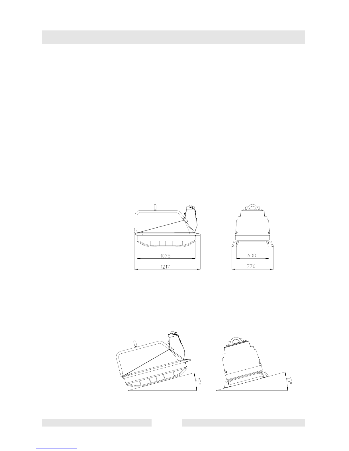
4.2 Dimensions
Description
The vibratory plate is excellently suited for the compaction of most
types of soils, including semi-cohesive soils, both in trench and in
surface compaction operations, as well as for the vibrating of heavy
interlocking concrete blocks or paving stones.
4.3 Max. admissible inclination
T01042GB 11
Page 14
Description
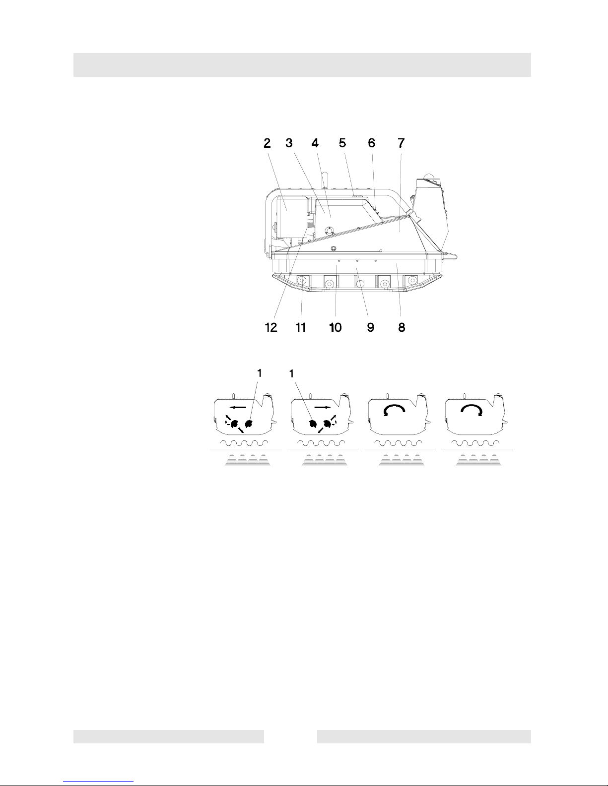
4.4 Description of function
Advance
The vibrationneededforthesoilcompactionisgenerated in the exciter
(9). The exciter is tightly bolted to the lower mass (8). It has been
designed as a central exciter, therefore allowing - by ways of a relative
rotationbetweentheexcentricweights(1)- the rotation of the direction
of the vibrations. Thanks to this technique, it becomes possible to
changeoverfromforwardtravelto a right or leftturnortoreverse travel
of the vibratory plate while during the compaction operation. This
process is controlled by means of a set of electro-hydraulic switching
valves.
The drive engine (12) anchored to the upper mass (7) drives the
exciter (9). The torque is transmitted by means of a friction connection
through the centrifugal clutch (4) and the exciter V-belt (10).
The centrifugal clutch interrupts flow of power to the exciter at low
engine speeds and thus permits perfect idling of the drive engine.
T01042GB 12
Reverse Left turn Right turn
Page 15

Description
The automatic V-belt pulley (3) combined with the centrifugal clutch
ensures optimum tension of the exciter V-belt during operation and
relief of the tension of the exciter V-belt when the machine is being
relocated or transported.
Moreover, the automatic V-belt pulley (3) automatically adapts to the
V-belt flanks in line with the wear and thus makes the entire drive from
the engine (12) to the exciter (9) maintenance-free.
The upper (7) and lower (8) masses are connected to each other by 4
vibration-damping shock mounts (11). This damping system prevents
the veryhighfrequenciesfrombeingtransmittedtotheupper mass. As
a result the functionability of the drive engine is retained in spite of the
high compaction performance.
The drive engine works on the diesel principle; it is started electrically
by a pinion starter (5), draws in the combustion air through an air filter,
dry (2) and is air-colled.
The machine is equipped with a fully electronic anti-restart delay
module that prevents any malfunction with consequential damages.
Always start and stop the machine from the remote control panel. To
facilitate the starting procedure (at very low temperatures) the drive
engine has an automatic decompression mechanism.
T01042GB 13
Page 16

Description
4.5 Infrared remote control
Always keep operating elements dry, clean and free of oil or grease.
Above all do not cover receiver or transmitter (remote control) under
any circumstances.
The machine can be operated only with a remote controller.
c
d
Operational elements – Machine
a
console:
a = Receiver eye with cover
b
b = LED-Ring
c = Oil warning lamp
f
d = Button ”I” – to activate the
e
machine
e = Button ”0” – to shut down the
maschine
f = Charge control lamp
r
g
o
l
k
m
Operational elements – Sender:
g = Joysticks – for moving and steering the machine
h = Rocker switch – for switching the sender on and off
i = Starter button – for starting the machine
k = LED green – battery charging (only during cable mode) – continuous illumi
nation
l = LED red – battery is empty, defective, or not in place - blinking
m = LED green – functional control lamp – regular blinking during send mode
n = LED red – warning when battery discharging – continuous illumination
o = Status LED green – blinks briefly with every actuation of a control element
(acknowledgement signal)
p = Chargingsocket – forconnectingthe spiral cablewhenoperating the sender
with an empty battery with automatic recharging of the battery for up to 40
minutes.
r = Neck strap – with integrated tear-off protection
s = Battery (exchangeable)
ni
p
g
h
s
T01042GB 14
Page 17

4.6 Charging the battery
There are two ways to charge the battery:
1. Spiral cable
Through the spiral cable (in the machine console) with the option of
operating the machine at the same time. Charging time maximum
40 minutes.
Green LED (k) on the sender will extinguish when the battery is
Description
recharged.
2. External charging device
Plug the external charging device into a 230-V socket – green LED
(t) illuminates if there is voltage. Insert and lock the battery (s).
Yellow LED (u) illuminates: Battery charges.
Yellow LED (u) blinks: Battery is charged.
t
u
s
To avoid downtime, we recommend keeping a replacement battery
ready in the charging station so that you can replace the operational
battery when it is empty.
T01042GB 15
Page 18

Description
4.7 Changing the transmission channel
You can set the sending channel in the sender and on the decoder on
the switch (v).
To change the channel on the sender, open the sender and move it to
one of the three possible positions..
v
The decoder must be set to the same channel as the transmitter.
After setting the desired channel, check the setting by switching on the
vibratory plate and the sender (see ”Activating the Machine”) – if the
channel selections match, the LED ring (b) on the receiver eye will
begin blinking.
4.8 Safety functions
To enhance the safety of the operator, the machine is equipped with a
function that automatically ceases all dangerous movements as soon
as the operator comes too close to the moving machine. All functions
are reactivated when the operator leaves the safety zone.
v
T01042GB 16
Page 19

Transport to work site /Recom-
5. Transport to work site /Recommendations on compaction
5.1 Transport to work site
Conditions:
∗ To transport the vibration plate, only use suitable lifting equipment with
a minimum load-bearing capacity of 700 kg.
∗ Always switch off engine before transporting the machine!
∗ Only attach suitable tackle at the central lifting point (13) provided.
∗ During transport on the loading area of a vehicle, tie down the vibraion
plate using the lugs (14).
Hote: Also overve the regulations in “safety instructions“.
T01043GB 17
Page 20

Transport to work site /Recommendations on compaction
5.2 Recommendations on compaction
5.2.1 Ground conditions
The max. compaction depth depends on several factors relating to the
ground condition, such as moisture, grain distribution etc,
it is therefore not possible to specify exact values.
Recommendation: In each case determine the max. compaction
depth with compaction tests and soil samples.
5.2.1 Compaction on slopes
The following points are to be observed when compacting on sloped
surfaces (slopes, embankments):
∗ Only approach gradients from the bottom (a gradient which can be
easily overcome upwards, can also be compacted downwards without
any risk).
∗ The operator must never stand in the direction of descent (see chapter
“safety instructions“).
o
∗ The max. gradient of 15
must not be exceeded.
If this gradient were exceeded, this would result in a failure of the
engine lubrication system and thus inevitably lead to a breakdown of
important engine components.
T01043GB 18
Wrong !
Right !
Page 21

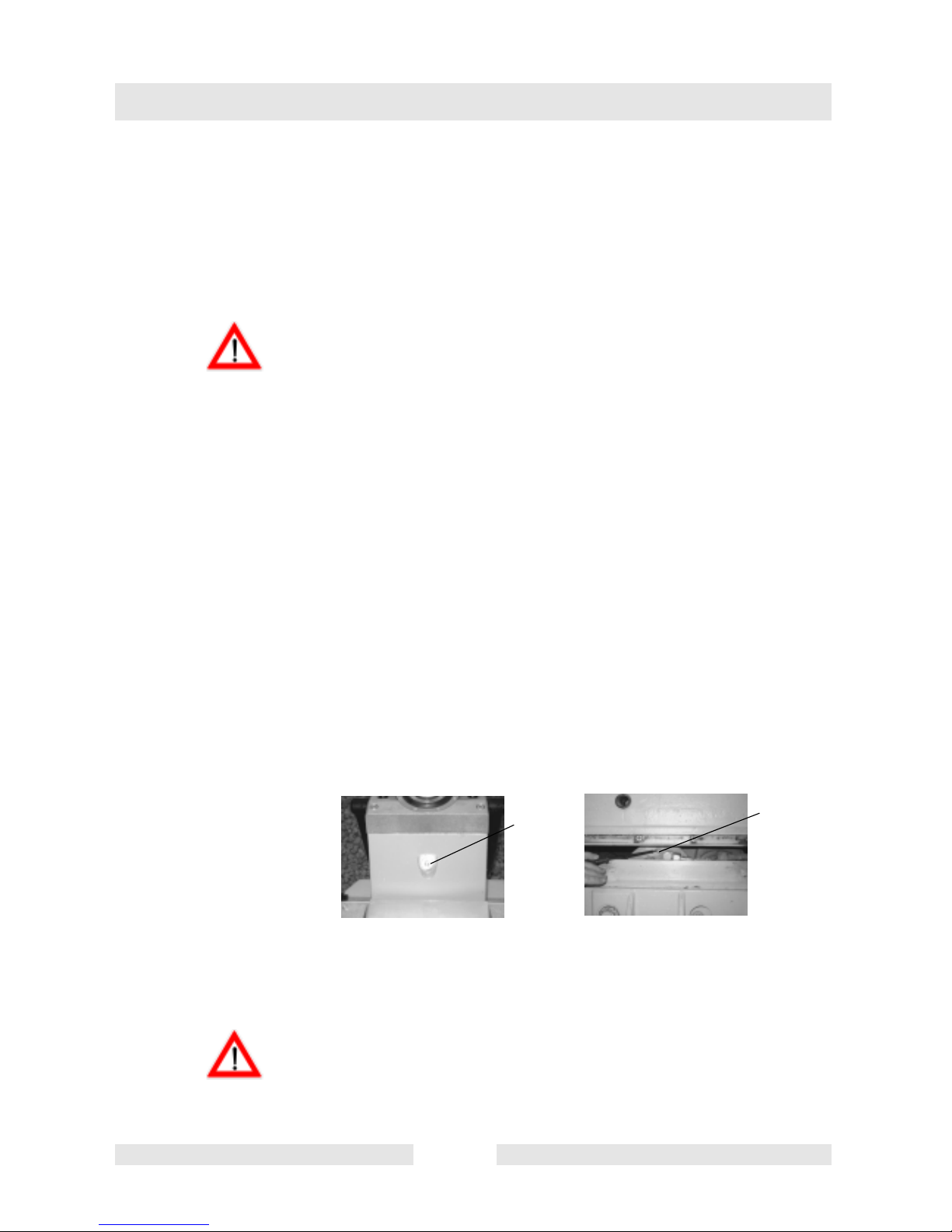
6. Operation
6.1 Conditions for starting
Engine oil:
Check oil level with dip stick (15) and replenish with oil through filler
neck (16) if necessary (see Technical Data).
The machine must be level and the engine stopped before proceeding
with the oil level check.
Fuel:
When pouring diesel fuel into the fuel nozzle (17), maintain absolute
cleanliness. Impurities in the fuel can cause breakdowns in the
injection system and premature clogging of the fuel filter.
Operation
15
16
17
Only refuel the machine when it’s engine is stopped.
Never refuel the machine close to open flames or ignitable sparks and
do not smoke.
Only use pure, clean fuel and clean filling vessels.
Do not spill any fuel.
Air filter:
Dry clean air filter dry, dusty conditions.
T01044GB 19
Page 22

Operation
6.2 Activating the machine
1. Machine console
Press the ”I” button foratleastonesecond–theyellowLEDring(b)
will illuminate.
2. Sender
Move the rocker switch (h) forward to ”I” – the green LED (m) starts
blinking regularly.
b
a
m
3. Point the sender at the receiver eye (a) on the machine – the yellow
LED ring (b) blinks.
LED ring (b) blinks slowly: All functions are activated.
LED ring (b) blinks rapidly: The operator is located in the machine’s
safety zone; all of the machine’s movements are deactivated.
Charge the transmitter’s rechargeable battery daily, at the latest
after the end of the working day, in the external battery charger.
The transmitter’s rechargeable battery can remain in the battery
charger for an unlimited period of time.
In accordance to the law the operators working place is at the rear end
of the machine.
An analogous inversion of the travel and steering direction can take
place if the operator is located in a position different to the designed
working position.
T01044GB 20
Page 23

6.3 Starting
1. Leave the machine’s safety zone.
2. Point the sender toward the receiver eye (a).
3. Hold the starter button (i) depressed until the vibratory plate runs.
4. The motor will automatically assume the standard speed when at
Operation
least one of the two joysticks (g) is moved from the center position.
a
g
i
g
Wait until the engine stops before repeating the starting procedure.
Only start upthe engine with a connected battery, so as to avoid
damages to the dynamo. Disconnect the negative pole when carrying
out welding jobs.
T01044GB 21
Page 24

Operation
6.4 Steering the machine
The operator determines the machine’s direction of travel by moving
the two joysticks (g) on thesender.Thevibratoryplatewillcompactthe
ground while moving forward, moving in reverse, spinning to the left,
spinning to the right, or simply standing still.
Advance
Push both joysticks
forward
Standing Still
The machine motor idles while both joysticks are in the
center position simultaneously for more than one second.
Reverse
Pull both joysticks
to the rear
Left turn
Pull the left joystick
to the rear,pushthe
ri ight joystick
forward
Right turn
Pushtheleftjoystick
forward, pull the
right joystick to
the rear
T01044GB 22
Page 25

6.5 Turning off engine
Sender:
1. Let go of both joysticks (g).
2. Switch off the sender by moving the rocker switch (h) from the ”I”
position to the ”0” position – green LED (m) extinguishes. LEDs (n
+ o) illuminate brieflyf
Operation
g
o
m
n
g
h
Machine Console:
1. Press ”0” button (e) for at least one second.
2. LED ring (b) extinguishes. Vibratory plate is no longer ready to
receive signals.
Note: If a worker forgets to turn off the machine at the end of the day, the
machine will switch itself off after 58 minutes..
b
6.6 Compaction without extension plates
If the vibration plates is used without extension plates, screw set of
protective screws (8 pes) into the threaded boreholes situated in the
lower mass, in order to avoid threads from being damaged.
T01044GB 23
e
Page 26

Operation
6.7 External starting
Observe the following connection sequence when using an external battery
to start the engine:
1. Stop engine.
2. In the first place connect the red battery jumper cable to the positive
3. In the second place connect the black cable to the negative pole of
Only 12 V batteries may be used. The use of e.g. a 24 V truck battery
will lead to an explosion of the vibro plate battery!
Only use insulated jumper cables!
pole of the dead battery and then connect the other end to the
positive pole of the charged battery.
the charged battery and only then connect the other end to the
negative pole of the dead battery.
4. Start the engine (max. 15 seconds) and then let the engine run.
5. Proceed in inverse order to disconnect the jumper cable.
6.8 Additional notes on starting at very low temperatures!
Never use starting sprays or similar - they are forbidden because they
are dangerous.
6.9 When there is danger of frost
After cleaning with water or a steam jet, run the machine to warm it
before shutting it down.
T01044GB 24
Page 27

7. Maintenance
7.1 Maintenance schedule
Check all external screw connections for tight fit appox. 8 hours alfter first operation.
Component Maintenance work Maintenance interval
Maintenance
Valve clearance Check, set to 0,1 mm when engine is cold.
Drive engine First oil change and filter.
Air filter Check - clean or replace if necessary.
Drive engine Check oil level - top up if necessary.
Control panel Check oil level - top up if necessar.
Check fastening screws of protecting frame for
frametight fit.
V-belt Check V-belt, if. nec. replace.
Drive engine Changing the oil and oil filter.
Exciter Check oil level, top up if necessary.
Exciter Oil change
Control panel Exchange the suction filter. every 250 h
Injection nozzle
Functioning check 175 bar, adjust if repair or
replace.
approx. 20 hours after
initial start-up
25 hours after initial
start-up
daily
monthlyProtective
every 150 h
every 250 h, or latest
every 6 months
Drive engine Retighten all accessible screw connections.
Battery
Valve clearance Check, set to 0,1 mm when engine is cold.
Drive engine
T01051GB 25
Check acidlevel -top up withdistilled waterifneces-
sary.
Fuel - change filter. every 500 h
Take engine to Wacker service station for
inspection.
every 300 h
every 2000 h
Page 28

Maintenance
7.2 Motoröl
∗ Check oil level on oil dipstick (15).
∗ Fill up with oil through the filler neck (16) if the oil level is too low (see
Check oil level:
Technical Data).
15
16
Engine shuts down automatically with low oil level!
∗
Changing the oil:
1. Let engine warm up.
2. Undo drain screw (24) and drain off oil.
3. Insert drain screw.
4. Pour in 2,1 l of oil through the filler nozzle (16)..
24
Take notice: Please pay attention to the corresponding environmental
rules and regulations when disposing of used engine oil. We
recommend you carry the oil in a closed container to a central
collecting point for used oils. Do not pour used engine oil into the
garbage nor into the sewer system, drains or even on the ground.
T01051GB 26
Page 29
Maintenance
7.3 Batterie
Check acid level:
1. Remove battery cover.
2. Check acid level, if necessary top up with distilled water.
3. Secure battery cover.
Beforemountingthebatterycover,make sure that the positiveterminal
cover is there!
Note: Only replace defective batteries with original Wacker batteries.
Standard batteries are not suitable for the high vibration loads.
4. When changing the battery:
Removal: First disconnect negativ, then positive terminal of battery.
Assembly: First connect positive, then negative terminal of battery.
When using starting sprays etc., see chapter operation.
7.4 Hydrauliksteuerung
Check oil level:
1. Open filler bore (25).
2. Oil level to lower edge of filler bore, fill up with hydraulic fuel if
necessary (see Technical Data).
3. Close filler bore (25).
Venting hydraulic control:
The system is bleeded by means of a M4 (27) screw situated on the
pump housing (below the rubber apron).
Check the reverse travel overrun when switching from reverse to
advance travel mode after having carried out maintenance or repair
jobs.Thereversetraveloverrunshould not exceed 10 cm. Ifnecessary
check hydraulic pressure (35 + 5 bar) and flow rate (2 liters per
second).
2
27
T01051GB 27
Page 30

Maintenance
7.5 Exciter
Lower end of thread
Check oil level:
1. Position vibration plate horizontally.
2. Open filler bore (28).
3. The oil level must reach the start of the thread of the filler bore.
4. Fill with oil throughfillerboreifnecessary (see Technical Data). Use
a suitable funnel.
5. Close filler bore. (Tightening torque100 Nm)
Changing the oil:
1. Remove extension plates if necessary.
2. Open filler bore.
3. Tilt vibration plate and keep it tilted until the oil has run out.
4. Place vibration plate in horizontal position.
5. Fill oil through filler bore (see Technical Data).
6. Close filler bore (28).
7. Mount extension plates if necessary.
(Tightening torque100 Nm)
Do not pour in too much oil!
Take notice: Please pay attention to the corresponding environmental
rules and regulations when disposing of used engine oil. We
recommend you carry the oil in a closed container to a central
collecting point for used oils. Do not pour used engine oil into the
garbage nor into the sewer system, drains or even on the ground.
T01051GB 28
Page 31

7.6 Assembly instruction
Before removing the individual parts of the exciter assembly, the
eccentric weights must be unbolted and taken off. During assembly,
the eccentric weights must be put in place last of all. When fitting the
exciter shafts, pay attention to the marks on the gears. The shafts will
have been correctly assembled, if, after having ceased swinging and
coming to a standstill, they are pointing to the rear and in a 45
towards thebottom. (Note: Theopenendoftheexciterisupwards,the
Wacker lettering is to the rear). Tighten all screws with the prescribed
torque, while minding the quality of the screws (see screw heads).
When disassembling the actuating pins, keep in mind that the pistons
are under spring tension.
7.7 Exciter V-belt
It is not necessary to retighten the V-belt owing to the use of the
automatic centrifugal clutch.
Changing the exciter V-belt:
Maintenance
o
angle
1. Take off small part of engine cover.
2. Take off interior aluminum protective frame.
3. Undo screw (29).
4. Remove button (30), belleville spring (31), seal (32) and front
segment of the V-belt pulley (3).
5. Change exciter V-belt (10).
6. Assemble the components in reverse order; make sure that the
coloured marking on the pin (33) coincides with the marking on the
V-belt pulley (3).
Do not oil or grease clutch components (will damage the glide
bushings).
T01051GB 29
Page 32

Faults
8. Faults
8.1 Disturbance on the machine console
c
d
b
f
e
Pressing the ”I” (d) button does not activate the machine – LED ring (b)
does not illuminate
Cause Remedy
The vibratory plate’s on-board battery
is discharged.
Button defective.
Button has no electrical contact. Check connection and repair.
LED ring has no electrical contact. Check connection and repair.
Charge the battery and check the
functionality of the charge regulator if
necessary.
Replace the button with an original
replacement part.
The charge control lamp (f) does not extinguish while motor is running
Cause Remedy
The on-board battery is not receiving a
charge.
Regulator or alternator is defective.
The oil control lamp (c) does not extinguish while motor is running
Cause Remedy
Engine oil level too low. Fill up with engine oil.
Oil pressure switch defective.
Oil pressure switch has no electrical
contact.
T01052GB 30
Check the relevant connections or
ask Wacker service for assistance.
Replace the regulator or ask Wacker
service for assistance.
Replace the oil pressure switch with
an original replacement part.
Check connection and repair.
Page 33

Faults
Pressing the ”0” button (e) does not shut down the machine – LED ring
(b) stays illuminated
Cause Remedy
Button defective.
Button has no electrical contact.
8.2 Disturbance on sender
The sender LED (m) does not start blinking when the rocker switch (h)
is in the ”I” position
Cause Remedy
Sender battery is discharged.
Replace the button with an original
replacement part.
Check connection and repair.
b
m
Replace battery with charged battery.
Operate the machine with the spiral
cable attached, automatically cha ging
the battery.
h
i
Sender defective.
LED ring (b) illuminates but does not blink, although the machine is
switched on and an activated sender is pointed at the receiver eye
Cause Remedy
Sender and receiver not using the same
channel.
LED ring (b) blinks but the machine does not react to the starter button
(i)
Cause Remedy
Starter damaged or connection defetive.
The vibratory plate’s on-board battery is
largely discharged.
T01052GB 31
Contact Wacker service dept.
Open sender, set proper channel.
Contact Wacker service dept.
Charge the battery and check the
functionality of the charge regulator
if necessary.
Page 34

Faults
The machine can be started, but does not move – LED ring (b) blinks
rapidly
Cause Remedy
The operator is standing in the
machine’s safety zone.
8.3 Forward speed too low
Cause Remedy
To little hydraulic oil in the centre pole
head.
Air in hydraulic control. Bleed system.
8.4 No reverse motion
Operator must leave the safety zone.
Top up hydraulic oil.
Cause Remedy
Mechanical fault. Contact Wacker service dept.
8.5 Loss of hydraulic oil
Cause Remedy
Leaks, hydraulic hose defective.
Contact the Wacker Service in case of additional failures.
T01052GB 32
Change defective parts.
Note: Bleed system after every
dismantling operation.
Page 35

Electricwirning-Diagramm
SK00689GB 33
9. Electricwirning-Diagramm
PlugA, grey
A1 Ground, brown
A2 +12V ON, pink
A3 STA OUT, black
A4 FUE OUT, lilac
A5 CTL OUT, brown
A6 12V MF, red
A7 12V MF, red
A8 Ground, brown
A9 Eye specifications, blue
A10 Eye+, pink
A11 Ground, blau
A12 +12V OUT, red
Plug B, black
B1 GV 1 OUT, black
B2 R OUT, lilac
B3 L OUT, blue
B4 GV 2 OUT, red
B5 OELDR IN, white
B6 OFF IN, red
B7 FREQ IN, black
B8 POS IN,
B9 GND, brown
B10 GND, brown
B11 GND, brown
B12 GND, black
Console
Generator
Electric starter
Battery
Diesel valve
Left
Eccentric
weight
Throttle adjuster
Charge regulator
Oil pressure
lamp
ONSwitch
LED-Ring
Oil pressure switch
Plug A
grey
Plug B
black
Codification
switch
IR - Receiver
Right
Eccentric
weight
Charge socket
Decoder
Charge control lamp
Generator
Generator
black
red
black
red/yellow
yellow
ayellow
redrred
brown
white
brown
red/yellow
pink
red
pink
white
black
red
red
pink
OFFSwitch
black
Page 36

Lables
10. Lables
1 Notice-Lifting point
2 Notice-Oil level indication
3 Sound power level
4 Ear protection decal
5 Warning notice
- Do not run without protective devices.
- Read operator’s manual in detail.
6 Type
7 Wacker Logo
SK00690GB 34
Page 37

EC - Conformity Certificate
Wacker Construction Equipment AG , Preußenstraße 41, 80809 München
hereby certify that the construction equipment specified hereunder:
1. Category:
Vibratory plate
2. Type:
DPU 7060SC
3. Equipment item number:
0008927
4. Absolute installed power:
10,5 kW
has been evaluated in conformity with Directive 2000/14/EC:
Conformity assessment
procedure
Annex VIII VDE Prüf- und
At the following notified
body
Zertifizierungsinstitut
Zertifizierungsstelle
Merianstraße 28
63069 Offenbach/Main
Measured sound
power level
107 dB(A) 109 dB(A)
Guaranteed sound
power level
and has been manufactured in accordance with the following directives:
* 2000/14/EG
* 89/336/EG
* 98/37/EG
* 73/23/EG
EN 500-1
EN 500-4
File certificate carefully
C0008807GB
Dr. Stenzel
Research and Development Management
Page 38

Page 39

Prüf- und Zertifizierungsinstitut
VERBAND DER ELEKTROTECHNIK
ELEKTRONIK INFORMATIONSTECHNIK e.V.
C E R T I F I C A T E
Registration-Number: 6236/QM/06.97
This is to certify that the company
Wacker Construction Equipment AG
Wacker-Werke GmbH & Co. KG
at the following locations
Head Office Munich
Preußenstraße 41
80809 Munich
Production plant Reichertshofen
Karlsfeld logistics centre
Sales regions with all branches all over Germany
has implemented and maintains a
Qality Management System for the following scope:
Machine manufacture
Construction machines
This Q System complies with the requirements of
DIN EN ISO 9001:2000
and the requirements of the German and international Road Traffic Act.
This Certificate is valid until 2009-06-05.
VDE Testing and Certification Institute
Certification
Date: 2003-05-30
63069 Offenbach, Merianstraße 28
Telefon: +49 (0) 69 83 06-0, Telefax: +49 (0) 69 83 06-555
E-Mail: vde-institut@vde.com
, http://www.vde-institut.com
The VDE Testing and Certification Institute is accredited by DAR Accreditation
Bodies according to DIN EN ISO 17020 and DIN EN ISO 45012 and notified in the EU
under ID.No. 0366.
TGA-ZM-09-92-00
KBA-ZM-A 00021-97
DIN EN ISO 9001 Certificate
Page 40

Wacker Construction Equipment AG - Preußenstraße 41 - 80809München - Tel.: +49-(0)89-354 02-0 - Fax:+49-(0)89-3 54 02-390
WackerCorporation - P.O. Box9007 - MenomoneeFalls, WI 53052-9007 - Tel.: +1-(1)(262)-255-0500 - Fax: +1-(1)(262)-255-0550 - Tel.: (800)770-0957
Wacker Asia PacificOperations-SkylineTower, Suite 2303,23/F,39 Wang KwongRoad,Kowloon Bay, HongKong-Tel.:+852 2406 6032-Fax:+852 2406 6021
Page 41

Page 42

 Loading...