

Page 1

www.wackergroup.com
Operator´s Manual
VIBRATORY PLATE
DPU 6055
0200303en - 12.2001
0008766 100
0008768 100
Page 2

Page 3

H00553GB
1
CONTENTS
Type Item no.
DPU 6055 0008766 ...
DPU 6055 - 860 wide 0008768 ...
This machine has been equipped with an EPA certified engine.
Additional information can be found in the engine manufacturers notes.
Page 4

2
Page 5

T00778GB
3
FOREWORD
Foreword
For your own safety and protection from bodily injuries, carefully read, understand and follow the safety instructions in this manual.
Please operate and maintain your Wacker machine in accordance with the instructions in this manual. Your
Wacker machine will reward your attention by giving trouble-free operation and a high degree of availability.
Defective machine parts are to be replaced as soon as possible. You will find the spare part required by you
and the relevant item number in the chapter "Spare part lists" in this instruction book.
All rights, especially the right for copying and distribution are reserved
Copyright by Wacker-Werke GmbH & Co. KG
No part of this publication maybe reproduced in any form or by anymeans, electronic or mechanical, including
photocopying, without express permission in writing from Wacker-Werke GmbH & Co. KG.
Any typeofreproduction,distributionorsavingondata carriers of any type or method not authorized by Wacker
represents an infringement of valid copyrights and will be prosecuted.
We expressly reserve the right to technical modifications- even without express due notice - which aim at improving our machines or their safety standards.
Page 6

0127308GBIVZ.GB.fm
4
TABLE OF CONTENTS
FOREWORD 3
SAFETY INSTRUCTIONS 6
General instructions 6
Operation 6
Safety checks 7
Maintenance 7
Transport 7
Maintenance checks 7
TECHNICAL DATA 8
DESCRIPTION 10
Field of application 10
Dimensions 10
Max. admissible inclination 10
Description of function 11
TRANSPORT TO WORK SITE, RECOMMENDATIONS ON COMPACTION 13
Transport to work site 13
Recommendations on compaction 13
OPERATION 14
Starting requirements 14
Electric start 16
Starting the engine with the safety starting crank 18
Starting in cold weather 21
Starting with external battery etc. 23
Forward and reverse motion 23
Compaction without extension plates 24
Stopping the engine 24
MAINTENANCE 25
Maintenance schedule 25
Engine oil and oil filter 26
Air filter 28
Fuel system 30
Battery 31
Hydraulic control 31
Exciter 32
Exciter V-belt 32
FAULTS 33
Forward speed too low 33
Reverse speed too low 33
No reverse motion 33
Loss of hydraulic oil 33
The charge control lamp will not extinguish and/or the buzzer will not stop buzzing 33
Engine does not start 33
ACCESSORIES 34
Page 7

0127308GBIVZ.GB.fm
5
TABLE OF CONTENTS
EC - CONFORMITY-CERTIFICATE 37
Page 8

SV00006GB
6
SAFETY INSTRUCTIONS
SAFETY INSTRUCTIONS FOR THE USE OF VIBRATORY
PLATES WITH COMBUSTION ENGINES
General instructions
1. Vibratory plates may only be operated by persons who
* are at least 18 years of age
* are physically and mentally fit for this job
* have been instructed in guiding vibratory plates and proved their ability for the job to the employer
* may be expected to carry out the job they are charged with carefully.
The persons must be assigned the job of guiding vibratory plates by the employer.
2. Vibratory plates may only be used for compaction jobs. Both the manufacturer’s operating instructions
and these safety instructions have to be observed.
3. The persons charged with the operation of vibratory plates have to be made familiar with the necessary
safety measures relating to the machine. In case of extraordinary uses the employer shall give the necessary additional instructions.
4. It is possible that this vibratory plate exceeds the admissible sound level of 89 dB (A). According to the
rules for the prevention of accidents regarding emission of noise, the employees have to wear ear protection if the sound level reaches 89 dB (A) or more.
Operation
1. When starting a diesel engine with a starter crank make sure you have assumed a proper position with
respect to the engine and that your hands are placed properly on the crank.
☛ATTENTION! Only use the original engine manufacturer’s safety starting crank.
To avoid a possible return kick, turn safety starting crank through with full force until
the engine starts running.
2. The functioning of operating levers or elements is not to be influenced or rendered ineffective.
3. During operation the operator may not leave the control elements.
4. The operator has to stop the engine of the vibratory plate before going on breaks. The machine has to
be placed such that it cannot turn over.
5. Stop engine before filling fuel tank. When refilling fuel tank, do not allow fuel to come into contact with
the hot parts of the engine or spill onto the ground.
6. Do not smoke or handle open fire near this machine.
7. The tank lid must fit tightly. Shut off fuel cock, if available when stopping the engine. For long distance
transports of machine operated by fuel or fuel - mixtures, the fuel tank has to be drained completely.
☛ATTENTION! Leaky fuel tanks may cause explosions and must therefore be replaced immediately.
8. Do not operate the machine in areas where explosions may occur.
9. Make sure that sufficient fresh air is available when operating vibratory plates with combustion engines
in enclosed areas, tunnels, adits and deep trenches.
10. During operation keep your hands, feet and clothes away from the moving parts of the vibraton plate.
Wear safety shoes, and eye protection glasses in case of trench operation where falling sand stones
maybe ejected.
11. When working near the edges of breaks, pits, slopes, trenches and platforms, vibratory plates are to be
operated such that there is no danger of their turning over or dropping in.
Page 9

SV00006GB
7
SAFETY INSTRUCTIONS
12. Make sure the soil or subsoil to be compacted has a high enough load carrying capacity.
13. Use appropriate protective clothing while working or while carrying out maintenance work.
14. When traveling backwards the operator has to guide the vibration plate laterally by its guide handle so
thathewillnotbesqueezedbetweenthehandleandapossibleobstacle.Specialcareisrequiredwhenwork
ing on uneven ground or when compacting coarse material. Make sure of a firm stand when operating
the machine under such conditons.
15. Vibratory plates are to be guided such that hand injuries caused by solid objects are avoided.
16. Vibratory plates have to be guided such that their stability is guaranteed.
17. Machines with integrated transport trolley may not be parked or stored on the trolley. This device has
only been designed to transport the machine.
Safety checks
1. Vibratory plates may only be operated with all safety devices installed.
2. Before starting operation, the operator has to check thatall control andsafety devices function properly.
3. Immediately notify your supervisor or superintendent if you have determined defects in the safety devices or other defects which could endanger the safe operation of the machine or which could endanger
the environment.
4. In case of defects jeopardizing the operational safety of the vibration plate, the machine has to be
stopped immediately.
5. Process materials and operating fuels must be stowed away in receptacles or containers marked according to the respective manufacturers specifications.
Maintenance
1. Only use original spare parts. Modifications to this machine, including the adjustment of the maximum
engine speed set by the manufacturer, are subject to the express approval of Wacker. In case of nonobservance all liabilities shall be refused.
2. All drive units have to be switched off before carrying out maintenance jobs. Deviations from this are only
allowed if the maintenance or jobs require a running engine.
3. When working on vibratory plates equipped with electric starter, disconnect battery before carrying out
maintenance or repair jobs on the electric parts of the machine.
4. Remove pressure from hydraulic lines before working on them. Caution: take care when removing hydraulic lines, for the oil may be very hot (up. over 80oC). Precautions are to be taken to prevent oil from
splashing into the operator’s eyes.
5. As soon as maintenance and repair jobs have been completed all safety devices have to be reinstalled
properly.
6. Do not hose down the machine with water after each use to avoid possible malfunctions. Do not use high
pressure washers nor chemical products.
Transport
1. During transport, loading and unloading ofvibration platesby meansof lifting devices, appropriate slinging means or hooks have to beused onthe lifting pointsprovided forthis purpose onthe vibratoryplate.
2. The load-carrying capacity of the loading ramps has to be sufficient and the ramps have to be secure
such that they cannot turn over. Make surethat noone be endangeredby machines turningover by slipping or by moving machine parts.
3. When being transported on vehicles, precautions have to be taken that vibration plates do not slip or turn
over.
Maintenance checks
According to the conditions and frequency of use, vibratory plates have to be checked for safe operation at
least once a year by skilled technicians, such as those found at Wacker-service depots and have to be repaired
if necessary.
Please also observe the corresponding rules and regulations valid in your country.
Page 10

TD00553GB
8
TECHNICAL DATA
DPU 6055 DPU 6055 - 860 wide
Item no. 0008766 ... 0008768 ...
Operating weight
without extension plates (550) kg: 455
with extension plates narrow (610) kg: 471
with extension plates Serial (710) kg: 478
with extension plates wide (860) kg: 497
Power transmission From drive engine directly to exciter
unit via automatic centrifugal
and V-belts
Exciter
Vibrations min-1(Hz): approx. 4150 (69)
Multigrade oil SAE 10W-40
Drive motor Air-colled single-cylinder 4 stroke
diesel engine - with electric starter
Piston displacement cm3: 667
Rated power kW: 9,7
at rpm min-1: 2650
Operating rpm’s min-1: 2880
No-load rpm’s min-1: 2950
Oil SAE 10W-40
Fuel Diesel
Fuel consumption l/h: 2,2
Tank capacity l: 7,0
Electrical system
Battery Special Wacker-battery for
vibro plates, 12 V - 55 Ah
Alternator Rotary current generator with
electronic regulator and rectifier
Charging rate max. A: 26
Charging voltage V: 14
Starter Starter motor
D.C. V: 12
Hydraulic control
Hydraulic oil Fuchs Renolin MR 520
Page 11

TD00553GB
9
TECHNICAL DATA
The required sound specifications, called-for by the EC-Machine Regulations per Appendix 1, Paragraph
1.7.4.f, are
- sound pressure level at the operator's location LpA = 97 dB(A)
The sound values were determined according to ISO 3744 for the sound power level (LwA) and, alternately,
ISO 6081 for the sound pressure level (LpA) at the operator's location.
The weighted effective acceleration value, determined according to ISO 8662, Part 1, is 7,6 m/s2.
The sound and vibration measurements were carried out and obtained with the machine working on crushed
gravel at nominal engine speed.
Page 12
T00781GB
10
DESCRIPTION
Field of application
The vibratory plate has been designed for the compaction of almost every type of soil, both in trenches as well
as surface compaction. In addition, it is possible to vibrate paving stones an concrete blocks by using extension
plates up to 86 cm (accessories).
Extremely cohesive as well as frozen soils are not suitable for compaction.
An authorised specialist must give permission for the ground in question to be compacted.
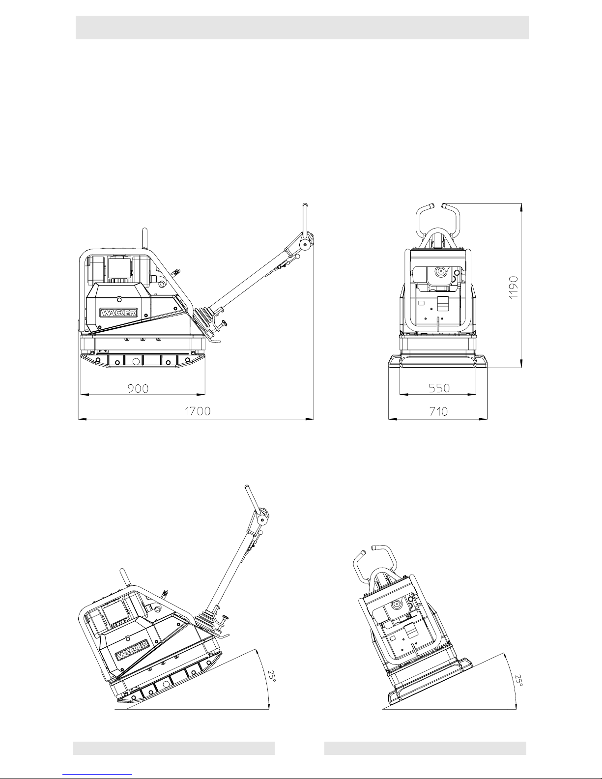
Dimensions
Max. admissible inclination
Page 13
T00781GB
11
DESCRIPTION
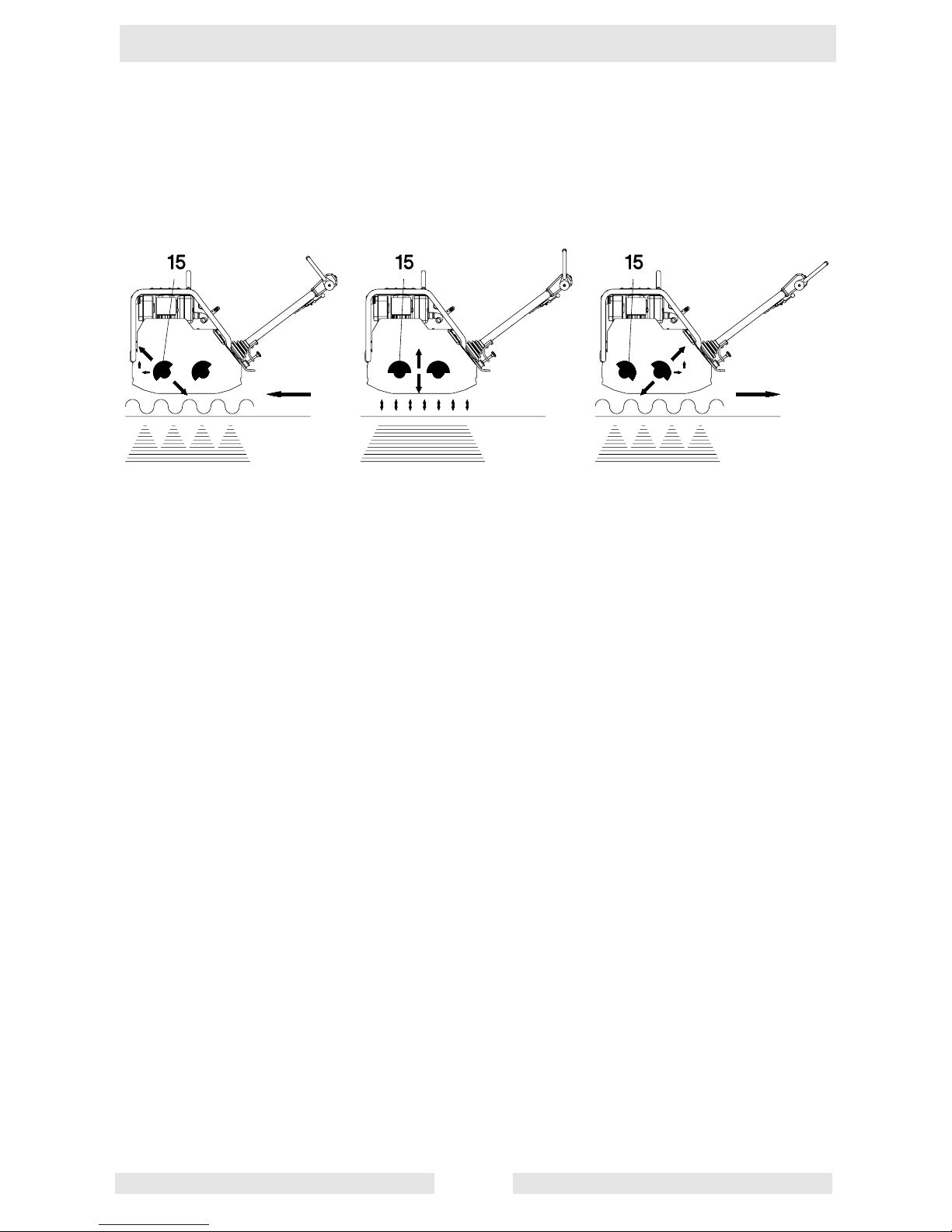
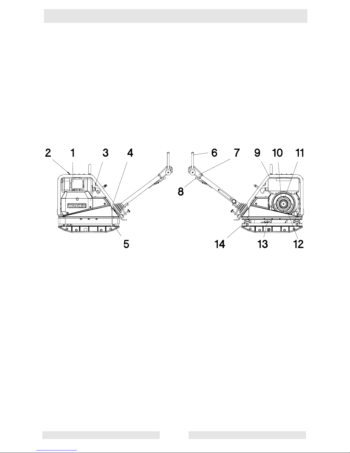
Description of function
The vibration required for compaction is produced by the exciter (13) which is firmly joined to the lower mass
(5). This exciter (13) is designed as a central vibrator with aligned vibrations. Such a principle permits the direction of vibration to be changed by turning the eccentric weights (15). In this way an infinitely variable transition between vibration in forward motion(Fig. 1),at standstill(Fig. 2)and inreverse motion(Fig. 3)is possible.
This process is hydraulically controlled with the operating control handle (6) on the centre pole head (7).
Forwards Standstill Reverse
The drive engine (1) anchored to the upper mass (4) drives the exciter (13). The torque is transmitted by means
of a friction connection through the centrifugal clutch (11) and the exciter V-belt (12).
The centrifugal clutch (11) interrupts flow of power to the exciter (13) at low engine speed and thus permits
perfect idling of the drive engine (1).
The automatic V-belt pulley (10) combined with the centrifugal clutch (11) ensures optimum tension of the exciter V-belt (12) during operation and relief of the tension of the exciter V-belt (12) when the machine is being
relocated or transported.
Moreover, the automatic V-belt pulley (10) automatically adapts to the V-belt flanks in line with the wear and
thus makes the entire drive from the engine (1) to the exciter (13) maintenance-free.
Page 14
T00781GB
12
DESCRIPTION
The speed of the drive engine (1) can be infinitely varied by remote control on the throttle control lever (8).
The upper (4) and lower (5) masses are connected to each other by 4 vibration-damping rubber metal shock
mounts (14). This damping system prevents the very high frequencies from being transmitted to the upper
mass (4). As a result the functionability of the drive engine (1) is retained in spite of the high compaction performance.
The drive engine (1) works on the diesel principle; it is started electrically by a pinion starter (3), draws in the
combustion air through an air filter, dry (9) and is air-colled.
To facilitate the starting procedure (at very low temperatures, with hand start) the drive engine (1) has an automatic decompression mechanism (2). It ensures that compression is very low during the cranking operation
but steadily increases after a few revolutions when it then switches over to full compression.
Page 15

T00782GB
13
TRANSPORT TO WORK SITE, RECOMMENDATIONS ON COMPACTION
Transport to work site
Conditions:
- To transport the vibration plate, only use suitable lifting equipment witha minimum load-bearing capacity of
500 kg.
- Always switch off engine before transporting the machine!
- Only attachsuitable tackle atthe centrallifting point(16) provided. Thecentral liftingpoint islocated exactly
above the centre of gravity of the machine. The central lifting point can be displaced rearwards (18), given
an application in which the height of the machine is of importance (torque wrench setting = 85 Nm).
- During transport on the loading area of a vehicle, tie down the vibration plate using the lugs (17).
Note: Also overve the regulations in safety instructions.
Recommendations on compaction
Ground conditions
The max. compaction depth depends on several factors relating to the ground condition, such as moisture,
grain distribution etc.
It is therefore not possible to specify exact.
Recommendation: In each case determine themax. compaction depth with compaction tests and soil sam-
ples.
Compaction on slopes
The following points are to be observed when compacting on sloped surfaces (slopes, embankments):
* Only approach gradients from the bottom (a gradient which can be easily overcome upwards, can also be
compacted downwards without any risk).
* The operator must never stand in the direction of descent (see chapter “safety instructions“).
* The max. gradient of 25omust not be exceeded.
☛ATTENTION! A tilt in excess of this angle could lead to a stopping of the engine due to the automatic
low oil shut-off system. A restarting of the engine can only take place after the valve lever
at the oil filter housing has been actuated once.
Right ! Wrong !
Page 16

T00796GB
14
OPERATION
Starting requirements
1. Engine oil
Check oil level on oil dipstick (19), if necessary top up with HD brand oil SAE 10 W-40 using the filler
nozzle (21).
☛ATTENTION! The machine must be level and the engine stopped before proceeding with the oil level
check.
2. Fuel
When pouring diesel fuel into the fuel nozzle (20), maintain absolute cleanliness. Impurities in the fuel can
cause breakdowns in the injection system and premature clogging of the fuel filter.
☛ATTENTION! - Only refuel the machine when it’s engine is stopped.
- Never refuel the machine close to open flames or ignitable sparks and do not smoke.
- Only use pure, clean fuel and clean filling vessels.
- Do not spill any fuel.
3. Mechanical oil pressure control
It is necessary to reactivate the mechanical oil pressure control in the following cases:
- after the initial filling - first filling - of the fuel tank or if the tank has run dry.
- in the case of an automatic engine stop due to an inefficient
engine oil supply.
- after freeing the engine when in presence of extremely low
temperatures.
1. Fill up fuel tank.
2. Check engine oil level.
3. To activate depress hand lever „d“ for approx. 5 seconds.
4. Check to see that the engine does not leak.
5. Start engine.
☛ATTENTION! Check oil level every 8 to 15 operatinghours inspite of themechanical oil pressurecon-
trol.
☛ATTENTION! - Never let the engine run in closed or badly aired spaces due to danger of poisoning!
- Before starting the engine always make sure that nobody is in the danger area of the
vibratory plate and also check to see if all the safety devices are installed.
- Never use starter sprays to start the engine.
d
Page 17

T00796GB
15
Page 18

T00796GB
16
OPERATION
Electric start
1. Turn the throttle control lever (8) clockwise into load position 1/2 - 3/4.
2. Leave decompression lever (2) in the position „e“.
3. Put the ignition key into ignition switch (25) and turn it clockwise into operating position (the charge control
lamp (27) lights up and the buzzer will be heard). Press in and hold the starter (26) until the engine has
started.
☛ATTENTION! Wait until the engine stops before repeating the starting procedure.
4. The charge control lamp (27) must turn off immediately after the engine has started running and the
acoustic alarm has stopped. Stop the engine immediately in case of eventual irregularities, then locate the
fault and repair it.
☛ATTENTION! The machine will start vibrating as soon as the engine starts revving up.
Note: Do not activate automatic decompression lever while the engine is running.
5. Bring the engine up to maximum rpm’s and then check the air filter’s service indicator (also see chapter on
„Maintenance“); clean the dry-type air filter if necessary.
f
e
Page 19

T00796GB
17
Page 20

T00796GB
18
OPERATION
Starting the engine with the safety starting crank
1. Turn the throttle control lever to the load position 1/2 - 3/4.
2. Turn the decompression lever (2) all the way to „f“.
At this point automatic decompression leverengages withan audibleclick, andthe engineis readyto start.
3. Put the ignition key into ignition switch (25) and turn it clockwise into operating position (the charge control
lamp (27) lights up and the buzzer will be heard).
4. ☛ATTENTION! Check to see that the safety starting crank is in good shape and clean!
Broken handle pipes, worn cranking bolts, etc. must be replaced!
Lightly grease the gliding area located between the safety starting crank and the guide
bush (protective casing).
- Stand sideways to the engine.
- Always grasp the handle pipe (h) with both hands.
f
e
Page 21

T00796GB
19
Page 22

T00796GB
20
OPERATION
- Slowly turn the safety starting crank counter-clockwise until the ratchet engages. Then start turning the
handle with force and with ever increasing speed. The highest possible turning speed must have been
reached when the decompression lever reaches position ”e” (compression).
Pull the safety start crank out of the protective hood once the engine has started.
☛ATTENTION! The friction (non-positive) connection between engine and safety starting crank must be
guaranteed by a firm grip onthe handle pipeand rapidturning of the crank and must not
be interrupted under any circumstances during the starting operation.
The connection between the crank web (g) and the crank claw will be released if - due to a hesitant turning
of the handle - a return kick should take place during the starting operation.
- Let loose of thesafety starting crank immediately and stop the engineif it shouldstart turning inthe wrong
direction (smoke coming from the air filter) after a back kick.
☛ATTENTION! Wait until the engine stops before repeating the starting procedure.
5. The charge control lamp (27) must turn off immediately after the engine has started running and the
acoustic alarm has stopped. Stop the engine immediately in case of eventual irregularities, then locate the
fault and repair it.
☛ATTENTION! The machine will start vibrating as soon as the engine starts revving up.
Note: Do not activate automatic decompression lever while the engine is running.
6. Bring the engine up to maximum rpm’s and then check the air filter’s service indicator (also see chapter on
„Maintenance“); clean the dry-type air filter if necessary.
h
g
i
Page 23

T00796GB
21
OPERATION
Starting in cold weather
Always free the engine if the temperature is less than -5 ˚C (23 ˚F).
1. Push the throttle lever (8) to the full throttle position.
2. Turn decompression lever to any position in front of starting position „f“.
3. Crank the engine counter-clockwise with the safety start crank (24) as long as necessary until cranking
becomes easier (10 to 20 crank turns).
4. Press pin „d“ in for approx. 5 seconds.
5. Clean the area around the dosing device and then pull off the cover.
6. Fill the housing to the upper edge with low viscosity oil. Replace cover and press down with force. Exactly
two successive fillings are required.
7. Turn the decompression lever all the way to „f“.
8. Then start the engine immediately with the electric starter or by using the safety start crank.
d
f
e
Page 24

T00796GB
22
Page 25

T00796GB
23
OPERATION
Starting with external battery etc.
Observe the following connection sequence when using an external battery to start the engine:
1. Connect one end of jumper cable to positive terminal of auxiliary battery.
2. Connect the other end of jumper cable to positive terminal of the vibro plate battery.
3. Now connect jumper cable clamp to negative terminal of the auxiliary battery.
4. The other end of the cable must be connected to the negative terminal of the vibratory plate’s battery.
5. Disconnect jumper cable in reserve order.
☛ATTENTION! Only 12 V batteries may be used. The use of e.g. a 24 V truck battery will lead to an
explosion of the vibro plate battery!
☛ATTENTION! Only use insulated jumper cables!
Forward and reverse motion
The engine speed can be infinitely varied on the throttle control lever (8).
The direction of travel is determinet with the shift lever (6).
Depending on the position of the shift lever (6), the vibration plate compacts in forward direction, at standstill
or in reverse direction.
The forward and reverse speeds can be varied by selecting intermediate positions of the shift lever (6) or the
machine can be employed for particularly intensive compaction at standstill.
Forwards Standstill Reverse
Page 26

T00796GB
24
OPERATION
Compaction without extension plates
If the vibration plates is used without extension plates, screw set of protective screws (8 pes) No. 0067519 into
the threaded boreholes situated in the lower mass, in order to avoid threads from being damaged.
Stopping the engine
☛ATTENTION! Never switch off the engine with the automatic decompression (2) as this inevitably results
in damage to the valve drive and decompression mechanism.
1. Move the throttle control lever (8) to the stop.
2. Turn the ignition key to the stop position and then pull it out once the engine has stopped. The control lamp
will extinguish and the acoustic alarm will turn off.
Page 27

T00797GB
25
MAINTENANCE
Maintenance schedule
Component Maintenance work Maintenance interval
External hardware Check for tightness. approx. 8 hours after
initial start-up
Drive engine First oil change and filter. 25 hours after initial
start-up
Machine cpl. Run a visual check to see that everything is daily
complete and undamaged.
Air filter Check area around combustion air intake and also
air filter service indicator.
Drive engine Check oil level, if nec. top up oil.
Centre pole height Regrease. weekly
setting, transport lock
Fuel tank Check water separator.
V-belt Check V-belt, if. nec. replace. monthly
Protective frame, Check attachment screws for tight fit.
central lifting point
Tow-bar head Check oil level, top up if necessary.
Exciter Oil change. every 250 h,
or latest every
6 months
Drive engine Oil change, change oil filter. every 250 h
Keep cooling fins free of dirt, clean dry.
Check accessible hardware.
Battery Check acid level, if nec. top up with distilled water.
Valve clearance Cold engine: Check valve clearance, and adjust
if necessary.
Inlet valve 0,1 mm - outlet valve 0,2 mm.
Fuel filter Change filter. every 500 h
Air filter Replace filter insert.
Fuel injector Clean, adjust if necessary, repair or replace. every 1500 h
Injector valve Clean, adjust or replace if necessary. every 3000 h
Page 28

T00797GB
26
MAINTENANCE
Engine oil and oil filter
Check oil level:
- Remove dirt from the oil dip stick area. Check oil level on oil dipstick (19).
☛ATTENTION! Place the machine in an horizontal (level) position and stop the engine before checking
the oil level.
- If the oil level is too low, top up with HD brand oil SAE 10W-40 though the filler nozzle (21).
- Pay attention to the max. level mark on the dip stick!
Replacing oil and oil filter:
1. Let engine warm up.
2. Take off the front cover plate.
3. Remove the oil hose from the support (spanner opening 19) and then hang the hose into an appropriate
container.
☛ATTENTION! Danger of scalding by hot oil!
Collect the used oil and dispose of it according to local regulations.
4. Let the oil drain completely. Lift the back end of the machine if necessary.
5. Replace oil filter.
6. Clean mesh insert carefully to avoid bending the wire netting.
☛ATTENTION! Watch out for the ”TOP” marking on the oil filter!
7. Check and, if necessary, replace O-ring „k“.
8. Moisten thread and O-ring of the screwed sealing plug with a lubricant.
9. Fill up with engine oil until the max. marking of the dip stick is reached.
10.Check the oil level again after a short engine test run and top up if necessary.
11.Be sure to check that the screwed sealing plug does not leak.
12.Fasten the front cover plate.
k
Page 29

T00797GB
27
Page 30

T00797GB
28
MAINTENANCE
Air filter
Air filter inspection:
- Check and, if necessary, remove coarse dirt accumulation such as leaves, dust deposits etc. from air
admission holes.
- Examine and, if necessary, clean dust outlet (l) openings of cyclone prefilter.
- Air filter service indicator: Start engine and push throttle to full rpm’s for a few seconds.
The filter system mustbe cleaned if the bellows contracts and covers the greenring (m). Check the bellows
often per day when working in extremely dusty conditions.
Air filter maintenance:
1. Loosen wing (thumb) screw(o) and carefully remove with cover (p). Oneturn of the cover (p) by90˚ towards
the right makes removing easier.
2. Carefully remove filter element (r).
3. Check conditions and cleanliness of valve plate (u).
4. Knock the dry dirt out of the filter element.
☛ATTENTION! Do not clean the filter element with compressed air to avoid causing damages.
Note: Check the filter insert for cracks or other damages while holding it against a light or when
illuminating it with a lamp.
Do not reuse the filter element if you have determine any kind of damages in the area of the
filtering paper (s) or, as the case may be, in the area of the sealing lip (t).
5. Replace the filter element if the maintenance plan requires it.
6. Follow the disassembly procedure in reverse order to refit the filter.
p
o
r
s
t
u
l
m
Page 31

T00797GB
29
Page 32

T00797GB
30
MAINTENANCE
Fuel system
☛ATTENTION! Do not work close to an open fire and do not smoke when working on the fuel system.
Water separator inspection:
- Turn hex screw „v“ 2 - 3 turns to detach.
- Collect the emerging drops in a transparent container.
First water and then fuel drops will emerge, as water is
specifically heavier than diesel fuel. A clear separating line
will make this easily recognizable.
- Turn the hex screw „v“ back in once only clear fuel emerges.
Fuel filter replacement:
- Place an appropriate container under the filter to catch
any emerging fuel.
- Close fuel supply line.
- Pull fuel line „w“ off from both sides of the fuel
filter „x“ and then put in a new filter.
Important:
Pay attention to cleanliness and avoid letting any
dirt into the fuel line.
- Always replace fuel filter. Pay attention to the flow
direction - look for the arrows.
- Allow fuel to flow.
- After a short test run make sure that fuel filter and line
do not leak.
Screwed connections control:
Make sure all accessible screwed connections are correctly
tightened and in good shape.
☛ATTENTION! Do not retighten cylinder head screws!
The adjusting screws for the speed governor
and at the injection system have been provided
with a safety lacquer; do not retighten nor
reset them.
x
w
v
Page 33

T00797GB
31
MAINTENANCE
Battery
Check acid level:
1. Remove battery cover.
2. Check acid level, if necessary top up with distilled water.
3. Secure battery cover.
☛ATTENTION! Before mounting the battery cover, make surethat the positive terminal cover isthere!
Check the course of the degassing hose.
☛ATTENTION! Protect hands end eyes against the acid!
Note: Only replace defective batteries with original Wacker batteries. Standard batteries are
not suitable for the high vibration loads.
4. When changing the battery:
Removal: First disconnect negativ, then positive terminal of battery.
Assembly: First connect positive, then negative terminal of battery.
When using starting sprays etc., see chapter operation.
Hydraulic control
Check oil level:
1. Move centre pole into vertical position.
2. Open filler bore (36).
3. Oil level must be at mark, if necesary top up with hydraulic oil
Fuchs Renolin MR 520.
4. Close filler bore (36).
Venting hydraulic control:
1. Remove apron (38) by undoing the screws (39).
2. Move centre pole into vertical position, move shift lever (6) right
into the reverse position, open filler bore (36).
3. Loosen connecting screw (37).
4. Slowly push the shift lever (6) into forward motion direction until
hydraulic oil emerges bubblefree at the connection screw.
5. Tighten connecting screw (37), mount apron (38).
6. If necessary, top up with Fuchs Renolin MR 520, seal filler bore (36).
Page 34

T00797GB
32
MAINTENANCE
Exciter
Oil
Check oil level:
1. Position vibration plate horizontally.
2. Open filler bore (40).
3. The oil level must reach the start of the thread of the filler bore (40).
4. If necessary, pour in HD brand oil SAE 10W-40 through filler bore (40) (use funnel 0,75 l).
5. Close filler bore (40).
Changing the oil:
1. Remove extension plates if necessary.
2. Open filler bore (40).
3. Tilt vibration plate and keep it tilted until the oil has run out.
4. Place vibration plate in horizontal position.
5. Pour in 0,75 l HD brand oil SAE 10W-40 through the filler bore (40).
6. Close filler bore (40).
7. Mount extension plates if necessary.
☛ATTENTION! Do not pour in too much oil!
Exciter V-belt
It is not necessary to retighten the V-belt owing to the use of
the automatic centrifugal clutch.
Should the V-belt width fall below 15,5 mm the V-belt must be
replaced.
Changing the exciter V-belt:
1. Remove belt guard (41).
2. Undo screw (42).
3. Remove button (43), belleville spring (44), seal (45) and front segment of the V-belt pulley (10).
4. Change exciter V-belt (12).
5. Assemble the components in reverse order; make sure that the coloured marking on the pin coincides with
the marking on the V-belt pulley (10).
☛ATTENTION! Do not oil or grease clutch components (will damage the graphite bushes).
Page 35

T00785GB
33
FAULTS
Forward speed too low
Cause: - To little hydraulic oil in the centre pole head.
- Air in hydraulic control.
Remedy: - Top up hydraulic oil.
- Bleed system.
Reverse speed too low
Cause: - Too much oil in centre pole head.
Remedy: - Correct oil level in accordance with mark.
No reverse motion
Cause: - Mechanical fault.
Remedy: - Contact Wacker service dept.
Loss of hydraulic oil
Cause: - Leaks, hydraulic hose defective.
Remedy: - Change defective parts.
Note: Bleed system after every dismantling operation.
The charge control lamp will not extinguish and/or the buzzer will not stop buzzing
Cause: - Dynamo defective.
- Control unit defective.
Remedy: - Contact Wacker service dept.
- Replace control unit (on rear of the dynamo).
Engine does not start
Cause: - Ignition lock defective.
- Starter defective.
- Start knop defective.
- Battery flat.
- Lack of lubricating oil.
Remedy: - Change defective parts.
- Charge battery.
- Fill up with oil and actuate valve lever at oil filter housing once.
Page 36

T00799GB
34
ACCESSORIES
Accessories Part No.
Set of blanking bolts for use without extension plates 0067519
Set of extension plates narrow (610 wide) 0126290
Set of extension plates Serial (710 wide) 0045201
Set of extension plates wide (860 wide) 0043246
Fastening set for safety starting crank 0126699
Safety starting crank 0095187
Ignition key 0045129
Coupling set for 3 machines 860 mm wide 0126527
Page 37

35
Page 38

36
Page 39

C0007707.GB
EC - CONFORMITY-CERTIFICATE
Wacker-Werke GmbH & Co. KG , Preußenstraße 41, 80809 München
hereby certify that the construction equipment specified hereunder:
1. Category: Vibratory plate
2. Type: DPU 6055
3. Equipment item number: 0008766 ... / 0008768 ...
4. absolute installed power: 9,7 kW
has been evaluated in conformity with Directive 2000/14/EC:
and has been manufactured in accordance with the following directives:
2000/14/EG
EMV - Richtlinie 89/336/EG
98/37/EG
EN 500-1
EN 500-4
................................................................................................................
Technical Management
Dr. Sick
File certificate carefully
Conformity
assessment
procedure
At the following notified
body
Measured
sound power level
Guaranteed
sound power level
Annex VIII VDE Prüf- und
Zertifizierungsinstitut
Zertifizierungsstelle
Merianstraße 28
63069 Offenbach/Main
108 dB(A) 109 dB(A)
Page 40

38
Page 41

File certificate carefully
DIN EN ISO 9001 Certificate
Page 42

Page 43

Page 44

 Loading...