

Page 1

Operator’s manual
Vibratory plate
DPU
4545, 5545, 6555
05.2015
5100009744en / 02
Page 2

Manufacturer
Wacker Neuson Produktion GmbH & Co. KG
Preußenstraße 41
80809 München
www.wackerneuson.com
Tel.: +49-(0)89-354 02-0
Fax: +49-(0)89-354 02-390
Translation of the original operator's manual in German
Page 3

5100009744IVZ.fm 3
1 Foreword ....................................................................................................................6
2 Introduction ...............................................................................................................7
2.1 Use of the manual.......................................................................................................... 7
2.2 Storing the manual......................................................................................................... 7
2.3 Accident prevention regulations..................................................................................... 7
2.4 Further information......................................................................................................... 7
2.5 Target group................................................................................................................... 8
2.6 Symbol explanation ........................................................................................................ 9
2.7 Wacker Neuson representative.................................................................................... 10
2.8 Limitation of liability...................................................................................................... 10
2.9 Identification of the machine ........................................................................................ 11
3 Security ....................................................................................................................12
3.1 Policy............................................................................................................................ 12
3.2 Responsibility of the operator....................................................................................... 13
3.3 Obligations of the operator........................................................................................... 13
3.4 Personnel qualifications............................................................................................... 14
3.5 General hazards........................................................................................................... 14
3.6 General safety information........................................................................................... 14
3.6.1 Working area................................................................................................... 15
3.6.2 Service............................................................................................................ 15
3.6.3 Personal safety ............................................................................................... 15
3.6.4 Handling and use............................................................................................ 16
3.7 Specific safety instructions - vibratory plates............................................................... 16
3.7.1 External influences.......................................................................................... 16
3.7.2 Operational safety........................................................................................... 17
3.7.3 Safety distances.............................................................................................. 18
3.8 General safety instructions - combustion engines....................................................... 18
3.9 General safety instructions - fuel, lubricants or coolants.............................................. 19
3.10 General safety instructions - Starter batteries.............................................................. 19
3.11 Maintenance................................................................................................................. 20
3.12 Personal Protection Equipment.................................................................................... 21
3.13 Safety equipment......................................................................................................... 22
3.14 Behavior in dangerous situations................................................................................. 23
4 Safety and information labels ................................................................................24
5 Construction and function .....................................................................................26
5.1 Items supplied.............................................................................................................. 26
5.2 Application.................................................................................................................... 26
5.3 Brief description ........................................................................................................... 26
5.4 Versions....................................................................................................................... 28
Inhalt
Page 4

4
5100009744IVZ.fm
6 Components and operator controls ......................................................................29
6.1 Components................................................................................................................. 29
6.2 Operating elements...................................................................................................... 30
7 Transport .................................................................................................................32
7.1 Loading and transport................................................................................................... 33
8 Use and operation ...................................................................................................35
8.1 Before starting.............................................................................................................. 35
8.1.1 Checks before starting..................................................................................... 35
8.1.2 Adjust centre pole...................... ........... ........................................................... 36
8.2 Notes on operation....................................................................................................... 36
8.3 Starting......................................................................................................................... 37
8.3.1 Starting the machine (manual start) ................................................................ 38
8.3.2 Cold starting the machine (manual start)......................................................... 40
8.3.3 Starting the machine (electric starter).............................................................. 41
8.4 Operation...................................................................................................................... 43
8.4.1 Choose travel direction.................................................................................... 43
8.4.2 Compatec - Read compaction display............................................................. 43
8.5 Turning off .................................................................................................................... 43
8.5.1 Turning off the machine (manual start)............................................................ 44
8.5.2 Turning off the machine (electric starter) ......................................................... 44
9 Maintenance ............................................................................................................45
9.1 Maintenance table........................................................................................................ 46
9.2 Maintenance work ........................................................................................................ 47
10 Troubleshooting ......................................................................................................55
10.1 Fault table..................................................................................................................... 55
10.2 Performing jump start with donor battery...................................................................... 56
11 Disposal ...................................................................................................................58
11.1 Disposal of batteries..................................................................................................... 58
12 Accessories .............................................................................................................59
13 Technical data .........................................................................................................60
13.1 Combustion engine....................................................................................................... 64
14 Technical data .........................................................................................................66
14.1 Combustion engine....................................................................................................... 72
15 Technical data .........................................................................................................74
15.1 Combustion engine....................................................................................................... 82
Page 5

5100009744IVZ.fm 5
16 Emission control systems information and warranty .........................................84
EC Declaration of Conformity ................................................................................85
EC Declaration of Conformity ................................................................................87
EC Declaration of Conformity ................................................................................89
DIN EN ISO 9001 Certificate . . . . . . . . . . . . . . . . . . . . . . . . . . . . . . . . . . . . . . . . . 31
Page 6

1Foreword
6
100_0000_0002.fm
1Foreword
This operator's manual contains information and procedures for the safe operation and maintenance of your Wacker Neuson machine. In the interest of your
own safety and to prevent accidents, you should carefully read through the safety
information, familiarize yourself with it and observe it at all times.
This operator's manual is not a manual for extensive maintenance and repair
work. Such work should be carried out by Wacker Neuson service or authorized
specialists.
The safety of the operator was one of the most important aspects taken into consideration when this machine was designed. Nevertheless, improper use or incorrect maintenance can pose a risk. Please operate and maintain your Wacker
Neuson machine in accordance with the instructions in this operator's manual.
Your reward will be troublefree operation and a high degree of availability.
Defective machine parts must be replaced immediately!
Please contact your Wacker Neuson representative if you have any questions
concerning operation or maintenance.
All rights reserved, especially reproduction and distribution rights.
Copyright 2015 Wacker Neuson Produktion GmbH & Co. KG
No part of this publication may be reproduced in any form or by any means, electronic or mechanical, including photocopying, without the expressed written permission of Wacker Neuson.
Any type of reproduction, distribution or storage on data media of any type and
form not authorized by Wacker Neuson represents an infringement of copyr ight
and will be prosecuted.
We expressly reserve the right to make technical modifications – even without
special notice – which aim at further improving our machines or their safety standards.
Page 7

2 Introduction
100_0000_0013.fm 7
2Introduction
2.1 Use of the manual
This manual is considered as part of the machine and must be kept in a safe
place throughout the entire lifecycle. This manual must be handed over to every
subsequent owner or user of the machine.
2.2 Storing the manual
This manual is part of the machine and must be stored in the immediate vicinity
of the machine and be available to staff at all times.
In the case of loss or if a second copy of this manual is required, there are two
options for obtaining a replacement:
Download from the Internet - www.wackerneuson.com
Contact your Wacker Neuson representative.
2.3 Accident prevention regulations
Local accident prevention regulations and national occupational safety provisions apply in addition to the notes and safety information contained in this manual.
2.4 Further information
This manual is valid for different machine types from a product range. As such,
some illustrations may differ from the appearance of your machine. Variant-dependent components may also be described that are not included in the delivery.
The information contained in this manual is based on machines which have been
manufactured at the time of printing. Wacker Neuson reserves the right to amend
this information without notification.
It must be ensured that any potential amendments or supplements from the manufacturer are included immediately in this manual.
Page 8

2 Introduction
8
100_0000_0013.fm
2.5 Target group
Note: Persons working with this machine must receive regular training about the
risks and hazards of this machine.
This operator's manual is aimed at the following persons:
Operatives:
These persons are introduced to the machine and informed about poten tial hazards arising from improper behavior.
Specialist staff:
These persons have specialist training, as well as additional knowledge and experience. They are able to assess the tasks entrusted to them and recognize potential risks and hazards.
Page 9

2 Introduction
100_0000_0013.fm 9
2.6 Symbol explanation
This manual contains prominent safety information relating to category types:
DANGER, WARNING, CAUTION and NOTE.
Before commencing any work on or with this machine, notes and safety information must be read and understood. All notes and safety information contained in
this manual must also be shared with maintenance, repair, and transport staff.
Notes
Note: Further information.
DANGER
This combination of symbol and signal word indicates a hazardous situation,
which, if ignored, will lead to death or serious injuries.
WARNING
This combination of symbol and signal word indicates a hazardous situation,
which, if ignored, may lead to death or serious injuries.
CAUTION
This combination of symbol and signal word indicates a potentially hazardous
situation, which, if ignored, may lead to minor injuries and damage to the machine.
Page 10

2 Introduction
10
100_0000_0013.fm
2.7 Wacker Neuson representative
Depending on your country, the Wacker Neuson representative is a Wacker
Neuson service, a Wacker Neuson affiliate or a Wacker Neuson dealer.
On the Internet at www.wackerneuson.com.
The address of the manufacturer is located at the beginning of this manual.
2.8 Limitation of liability
Wacker Neuson will refuse to accept liability for injuries to persons or for damage
to materials in the following cases:
Failure to comply with this manual.
Improper use.
Use of untrained staff.
Use of non-authorized spare parts and accessories.
Improper handling.
Any type of structural alteration.
Non-compliance with with the General Terms and Conditions of Business
(T&C).
Page 11
2 Introduction
100_0000_0013.fm 11
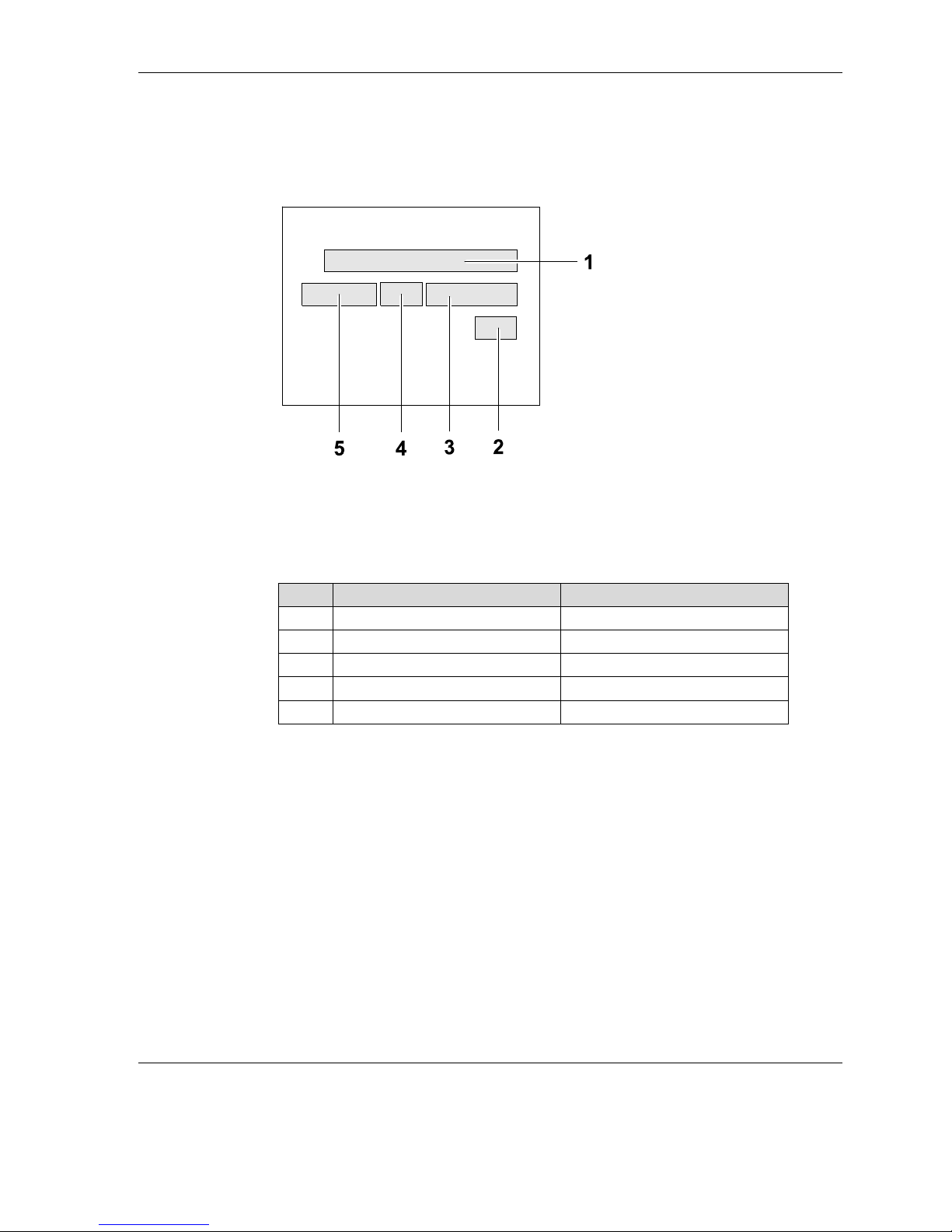
2.9 Identification of the machine
Nameplate data
The nameplate lists information that uniquely identifies this machine. This information is needed to order spare parts and when requesting additional technical
information.
Enter details on the machine in the following table:
Item Designation Your information
1 Group and type
2 Construction year
3 Machine no.
4 Version no.
5 Item no.
Page 12

3 Security
12
100_0202_si_0006.fm
3 Security
Notice: Read and observe all notes and safety instructions in this manual. Fail-
ure to comply with these instructions may lead to electric shock, fire
and/or serious injury and may cause damage to the machine and/or to
other objects. Store the safety instructions and notes for future use.
3.1 Policy
State of the art
The machine is built according to the latest state of the art and the recognized
safety rules. However, improper use can present hazards to the life and limb of
the user, third persons or damage the machine and other equipment during use.
Intended use
The machine may only be used for the following purposes:
Compacting soil.
Compacting asphalt.
Vibration of paving stones.
The machine may not be used for the following purposes:
Compacting of strongly cohesive soils.
Compacting frozen soil.
Compacting hard, non-compressible surfaces.
Compaction of unsound soils.
Intended use also includes the observance of all instructions and safety information in this manual, as well as complying with the required service and maintenance instructions.
Any other or additional use is considered improper. The manufacturer is not liable for any resulting damage. The risk is borne by the operator alone.
Page 13

3 Security
100_0202_si_0006.fm 13
Structural changes
Structural modifications may not be made without the written permission of the
manufacturer. Unauthorized structural changes of this machine may lead to hazards for users and/or third parties and damage to the machine.
The manufacturer is also not liable in the event of unauthorized structural changes.
In particular, the following cases are considered structural changes:
Opening the machine and the permanent removal of components.
Installation of spare parts that do not originate from Wacker Neuson or are
not comparable in the design system and quality of the original parts.
Fitting of any kind of accessories not originating from Wacker Neuson.
Spare parts or accessories from Wacker Neuson can be safely assembled or
mounted.
3.2 Responsibility of the operator
The operator is the person who operates this machine for industrial or commercial purposes or gives it to a third party for use / application and during operation
bears the legal product responsibility for the safety of personnel or third parties.
The operator must make the manual accessible to personnel at all times and ensure that the user has read and understood this manual.
The manual must be kept next to the machine or place of use.
The operator must hand over the manual to subsequent operators or owners of
the machine.
The country-specific regulations, standards, and guidelines on accident preven-
tion and environmental protection must be observed. The operator’s manual
must supplemented with additional instructions that take regulatory, national, or
generally applicable safety standards into consideration.
3.3 Obligations of the operator
To be familiar with and implement applicable health and safety regulations.
To identify in a risk assessment hazards arising from working conditions on
the site.
To create operator's manuals for the operation of this machine.
To periodically check whether the operation instructions reflect the current
state of the regulations.
To regulate and specify responsibilities for operation, troubleshooting, main-
tenance and cleaning.
To train personnel at regular intervals and inform them about possible dan-
gers.
To provide staff with the necessary protective equipment.
Page 14

3 Security
14
100_0202_si_0006.fm
3.4 Personnel qualifications
This machine may only be installed and operated by trained personnel.
Misapplication or misuse by untrained personnel can endanger the health of the
user and/or third parties, including damage to or total failure of the machine.
In addition, the following requirements apply to the user:
To be physically and mentally fit.
Not to be under the influence of drugs, alcohol or medication.
To be familiar with the safety instructions in this manual.
To be familiar with the proper use of this machine.
To be a minimum of 18 years of age to operate this machine.
Has been instructed in the independent operation of the machine.
Is entitled to operate equipment and systems independently, in accordance
with the standards of safety engineering.
3.5 General hazards
Residual hazards are special hazards that cannot be eliminated when dealing
with machines despite the safety-compliant construction.
These residual hazards are not obvious and can be a source of possible injury
or health hazards.
If unforeseen residual risks arise, the machine is to be switched off immediately
and the responsible manager informed. This manager will take further decisions
and will do everything necessary to eliminate the arising hazard.
If required, the machine manufacturer must be informed.
3.6 General safety information
The safety instructions in this chapter include the "General safety instructions",
which should be set out in the manual in accordance with the applicable standards. It may contain information not relevant for this machine.
Page 15

3 Security
100_0202_si_0006.fm 15
3.6.1 Working area
Before starting work be familiar with the working environment, e.g. the bear-
ing capacity of the soil or obstacles in the environment.
Make working area to public transport safe.
Secure the working area from the public transport area.
Keep working area tidy. Cluttered or poorly lit areas may lead to accidents.
Working with this machine in a potentially explosive environment is prohibit-
ed.
Keep children and other people away when operating this machine. Distrac-
tions may lead to loss of control of the machine.
Always secure the machine against tipping, rolling, sliding and crashing. Risk
of injury!
3.6.2 Service
Only allow the machine to be repaired or maintained by qualified technically
trained personnel.
Use only original spare parts and accessories. The operational safety of the
machine is thus maintained.
3.6.3 Personal safety
Working under the influence of drugs, alcohol or medication can lead to seri-
ous injury.
For all work appropriate protective equipment should be worn. Appropriate
personal protective equipment reduces the risk of injury considerably.
Remove tools before the machine is put into operation. Tools on a rotating
machine part can be ejected and cause serious injury.
Always ensure stability.
After prolonged working with this machine, vibration-induced long-term dam-
age cannot be ruled out completely. For exact values for vibration measurement, see chapter Technical data.
Wear appropriate clothing. Keep baggy or loose clothing, gloves, jewelry and
long hair away from moving/rotating machinery. Danger of being pulled in!
Ensure that no other individuals are in the danger zone!
Page 16

3 Security
16
100_0202_si_0006.fm
3.6.4 Handling and use
Handle machines with care. Do not operate machines with defective compo-
nents or operator’s controls. Immediately replace defective components or
operator’s controls. Machines with defective components or operator’s controls carry a high risk of injury!
The operator’s controls of the machine shall not be improperly locked, manip-
ulated, or changed.
Store unused machines out of the reach of children. Machines may only be
operated by authorized personnel.
Use the machine, accessories, tools etc. in accordance with these instruc-
tions.
After operation, store the cooled machine in a locked, clean, frost-protected
and dry location that is inaccessible to other people and children.
3.7 Specific safety instructions - vibratory plates
3.7.1 External influences
The vibratory plate must not be operated in the event of the following external
influences:
Heavy rain on inclined surfaces. Slipping hazard!
Oil field environments - methane leaks from the soil. Explosion hazard!
In dry, flammable vegetation. Fire hazard!
In potentially explosive environments. Explosion hazard!
Page 17

3 Security
100_0202_si_0006.fm 17
3.7.2 Operational safety
During operation of the machine ensure that no gas, water or ele ctric lines or
pipes are damaged.
The machine must not be used in tunnels or within closed areas in operation.
Pay the utmost attention near drops or slopes. Falling hazard!
The intended operator's position is behind the center pole, do not leave while
the unit is operational.
Do not allow the machine to run unattended. Risk of injury!
Demarcate work area spaciously and keep unauthorized persons away. Risk
of injury!
Operators this machine must ensure that persons who are present in the
work area comply with a minimum distance of 2 meters from the operational
machine.
Do not use start help sprays. They can cause misfires and engine damage.
Fire hazard!
When operating the machine on sloping surfaces, always approach gradients
from the bottom and always stand above the machine on a slope. The machine could slip or tip over.
Do not exceed the maximum permissible tilt of the machine - possible loss of
engine lubrication, see ChapterTechnical data.
Only Wacker Neuson use starter batteries. These are vibration proof and
therefore suitable for the high vibration exposure.
Page 18

3 Security
18
100_0202_si_0006.fm
3.7.3 Safety distances
Compaction work close to buildings can cause damage. For this reason, all potential impacts and vibrations have to be tested on surrounding buildings in advance.
The relevant rules and regulations for measuring, evaluating, and reducing vibration emissions — especially the DIN 4150-3 — must be considered.
Wacker Neuson accepts no liability for any damage to buildings.
3.8 General safety instructions - combustion engines
The following instructions must be adhered to:
Before starting work, check the engine to ensure there are no leaks and/or
cracks in the fuel lines, tank, and fuel cap.
Do not use a defective engine. Replace damaged parts immediately.
The preset engine speed must not be adjusted. This could lead to engine
damage.
Make sure that the exhaust system of the engine is free of debris. Fire haz-
ard!
Switch off before refueling the engine.
Use the correct fuel type. Fuel must not be mixed with other liquids.
For refueling, use clean filling aids. Do not spill fuel; wipe up any spilled fuel
immediately.
Engine must not be started near spilled fuel. Explosion hazard!
When operating in partially-enclosed spaces sufficient ventilation must be
provided. Do not breathe in exhaust fumes. Poisoning hazard!
The engine surface and exhaust system can quickly become extremely hot.
Risk of burns!
Notice: This machine is equipped with an EPA-certified engine.
Adjusting the speed influences the EPA certification and emissions.
Adjustments to this engine may only be carried out by a professional.
For more information, contact the engine manufacturer or the Wacker
Neuson contact partner.
Page 19

3 Security
100_0202_si_0006.fm 19
3.9 General safety instructions - fuel, lubricants or coolants
The following instructions must be adhered to:
Always wear safety glasses and protective gloves when handling fuel, lubri-
cants, and coolants. If hydraulic oil, fuel, oil, or coolant gets into your eyes,
see a doctor immediately.
Avoid direct skin contact with fuel, lubricants or coolants. Rinse skin immedi-
ately with soap and water.
Do not eat or drink while working with fuel, lubricants or coolants.
Hydraulic oil or fuel contaminated by dirt or water can cause premature wea r
or failure of the machine.
Dispose of discharged or spilled supplies according to applicable regulations
for environmental protection.
If fuel, lubricants or coolants emerge from the machine, cease operation of
the machine and immediately have it repaired by the Wacker Neuson contact
partner.
3.10 General safety instructions - Starter batteries
The following instructions must be adhered to:
When disconnecting the starter battery, always disconnect the negative ter-
minal first!
When connecting the starter battery, always connect the positive terminal
first! Fasten battery terminal cover!
Flames, sparks, and smoking are prohibited when handling starter batteries.
Starter batteries contain corrosive acid. Wear acid-proof protective gloves
and safety glasses when handling starter batteries.
Prevent incorrect connection of the starter battery or bridging of the terminals
with tools. Risk of short circuit!
Page 20

3 Security
20
100_0202_si_0006.fm
3.11 Maintenance
The following instructions must be adhered to:
This machine may not be maintained, repaired, adjusted or cleaned while
switched on.
Observe maintenance intervals.
After every maintenance or repair the safety devices on this machine must be
replaced.
Observe the maintenance schedule. Work not listed must be taken on by the
service of the Wacker Neuson contact partner.
Always immediately replace worn or damaged machine parts. Only use spare
parts from Wacker Neuson.
Keep the machine clean.
Missing, damaged or illegible safety stickers must be replaced immediately.
Safety stickers contain important information for the protection of the user.
Maintenance work must be carried out in a clean and dry environment (e.g.
a workshop).
Page 21

3 Security
100_0202_si_0006.fm 21
3.12 Personal Protection Equipment
Notice: To avoid personal injury as much as possible when using this machine,
personal protective equipment must be worn when working on or with
this machine.
Notice: With this machine, the permissible, country-specific noise limit (per-
sonal rating level) can be exceeded. Therefore, ear protection must be
worn. For exact values of noise emissions, refer to the Technical Data
section.
Work particularly cautiously and pay attention when wearing ear protection, as the ability to hear noises, such as screams or signal tones,
is restricted.
Wacker Neuson recommends always wearing ear protection.
Pictogram Significance Description
Use safety shoes! Safety shoes protect against
crushing, falling and slipping on
slippery surfaces.
Use protective gloves! Protective gloves protect
against abrasions, cuts, punctures as well as hot surfaces.
Use ear protection! Ear protection protects against
permanent hearing damage.
Page 22
3 Security
22
100_0202_si_0006.fm
3.13 Safety equipment
Safety equipment protects the user of this machine before exposing themselves
to existing hazards. These are barriers (protective devices) or other technical
measures. They prevent exposing users to danger. In certain situations the
threat source is turned off and the risk reduced.
This machine has the following safety equipment:
Notice: Loosened screw connections are to be tightened to the specified tight-
ening torque.
Pos. Description
1 Contact protection of ex ha u st system
2 Belt guard
3 Automatic neutral position control handle
Page 23

3 Security
100_0202_si_0006.fm 23
3.14 Behavior in dangerous situations
Preventive measures:
Always be prepared for accidents.
Have first-aid facilities at hand.
Make personnel familiar with accident, first aid and rescue facilities.
Keep access routes clear for emergency vehicles.
Train personnel in first aid measures.
g
Measures in case of emergency:
Switch off machine immediately.
Remove injured and other persons from the danger area.
Perform first aid measures.
Alert rescue workers.
Keep access routes clear for emergency vehicles.
Inform managers on site.
Page 24
4 Safety and information labels
24
100_0202_ls_0006.fm
4 Safety and information labels
The following stickers are found on the machine:
WARNING
Illegible symbols
Over time, stickers and signs on the machine can get dirty or otherwise become
illegible.
Keep all safety, warning, and operating instructions on the machine in good
readable condition.
Replace damaged stickers and signs immediately.
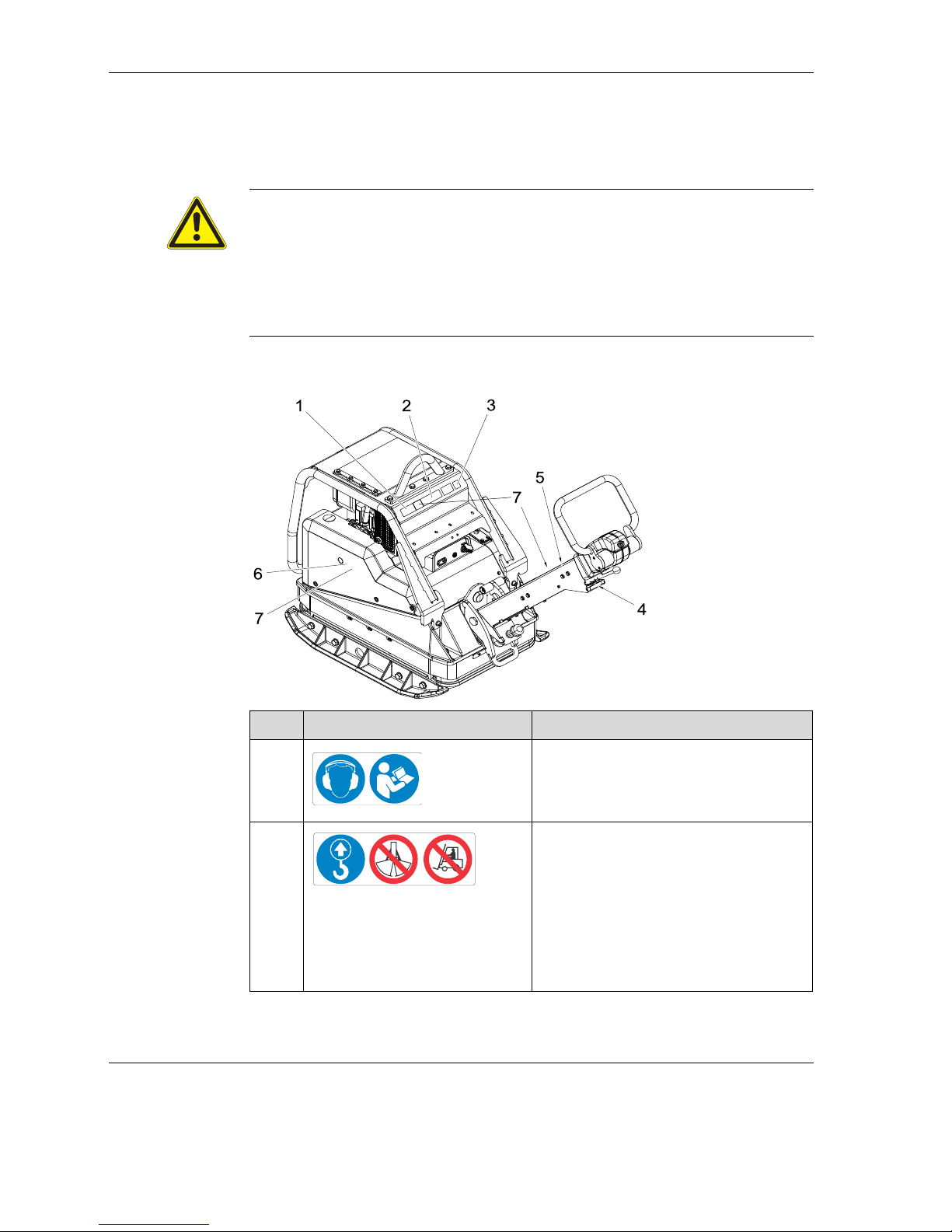
Pos. Label Description
1 Use personal protection equipment in or-
der to avoid injuries and health hazards:
Ear protection.
Read operator's manual.
2 A falling machine can cause serious inju-
ry.
Only lift the machine at the central lift-
ing point with certified hoist and lifting
tackle (safety load hook).
Do not lift the machine with excavator
bucket at the central lifting point.
Do not lift the machine with forklift at
the central lifting point.
0219175
0216633
Page 25
4 Safety and information labels
100_0202_ls_0006.fm 25
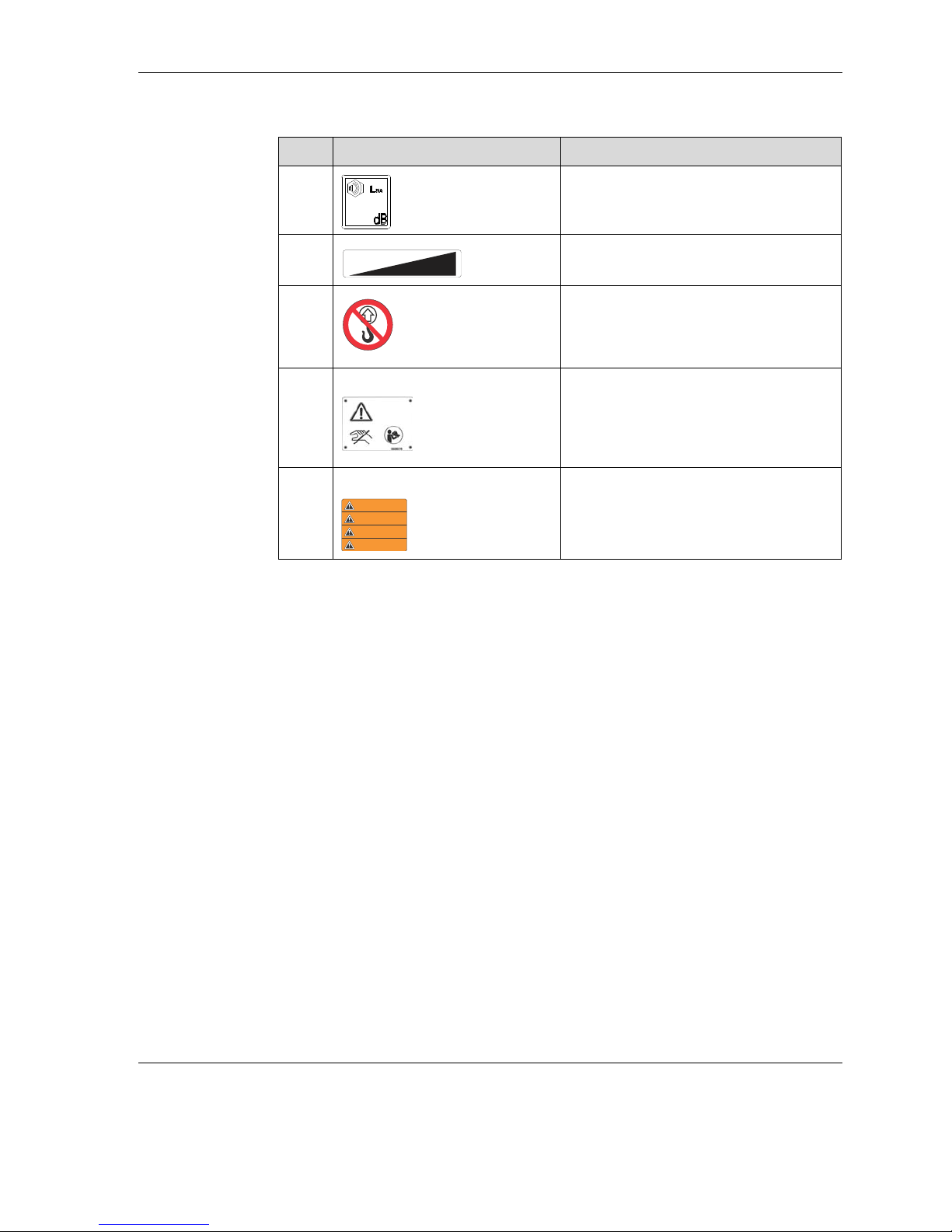
3 Guaranteed sound power level.
4 Start-stop.
5 A falling machine can cause serious inju-
ry.
Do not lift the machine at the control
handle or the centre pole.
6 DPU 45.., DPU 55.. Warning.
Body parts can be crushed or cut by rotating engine parts.
Do not touch once the starting crank is
active.
7
US machines
Warning.
Pos. Label Description
0219259
0
2
2
0
0
0
0
0219261
WARNING
WARNUNG
ADVERTENCIA
ADVERTISSEMENT
0219176
Page 26

5 Construction and function
26
100_0202_sf_0006.fm
5 Construction and function
5.1 Items supplied
The machine is delivered fully assembled and is ready for operation out of the
box.
Included in the delivery:
Vibratory plate
Starting crank (optional)
Operator’s manual
5.2 Application
The vibratory plate is used for the compaction of soils and is used in gardening
and landscaping, civil engineering and road and pavement construction.
5.3 Brief description
The vibratory plate is a machine that compacts soil.
The vibration required for compaction is produced by the exciter firmly connected
to the base plate. This exciter is designed as a central vibrator with aligned vib rations. Such a principle permits a change in the oscillation direction by turning the
eccentric weights.
Thus a continuous transition between compaction during advance travel, when
standing still and in reverse travel is possible. This process is controlled hydraulically with the control handle on the centre pole head.
The drive motor secured to the upper mass drives the exciter. The torque is firmly
transmitted via the centrifugal clutch and the exciter V-belt.
The centrifugal clutch interrupts at low engine speed the flow of power to the exciter and thus permits flawless idling of the drive motor.
The automatic V-belt pulley combined with the centrifugal clutch ensure s during
operation an optimum voltage of the exciter V-belt and relief of the exciter V-belt
when moving or when transporting the machine.
In addition, the automatic V-belt pulley automatically adjusts itself according to
the wear on the V-belt edges and thus makes the entire drive from the engine to
the exciter maintenance-free.
The speed of the drive motor can be varied continuously, operated remotely by
the throttle control lever and locked in the idle setting. Upper mass and base
plate are connected to each other by 4 vibration rubber mounts. This damping
prevents transmission of very high frequencies to the upper mass. Thus the functionality of the drive motor is maintained despite a high compaction performance.
Page 27

5 Construction and function
100_0202_sf_0006.fm 27
The drive motor operates according to the Diesel principle, is started electrically
through a gear and pinion starter, sucks combustion air through a dry air filter
and is air-cooled.
To facilitate the starting procedure (at very cold temperatures, with manual start)
the drive motor has a decompression system. It causes the compression during
cranking to be very low, but steadily increases after a few turns and then switches over to full compression.
Operating hour meter (optional)
On the operating hour meter, the operating hours of the machine can be accurately read, thereby allowing for better observance of the maintenance intervals.
Extension plates (optional)
For larger working areas, additional mounting plates are recommended.
Compatec - compaction display (optional)
The Compatec compaction display is attached to the battery cover and is within
the operator’s line-of-sight. The display, consisting of eight LEDs that adapt to
light conditions, shows the relative compaction progress during driving through
successive illumination. When the number of illuminated LED's stops increasing,
then no further compaction can be achieved with the unit in use. The operator
can finish his work and avoids unnecessary passes or an over compaction of the
soil.
An additional function is the overload display if the machine is operated on too
hard of a substrate. The operator is notified of this through rapid flashing of all
eight LED's.
The Compatec compaction display is suitable for all good and mixed (well graded) soils.
Notice: The Compatec compaction display only serves to assist in soil com-
paction and does not replace professional measurement of soil density
by a professional.
Page 28

5 Construction and function
28
100_0202_sf_0006.fm
Narrow protective frame (optional)
For narrow cable trenches, the narrow protective frame is recommended.
5.4 Versions
In this operator's manual different machine types are listed:
Versions Description
e Electric starter
h Operating hour meter
ap Extension plates
c Compatec compaction display
s Narrow protective frame
Page 29
6 Components and operator controls
100_0202_cp_0004.fm 29
6 Components and operator controls
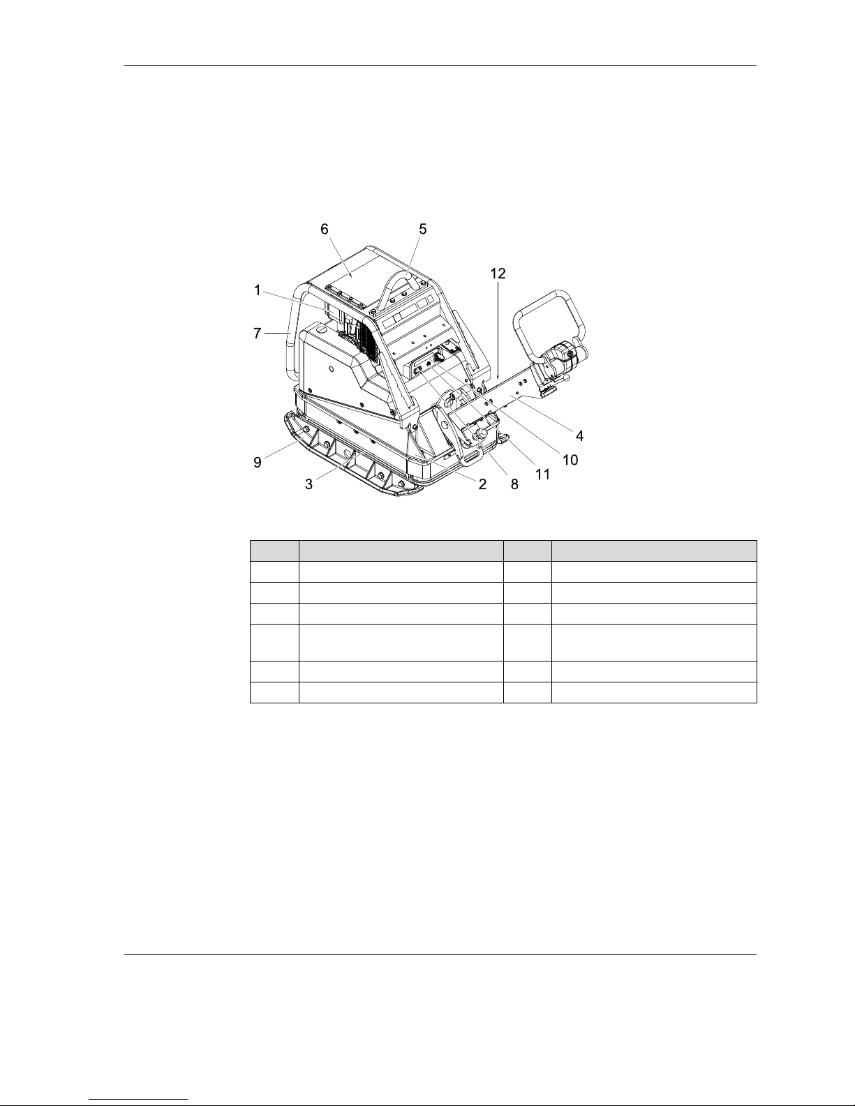
6.1 Components
Centre pole
The optimum working height of the centre pole can be changed by adjusting the
threaded spindle.
Central suspension
The central lifting point is used to lift the machine. It is located exactly at the centre of gravity of the machine, but can be set back for applications where the
height is crucial.
Pos. Designation Pos. Designation
1 Engine 7 Protective frame
2 Upper mass 8 Operating hour meter (optional)
3 Base plate 9 Extension plates (optional)
4 Centre pole 10 Compatec compaction display
(optional)
5 Central suspension 11 Control lamp operation
6 Fuel tank 12 Nameplate
Page 30
6 Components and operator controls
30
100_0202_cp_0004.fm
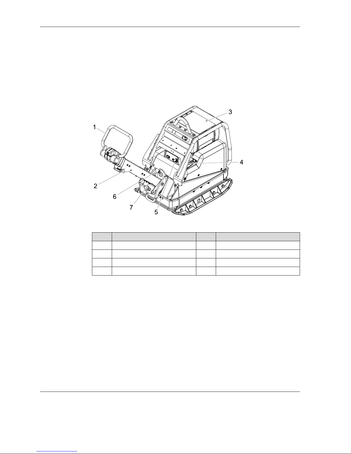
6.2 Operating elements
Always keep displays and operating elements of the machine clean, dry and free
of oil and grease.
Operator's controls such as the ON/OFF switch, throttle grips etc. may not be
locked, manipulated or changed without authorisation.
Control handle
The control handle is used for continuous regulation of the speed and direction
of travel.
Throttle control lever
The speed of the drive motor can be varied continuously, operated remotely by
the throttle control lever and locked in the idle setting.
Decompression lever
The decompression lever may only be operated to start the engine.
Jump-start
The jump-start facilitates connecting the jumper cable when jump-starting.
Pos. Designation Pos. Designation
1 Control handle 5 Ignition lock
2 Throttle control lever 6 Grip for centre pole lock
3 Decompression lever 7 Threaded spindle
4 Jump-start
Page 31

6 Components and operator controls
100_0202_cp_0004.fm 31
Grip for centre pole lock
The grip for centre pole lock is used to release the centre pole in order to bring it
into the working position.
Threaded spindle
The threaded spindle is used to set the optimum working height of the centre
pole.
Page 32

7 Transport
32
100_0202_tr_0006.fm
7 Transport
WARNING
Improper handling may result in injury or serious material damage.
Read and follow all safety instructions in this operator's manual.
DANGER
Danger of falling.
A falling machine can cause serious injury, e.g. by crushing.
Only use suitable and tested hoisting gear and lifting tackle (safety load
hooks) with sufficient capacity.
Only lift the machine at the central lifting point.
Safely secure the machine to the hoist.
Do not lift the machine with excavator bucket or forklift at the central lifting
point.
Do not lift the machine at the control handle.
Evacuate danger area when lifting, do not stand under suspended loads.
WARNING
Fire and explosion hazard due to fuel.
Spilled fuel can ignite and cause serious burns.
Lift and transport the machine upright.
CAUTION
If the central lifting point of the machine is mounted offset, the machine is no
longer in balance and can tip backwards.
Page 33

7 Transport
100_0202_tr_0006.fm 33
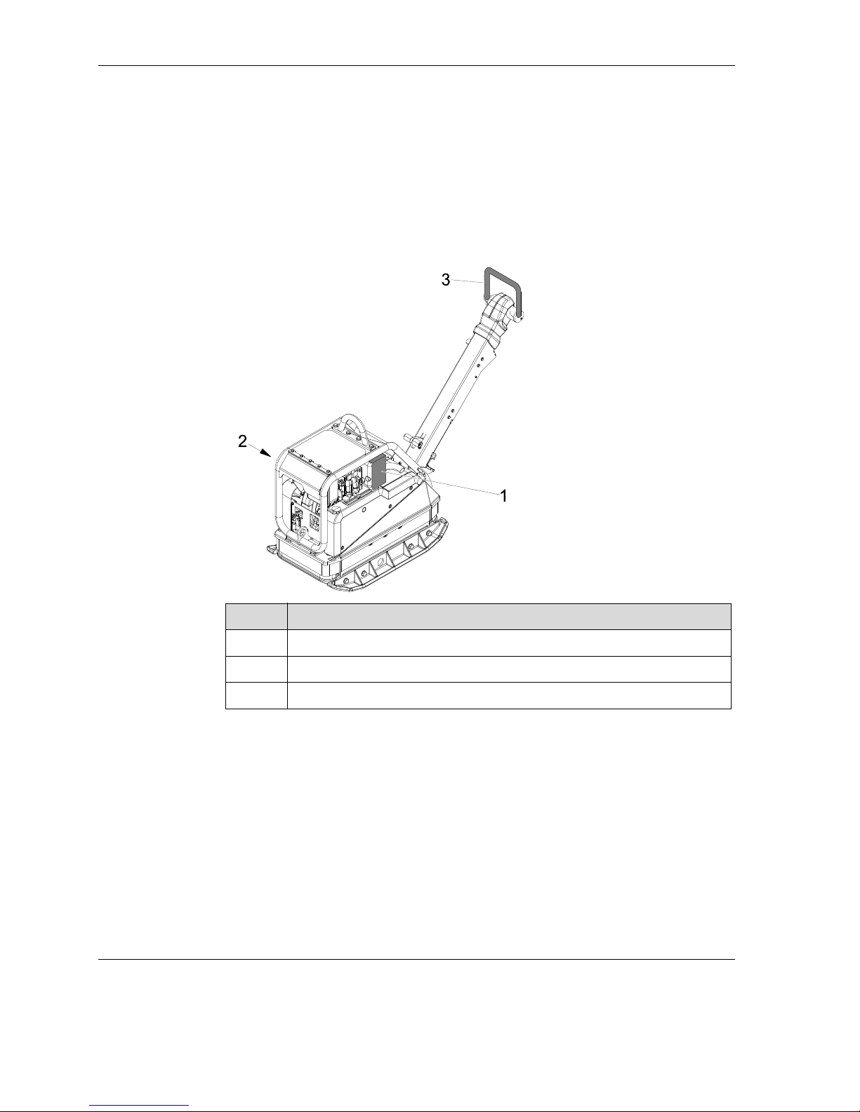
7.1 Loading and transport
Carry out preparations
Note: Wacker Neuson recommends emptying the fuel tank before transport.
During loading and transporting the centre pole must be locked by engaging the
grip for the centre pole lock in a vertical centre pole position.
Pos. Designation Pos. Designation
1 Centre pole 2 Grip for centre pole lock
2
1
Page 34

7 Transport
34
100_0202_tr_0006.fm
Lifting and tying down the machine
Note: Designate a flagman for safe lifting.
1. When lifting the machine, attach suitable lifting tackle to the central suspension.
2. Load machine carefully in or on a viable and safe means of transport.
3. After loading, tie down the machine so that it is secured against rolling, sliding
and tipping over. Tie down using the provided tie-down lugs.
Pos. Designation Pos. Designation
1 Central suspension 2 Securing eyelets
Pos. Designation
1Belt
2
2
1
Page 35

8 Use and operation
100_0202_op_0009.fm 35
8 Use and operation
8.1 Before starting
8.1.1 Checks before starting
Check engine and components for damage. If there is visible damage do not
operate the machine and contact a Wacker Neuson dealer immediately.
Ensure that loose packing material has been removed from the machine.
Check the fuel supply.
Check engine oil level.
Check hydraulic oil level.
Check fuel lines for tightness.
Make sure the screwed connections are firmly in place.
Note: Perform tests in accordance with the chapter Maintenance, top up fuel, lu-
bricants or coolants if necessary, see chapter Technical data.
WARNING
Improper handling may result in injury or serious material damage.
Read and follow all safety instructions in this operator's manual.
Page 36

8 Use and operation
36
100_0202_op_0009.fm
8.1.2 Adjust centre pole
The optimum working height of the centre pole can be set by adjusting the
threaded spindle.
8.2 Notes on operation
Pos. Designation Pos. Designation
1 Centre pole 2 Threaded spindle
WARNING
Danger of tipping
Risk of serious injury by machine slipping or tipping.
In the vicinity of edges is at least 2/3 of the machine must be on a sound
surface.
Turn the machine off and lift back onto a sound surface.
WARNING
Health hazard due to exhaust fumes
This engine's exhaust fumes contain chemicals which are known to the
State of California to be linked with cancer, birth defects or other reproductive problems.
2
1
Page 37

8 Use and operation
100_0202_op_0009.fm 37
Operating on inclined surfaces
Within a sloping area always stand above the machine.
Only approach gradients from the bottom (a gradient which can be easily
overcome upwards can be performed downwards without any risk).
Do not stand in the direction of descent of the machine.
Do not exceed the maximum permissible tilt, see chapter Technical data.
Only operate briefly in maximum permissible tilt.
Note: If the maximum permissible tilt is exceeded, this implicates a failure of the
engine lubrication and thus inevitably a defect in major engine parts.
Vibration of paving stones
In the event of compaction of interlocking paving stones, Wacker Neuson recommends the use of the slider to prevent damage to the machine and compaction
material, see the accessories chapter.
8.3 Starting
DANGER
Fire hazard
Start help sprays are highly flammable, they may ignite and cause severe
burns.
Do not use start help sprays.
Page 38

8 Use and operation
38
100_0202_op_0009.fm
8.3.1 Starting the machine (manual start)
1. Set the throttle control lever to full throttle position.
2. Pull decompression lever upwards.
Note: In this position, the decompression system engages and the engine is
ready to start.
3. Set sideways by the machine.
4. Insert the starting crank in the support.
WARNING
Starting crank can cause serious injury.
Do not use a defective starting crank.
Only use a clean starting crank.
Pos. Designation Pos. Designation
1 Throttle control lever 3 Starting crank support
2 Decompression lever
1
2
3
Page 39

8 Use and operation
100_0202_op_0009.fm 39
5. Grasp handle grip with one hand, with the other hand support the prote ctive
cage.
Note: After engagement of the automatic decompression five turns of the start-
ing crank are required until the engine can compress again and ignite.
6. Turn the handle slowly anticlockwise, until the jack engages. Then rotate
powerfully with increasing speed.
Note: Once the engine starts, the decompression lever unlatches (maximum
speed must be reached), the engine starts and the vibration begins.
The firm connection between the engine and the starting crank must be
guaranteed by holding the crank handle without twisting and fast turning
and must not be interrupted during the boot process under any circumstances.
If during the start-up process a setback occurs due to weak cranking, using the handle grip, the crank web / starting crank connection is disengaged with a short reverse rotation.
With repeated start-up attempts, wait for the engine to stop. Do not activate the decompression lever while the engine is running.
7. Pull out the starting crank from the support.
8. Set the throttle control lever to idle position, engage.
9. Hang the starting crank in the provided bracket.
10.Let the machine warm up for several minutes idle.
Page 40

8 Use and operation
40
100_0202_op_0009.fm
8.3.2 Cold starting the machine (manual start)
Note: The engine should rotate freely at temperatures below -5 °C.
1. Bring decompression lever to neutral position.
2. Crank the engine with the crank handle anticlockwise until it can rotate noticeably more freely (10 - 20 crank turns).
3. Press the hand lever of the mechanical oil pressure monitoring for 15 seconds.
Note: In the area of the cover of the metering device, remove dirt and take off
the lid.
4. In the metering device add engine oil up to the upper edge.
5. Replace cover and press it in firmly.
Note: Two fillings in succession are necessary.
6. Pull up decompression lever to the hilt.
7. Then start the engine immediately, see chapter Start ing the machine (manual
start).
Pos. Designation Pos. Designation
1 Decompression lever 3 Metering device
2 Hand lever oil pressure monitor-
ing
1
3
2
Page 41

8 Use and operation
100_0202_op_0009.fm 41
8.3.3 Starting the machine (electric starter)
1. Set the throttle control lever to full throttle position.
Note: In extreme cold also operate the decompression lever - set upwards. In
this position, the decompression system engages and the engine is ready
to start.
2. Insert the ignition key and turn to the right, the charging indicator light will
shine, the acoustic signal will sound.
3. Turn ignition switch key to position ll. As soon as the engine starts, release
the ignition switch key.
Note: Once the engine starts, the vibration begins.
4. Set the throttle control lever to idle.
5. Let the machine warm up for several minutes idle.
Pos. Designation Pos. Designation
1 Throttle control lever 3 Ignition lock
2 Decompression lever 4 Charging indicator light
Page 42
8 Use and operation
42
100_0202_op_0009.fm
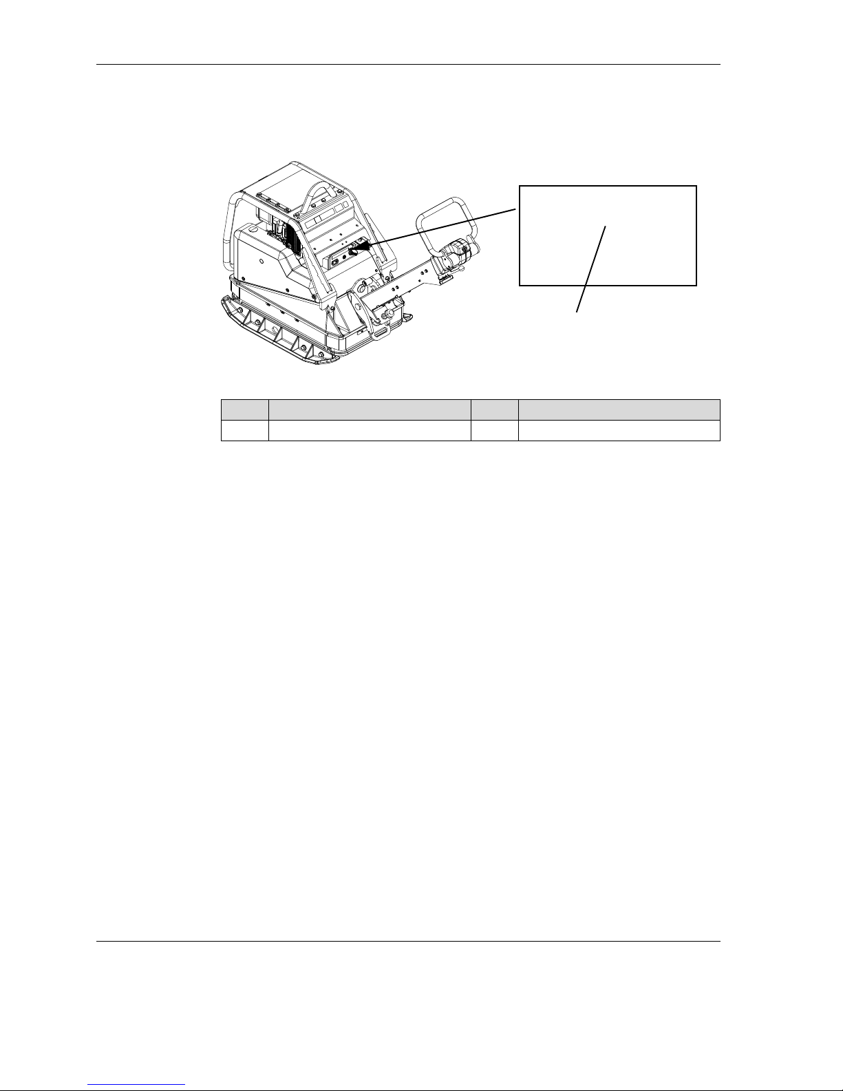
Machine with Compatec - compaction display (optional)
1. During the first few seconds after starting the engine a light bar indicator appears on the display unit.
2. The LEDs light up from left to right.
Note: If all LEDs light up, the system is fault-free and the LEDs will switch off in
succession.
3. All the LEDs will light up again briefly with reduced brightness.
4. Thus, the sensor has been successfully tested and the display unit is ready
for operation.
Note: If all LEDs light up permanently after initialisation, the sensor has not
been successfully tested, see chapter Troubleshooting.
Pos. Designation Pos. Designation
1 Display unit 2 LEDs / light bar indicator
1
2
Page 43

8 Use and operation
100_0202_op_0009.fm 43
8.4 Operation
The intended operator space is behind the machine.
Hold and steer the machine using the control handle.
8.4.1 Choose travel direction
1. Set the throttle control lever to full throttle position.
2. Select travel direction and speed with the control handle.
8.4.2 Compatec - Read compaction display
This display is a rough guide to the progress of work during compaction.
Note: To protect the machine, the display unit warns the operator in case of
over-compaction by rapid flashing of all LEDs. The brightness of the LEDs
adjusts automatically to the lighting conditions of the work area.
The number of LEDs lit is proportional to the density of soil, more lit LEDs
means more soil density.
Note: The discovery of flaws (non compactable material) is possible if the flaw
is longer than a meter.
With sudden changes from high to low compacted soil (or vice versa),
there is a slow rise or fall in the LEDs.
8.5 Turning off
Note: The machine does not take the decompression lever out of operation, as
this may lead to damage to the machine or engine.
Pos. Designation Pos. Designation
1 forwards 2 backwards
1
2
Page 44

8 Use and operation
44
100_0202_op_0009.fm
8.5.1 Turning off the machine (manual start)
1. Pull back gas throttle lever to the hilt.
2. Engine stops.
8.5.2 Turning off the machine (electric starter)
1. Pull back gas throttle lever to the hilt.
2. Once the engine has stopped, turn the ignition key to the left stop and pull
out, the charging indicator light goes out, the acoustic signal is silent.
Note: The Compatec compaction display automatically switches off as soon as
the ignition key is removed. The display unit does not have a sleep function. Continuous operation without engine operation leads to the battery
draining.
Pos. Designation
1 Throttle control lever
Pos. Designation Pos. Designation
1 Throttle control lever 3 Charging indicator light
2 Ignition lock
1
1
3
2
Page 45

9 Maintenance
100_0202_mt_0008.fm 45
9 Maintenance
WARNING
Improper handling may result in injury or serious material damage.
Read and follow all safety instructions in this manual.
WARNING
Danger of poisoning by exhaust fumes.
Exhaust fumes contain poisonous carbon monoxide, which may lead to unconsciousness or death.
Only perform maintenance work when the engine is switched off and the
machine is idle.
WARNING
Risk of injury from the machine starting in an uncontrolled manner and moving
parts.
Only perform maintenance work when the engine is switched off and the
machine is idle.
WARNING
Fire and explosion hazard due to fuel and fuel vapors
Fuel and fuel vapors can ignite or catch fire and cause serious burns.
No smoking.
Do not refuel near an open flame.
Before refueling, switch off engine and allow to cool.
WARNING
Hot surface warning
Exhaust muffler and engine can become very hot, which can cause severe
burns upon contact with the skin after a very short time.
Always allow machine to cool after use.
If the cooling period cannot be adhered to (e.g. due to an emergency), use
heat-resistant protective gloves.
Page 46

9 Maintenance
46
100_0202_mt_0008.fm
9.1 Maintenance table
WARNING
Risk of injury due to non-existent or non-functioning safety devices.
Only operate the machine if the safety devices are properly installed and
working.
Do not modify or remove safety devices.
Maintenance work daily h /Y weekly monthly
Clean machine
Inspection for completeness
Inspection for damage
Check engine oil level*
Change engine oil* 25 h /
250 h
Change engine oil filter* 25 h /
250 h
Clean, adjust, repair, change fuel injectors* 1500 h
Clean, adjust, repair, change injection valve* 3000 h
Change fuel filter* 500 h
Check water trap*
Check intake area of the combustion air*
Check air filter maintenance indicator*
Clean air filter cartridge* 500 h
Check tapped clearance** 25 h /
250 h
Check exciter oil level
Change exciter oil 250 h /
1/2 y
Check hydraulic oil level**
Check hydraulic hose lines** 125 h
Check - change V-belt
Check rubber buffer** 125 h
Page 47
9 Maintenance
100_0202_mt_0008.fm 47
9.2 Maintenance work
Carry out preparations
1. Place the machine on a level surface.
2. Turn the machine off.
3. Let the engine cool.
Make sure the screwed connections are firmly in
place.
Regrease threaded spindle and stop bolt pin
Check starter battery fluid level* 250 h
*Observe engine operator's manual
** This work is to be performed by the Wacker Neuson contact partner's service.
CAUTION
Health hazard due to fuel, lubricants and coolants.
Do not breathe in vapors, fuel, lubricants or coolants.
Avoid skin and eye contact with fuel, lubricants and coolants.
WARNING
Fire and explosion hazard due to fuel and fuel vapors.
No smoking.
Do not refuel near an open flame.
Before fuelling, switch off engine and allow to cool. Refuel only in well-venti-
lated areas.
Maintenance work daily h /Y weekly monthly
Page 48

9 Maintenance
48
100_0202_mt_0008.fm
Check fuel level and refill.
1. Fold cover on side.
2. Remove any dirt around the fuel filler neck.
3. Open fuel filler neck
4. Visually check fuel level
5. If necessary, refill fuel with a clean filling vessel
For fuel type see chapter Technical data.
Note: Fill fuel tank only to bottom of filler neck.
6. Close fuel cap securely.
Pos. Designation
1 Fuel filler neck
1
Page 49

9 Maintenance
100_0202_mt_0008.fm 49
Check water trap
1. Remove cover plate.
2. Loosen hexagonal bolt by 2-3 turns.
3. Collect the drops which emerge in a transparent container.
Note: Since water is heavier than diesel fuel, water appears first and then fuel.
This is indicated by a clear dividing line.
4. If only fuel emerges, tighten the hexagonal bolt.
5. Replace cover plate.
Clean machine
Note: Permeating water can damage the engine, electrical controls or compo-
nents of the machine. Do not direct high pressure washers directly at the
air intake area and electrical components.
1. After cleaning, check cables, hoses, lines and fittings for leaks, loose connections, abrasions and other damage.
2. Repair identified damage immediately.
Pos. Designation Pos. Designation
1 Cover plate 2 Hexagonal bolt
WARNING
Fire and explosion hazard when using flammable cleaning agents.
Do not clean the machine and components with gasoline or other solvents.
Page 50

9 Maintenance
50
100_0202_mt_0008.fm
Screwed connections
With vibration plates the screwed connections must be checked for tightness periodically.
Check and change V-belt and belt stabilizer
1. Remove V-belt guard
2. Check the condition of the V-belt and the belt stabilizer, if belt width is less
than the dimension of 15.5 mm or there is visible damage, it must be
changed.
3. Loosen screws.
4. Remove spindle, disc springs and seal.
5. Pull V-belt disc (engine) out from the machine, V-belt relaxes.
6. Press V-belt down until it drops from the V-belt disc.
7. Pull V-belt upwards.
Note: Do not oil or grease clutch components, destruction of graphite bushings
and slippage of the friction pads and V-belt.
8. Place a new V-belt on the V-belt disc (exciter) and press on the V-belt disc
(engine).
Note: By reciprocal movement of the V-belt, check whether it is properly seated
in both V-belt discs.
9. Press V-belt disc (engine) inside towards the machine.
10.Tighten seal, disc springs and spindle with screw. Tightening torque 49 Nm.
Pos. Designation Pos. Designation
1 Belt guard 2 Screw
Page 51

9 Maintenance
100_0202_mt_0008.fm 51
Note: By using the automatic centrifugal clutch a re-tightening of the V-belt is
not required.
11.Replace and tighten the V-belt guard. Tightening torque 25 Nm.
Change exciter oil and check oil level
Note: Change oil and check oil level in the event of hot exciter oil. Machine must
be idle and level.
Note: To protect against oil spills, equip work surface with an impermeable film.
1. Tilt and prop up machine to the side of the filler boring.
2. Place a suitable container under the filler boring.
3. Remove any dirt around the filler boring.
4. Unscrew screw plug from filler boring, completely drain the used oil.
Note: Collect leaking or overflowing oil and, together with the used oil, dispose
of in an environmentally friendly manner in accordance with regulations.
5. Tilt and prop up machine on the other side.
Note: Only fill the prescribed amount of oil.
DANGER
Danger of scalding
Caution when draining hot oil.
Pos. Designation Pos. Designation
1 Screw plug 2 Filler boring
1, 2
Page 52

9 Maintenance
52
100_0202_mt_0008.fm
6. Fill new oil (for exciter oil type and quantity see chapter Technical Data) in the
filler boring, use appropriate and clean filling vessel.
7. Place the machine horizontally on a level surface.
8. Screw in the screw plug with sealing ring in the filler boring. Tightening torque
100 Nm.
Check starter battery fluid level
1. Remove battery cover.
Note: Check for damage to the coiled helix cable.
2. Unscrew screw caps from all cells.
3. Check whether the fluid level is in all cells is above the mark.
4. When the fluid level falls below the mark, add distilled water.
5. Screw back screw caps on all cells.
WARNING
Risk of injury from corrosive acid.
Wear protective glasses and chemical resistant protective gloves.
Pos. Designation Pos. Designation
1 Battery cover 3 Fluid level marking
2 Sealing caps 4 Coiled helix cable
2
31
4
Page 53

9 Maintenance
100_0202_mt_0008.fm 53
Note: Before installing the battery cover, ensure that the positive terminal cover
is attached. Make sure that the degassing tube is free of kinks.
When attaching the battery cover, pay attention to the coiled helix cable.
6. Replace battery cover.
Changing the starter battery
Note: Only Wacker Neuson use starter batteries.
Only replace defective starter batteries with Wacker Neuson starter batteries. See Technical Data section.
Only the Wacker Neuson starter battery is vibration proof and therefore
suitable for the high vibration exposure.
1. Remove battery cover.
Note: First disconnect negative terminal, then positive terminal.
2. Disconnect starter battery and remove degassing tube.
3. Lift out defective starter battery and remove battery protectors.
4. Attach battery protectors to the new starter battery.
DANGER
Electric shock
Risk of injury by simultaneously touching the positive terminal and ground.
Always disconnect the negative terminal first.
Always connected the positive terminal first.
Pos. Designation Pos. Designation
1 Battery cover 2 Starter battery
1
2
Page 54

9 Maintenance
54
100_0202_mt_0008.fm
5. Place the new starter battery and insert degassing tube.
Note: First connect positive terminal, then the negative terminal.
6. Connect starter battery.
Note: Before installing the battery cover, ensure that the positive terminal cover
is attached. Make sure that the degassing tube is free of kinks.
When attaching the battery, pay attention to the coiled helix cable.
7. Replace battery cover.
Pos. Designation Pos. Designation
1 Positive terminal cover 2 Degassing hose
3 Coiled helix cable
3
1
2
Page 55

10 Troubleshooting
100_0202_ts_0008.fm 55
10 Troubleshooting
10.1 Fault table
DANGER
Danger to life through unauthorised troubleshooting.
If faults arise with this machine that are not described in this manual, contact
the manufacturer. Do not arbitrarily fix faults.
Fault Possible causes Remedial measure
Reverse travel speed too low. Insufficient hydraulic oil in the
centre pole head.
Fill with hydraulic oil.
Forward speed too low. Too much hydraulic oil in the
centre pole head.
Correct oil level accordingly.*
Air in the hydraulic control system.
Bleed.*
Not moving forward. Mechanical fault. Have the machine repaired.*
*This work is to be performed by the Wacker Neuson contact partner's service.
Loss of hydraulic oil. Leaks Have the machine r epaired.*
Engine will not start. Defective ignition lock. Have the machine repaired.*
Defective starter motor.
Discharge starter battery. Charge starter battery.
Low oil level. Add oil and actuate valve lever
on the oil filter housing once.
Charge indicator light does not
go out.
Alternator failure. Have the machine repaired.*
Switch cannot be silenced. Regulator failure.
Compaction display (optional):
If all LEDs are permanently
flashing after initialisation, the
sensor has not been successfully tested.
Switch-on procedure when engine is running.
Have the machine repaired.*
Sensor failure.
Page 56

10 Troubleshooting
56
100_0202_ts_0008.fm
10.2 Performing jump start with donor battery
If the starter battery of the machine is discharged and the engine does not start,
a jump-start with a donor battery is possible.
Note: Use only insulated jumper cables with a cable cross-section of at least 16
mm.
WARNING
Explosion hazard due to oxyhydrogen.
Risk of injury from splashing acid.
Wear safety glasses and chemical resistant protective gloves.
The donor battery and starter battery of the machine must have the same
voltage (12 V).
Avoid short-circuit due to reverse polarity (plus to plus, minus to minus).
Follow sequence when connecting the jumper cables.
Page 57

10 Troubleshooting
100_0202_ts_0008.fm 57
1. Pull out jump-start and connect clamping tongs of the red jumper cable to the
jump-start.
2. Connect the second clamping pliers of the red jumper cable to the positive
terminal of the donor battery.
3. Connect the clamping pliers of the black jumper cable to the negative terminal of the donor battery.
4. Connect the second clamping pliers of the black jumper cable to a ground
point of the machine e.g. on the engine block.
Help starting
5. Start engine.
If the engine does not switch on after 15 seconds, abort start attempt and
Wacker Neuson contact partner.
6. Let the engine run for several minutes.
Disconnect the jumper cables
7. Disconnect the clamping pliers of the black jumper cable from the ground
point of the machine.
8. Disconnect the clamping pliers of the red jumper cable from the donor battery.
9. Disconnect clamping tongs of the red booster cable from the jump-start and
press jump-start in.
10.Disconnect the clamping pliers of the red jumper cable from the positive terminal of the donor battery.
Pos. Designation Pos. Designation
1 Jump-start 4 Negative terminal of the donor
battery
2 Negative terminal at ground
point
5 Positive termin al of th e do no r
battery
3 Black jumper cable 6 Red jumper cable
Page 58

11 Disposal
58
100_0000_0007.fm
11 Disposal
11.1 Disposal of batteries
For customers in EU countries
This device contains one or more batteries or rechargeable batteries (hereafter
referred to as "batteries"). This battery is subject to the European Directive
2006/66/EC on (waste) batteries, as well as the corresponding national legislation. The battery directive outlines the procedure for handling batteries across
the EU.
The battery is labelled with the symbol of a crossed out dustbin
shown here. Below this symbol is a list of all the harmful substances
it contains, namely "Pb" for lead, "Cd" for cadmium and "Hg" for
mercury.
Batteries may not be disposed of with normal household waste. As
the end user, only dispose of waste batteries via the manufacturer, the dealer or
special collection points for this purpose (legal obligation to return), which is free
of charge. Dealers and manufacturers are obliged to accept the return of the batteries and to use them properly or to dispose of them as hazardous waste (legal
obligation to accept). You can also return any used batteries you obtained from
us free of charge. If you do not return the batteries to one of our branches personally, make sure you have paid sufficient postage for its return. Please also
note any information in the sales contract and the general terms and conditions
from the point of sales.
The proper disposal of the battery prevents the occurrence of any negative effects on people or the environment, follows the specific procedures for handling
harmful substances and enables valuable raw materials to be recycled.
For customers in non-EU countries
This device contains one or more batteries or rechargeable batteries (hereafter
referred to as "batteries"). The proper disposal of the battery prevents the occurrence of any negative effects on people or the environment, follows the specific
procedures for handling harmful substances and enables valuable raw materials
to be recycled. Therefore, we recommend that this battery is disposed of in a
separate, environmentally-friendly waste collection and not with normal household waste. In some cases, national legislation stipulates the separate disposal
of batteries. Please ensure you dispose of this battery in accordance with the valid regulations in your country.
Page 59

12 Accessories
100_0202_ac_0004.fm 59
12 Accessories
A wide range of accessories is available for the machine.
For more information on the individual accessories see
www.wackerneuson.com.
Extension plates
Extension plates are available for the machine in different widths, which can increase or reduce the width of the machine.
Sliding
Sliders provide maximum protection against damage to the paving stone surface, which is required especially in surface-coated paving locations.
Starting crank
DPU 4545 and DPU 5545 - short tool shank of the starting crank.
DPU 6555 - long tool shank of the starting crank.
Starting crank bracket
To hold the starting crank on the machine, a starting crank bracket can be mounted.
Chassis
A chassis is offered for easier transport to the construction site.
CAUTION
Accessories and spare parts not from Wacker Neuson may increase the risk of
injury and possible damage to the machine.
By using other accessories and spare parts not from Wacker Neuson all lia-
bility is eliminated.
Page 60

13 Technical data
60
100_0202_td_0015.fm
13 Technical data
Designation Unit DPU 4545H DPU 4545He DPU 4545Heh
Item no. 5100009661 5100016951 5100009659
Centrifugal force kN 45,00 45,00 45,00
Vibrations Hz 69 69 69
1/min 4.140 4.140 4.140
Surface capacity m
2
/h
(ft
2
/h)
910
(6.952))
910
(6.952))
910
(6.952))
Forward travel m/min
(ft/min)
25,0
(82.0)
25,0
(82.0)
25,0
(82.0)
Reverse travel m/min
(ft/min)
19,6
(62.3)
19,6
(62.3)
19,6
(62.3)
Gradeability % 57,7 57,7 57,7
Length (center pole in
working position)
mm (in) 1.661 (65.4) 1.661 (65.4) 1.661 (65.4)
Width mm (in) 604 (23.8) 604 (23.8) 604 (23.8)
Height mm (in) 1.308 (51.5) 1.308 (51.5) 1.308 (51.5)
Operating weight: kg (lb) 402,0 (886.3) 423,0 (932.5) 423,0 (932.5)
Ground clearance mm (in) 790 – 914
(31.1 - 36.0)
790 – 914
(31.1 - 36.0)
790 – 914
(31.1 - 36.0)
Rated performance** kW 6,4 6,4 6,4
nominal rotation speed 1/min 2.850 2.850 2.850
Exciter oil volume l 0,75 0,75 0,75
Exciter oil type SAE 10W40 SAE 10W40 SAE 10W40
Hydraulic oil volume l 0,5 0,5 0,5
Hydraulic oil type MR 520 MR 520 MR 520
Bearing temperature
range
°C
°F
-15 – +40
(-5 – +104)
-15 – +40
(-5 – +104)
-15 – +40
(-5 – +104)
Operating temperature
range
°C
°F
-15 – +40
(-5 – +104)
-15 – +40
(-5 – +104)
-15 – +40
(-5 – +104)
Sound pressure level
in operator space L
pA
dB(A) 94,0 94,0 94,0
Page 61

13 Technical data
100_0202_td_0015.fm 61
Standard EN 500-4
Sound power level L
wa
measured
guaranteed
dB(A)
106,1
108
106,1
108
106,1
108
Standard EN 500-4, 2000/14/EG
Vibration total value a
hv
Standard m/s
2
(ft/s2)
1,5
(4.9)
1,5
(4.9)
1,5
(4.9)
EN 500-4
Uncertainty of measurement of the vibration total
value a
hv
m/s
2
(ft/s2)
0,5
1.6)
0,5
1.6)
0,5
1.6)
* Depending on soil conditions.
** Accordance with the installed useful power according to Directive 2000/14/EC.
Designation Unit DPU 4545H DPU 4545He DPU 4545Heh
Page 62

13 Technical data
62
100_0202_td_0015.fm
Designation Unit DPU
4545Hec
DPU
4545Hech
DPU
4545Heh US
DPU
4545Hech US
Item no. 5100016953 5100015429 5100009660 5100016952
Centrifugal force kN 45,00 45,00 45,00 45,00
Vibrations Hz 69 69 69 69
1/min 4.140 4.140 4.140 4.140
Surface capacity m
2
/h
(ft
2
/h)
910
(6.952))
910
(6.952))
910
(6.952))
910
(6.952))
Forward travel m/min
(ft/min)
25,0
(82.0)
25,0
(82.0)
25,0
(82.0)
25,0
(82.0)
Reverse travel m/min
(ft/min)
19,6
(62.3)
19,6
(62.3)
19,6
(62.3)
19,6
(62.3)
Gradeability % 57,7 57,7 57,7 57,7
Length (center pole in
working position)
mm (in) 1.661 (65.4) 1.661 (65.4) 1.661 (65.4) 1.661 (65.4)
Width mm (in) 604 (23.8) 604 (23.8) 604 (23.8) 604 (23.8)
Height mm (in) 1.308 (51. 5) 1.308 (51.5) 1.308 (51.5) 1.308 (51.5)
Operating weight: kg (lb) 424,0
(934.8)
425,0
(937.0)
423,0
(932.5)
423,0 (932.5)
Ground clearance mm (in) 790 – 914
(31.1 - 36.0)
790 – 914
(31.1 - 36.0)
790 – 914
(31.1 - 36.0)
790 – 914
(31.1 - 36.0)
Rated performance** kW 6,4 6,4 6,4 6,4
nominal rotation speed 1/min 2.850 2.850 2.850 2.850
Exciter oil volume l 0,75 0,75 0,75 0,75
Exciter oil type SAE 10W40 SAE 10W40 SAE 10W40 SAE 10W40
Hydraulic oil volume l 0,5 0,5 0,5 0,5
Hydraulic oil type MR 520 MR 520 MR 520 MR 520
Bearing temperature
range
°C
°F
-15 – +40
(-5 – +104)
-15 – +40
(-5 – +104)
-15 – +40
(-5 – +104)
-15 – +40
(-5 – +104)
Operating temperature
range
°C
°F
-15 – +40
(-5 – +104)
-15 – +40
(-5 – +104)
-15 – +40
(-5 – +104)
-15 – +40
(-5 – +104)
Sound pressure level
in operator space L
pA
dB(A) 94,0 94,0 94,0 94,0
Standard EN 500-4
Page 63

13 Technical data
100_0202_td_0015.fm 63
Sound power level L
wa
measured
guaranteed
dB(A)
106,1
108
106,1
108
106,1
108
106,1
108
Standard EN 500-4, 2000/14/EG
Vibration total value a
hv
Standard m/s
2
(ft/s2)
1,5
(4.9)
1,5
(4.9)
1,5
(4.9)
1,5
(4.9)
EN 500-4
Uncertainty of measurement of the vibration total
value a
hv
m/s
2
(ft/s2)
0,5
1.6)
0,5
1.6)
0,5
1.6)
0,5
1.6)
* Depending on soil conditions.
** Accordance with the installed useful power according to Directive 2000/14/EC.
Designation Unit DPU
4545Hec
DPU
4545Hech
DPU
4545Heh US
DPU
4545Hech US
Page 64

13 Technical data
64
100_0202_td_0015.fm
13.1 Combustion engine
Designation Unit
Manufacturer Hatz
Engine type 1D42S-151 1D42S-152 1D42S-177
Combustion process four-cycle four-cycle four-cycle
Cooling Air cooling Air cooling Air cooling
Cylinders 1 1 1
Displacement cm³ (in³) 445 (27.2) 445 (27.2) 445 (27.2)
Max. permissible lift ° 30 30 30
Fuel type Diesel Diesel Diesel
Fuel consumption l/h
(gal/h)
1,6
(0.4)
1,6
(0.4)
1,6
(0.4)
Tank capacity l (gal 5,0 (1.3) 5,0 (1.3) 5,0 (1.3)
Oil specification SAE 10W40 SAE 10W40 SAE 10W40
Max. oil fill l (gal) 1,1 (0.3) 1,1 (0.3) 1,1 (0.3)
Max. power kW 7,0 7,0 7,0
Standard DIN ISO 3046 IFN
Speed (max. power) 1/min 3.600 3.600 3.600
Rated performance kW 6,4 6,4 5 ,8
Standard DIN ISO 3046 IFN
nominal rotation speed 1/min 2.850 2.850 2.850
Rated power output kW 4,9 4,9 4,9
Standard DIN ISO 3046 IFN
Operating speed
Standard
1/min 3.000 3.000 3.000
DIN ISO 3046 IFN
Upper engine speed without load
1/min 3.060 3.060 3.060
Air cleaner Dry air filter Dry air filter Dry air filter
Starter type Crank handle
start
Electric starter Electric starter
Page 65

13 Technical data
100_0202_td_0015.fm 65
Battery voltage V – Spezial Wacker Neuson battery for
vibratory plates, 12 V, 46 Ah
Battery capacity (nominal
value)
Ah –
Designation Unit
Page 66

14 Technical data
66
100_0202_td_0016.fm
14 Technical data
Designation Unit DP U
5545H
DPU
5545He
DPU
5545Heh
DPU
5545Heap
Item no. 5100009656 5100016947 5100009652 5100016949
Centrifugal force kN 55,00 55,00 55,00 55,00
Vibrations Hz 69 69 69 69
1/min 4.150 4.150 4.150 4.150
Surface capacity m
2
/h
(ft
2
/h)
980
(7.486))
980
(7.486))
980
(7.486))
1,170
(8.938))
Forward travel m/min
(ft/min)
27,0
(88.6)
27,0
(88.6)
27,0
(88.6)
26,0
(85.3)
Reverse travel m/min
(ft/min)
20,0
(65.6)
20,0
(65.6)
20,0
(65.6)
20,0
(65.6)
Gradeability % 57,7 57,7 57,7 57,7
Length (center pole in
working position)
mm (in) 1.661 (65.4) 1.661 (65.4) 1.661 (65.4) 1.661 (65.4)
Width mm (in) 604 (23.8) 604 (23.8) 604 (23.8) 750 (29.5)
Height mm (in) 1.308 (51.5) 1.308 (51.5) 1.308 (51.5) 1.308 (51.5)
Operating weight: kg (lb) 399,0 (879.6) 424,0 (934.7) 424,0 (934.7) 447,0 (985.5)
Ground clearance mm (in) 790 – 914
(31.1 - 36.0)
790 – 914
(31.1 - 36.0)
790 – 914
(31.1 - 36.0)
790 – 914
(31.1 - 36.0)
Rated performance** kW 6,4 6,4 6,4 6,4
nominal rotation speed 1/min 2.850 2.850 2.850 2.850
Exciter oil volume l 0,75 0,75 0,75 0,75
Exciter oil type SAE 10W40 SAE 10W40 SAE 10W40 SAE 10W40
Hydraulic oil volume l 0,5 0,5 0,5 0,5
Hydraulic oil type MR 520 MR 520 MR 520 MR 520
Bearing temperature
range
°C
°F
-15 – +40
(-5 – +104)
-15 – +40
(-5 – +104)
-15 – +40
(-5 – +104)
-15 – +40
(-5 – +104)
Operating temperature
range
°C
°F
-15 – +40
(-5 – +104)
-15 – +40
(-5 – +104)
-15 – +40
(-5 – +104)
-15 – +40
(-5 – +104)
Sound pressure level
in operator space L
pA
dB(A) 94,0 94,0 94,0 94,0
Page 67

14 Technical data
100_0202_td_0016.fm 67
Standard EN 500-4
Sound power level L
wa
measured
guaranteed
dB(A)
107,1
108
107,1
108
107,1
108
107,1
108
Standard EN 500-4, 2000/14/EG
Vibration total value a
hv
Standard m/s
2
(ft/s2)
1,5
(4.9)
1,5
(4.9)
1,5
(4.9)
1,5
(4.9)
EN 500-4
Uncertainty of measurement of the vibration total
value a
hv
m/s
2
(ft/s2)
0,5
1.6)
0,5
1.6)
0,5
1.6)
0,5
1.6)
* Depending on soil conditions.
** Accordance with the installed useful power according to Directive 2000/14/EC.
Designation Unit DPU
5545H
DPU
5545He
DPU
5545Heh
DPU
5545Heap
Page 68

14 Technical data
68
100_0202_td_0016.fm
Designation Unit DPU 5545
Hehap
DPU 5545
Hec
DPU 5545
Hech
Item no. 5100009654 5100016950 5100009655
Centrifugal force kN 55,00 55,00 55,00
Vibrations Hz 69 69 69
1/min 4.150 4.150 4.150
Surface capacity m
2
/h
(ft
2
/h)
1.170
(8.938))
980
(7.486))
980
(7.486))
Forward travel m/min
(ft/min)
26,0
(85.3)
27,0
(88.6)
27,0
(88.6)
Reverse travel m/min
(ft/min)
20,0
(65.6)
20,0
(65.6)
20,0
(65.6)
Gradeability % 57,7 57,7 57,7
Length (center pole in
working position)
mm (in) 1.661 (65.4) 1.661 (65.4) 1.661 (65.4)
Width mm (in) 750 (29.5) 604 (23.8) 604 (23.8)
Height mm (in) 1.308 (51.5) 1.308 (51.5) 1.308 (51.5)
Operating weight: kg (lb) 44 7,0 (985.5) 425,0 (937.0) 425,0 (937.0)
Ground clearance mm (in) 790 – 914
(31.1 - 36.0)
790 – 914
(31.1 - 36.0)
790 – 914
(31.1 - 36.0)
Rated performance** kW 6,4 6,4 6,4
nominal rotation speed 1/min 2.850 2.850 2.850
Exciter oil volume l 0,75 0,75 0,75
Exciter oil type SAE 10W40 SAE 10W40 SAE 10W40
Hydraulic oil volume l 0,5 0,5 0,5
Hydraulic oil type MR 520 MR 520 MR 520
Bearing temperature
range
°C
°F
-15 – +40
(-5 – +104)
-15 – +40
(-5 – +104)
-15 – +40
(-5 – +104)
Operating temperature
range
°C
°F
-15 – +40
(-5 – +104)
-15 – +40
(-5 – +104)
-15 – +40
(-5 – +104)
Sound pressure level
in operator space L
pA
dB(A) 94,0 94,0 94,0
Page 69

14 Technical data
100_0202_td_0016.fm 69
Standard EN 500-4
Sound power level L
wa
measured
guaranteed
dB(A)
107,1
108
107,1
108
107,1
108
Standard EN 500-4, 2000/14/EG
Vibration total value a
hv
Standard m/s
2
(ft/s2)
1,5
(4.9)
1,5
(4.9)
1,5
(4.9)
EN 500-4
Uncertainty of measurement of the vibration total
value a
hv
m/s
2
(ft/s2)
0,5
1.6)
0,5
1.6)
0,5
1.6)
* Depending on soil conditions.
** Accordance with the installed useful power according to Directive 2000/14/EC.
Designation Unit DPU 5545
Hehap
DPU 5545
Hec
DPU 5545
Hech
Page 70

14 Technical data
70
100_0202_td_0016.fm
Designation Unit DPU 5545Hech US DPU 5545Heh US
Item no. 5100016948 5100009653
Centrifugal force kN 55,00 55,00
Vibrations Hz 69 69
1/min 4.150 4.150
Surface capacity m
2
/h
(ft
2
/h)
980
(7.486))
980
(7.486))
Forward travel m/min
(ft/min)
27,0
(88.6)
27,0
(88.6)
Reverse travel m/min
(ft/min)
20,0
(65.6)
20,0
(65.6)
Gradeability % 57,7 57,7
Length (center pole in
working position)
mm (in) 1.661 (65.4) 1.661 (6 5.4)
Width mm (in) 604 (23.8) 604 (23.8)
Height mm (in) 1.308 (51.5) 1.308 (51.5)
Operating weight: kg (lb) 424,0 (934.7) 424,0 (934.7)
Ground clearance mm (in) 790 – 914
(31.1 - 36.0)
790 – 914
(31.1 - 36.0)
Rated performance** kW 6,4 6,4
nominal rotation speed 1/min 2.850 2.850
Exciter oil volume l 0,75 0,75
Exciter oil type SAE 10W40 SAE 10W40
Hydraulic oil volume l 0,5 0,5
Hydraulic oil type MR 520 MR 520
Bearing temperature
range
°C
°F
-15 – +40
(-5 – +104)
-15 – +40
(-5 – +104)
Operating temperature
range
°C
°F
-15 – +40
(-5 – +104)
-15 – +40
(-5 – +104)
Sound pressure level
in operator space L
pA
dB(A) 94,0 94,0
Standard EN 500-4
Page 71

14 Technical data
100_0202_td_0016.fm 71
Sound power level L
wa
measured
guaranteed
dB(A)
107,1
108
107,1
108
Standard EN 500-4, 2000/14/EG
Vibration total value a
hv
Standard m/s
2
(ft/s2)
1,5
(4.9)
1,5
(4.9)
EN 500-4
Uncertainty of measurement of the vibration total
value a
hv
m/s
2
(ft/s2)
0,5
1.6)
0,5
1.6)
* Depending on soil conditions.
** Accordance with the installed useful power according to Directive 2000/14/EC.
Designation Unit DPU 5545Hech US DPU 5545Heh US
Page 72

14 Technical data
72
100_0202_td_0016.fm
14.1 Combustion engine
Designation Unit
Manufacturer Hatz
Engine type 1D42S-151 1D42S-152 1D42S-177
Combustion process four-cycle four-cycle four-cycle
Cooling Air cooling Air cooling Air cooling
Cylinders 1 1 1
Displacement cm³ (in³) 445 (27.2) 445 (27.2) 445 (27.2)
Max. permissible lift ° 30 30 30
Fuel type Diesel Diesel Diesel
Fuel consumption l/h
(gal/h)
1,6
(0.4)
1,6
(0.4)
1,6
(0.4)
Tank capacity l (gal 5,0 (1.3) 5,0 (1.3) 5,0 (1.3)
Oil specification SAE 10W40 SAE 10W40 SAE 10W40
Max. oil fill l (gal) 1,1 (0.3) 1,1 (0.3) 1,1 (0.3)
Max. power kW 7,0 7,0 7,0
Standard DIN ISO 3046 IFN
Speed (max. power) 1/min 3.600 3.600 3.600
Rated performance kW 6,4 6,4 5 ,8
Standard DIN ISO 3046 IFN
nominal rotation speed 1/min 2.850 2.850 2.850
Rated power output kW 4,9 4,9 4,9
Standard DIN ISO 3046 IFN
Operating speed
Standard
1/min 3.000 3.000 3.000
DIN ISO 3046 IFN
Upper engine speed without load
1/min 3.060 3.060 3.060
Air cleaner Dry air filter Dry air filter Dry air filter
Starter type Crank handle
start
Electric starter Electric starter
Page 73

14 Technical data
100_0202_td_0016.fm 73
Battery voltage V – Spezial Wacker Neuson battery for
vibratory plates, 12 V, 46 Ah
Battery capacity (nominal
value)
Ah –
Designation Unit
Page 74

15 Technical data
74
100_0202_td_0017.fm
15 Technical data
Designation Unit DPU 6555
H
DPU 6555
Hs
DPU 6555
He
DPU 6555
Heap
Item no. 5100009651 5100015773 5100016940 5100016943
Centrifugal force kN 65,00 65,00 65,00 65,00
Vibrations Hz 69 69 69 69
1/min 4.150 4.150 4.150 4.150
Surface capacity m
2
/h
(ft
2
/h)
1.200
(9.167))
1.200
(9.167))
1.200
(9.167))
1.450
(11.077)
Forward travel m/min
(ft/min)
28,0
(91.7)
28,0
(91.7)
28,0
(91.7)
28,0
(91.7)
Reverse travel m/min
(ft/min)
20,5
(65.6)
20,5
(65.6)
20,5
(65.6)
20,5
(65.6)
Gradeability % 46,6 46,6 46,6 46,6
Length (center pole in
working position)
mm (in) 1.664 (78.5) 1.664 (78.5) 1.664 (78.5) 1.664 (78.5)
Width mm (in) 710 (27.9) 710 (27.9) 710 (27.9) 860 (33.8)
Height mm (in) 1.308 (51.5) 1.308 (51.5) 1.308 (51.5) 1.308 (51.5)
Operating weight: kg (lb) 480,0 (1058) 482,0 (1063) 504,0 (1111) 527,0 (1162)
Ground clearance mm (in) 861 – 1.005
(33.9 - 39.6)
861 – 1.005
(33.9 - 39.6)
861 – 1.005
(33.9 - 39.6)
861 – 1.005
(33.9 - 39.6)
Rated performance** kW 9,6 9,6 9,6 9,6
nominal rotation speed 1/min 2.800 2.800 2.800 2.800
Exciter oil volume l 0,75 0,75 0,75 0,75
Exciter oil type SAE 10W40 SAE 10W40 SAE 10W40 SAE 10W40
Hydraulic oil volume l 0,5 0,5 0,5 0,5
Hydraulic oil type MR 520 MR 520 MR 520 MR 520
Bearing temperature
range
°C
°F
-15 – +40
(-5 – +104)
-15 – +40
(-5 – +104)
-15 – +40
(-5 – +104)
-15 – +40
(-5 – +104)
Operating temperature
range
°C
°F
-15 – +40
(-5 – +104)
-15 – +40
(-5 – +104)
-15 – +40
(-5 – +104)
-15 – +40
(-5 – +104)
Sound pressure level
in operator space L
pA
dB(A) 97,0 97,0 97,0 97,0
Page 75

15 Technical data
100_0202_td_0017.fm 75
Standard EN 500-4
Sound power level L
wa
measured
guaranteed
dB(A)
108
109
108
109
108
109
108
109
Standard EN 500-4, 2000/14/EG
Vibration total value a
hv
Standard m/s
2
(ft/s2)
1,3
(4.9)
1,5
(4.9)
1,5
(4.9)
1,5
(4.9)
EN 500-4
Uncertainty of measurement of the vibration total
value a
hv
m/s
2
(ft/s2)
0,5
1.6)
0,5
1.6)
0,5
1.6)
0,5
1.6)
* Depending on soil conditions.
** Accordance with the installed useful power according to Directive 2000/14/EC.
Designation Unit DPU 6555
H
DPU 6555
Hs
DPU 6555
He
DPU 6555
Heap
Page 76

15 Technical data
76
100_0202_td_0017.fm
Designation Unit DP U
6555Heh
DPU 6555
Hehap
DPU 6555
Hes
DPU 6555
Hesh
Item no. 5100009636 5100009638 5100016941 5100015774
Centrifugal force kN 65,00 65,00 65,00 65,00
Vibrations Hz 69 69 69 69
1/min 4.150 4.150 4.150 4.150
Surface capacity m
2
/h
(ft
2
/h)
1.200
(9.167))
1.450
(11.077))
1.200
(9.167))
1.200
(9.167))
Forward travel m/min
(ft/min)
28,0
(91.7)
28,0
(91.7)
28,0
(91.7)
28,0
(91.7)
Reverse travel m/min
(ft/min)
20,5
(65.6)
20,5
(65.6)
20,5
(65.6)
20,5
(65.6)
Gradeability % 46,6 46,6 46,6 46,6
Length (center pole in
working position)
mm (in) 1.664 (78.5) 1.664 (78.5) 1.664 (78.5) 1.664 (78.5)
Width mm (in) 710 (27.9) 860 (33.9) 710 (27.9) 710 (27.9)
Height mm (in) 1.308 (51.5) 1.308 (51.5) 1.308 (51.5) 1.308 (51.5)
Operating weight: kg (lb) 495,0 (1091) 518,0 (1142) 499,0 (1100) 499,0 (1100)
Ground clearance mm (in) 861 – 1.005
(33.9 - 39.6)
861 – 1.005
(33.9 - 39.6)
861 – 1.005
(33.9 - 39.6)
861 – 1.005
(33.9 - 39.6)
Rated performance** kW 9,6 9,6 9,6 9,6
nominal rotation speed 1/min 2.800 2.800 2.800 2.800
Exciter oil volume l 0,75 0,75 0,75 0,75
Exciter oil type SAE 10W40 SAE 10W40 SAE 10W40 SAE 10W40
Hydraulic oil volume l 0,5 0,5 0,5 0,5
Hydraulic oil type MR 520 MR 520 MR 520 MR 520
Bearing temperature
range
°C
°F
-15 – +40
(-5 – +104)
-15 – +40
(-5 – +104)
-15 – +40
(-5 – +104)
-15 – +40
(-5 – +104)
Operating temperature
range
°C
°F
-15 – +40
(-5 – +104)
-15 – +40
(-5 – +104)
-15 – +40
(-5 – +104)
-15 – +40
(-5 – +104)
Sound pressure level
in operator space L
pA
dB(A) 97,0 97,0 97,0 97,0
Page 77

15 Technical data
100_0202_td_0017.fm 77
Standard EN 500-4
Sound power level L
wa
measured
guaranteed
dB(A)
108
109
108
109
108
109
108
109
Standard EN 500-4, 2000/14/EG
Vibration total value a
hv
Standard m/s
2
(ft/s2)
1,3
(4.3)
1,3
(4.3)
1,3
(4.3)
1,3
(4.3)
EN 500-4
Uncertainty of measurement of the vibration total
value a
hv
m/s
2
(ft/s2)
0,5
(1.6)
0,5
(1.6)
0,5
(1.6)
0,5
(1.6)
* Depending on soil conditions.
** Accordance with the installed useful power according to Directive 2000/14/EC.
Designation Unit DPU
6555Heh
DPU 6555
Hehap
DPU 6555
Hes
DPU 6555
Hesh
Page 78

15 Technical data
78
100_0202_td_0017.fm
Designation Unit DP U
6555Hec
DPU 6555
Hech
DPU 6555
Hecs
DPU 6555
Hecsh
Item no. 5100016944 5100009639 5100016945 5100015775
Centrifugal force kN 65,00 65,00 65,00 65,00
Vibrations Hz 69 69 69 69
1/min 4.150 4.150 4.150 4.150
Surface capacity m
2
/h
(ft
2
/h)
1.200
(9.167))
1.200
(9.167))
1.200
(9.167))
1.200
(9.167))
Forward travel m/min
(ft/min)
28,0
(91.7)
28,0
(91.7)
28,0
(91.7)
28,0
(91.7)
Reverse travel m/min
(ft/min)
20,5
(65.6)
20,5
(65.6)
20,5
(65.6)
20,5
(65.6)
Gradeability % 46,6 46,6 46,6 46,6
Length (center pole in
working position)
mm (in) 1.664 (78.5) 1.664 (78.5) 1.664 (78.5) 1.664 (78.5)
Width mm (in) 710 (27.9) 710 (27.9) 710 (27.9) 710 (27.9)
Height mm (in) 1.308 (51.5) 1.308 (51.5) 1.308 (51.5) 1.308 (51.5)
Operating weight: kg (lb) 505,0 (1.113) 490,0 (1.080) 500,0 (1.102) 500,0 (1.102)
Ground clearance mm (in) 861 – 1.005
(33.9 - 39.6)
861 – 1.005
(33.9 - 39.6)
861 – 1.005
(33.9 - 39.6)
861 – 1.005
(33.9 - 39.6)
Rated performance** kW 9,6 9,6 9,6 9,6
nominal rotation speed 1/min 2.800 2.800 2.800 2.800
Exciter oil volume l 0,75 0,75 0,75 0,75
Exciter oil type SAE 10W40 SAE 10W40 SAE 10W40 SAE 10W40
Hydraulic oil volume l 0,5 0,5 0,5 0,5
Hydraulic oil type MR 520 MR 520 MR 520 MR 520
Bearing temperature
range
°C
°F
-15 – +40
(-5 – +104)
-15 – +40
(-5 – +104)
-15 – +40
(-5 – +104)
-15 – +40
(-5 – +104)
Operating temperature
range
°C
°F
-15 – +40
(-5 – +104)
-15 – +40
(-5 – +104)
-15 – +40
(-5 – +104)
-15 – +40
(-5 – +104)
Sound pressure level
in operator space L
pA
dB(A) 97,0 97,0 97,0 97,0
Standard EN 500-4
Page 79

15 Technical data
100_0202_td_0017.fm 79
Sound power level L
wa
measured
guaranteed
dB(A)
108
109
108
109
108
109
108
109
Standard EN 500-4, 2000/14/EG
Vibration total value a
hv
Standard m/s
2
(ft/s2)
1,3
(4.3)
1,3
(4.3)
1,3
(4.3)
1,3
(4.3)
EN 500-4
Uncertainty of measurement of the vibration total
value a
hv
m/s
2
(ft/s2)
0,5
(1.6)
0,5
(1.6)
0,5
(1.6)
0,5
(1.6)
* Depending on soil conditions.
** Accordance with the installed useful power according to Directive 2000/14/EC.
Designation Unit DPU
6555Hec
DPU 6555
Hech
DPU 6555
Hecs
DPU 6555
Hecsh
Page 80

15 Technical data
80
100_0202_td_0017.fm
Designation Unit DPU 6555
He US
DPU 6555
Heh US
DPU 6555
Hec US
DPU 6555
Hech US
Item no. 5100016942 5100009637 5100016946 5100009650
Centrifugal force kN 65,00 65,00 65,00 65,00
Vibrations Hz 69 69 69 69
1/min 4.150 4.150 4.150 4.150
Surface capacity m
2
/h
(ft
2
/h)
1.200
(9.167))
1.200
(9.167))
1.200
(9.167))
1.200
(9.167))
Forward travel m/min
(ft/min)
28,0
(91.7)
28,0
(91.7)
28,0
(91.7)
28,0
(91.7)
Reverse travel m/min
(ft/min)
20,5
(65.6)
20,5
(65.6)
20,5
(65.6)
20,5
(65.6)
Gradeability % 46,6 46,6 46,6 46,6
Length (center pole in
working position)
mm (in) 1.664 (78.5) 1.664 (78.5) 1.664 (78.5) 1.664 (78.5)
Width mm (in) 710 (27.9) 710 (27.9) 710 (27.9) 710 (27.9)
Height mm (in) 1.308 (51.5) 1.308 (51.5) 1.308 (51.5) 1.308 (51.5)
Operating weight: kg (lb) 504,0 (1.111) 495,0 (1.091) 505,0 (1.113) 490,0 (1.080)
Ground clearance mm (in) 861 – 1.005
(33.9 - 39.6)
861 – 1.005
(33.9 - 39.6)
861 – 1.005
(33.9 - 39.6)
861 – 1.005
(33.9 - 39.6)
Rated performance** kW 9,6 9,6 9,6 9,6
nominal rotation speed 1/min 2.800 2.800 2.800 2.800
Exciter oil volume l 0,75 0,75 0,75 0,75
Exciter oil type SAE 10W40 SAE 10W40 SAE 10W40 SAE 10W40
Hydraulic oil volume l 0,5 0,5 0,5 0,5
Hydraulic oil type MR 520 MR 520 MR 520 MR 520
Bearing temperature
range
°C
°F
-15 – +40
(-5 – +104)
-15 – +40
(-5 – +104)
-15 – +40
(-5 – +104)
-15 – +40
(-5 – +104)
Operating temperature
range
°C
°F
-15 – +40
(-5 – +104)
-15 – +40
(-5 – +104)
-15 – +40
(-5 – +104)
-15 – +40
(-5 – +104)
Sound pressure level
in operator space L
pA
dB(A) 97,0 97,0 97,0 97,0
Standard EN 500-4
Page 81

15 Technical data
100_0202_td_0017.fm 81
Sound power level L
wa
measured
guaranteed
dB(A)
108
109
108
109
108
109
108
109
Standard EN 500-4, 2000/14/EG
Vibration total value a
hv
Standard m/s
2
(ft/s2)
1,3
(4.3)
1,3
(4.3)
1,3
(4.3)
1,3
(4.3)
EN 500-4
Uncertainty of measurement of the vibration total
value a
hv
m/s
2
(ft/s2)
0,5
(1.6)
0,5
(1.6)
0,5
(1.6)
0,5
(1.6)
* Depending on soil conditions.
** Accordance with the installed useful power according to Directive 2000/14/EC.
Designation Unit DPU 6555
He US
DPU 6555
Heh US
DPU 6555
Hec US
DPU 6555
Hech US
Page 82

15 Technical data
82
100_0202_td_0017.fm
15.1 Combustion engine
Designation Unit
Manufacturer Hatz
Engine type 1D81S-248 1D81S-249 1D81S-319
Combustion process four-cycle four-cycle four-cycle
Cooling Air cooling Air cooling Air cooling
Cylinders 1 1 1
Displacement cm³ (in³) 667 (40.7) 667 (40.7) 667 (40.7)
Max. permissible lift ° 25 25 25
Fuel type Diesel Diesel Diesel
Fuel consumption l/h
(gal/h)
1,9
(0.50)
1,9
(0.50)
1,9
(0.50)
Tank capacity l (gal 6,0 (1.58) 6,0 (1.58) 6,0 (1.58)
Oil specification SAE 10W40 SAE 10W40 SAE 10W40
Max. oil fill l (gal) 1,9 (0.50) 1,9 (0.50) 1,9 (0.50)
Max. power kW 10,1 10,1 10,1
Standard DIN ISO 3046 IFN
Speed (max. power) 1/min 3.600 3.600 3.000
Rated performance kW 9,6 9,6 8 ,8
Standard DIN ISO 3046 IFN
nominal rotation speed 1/min 2.800 2.800 3.000
Rated power output kW 6,8 6,8 6,8
Standard DIN ISO 3046 IFN
Operating speed
Standard
1/min 3.010 3.010 3.010
DIN ISO 3046 IFN
Upper engine speed without load
1/min 3.080 3.080 3.080
Air cleaner Dry air filter Dry air filter Dry air filter
Starter type Electric starter Crank handle
start
Electric starter
Page 83

15 Technical data
100_0202_td_0017.fm 83
Battery voltage V Spezial Wacker
Neuson
battery
for vibratory
plates, 12 V, 46
Ah
– Spezial
Wacker
Neuson
battery
for vibratory
plates, 12 V, 46
Ah
Battery capacity (nominal
value)
Ah –
Designation Unit
Page 84

16 Emission control systems information and warranty
84
100_0000_0011.fm
16 Emission control systems information and warranty
The Emission Control Warranty and associated information is valid only for the
U.S.A., its territories, and Canada.
Emission control systems warranty statement
See the engine owner’s manual for the applicable exhaust and evaporative emis-
sion warranty statement.
Page 85

Translation of the original Declaration of Conformity
EC Declaration of Conformity
Manufacturer
Wacker Neuson Produktion GmbH & Co. KG, Preußenstraße 41, 80809 München
Product
Conformity assessment procedure
According to 2000/14/EC, Appendix VIII, 2005/88/EC.
Notified body
VDE Prüf- und Zertifizierungsinstitut GmbH, Merianstraße 28, 63069 Offenbach/Main
Directives and standards
We hereby declare that this product meets and complies with the relevant regulations and
requirements of the following directives and standards:
2006/42/EC, 2000/14/EC, 2005/88/EC
Authorized person for technical documents
Leo Göschka,
Wacker Neuson Produktion GmbH & Co. KG, Preußenstraße 41, 80809 München
Product
DPU 4545
Product category Vibrating plate
Product function Compacting soils
Item number 5100009661, 5100016951, 5100009659, 5100016953, 5100015429
Net installed power 6,4 kW
Measured sound power
level
106,1 dB(A)
Guaranteed sound power
level
108 dB(A)
Helmut Bauer
Managing Director
Munich, 04.05.2015
Page 86

Page 87

Translation of the original Declaration of Conformity
EC Declaration of Conformity
Manufacturer
Wacker Neuson Produktion GmbH & Co. KG, Preußenstraße 41, 80809 München
Product
Conformity assessment procedure
According to 2000/14/EC, Appendix VIII, 2005/88/EC.
Notified body
VDE Prüf- und Zertifizierungsinstitut GmbH, Merianstraße 28, 63069 Offenbach/Main
Directives and standards
We hereby declare that this product meets and complies with the relevant regulations and
requirements of the following directives and standards:
2006/42/EC, 2000/14/EC, 2005/88/EC
Authorized person for technical documents
Leo Göschka,
Wacker Neuson Produktion GmbH & Co. KG, Preußenstraße 41, 80809 München
Product
DPU 5545
Product category Vibrating plate
Product function Compacting soils
Item number 5100009656, 5100016947, 5100009652, 5100016949, 5100009654,
5100016950, 5100009655
Net installed power 6,4 kW
Measured sound power
level
107,1 dB(A)
Guaranteed sound power
level
108 dB(A)
Helmut Bauer
Managing Director
Munich, 04.05.2015
Page 88

Page 89

Translation of the original Declaration of Conformity
EC Declaration of Conformity
Manufacturer
Wacker Neuson Produktion GmbH & Co. KG, Preußenstraße 41, 80809 München
Product
Conformity assessment procedure
According to 2000/14/EC, Appendix VIII, 2005/88/EC.
Notified body
VDE Prüf- und Zertifizierungsinstitut GmbH, Merianstraße 28, 63069 Offenbach/Main
Directives and standards
We hereby declare that this product meets and complies with the relevant regulations and
requirements of the following directives and standards:
2006/42/EC, 2000/14/EC, 2005/88/EC
Authorized person for technical documents
Leo Göschka,
Wacker Neuson Produktion GmbH & Co. KG, Preußenstraße 41, 80809 München
Product
DPU 6555
Product category Vibrating plate
Product function Compacting soils
Item number 5100009651, 5100015773, 5100016940, 5100016943, 5100009636,
5100009638, 5100016941, 5100015774, 5100016944, 5100009639,
5100016945, 5100015775
Net installed power 9,6 kW
Measured sound power
level
108 dB(A)
Guaranteed sound power
level
109 dB(A)
Helmut Bauer
Managing Director
Munich, 04.05.2015
Page 90

Page 91

Page 92

 Loading...