

Page 1

Operator's manual
Vibratory plate
DPU
4545, 5545, 6555
Model DPU
Document 5100009744
Issue 07.2016
Version 04
Language en
Page 2

2 100_0000_0001.fm
Copyright © 2016 Wacker Neuson Produktion GmbH & Co. KG
Printed in Germany
All rights are reserved, in particular the world-wide applica ble co pyrig ht, right of duplication and r ight o f
distribution.
This document may only be used by the recipient for the intended purpose. The docu ment may not be
reproduced entirely or partially, or translated into any other language.
Reproduction or translation, even extracts thereof, only with written approval of Wacker Neuson
Produktion GmbH & Co. KG.
Any breach of the statutory provisions, in particular the protection of copyright, will lead to civil and
criminal prosecution.
Wacker Neuson Produktion GmbH & Co. KGis constantly working on the impr ovement of its products as
part of the technical further development. Therefore, we reserve the right to make changes to the
illustrations and descriptions in this documentation without incurring any obligation to make changes to
machines already delivered.
Errors excepted.
The machine on the cover may have special equipment (options).
Manufacturer
Wacker Neuson Produktion GmbH & Co. KG
Preussenstrasse 41
80809 Munich
www.wackerneuson.com
Tel.: +49-(0)89-354 02-0
Fax: +49-(0)89-354 02-390
Translation of the original operator's manual in German
Page 3

Table of contents
5100009744IVZ.fm 3
1 Preface ....................................................................................................................................5
2 Introduction ............................................................................................................................6
2.1 Using the manual..... ... ... .... ... ............................................................. ... .... ... ... ... .......................... 6
2.2 Storage location of the manual.................................................................................................... 6
2.3 Accident prevention regulations...................................... ... ... .... ... ... ... ... .... ... ... ... .... ... ... ................ 6
2.4 More information.......................................................................................................................... 6
2.5 Target group................................................................................................................................ 6
2.6 Explanation of symbols................................................................................................................ 6
2.7 Wacker Neuson Contact partner ................................................................................................. 7
2.8 Disclaimer.................................................................................................................................... 7
2.9 Product identification of the machine........................................................................................... 7
3 Security ..................................................................................................................................8
3.1 Policy........................................................................................................................................... 8
3.2 Areas of responsibility of the operator......................................................................................... 8
3.3 Operator responsibilities.............................................................................................................. 9
3.4 Personnel qualification................................................................................................................. 9
3.5 General sources of danger.......................................................................................................... 9
3.6 General safety instructions.......................................................................................................... 9
3.7 Specific safety instructions – Vibratory plates ........................................................................... 10
3.8 General safety instructions - Combustion engines.................................................................... 11
3.9 General safety instructions – fuel, lubricants and coolants........................................................ 11
3.10 General safety instructions – starter batteries........................................................................... 11
3.11 Maintenance.............................................................................................................................. 12
3.12 Personal Protective Equipment ................................................................................................. 12
3.13 Safety devices ........................................................................................................................... 13
3.14 Behavior in dangerous situations............................................................................................... 13
4 Safety and information labels ............................................................................................14
5 Setup and function ..............................................................................................................16
5.1 Standard package ..................................................................................................................... 16
5.2 Application areas.. ... ............................................................. .... ... ... ... ... ..................................... 16
5.3 Short description........................................................................................................................ 16
5.4 Versions..................................................................................................................................... 17
6 Components and operator's controls ................................................................................18
6.1 Components .............................................................................................................................. 18
6.2 Operator's controls .................................................................................................................... 19
7 Transport ..............................................................................................................................20
7.1 Loading and transport........ ........................................................................................................ 20
8 Operation and use ...............................................................................................................22
8.1 Before commissioning ............................. ... .... ... ... ... .... ... ... ........................................................ 22
8.2 Notes about operation ............................................................................................................... 22
8.3 Commissioning.......................................................................................................................... 23
8.4 Operation................................................................................................................................... 27
8.5 Decommissioning ...................................................................................................................... 28
9 Maintenance .........................................................................................................................30
9.1 Maintenance table ...................................... .... ... ... ... .... ... ... ... .... ................................................. 31
9.2 Maintenance jobs.................................. ... ... .... ... ... ... .... ... ... ........................................................ 31
10 Troubleshooting ..................................................................................................................38
10.1 Fault table.................................................................................................................................. 38
10.2 Perform jump start with donor starter battery ............................................................................ 38
Inhalt
Page 4

Table of contents
4 5100009744IVZ.fm
11 Disposal ...............................................................................................................................40
11.1 Disposal of batteries .................................................................................................................. 40
12 Accessories .........................................................................................................................41
13 Technical data .....................................................................................................................42
13.1 DPU4545 ................................................................................................................................... 42
13.2 Combustion engine.................................................................................................................... 44
14 Technical data .....................................................................................................................45
14.1 DPU5545 ................................................................................................................................... 45
14.2 Combustion engine.................................................................................................................... 48
15 Technical data .....................................................................................................................49
15.1 DPU6555 ................................................................................................................................... 49
15.2 Combustion engine.................................................................................................................... 53
16 Emission control systems information and warranty ......................................................54
EC declaration of conformity
.....................................................................................55
EC declaration of conformity .....................................................................................56
EC declaration of conformity .....................................................................................57
DIN EN ISO 9001 certificate . . . . . . . . . . . . . . . . . . . . . . . . . . . . . . . . . . . . . . . . . .31
Page 5

1 Preface
100_0000_0002.fm 5
1 Preface
This operator's manual contains important information and procedures for the safe, proper and economic
operation of this Wacker Neuson machine. Carefully reading, understanding and ob serving is an aid to
avoiding hazards, repair costs and downtime, and therefore to increasing the availability and service life
of the machine.
This operator's manual is not a manual for extensive maintenance or repa ir work. Such work should be
carried out by Wacker Neuson service or by technically trained personnel. The Wacker Neuson machine
should be operated and maintained in accordance with this operator's manual. An improper operation or
improper maintenance can pose dangers. Therefore, the operator's manual should be constantly
available at the location of the machine.
Defective machine parts must be exchanged immediately!
If you have any questions concerning the operation or maintenance, a Wacker Neuson contact person
is always available.
Page 6

2 Introduction
6 100_0000_0013.fm
2Introduction
2.1 Using the manual
This manual is to be considered part of the machine and should be carefully stored during the entire
service life of the machine. This manual shall be transferred to subsequent owners or users of the
machine.
2.2 Storage location of the manual
This manual is part of the machine and must be kept in the immediate vicinity of the machine and made
accessible to staff at all times.
If this manual is lost, or if a second copy is required, there are two options to obtain a replacement:
Download from the Internet www.wackerneuson.com
Contact your Wacker Neuson contact partner.
2.3 Accident prevention regulations
In addition to the notes and safety instructions in this manual, the local accident prevention regulations
as well as the national health and safety regulations apply.
2.4 More information
This manual applies to various machine types from one product series. For this reason, some figures
may vary slightly in appearance from the machine purchased. Depending on the model, there may be
descriptions of components that are not included in the standard package.
The information contained in this manual is based on machines manufactured up to the time of printing.
Wacker Neuson reserves the right to change this information.
The manufacturer shall immediately include any modifications or additions in this manual.
2.5 Target group
Individuals working with this machine must be regularly trained on the da ngers of handlin g the machine.
This operator's manual is intended for the following persons:
Operating personnel:
These individuals have been trained on the machine and informed about the possible dangers in the
event of improper conduct.
Technically trained personnel:
These people have professional training as well as additio nal knowledge and experience. Th ey are able
to assess the tasks assigned to them and recognize possible dangers.
2.6 Explanation of symbols
This manual contains specially emphasized safety instructions in the following categories: DANGER,
WARNING, CAUTION and NOTICE.
Before performing any work on or with this machine , the notes a nd safety instructions must be r ead and
understood. All notes and safety instructions in this manual must be passed on to the maintenance,
repair, and transport personnel.
DANGER
This combination of symbol and signal word indicates a hazardous situation that will lead
to death or serious injury if it is not avoided.
WARNING
This combination of symbol and signal word indicates a hazardous situation that can lead
to death or serious injury if it is not avoided.
CAUTION
This combination of symbol and signal word indicates a hazardous situation that can lead
to minor injury or damage to the machine if it is not avoided.
Page 7

2 Introduction
100_0000_0013.fm 7
2.7 Wacker Neuson Contact partner
Depending on the country, the Wacker Neuson contact partner is a Wacker Neuson service department,
a Wacker Neuson affiliate, or a Wacker Neuson dealer.
On the Internet at www.wackerneuson.com.
The manufacturer's address can be found at the beginning of this manual.
2.8 Disclaimer
For the following violations, Wacker Neuson dismisses any liability for personal injury or material
damage:
Failure to follow this manual.
Unintended use.
Deployment of untrained personnel.
Using non-approved spare parts and accessories.
Improper handling.
Structural modifications of any kind.
Failure to observe the "General Terms and Conditions" (GT&Cs).
2.9 Product identification of the machine
Data of the nameplate
The nameplate contains information that uniquely identifies this machine. This information is required for
ordering spare parts and when inquiring about technical issues.
Enter information about the machine in the following table:
NOTICE
Supplementary information.
Designation Your information
Group and model
Year of manufacture
Serial number
Version no.
Item number
Page 8

3 Security
8 100_0202_si_0006.fm
3 Security
3.1 Policy
In keeping with the latest technological developments
The machine has been built in keeping with the latest technological developments and the recognized
technical safety rules. Nevertheless, improper use can result in hazards to life and limb of the user, third
parties or to damage to the machine and other material assets.
Proper use
The machine may only be used for the following purposes:
Soil compaction.
Asphalt compaction.
Vibration of sett paving (paving stones).
The machine may not be used for the following purposes:
Compaction of very cohesive soils.
Compaction of frozen soils.
Compaction of hard, non-compr es sible soils .
Compaction of non-load-bearing soils.
Use in accordance with the intended purpose also includes the observation of all safety instructions in
this manual as well as complying with the prescribed care and maintenance instructions.
Any use that exceeds or is not in accordance with the intended purpose is considered improper. The
manufacturer's liability and warranty are canceled for any damage resulting from improper use. The risk
lies entirely with the operator.
Structural changes
Structural modifications may not be undertaken without the written permission of the manufacturer.
Unapproved structural changes may result in risks to the operator and/or third parties as well as damage
to the machine.
In the case of unauthorized structural changes, the liability and warranty of the manufacturer are no
longer applicable.
The following cases are considered structural changes:
Opening the machine and the permanent removal of components.
Installing spare parts that do not originate from Wacker Neuson or are not comparable in the design
system and quality of the original parts.
Attaching any accessories that do not originate from Wacker Neuson.
Spare parts or accessories from Wacker Neuson can be safely assembled or mounted. On the Inter net
at www.wackerneuson.com
3.2 Areas of responsibility of the operator
The operator is the individual who personally operates this machine for industrial or commercial
purposes or who entrusts a third party with the use. The operator bears legal responsibility for his/her
protection as well as that of third parties.
The user must make the operator's manual available to the operator and ensure that this has been read
and understood.
The manual must be kept next to the machine or place of use.
The operator must hand over the manual to subsequent operators or owners of the machine.
NOTICE
Read and comply with all notes and safety instructions in this manual. Failure to comply
with these instructions can cause electric shock, fire and/or serious injuries as well as
damage to the machine and/or damage to other objects. Keep safety instructions and
notes for the future.
Page 9

3 Security
100_0202_si_0006.fm 9
The country-specific regulations, standards, and guidelines on accident preven tion and environmental
protection must be observed. The operator's manual must be su pplemented with additio nal instructions
that take regulatory, national or generally applicable safety standards into consideration.
3.3 Operator responsibilities
Know and implement the applicable industrial safety regulations.
Use a risk assessment to identify the dangers that result from the working conditions at the site of
application.
Create operating instructions for the operation of this machine.
Periodically check whether the user instructions correspond to the current state of regulations.
Clearly regulate and specify responsibilities for operation, troubleshooting, maintenance, and
cleaning.
Regularly train employees and inform them about potential hazards.
Provide employees with the necessary equipment.
3.4 Personnel qualification
This machine may only be installed and operated by trained personnel.
In the event of misuse, misapplication or operatio n by untrained personnel, danger s threaten the health
of the operator or third parties and damage to or the complete failure of the machine a lso threatens.
In addition, the operator should be:
Be physically and mentally eligible.
No influence on the ability to respond on account of drugs, alcohol or medication.
Familiar with the safety instructions in this manual.
familiar with the intended use of this machine.
Have reached the minimum age of 18 to operate this machine.
Be instructed in the independent operation of the machine.
Be authorized to operate machines and systems independently according to the standards of safety
engineering.
3.5 General sources of danger
Residual dangers in particular are hazards when dealing with machines that, despite a safe design,
cannot be eliminated.
These residual dangers are not obvious and may be the source of a possible injury or health hazard.
If unforeseeable residual dangers occur, the operation of the machine is to be stopped immediately and
the competent supervisor is to be informed. This supervisor shall make the following decisions and
initiate everything required to eliminate the occurring danger.
If necessary, the machine manufacturer is to be informed.
3.6 General safety instructions
The safety instructions in this chapter include the "General Safety Instructions", which should be
reported in the manual in accordance with the applicable standards. There may be information that is
not relevant to this machine.
3.6.1 Working area
Before beginning work, familiarize yourself with the working environment, e.g. the load-bearing
capacity of the floor or obstacles in the vicinity.
Make working area safe for the public transport sector.
Necessary fuse protection of walls and ceilings, e.g. in trench applications.
Keep the working area tidy. Cluttered or dark working areas can lead to accidents.
Using this machine in an explosive atmosphere is prohibited.
When using this machine, children and unauthorized individuals must be kept away. Distra ction can
lead to loss of control of the machine.
Always protect the machine against tilting, rolling, sliding, and crashing. Risk of injury!
3.6.2 Service
The machine should only be maintained/repaired by technically trained personnel.
Use only original spare parts and accessories. This ensures the operational safety of the machine.
Page 10

3 Security
10 100_0202_si_0006.fm
3.6.3 Personal safety
Working under the influence of dru gs, alco ho l, or dru gs ca n lea d to serio u s injur ies .
Protective equipment should be worn for all work. Appropriate personal protective equipment
considerably reduces the risk of injury.
Remove any tools before the machine is put into operation. Tools that are located on a rotating
machine part can be ejected and cause serious injury.
Always ensure good footing.
In the case of extensive work with this machine, long-term vibration-indu ced damage cannot be ruled
out. For exact values of vibration measurement, refer to the Technical Data section.
Wear suitable clothing. Keep loose clothing, gloves, jewelry, and long hair away from moving/rotating
machine parts. Danger of being pulled!
Ensure that no other individuals are in the danger zone!
3.6.4 Handling and use
Handle machines with care. Do not operate machines with defective components or operator's
controls. Immediately replace defective components or operator's controls. Machines with defective
components or operator's controls carry a high risk of injury!
The operator's controls of the machine shall not be improperly locked, manipulated, or changed.
Store unused machines out of reach of childr en . The machine may only be operated by authorized
personnel.
The machine, accessories, and tools should be used in accordance with these instructions.
After operation, store the cooled-down machine in a locked, clean, frost-protected, and dry location
that is inaccessible for children and other unauthorized individuals.
3.7 Specific safety instructions – Vibratory plates
3.7.1 External influences
In the case of the following external influences, the vibratory plate may not be operated:
In heavy rain on sloped surfaces. Risk of slipping!
Oil field environments – methane leaks from bottom. Explosion hazard!
In dry, flammable vegetation. Fire hazard!
In potentially explosive areas. Explosion hazard!
3.7.2 Operational safety
When operating the machine, make sure that no gas, water, or electric lines are damaged.
The machine must not be operated in tunnels or enclosed spaces.
Pay maximum attention near drops or slopes. Risk of crashing!
The operator must not leave the operator location behind th e center pole while it is in operation.
Do not leave the machine unattended . Risk of injur y!
Delimit spacious workspace and restrict acce ss to un a ut horiz ed indiv idu als. Risk of injury!
Machine operators must ensure that people in the working area keep a minimum distance of 2 meters
from the running machine.
Do not use any starting aid sprays. These can cause misfire s as well as engine damage. Fire hazard!
When operating the machine on sloped surfaces, always approach slopes from below and always
stay above the machine on a slope. The machine could slip or tip over.
Do not exceed max. allowable slanting position of the machine – possible failure of the engine
lubrication, see chapter Technical Data.
Only Wacker Neuson use starter batteries. These are vibration proof and therefore suitable for the
high vibration exposure.
3.7.3 Minimum safety distances
Compaction work near buildings can cause damage to buildings. Therefore, all potential effects and
vibrations on surrounding buildings must be checked in advance.
The relevant rules and regulations for measuring, evaluating and reducing vibration emissions especially the DIN 4150-3 - must be considered.
Wacker Neuson assumes no liability for any damage to buildings.
Page 11

3 Security
100_0202_si_0006.fm 11
3.8 General safety instructions - Combustion engines
The following notes must be observed:
Before starting work, check the engine to ensure there are no leaks and/or cracks in the fuel lines,
tank, and fuel cap.
Do not operate a defective engine. Replace damaged parts immediately.
The pre-set engine speed may not be adjusted. This could lead to engine damage.
Make sure that the exhaust system of the engine is free of debris. Fire hazard!
Switch off before refueling the engine.
Use the correct fuel type. The fuel may not be mixed with other liquids.
Use clean filling aids for refueling. Do not spill fuel. Immediately wipe up any spilled fuel.
The engine may not be started near spilled fuel. Explosion hazard!
For operation in partially closed spaces, sufficient ventilation and aeration must be ensured. Do not
inhale exhaust fumes. Risk of poisoning!
The engine surface and exhaust system can quickly become extremely hot. Risk of burns!
3.9 General safety instructions – fuel, lubricants and coolants
The following notes must be observed:
Always wear safety glasses and protective glov es when handling fuel, lubricants, and coolants. If
hydraulic oil, fuel, oil, or coolant gets into your eyes, see a doctor immediately.
Avoid direct skin contact with fuel, lubricants and coolants. Immediately rinse skin with soap and
water.
Do not eat or drink while working with fuel, lubricants and coolants
Contaminated hydraulic oil or fuel from dirt or water can lead to premature wear or failure of the
machine.
Dispose of spilled fuel, lubricants and coolants according to the applicable provisions for
environmental protection.
If fuel, lubricants and coolants escape from the machine, do not operate the machine any longer and
have it repaired immediately by the Wacker Neuson contact partner.
3.10 General safety instructions – starter batteries
The following notes must be observed:
When disconnecting the starter battery, always disconnect the negative terminal first!
When connecting the starter battery, always connect the positive terminal first! Fasten battery
terminal cover!
Flames, sparks, and smoking are prohibited when handling starter batteries.
Starter batteries contain corrosive acid. Wear acid-proof protective gloves and safety glasses when
handling starter batteries.
Prevent incorrect connection of the starter battery or bridging of the terminals with tools. Risk of short
circuit!
NOTICE
This machine is outfitted with an EPA-certified engine.
Adjusting the revolutions per minute (RPM) impacts the EPA-certification and the
emissions. Settings for this engine may only be changed by a professional.
For more information, contact the manufacturer or your Wacker Neuson contact partner.
NOTICE
Never add acid or distilled water.
Observe the battery manufacturer's instructions for charging.
Never open the battery to remove the aeration.
Page 12

3 Security
12 100_0202_si_0006.fm
3.11 Maintenance
The following notes must be observed:
This machine may not be maintained, repaired, adjusted or cleaned while switched on.
Adhere to maintenance intervals.
After each maintenance or repair, the safety devices on this machine must be reattached.
Observe the maintenance schedule. Non-listed work must be taken over by the service department
of the Wacker Neuson contact partner.
Immediately replace worn or damaged machine parts. Only use spare parts from Wacker Neuson.
Keep the machine clean.
Missing, damaged, or illegible safety warning labels should be replaced immediately. Safety stickers
contain important information for the protection of the operator.
Maintenance jobs must be performed in a clean and dry vicinity (e.g. workshop).
3.12 Personal Protective Equipment
NOTICE
To prevent personal injury when handling this machine, personal protective equipment
must be worn when working on or around this machine.
Pictogram Significance Description
Wear safety shoes! Safety shoes provide protection from bruises, falling
objects, and slipping.
Wear protective gloves! Protective gloves provide protection from abrasion,
cuts, punctures, and hot surfaces.
Wear ear protection! Ear protection provides protection from permanent
hearing impairment.
NOTICE
With this machine, the permissible, country-specific noise limit (personal rating level) may
be exceeded. Therefore, ear protection must be worn. For exact values regarding noise
emissions, refer to Technical Data section.
Work particularly cautiously and pay attention when wearing ear protection, as your ability
to hear noises, such as screams or signal tones, is restricted.
Wacker Neuson recommends always wearing ear protection.
Page 13
3 Security
100_0202_si_0006.fm 13
3.13 Safety devices
Safety devices protect the user of this machine from being exposed to existing hazards. These are
barriers (separating protective devices) or other technical measures. This preven ts the user from being
exposed to a danger. The source of danger will be eliminated in certain situations or the danger will be
reduced.
This machine has the following safety equipment:
3.14 Behavior in dangerous situations
Preventive measures:
Always be prepared for accidents.
Keep first aid equipment on hand.
Make sure that all employees are familiar with accident reporting, first aid, and rescue facilities.
Keep access routes clear for emergency vehicles.
Make sure that employees receive firs t aid tr ain ing .
Measures in the case of an emergency:
Immediately take the machine out of opera tio n.
Remove injured and other people from the danger zone.
Initiate first aid measures.
Alert rescuers.
Keep access routes clear for emergency vehicles.
Inform the person responsible at the site of application.
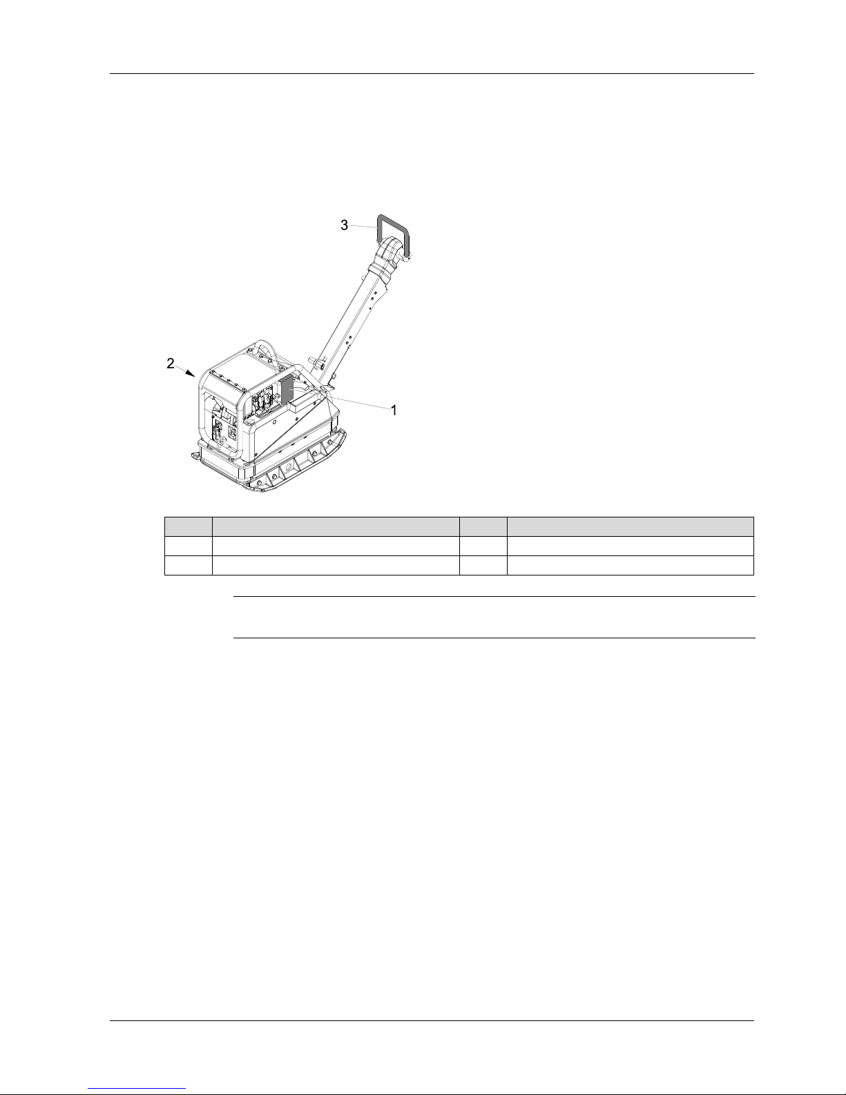
Item Designation Item Designation
1 Contact protection of exhaust system 3 Automatic central position of control handle
2 Belt guard
NOTICE
Always tighten loosened screwed connections with the prescribed torque setting.
Page 14
4 Safety and information labels
14 100_0202_ls_0006.fm
4 Safety and information labels
The following labels are located on the machine:
WARNING
Illegible symbols
Over time, labels and signs on the machines can become dirty or otherwise
unrecognizable.
Keep all safety, warning, and operating instructions on the machine in a legible
condition.
Replace damaged labels and signs immediately.
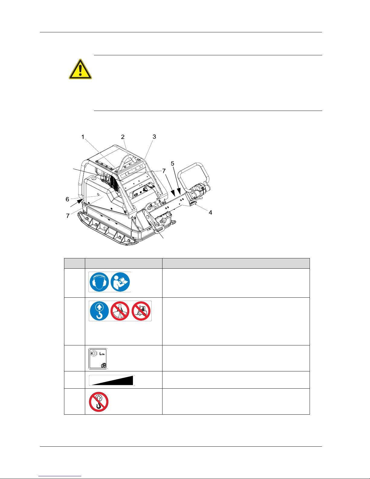
Item Label Description
1 Use personal protection equipment in order to avoid injuries
and health hazards:
Ear protection.
Read operator's manual.
2 Falling machines can cause serious injury.
Only lift machine at the central lifting point with certified
lifting gear and tackle (safety load hook).
Do not lift the machine on the central lifting point with an
excavator bucket.
Do not lift the machine on the central lifting point with a
forklift.
3 Guaranteed sound power level.
4 Start/Stop.
5 Falling machines can cause serious injury.
Do not lift the machine with the control hand le or center
pole.
8
9
9
0219175
0216633
0219259
0
2
2
0
0
0
0
Page 15

4 Safety and information labels
100_0202_ls_0006.fm 15
6 DPU45.., DPU55.. Warning.
Body parts can be crushed or cut off from rotating engine parts.
Do not touch the supp ort of the starting crank.
7 US Machines Warning.
8 Machines with electric starter Start/Stop.
9 Tie-down.
Item Label Description
0219261
WARNING
WARNUNG
ADVERTENCIA
ADVERTISSEMENT
0219176
Page 16

5 Setup and function
16 100_0202_sf_0006.fm
5 Setup and function
5.1 Standard package
The machine is delivered fully assembled and is ready for operation out of the box.
The standard package includes:
Vibratory plate
Starting crank (optional)
Operator's manual
5.2 Application areas
The vibratory plate is used for compacting soil. It is used in gardening and landscaping as well as civil
engineering, road construction, and paving.
5.3 Short description
The vibratory plate is a machine used to compact soils.
The vibration required for the compression is generated by the exciter firmly connected to the base plate.
This exciter is designed as a centrally mounted exciter with single-plane vibrations. Such a principle
allows for a modification in the vibration direction by turning the eccentric weights.
A variable transition between compression in travel speed, on the spot compaction and in reverse travel
is therefore possible. This process is controlled hydraulically with the control handle on the center pole
head.
The drive motor attached to the upper mass drives the exciter. The torque is firmly transferred through
the centrifugal clutch and the exciter V-belt.
At low engine speeds, the centrifugal clutch interrupts the force flow to the exciter and the reby allows a
flawless idling of the drive motor.
The automatic v-belt pulley combined with the centrifugal clutch ensures an optimal tensio n of the exciter
V-belt during operation and for relief of the exciter V-belt during offsetting or during transport of the
machine.
In addition, the automatic v-belt pulley automatically adjusts to the wear of the V-belt edges and thus
makes the entire drive system from the engine to the exciter maintenance-free.
The drill speed of the drive motor can be variably adjusted by remote control on the throttle lever and
locked into the idle position. The upper mass and base pla te are connected to ea ch other by 4 vibration
absorbing rubber metal buffers. This attenuation prevents a transmission of the very high frequen cies to
the upper mass. The functionality of the drive motor therefore remains preserve d, despite the high
compaction performance. The drive motor works according to the diesel pr inciple, is e lectrically started
via a gear and pinion starter, draws the combustion air through a dry-type air cleaner and is air-cooled.
To facilitate the starting process (when very cold, during manual start), the drive motor has a
decompression automation system. This causes the compression to be very low when starting to turn,
but to steadily increase after a few revolutions to then switch to full compression.
Operating hour meter (optional)
On the operating hour meter, the operating hours of the machine can be accurately read, thereby
allowing for better observance of the maintenance intervals.
Extension plates
For larger working areas, additional mounting plates are recommended.
Compatec – compaction display (optional):
The Compatec compaction display is attached to the battery cover and is within the operator’s line-ofsight. The display, which consists of eight light-adjusting LEDs, displays the relative compaction
progress by successively lighting up. When the number of illuminated LEDs no longer increases, this
means that no further compaction can be achieved with the machine. The operator can finish the work
and avoid unnecessary passes or over-compaction of the soil.
The overload display indicates if the machine is being operated on too hard of a surface. The operator
is notified of this through rapid flashing of all eight LED's.
Compatec – compaction display is suitable for all highly compactable and mixed-grained soils.
Page 17

5 Setup and function
100_0202_sf_0006.fm 17
Narrow protective frame (optional)
For narrow cable trenches, the narrow protective frame is recommended.
5.4 Versions
This operator's manual covers the following models:
NOTICE
Compatec – compaction display only supports soil compaction and does not replace the
professional measuring of soil density by an expert.
Versions Description
e Electric starter
h Operating hour meter
ap Extension plates
c Compatec – compaction display
s Narrow protective cage
Page 18
6 Components and operator's controls
18 100_0202_cp_0004.fm
6 Components and operator's controls
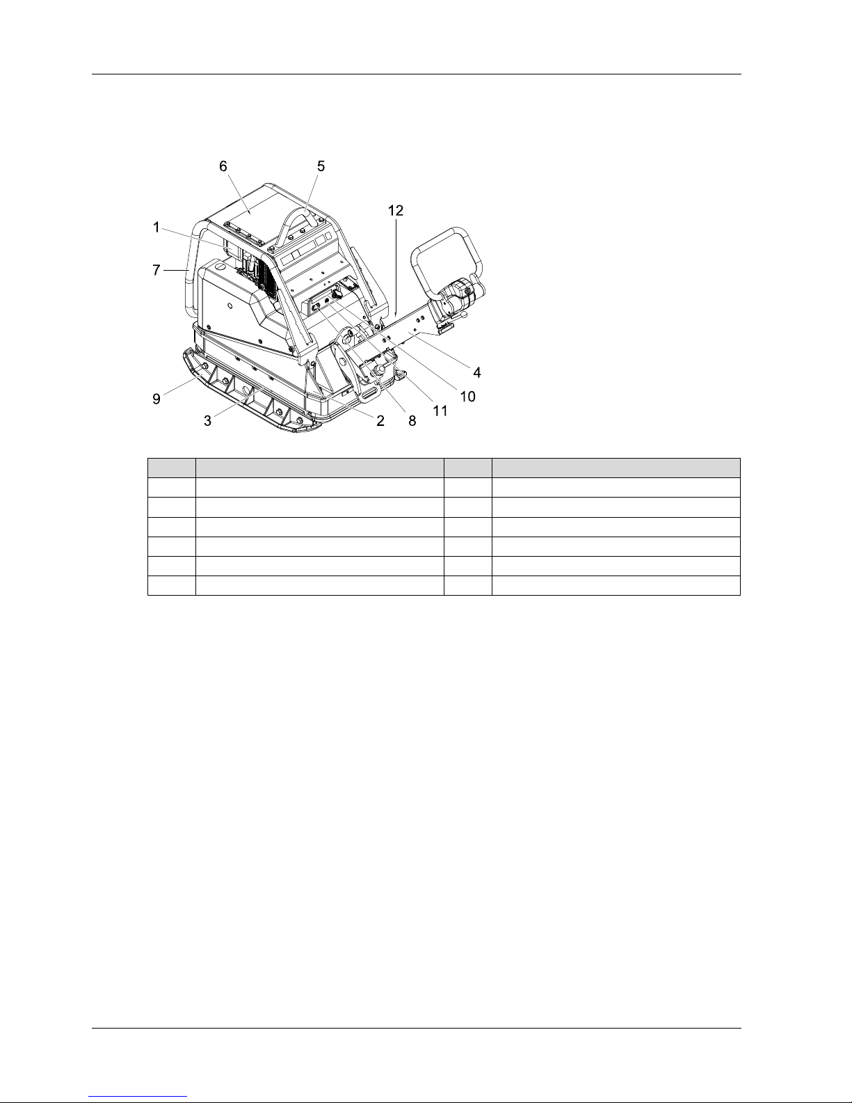
6.1 Components
Center pole
The optimal working height of the center pole can be adjusted by adjusting the threaded spindle.
Central lifting point
The central lifting point is used to lift the machine. It is located exactly in the center of gravity of the
machine, but can be offset to the rear for applications where the overall height is crucial.
Item Designation Item Designation
1 Drive motor 7 Protective frame
2 Upper mass 8 Operating hour meter (optional)
3 Base plate 9 Extension plates
4 Center pole 10 Compatec – compaction display (optional):
5 Central lifting point 11 Control lamp operation
6 Fuel tank 12 Nameplate
Page 19

6 Components and operator's controls
100_0202_cp_0004.fm 19
6.2 Operator's controls
Always keep the display and operator's controls on the machine clean, dry, and free of oil and grease.
Operator's controls, such as the ON/OFF switch, throttle control handles, etc. may not be locked,
manipulated or changed without permission.
Control handle
The control handle is used to continuously regulate the speed and travel direction.
Throttle lever
The drill speed of the drive motor can be continuously adjusted by remote control on the throttle lever
and locked into the idle position.
Decompression lever
The decompression lever may only be actuated to sta rt the m ach ine.
Jump start pin
The jump start pin facilitates connecting the jumper cable when jump starting.
Handle center pole lock
The handle center pole lock is used to release the center pole so that it can be returned to working
position.
Threaded spindle
The threaded spindle is used to set the optimal working height of the center pole.
Item Designation Item Designation
1 Control handle 5 Ignition lock
2 Throttle lever 6 Handle center pole lock
3 Decompression lever 7 Threaded spindle
4 Jump start pin
Page 20

7 Transport
20 100_0202_tr_0006.fm
7 Transport
7.1 Loading and transport
Carry out preparations
When loading and transporting, the center pole must be locked into place by engaging the center pole
lock in the vertical position.
WARNING
Improper handling may result in injury or serious material damage.
Please read and follow all safety instructions in this operator's manual.
DANGER
Danger from falling.
Falling machines can cause serious injury e.g. through crushing.
Only use suitable and tested lifting gear and tackle (safety load hooks) of sufficient
lifting capacity.
Only lift the machine from the central lifting point.
Reliably secure the machine to the lifting gear.
Do not lift the machine on the central lifting point with a forklift or excavator bucket.
Do not lift the machine at the control handle.
Evacuate danger zone while lifting, do not stop under suspended loads.
WARNING
Risk of fire and explosion from fuel.
Escaping fuel may catch fire and cause serious burns.
Lift and transport the machine upright.
CAUTION
If the central lifting point of the machine is fixed offset, the machine is no longer in the
center of gravity and may tilt to the rear.
NOTICE
Wacker Neuson recommends emptying the fuel tank prior to transport.
Item Designation Item Designation
1 Center pole 2 Handle center pole lock
2
1
Page 21

7 Transport
100_0202_tr_0006.fm 21
Lifting and lashing down the machine
1. To lift the motor, hang suitable tackle at the central lifting point.
2. Carefully load machine into or onto a stable means of transport.
3. After loading the machine, lash down the machine to prevent it from rolling off, slipping, or tipping
over. Attach tie-down lugs to the designated lashing points.
NOTICE
Appoint a specialist flagman for a safe lifting operation.
Item Designation Item Designation
1 Central lifting point 2 Tie-down lugs
Item Designation
1Belt
2
2
1
Page 22

8 Operation and use
22 100_0202_op_0009.fm
8 Operation and use
8.1 Before commissioning
8.1.1 Inspection before commissioning
Check the machine and components for damage. In the event of visible damag e, do not operate the
machine and immediately contact a Wacker Neuson dealer.
Ensure that loose packaging material has been removed from the machine.
Check fuel level.
Check the engine oil level.
Check hydraulic oil level.
Check the fuel lines for leak tightness.
Check to ensure the screwed connections are firmly seated.
8.1.2 Set center pole
The optimal working height of the center pole can be adjusted by adjusting the threaded spindle.
8.2 Notes about operation
WARNING
Improper handling may result in injury or serious material damage.
Please read and follow all safety instructions in this operator's manual.
NOTICE
Perform control procedures according to the Maintenance chapter. If necessary, top off
missing fuel, lubricants and coolants, see chapterTechnical Data.
Item Designation Item Designation
1 Center pole 2 Threaded spindle
WARNING
Danger of tipping
There is a serious risk of injury from slipping or tipping over of the machine.
Near edges, at least 2/3 of the machine must be on a load-bearing surface.
Turn off the machine and lift it back onto a load-bearing surface.
WARNING
Health hazard from exhaust fumes
The exhaust fumes of this engine contain chemicals, which the state of California
knows can cause cancer, birth defects or other reproductive damage.
2
1
Page 23

8 Operation and use
100_0202_op_0009.fm 23
Operation on sloped surfaces
Always stand above the machine within the area of a slope.
Only approach gradients from below (a gradient that can be easily driven up can also be driven down
without any risk).
Do not stand in the direction of descent of the machine.
Do not exceed the maximum allowable slanting position (see Technical Data) chapter.
Only operate the machine for a short time in maximum allowable slanting position.
Vibrating sett paving (paving stones)
When compacting interlocking paving stones, Wacker Neuson r ecommends the application of the sliding
mechanism in order to avoid damage to the machine and compaction material. See chapter
Accessories.
8.3 Commissioning
8.3.1 Commissioning the machine (manual start)
1. Put the throttle lever in the full throttle position.
2. Pull the decompression lever up.
NOTICE
If the maximum permissible slanting position is exceeded, this results in a failure of the
engine lubrication and therefore inevitably causes a defect of important engine parts.
DANGER
Fire hazard
Jumper cable sprays are highly flammable; they can ignite and cause severe burns.
Do not use jumper cable sprays.
WARNING
The starting crank can cause serious injuries.
Do not use any defective starting cranks.
Only use a clean starting crank.
Item Designation Item Designation
1 Throttle lever 3 Starting crank support
2 Decompression lever
1
2
3
Page 24

8 Operation and use
24 100_0202_op_0009.fm
3. Stand next to the machine.
4. Insert the starting crank into the support.
5. Grab the crank handle with one hand. Support yourself on the protective cage with the other hand.
6. First slowly turn the starting crank counter-clockwise until the ratchet snaps into place. Then turn
powerfully with increasing speed.
7. Pull the starting crank out of the support.
8. Put the throttle lever in the idle position and lock into place.
9. Suspend the starting crank in the provided bracket.
10.Allow the machine to warm up by idling for a few minutes.
NOTICE
In this position, the decompression automation system audibly locks into place and the
engine is ready to start.
NOTICE
After the decompression automation system locks into place, give starting crank
revolutions are required until the engine can be re-compressed and strike.
NOTICE
Once the engine starts, the decompression lever disengages (the maximum possible
speed must be reached), the engine starts and the vibration starts.
The friction connection between the engine and starting crank must be ensured through
the anti-twist holding of the crank handle and rapid cranking and may not be interrupted
during the starting process under any circumstances.
If a recoil occurs during the starting process from not turning the crank hard enough, the
connection between the crank web and starting dog is disengaged via the crank handle
due to the short backturn.
When making another attempt at starting, wait until the engine comes to a standstill. Do
not actuate the decompression lever when the engine is running.
Page 25

8 Operation and use
100_0202_op_0009.fm 25
8.3.2 Commissioning the machine in the cold (manual start)
1. Move the decompression lever to the center position.
2. Crank the engine with the starting crank counter-clockwise until it noticeably rotates more easily (10
- 20 crank revolutions).
3. Press the lever of the mechanical oil pressure monitoring for 15 seconds.
4. Fill motor oil in the metering device up to the upper rim.
5. Seat the cover and forcibly press it in.
6. Pull the decompression lever up until the detent.
7. Then start the engine immediately. See the chapter "Commissioning the machine (manual start).”
NOTICE
For temperatures below -5 °C, generally freely turn the engine.
Item Designation Item Designation
1 Decompression lever 3 Metering device
2 Lever for the oil pressure monitoring
NOTICE
Remove dirt in the area of the metering device cover and remove the cover.
NOTICE
Two fillings in succession are necessary.
1
3
2
Page 26

8 Operation and use
26 100_0202_op_0009.fm
8.3.3 Commissioning the machine (electric start)
1. Put the throttle lever in the full throttle position.
2. Insert the ignition switch key into the ignition lock and turn to the right. The charge control lamp will
illuminate and the acoustic signal will sound.
3. Turn ignition switch key to position ll. As soon as the engine starts, release the ignition switch key.
4. Put the throttle lever in the idling position.
5. Allow the machine to warm up by idling for a few minutes.
Item Designation Item Designation
1 Throttle lever 3 Ignition lock
2 Decompression lever 4 Charge control lamp
NOTICE
In extreme cold, actuate the decompression lever as well and push it up. In this position,
the decompression automation system audibly locks into place and the engine is ready to
start.
NOTICE
As soon as the engine starts, the vibration will begin.
Page 27

8 Operation and use
100_0202_op_0009.fm 27
Machine with Compatec – compaction display (optional)
1. During the first few seconds after starting the machine, a light progress bar appears on the display
unit.
2. LEDs light up starting from left to right.
3. All LEDs will briefly light up again at reduced brightness.
4. The sensor is thus successfully tested and the display is ready for operation.
8.4 Operation
In accordance with the intended purpose, the operator should stand behind the machine.
Guide and steer machine using the control handle.
8.4.1 Select the travel direction
1. Put the throttle lever in the full throttle position.
2. Select travel direction and speed with the control handle.
Item Designation Item Designation
1 Display unit 2 LEDs/light progress bar
NOTICE
If all LEDs light up, the system is fault-free. The LEDs will then switch off one after the
other.
NOTICE
If all LEDs permanently light after initialization, the sensor has not been successfully
tested; see troubleshooting chapter.
Item Designation Item Designation
1 Forward 2 Reverse
1
2
1
2
Page 28

8 Operation and use
28 100_0202_op_0009.fm
8.4.2 Reading Compatec – compaction display
This display roughly indicates the progress of the compaction.
The number of LEDs lit is proportional to the soil density, more illuminated LEDs corresponds to a
higher soil density.
8.5 Decommissioning
8.5.1 Decommissioning the machine (manual start)
1. Put the throttle lever back to the detent.
2. The engine comes to a standstill.
NOTICE
To protect the machine, the display unit warns the operator of over -compaction by quickly
flashing all LEDs. The brightness of the LED automatically adjusts to the light conditions
of the working area.
NOTICE
It is possible to detect missing spots (non-compactable material) if the spot is longer th an
one meter.
In the case of abrupt change from high to low-compacted soil (or vice versa), there is a
slow increase or decrease of the LEDs.
NOTICE
Do not decommission the machine with the decompression lever, since this inevitably
leads to damage to the machine or engine.
Item Designation
1 Throttle lever
1
Page 29

8 Operation and use
100_0202_op_0009.fm 29
8.5.2 Decommissioning the machine (electric start)
1. Put the throttle lever back to the detent.
2. After the engine has come to a standstill, turn the ignition switch key in the ignition lock to the left and
pull out. The charge control lamp will go out and the acoustic signal will be silent.
Item Designation Item Designation
1 Throttle lever 3 Charge control lamp
2 Ignition lock
NOTICE
The Compatec compaction display automatically switches itself off once the ignition switch
key is pulled out. The display unit has no "sleep function." Continuous operation without
engine operation leads to battery drainage.
1
3
2
Page 30

9 Maintenance
30 100_0202_mt_0008.fm
9 Maintenance
WARNING
Improper handling may result in injury or serious material damage.
Please read and follow all safety instructions in this operator's manual.
WARNING
Danger of poisoning from exhaust fumes.
Exhaust fumes contain poisonous carbon monoxide, which ca n lead to un consciousness
or to death.
Only perform maintenance jobs with the engine switched off and the machine
decommissioned.
WARNING
Risk of injury from uncontrolled starting of the machine and moving parts.
Only perform maintenance jobs with the engine switched off and the machine
decommissioned.
WARNING
Risk of fire and explosion from fuel and fuel vapors.
Fuel and fuel vapors may ignite or catch fire and cause serious burns.
Do not smoke.
Do not refuel near open flames.
Switch off the engine and allow to cool before refueling.
WARNING
Warning of hot surfaces
The muffler and engine can become extremely hot, which can lead to severe skin burns if
touched.
Always allow the engine to cool down completely after use.
If the cool-down phase cannot be adhered to (e.g. due to an emergency), use heat-
resistant protective gloves.
WARNING
Risk of injury due to non-existent or non-functioning safety devices.
Only oper at e th e ma ch ine if the safe ty de vice s ar e pr op e rly fixe d an d functioning.
Do not modify or remove safety devices.
Page 31

9 Maintenance
100_0202_mt_0008.fm 31
9.1 Maintenance table
9.2 Maintenance jobs
Maintenance jobs Daily h/year Weekly Monthly
Clean the machine
Visual inspection for completeness
Visual inspection for damage
Check the engine oil level*
Replace the engine oil* 25 h/250 h
Replace the engine oil filter* 25 h/250 h
Clean, set, repair, replace the injection nozzles* 1500 hours
Clean, set, repair the injection valve* 3000 hours
Replace the fuel filter* 500 hours
Check water trap*
Check the intake area of the combustion air*
Check air cleaner service indicator*
Clean the air cleaner cartridge* 500 hours
Check the tapped clearance** 25 h/250 h
Check the exciter oil level
Replace the exciter oil 250 h/1/2
year
Check hydraulic oil level**
Check hydraulic hose lines** 125 hours
Check / replace the V-belt
Check the rubber buffer** 125 hours
Check the to ensure the screwed connections are firmly
seated
Re-lubricate the threaded spindle and ratchet pin
*
Note the engine operator's manual.
**
Have this work performed by the service department of your Wacker Neuson contact partner.
CAUTION
Health risk from fuel, lubricants and coolants.
Do not inhale fuel, lubricants, coolants or vapors.
Avoid contact of skin or eyes with fuel, lubricants and coolants.
Page 32

9 Maintenance
32 100_0202_mt_0008.fm
Carry out preparations:
1. Place the machine on a level surface.
2. Decommissioning the machine.
3. Allow engine to cool down.
Check the fuel level and top off
1. Fold the cover to the side.
2. Remove dirt accumulation within the range of the fuel filler neck.
3. Open the fuel filler neck
4. Check the fuel level by visual check
5. If necessary, top off the fuel with a clean filling container.
Fuel type See chapter Technical Data.
6. Tightly seal the tank cap.
WARNING
Risk of fire and explosion from fuel and fuel vapors.
Do not smoke.
Do not refuel near open flames.
Switch off engine and allo w to cool be fo re refueling. Only refuel in a well-ventilated
vicinity.
Item Designation
1 Fuel filler neck
NOTICE
Only fill the fuel tank to the bottom edge of the filler neck.
1
Page 33

9 Maintenance
100_0202_mt_0008.fm 33
Check water trap
1. Dismantle the plate cover.
2. Loosen the hexagonal bolt 2-3 by revolutions.
3. Collect the escaping drops in a transparent container.
4. Once only fuel is escaping, tighten the hexagonal bolt.
5. Attach the plate cover.
Cleaning the machine
1. After cleaning, check the cable, hoses, utility lines and hardware for leaks, loose connections, chafe
marks and other damage.
2. Immediately eliminat e de te cte d dama ge .
Screwed connections
For the vibratory plates, the screwed connections must be regularly checked for a firm seat.
Check and replace V-belt and belt stabilizer
Item Designation Item Designation
1 Plate cover 2 Hexagonal bolt
NOTICE
Since water is specifically heavier than diesel fuel, the water will exit first and then the fuel.
This can be seen by a clear separating line.
WARNING
Risk of fire and explosion when using flammable cleaning agents.
Do not clean the machine and elements with gasoline or other solvents.
NOTICE
Penetrating water can damage the engine, electrical operator's controls or components of
the machine. Do not aim high pressure washer directly at air intake area and electrical
elements.
Page 34

9 Maintenance
34 100_0202_mt_0008.fm
1. Disassemble the belt guard.
2. Check the condition of the V-belt and the belt stabilizer. If the V-belt width should be less than 15.5
mm or if there is visible damage, this must be replaced.
3. Loosen the screw.
4. Remove the mushroom-shaped plate, bellville lock washers and gasket.
5. Pull the v-belt pulley (engine) away from the machine and the V-belt will loosen.
6. Push the V-belt down until it slips away from the v-belt pulley (exciter).
7. Push the V-belt up and out.
8. Place the new V-belt around the v-belt pulley (exciter) and press over the v-belt pulley (engine).
9. Push the v-belt pulley (engine) inwards towards the machine.
10.Screw the gasket, bellville lock washers and mushroom-shaped plate back on with the screw. The
torque setting is 49 Nm.
11.Seat the belt guard and screw tight. The torque setting is 25 Nm.
Replace the exciter oil and check the oil level
Item Designation Item Designation
1 Belt guard 2 Screw
NOTICE
Do not oil or grease coupling parts, as this could damage the graphite bushings and the
friction linings and V-belt could slip.
NOTICE
Move the V-belt back and forth to check whether this is seated properly in both v-belt
pulleys.
NOTICE
Due to the application of the automatic centrifugal clutch, it is not necessary to re-tension
the V-belt.
DANGER
Risk of scalding
Use caution when draining hot oil.
2
Page 35

9 Maintenance
100_0202_mt_0008.fm 35
1. Tip the machine to the side of the filler boring and support it.
2. Place an appropriate collecting container below the filler boring.
3. Remove dirt accumulation within the range of the filler boring.
4. Unscrew the screw plug from the filler boring and allow the waste oil to drain completely.
5. Tip the machine to the other side and support it.
6. Fill new oil (see chapterTechnical Data for the exciter oil type and volume) in the filler boring. Use an
appropriate and clean filling container.
7. Place the machine level on the ground.
8. Screw the screw plug with seal ring into the filler boring. The torque setting is 100 Nm.
NOTICE
Perform oil change and oil level check with warm exciter oil. Machine must not be in use
and must be level.
Item Designation Item Designation
1 Screw plug 2 Filler boring
NOTICE
Lay an impermeable film on the working surface to protect against escaping oil.
NOTICE
Collect escaping or overflowing oil and dispose of with the waste oil in an environmentally
friendly manner in accordance with the existing rules and regulations of the legislative
body.
NOTICE
Only fill with the prescribed volume of oil.
1, 2
Page 36

9 Maintenance
36 100_0202_mt_0008.fm
Changing the starter battery
DANGER
Risk of electric shock
Risk of injury from simultaneous touching of positive terminal and ground.
Always disconnect the negative terminal first.
Always connect the positive terminal first.
Always cover one terminal to prevent accidental short circuits.
Hazard from fuel, lubricants and coolants - acid splashes.
NOTICE
Only Wacker Neuson use starter batteries.
Only replace defective starter batteries with Wacker Neuson starter batteries. See
Technical Data section.
Only the Wacker Neuson starter battery is vibration proof and therefore suitable for the
high vibration exposure.
Item Designation Item Designation
1 Protective frame 3 Starter battery
2 Battery cover
3
1
2
Page 37

9 Maintenance
100_0202_mt_0008.fm 37
1. Remove the protective cage.
2. Remove the battery cover and disconnect the positive terminal cover.
3. Disconnect starter battery.
4. Lift out defective starter battery and remove battery protection support.
5. Attach battery protection support to the new starter battery.
6. Insert the new starter battery.
7. Attach the positive terminal cover.
8. Connect starter battery.
9. Attach the battery cover.
10.Attach the protective cage.
NOTICE
First disconnect negative terminal, then positive terminal.
NOTICE
First connect positive terminal, then the negative terminal.
Item Designation Item Designation
1 Positive terminal cover 2 Coiled helix cable
NOTICE
Before installing the battery cover, ensure that the positive terminal cover is attached.
When assembling the starter battery, pay attention to the coiled helix cable.
2
1
Page 38

10 Troubleshooting
38 100_0202_ts_0008.fm
10 Troubleshooting
10.1 Fault table
10.2 Perform jump start with donor starter battery
If the starter battery of the machine is discharged and the engine does not star t, a jump-start with a donor
battery is possible.
DANGER
Danger to life from unauthorized troubleshooting.
If faults occur with this machine that are not described in this manual, contact the
manufacturer. Do not eliminate the faults independently.
Fault Possible causes Remedial measure
The reverse travel speed is too low. Not enough hydraulic oil in the
center pole head.
Top off the hydraulic oil.
The forward travel speed is too low. Too much hydraulic oil in the center
pole head.
Correct the oil level accordingly.*
Air in the hydraulic control system. Bleed.*
No travel speed. Mechanical fault. Have the machine repaired.*
Loss of hydraulic oil. Leaks Have the machine repaired.*
Motor will not start. Defective ignition lock. Have the machine repaired.*
Defective starter motor.
Discharge starter battery. Charge starter battery.
Low oil level Top up oil and actuate valve hood
on the oil filter housing.
The charge control lamp will not go
out.
Defective alternator. Have the machine repaired.*
The acoustic signal will not stop
sounding.
Defective voltage regulator.
Compaction display (optional):
If all LEDs permanently flash after
initialization, the sensor has not
been successfully tested.
Switch-on with the engine running. Have the machine repaired.*
Sensor is defective.
*
Have this work performed by the service department of your Wacker Neuson contact partner.
WARNING
Risk of explosion from explosive gas.
Risk of injury from splashing acid.
Wear safety glasses and protective gloves.
The donor battery and starter battery of the machine must have the same voltage (12
V).
Avoid short circuit from reverse polarity (plus to plus, minus to minus).
Use correct sequence when connecting the jumper cables.
NOTICE
Use only insulated jumper cables with a conductor cross-section of at least 16 mm².
Page 39

10 Troubleshooting
100_0202_ts_0008.fm 39
1. Pull out jump start pin and conne ct cl am p ing ton gs of the red jumper cable to the jump start pin.
2. Connect the second clamping tongs of the red jumper cable to the positive terminal of the donor
battery.
3. Connect clamping tongs of the black jumper cable to the negative terminal of the donor battery.
4. Connect the second clamping tongs of the black jumper cable to a grounding point of the machine,
e.g. at the engine block.
Perform jump start
5. Start engine.
If the engine does not start after a maximum of 15 seconds, stop the starting process and contact
your Wacker Neuson contact person.
6. Run engine for a few minutes.
Disconnect the jumper cable
7. Disconnect clamping tongs of the black jumper cable from the grounding point of the machine.
8. Disconnect the second clamping tongs of the black jumper cable from the donor battery.
9. Disconnect the clamping tongs of the red jumper cable from the jump start pin and ensure that the
jump start pin is completely retracted.
10.Disconnect the second clamping tongs of the red jumper cable from the positive termina l of the donor
battery.
Item Designation Item Designation
1 Jump start pin 4 Negative terminal of the donor battery
2 Negative terminal at the grounding point 5 Positive terminal of the donor battery
3 Black jumper cables 6 Red jumper cables
Page 40

11 Disposal
40 100_0000_0007.fm
11 Disposal
11.1 Disposal of batteries
The machine contains one or more batteries or rechargeable batteries (hereinafter referred to as "the
battery"). Proper disposal of the battery prevents negative effects on individuals and the environment,
follows the specific treatment of pollutants, and ensures the recycling of useful raw materials.
For customers in EU countries
This battery is subject to the European Directive on (old) batteries and (old) rechargeable batteries, and
the respective national laws. The battery directive outlines the framework for an EU-wide treatmen t of
batteries.
The battery is marked with the following symbol of a crossed-out garbage bin . Below this
symbol, there is also the name of the pollutants contained therein, i.e. "Pb" for lead, "Cd"
for cadmium, and "Hg" for mercury.
Batteries may not be disposed of with nor mal household waste! As an end-user, yo u
may only dispose of used batteries via the manufacturer or specially equipp ed colle ction
facilities (statutory obligation to return); the delivery is free. Retailers and manufacturers are obliged to
take back these batteries and properly recycle them or dispose of them as hazardous waste (legal
obligation).
Batteries obtained through Wacker Neuson can be retur ned to Wacker Neuson free of charge after use.
If the batteries cannot be personally returned to a Wacker Neuson branch, there are instructions in the
sales contract or in the Terms and Conditions of the location where they were purchased.
For customers in other countries
Wacker Neuson recommends that you do not dispose of the battery in normal household waste but
rather in a separate, environmentally friendly collection fa cili ty. Nationa l laws m ay also ha ve provisions
for the separate disposal of batteries. Disposal of the battery in accordance with current national
guidelines must be assured.
Page 41

12 Accessories
100_0202_ac_0004.fm 41
12 Accessories
A wide range of accessories is offered for the machine.
More information about the individual accessories can be found online at www.wackerneuson.com.
Extension plates
For the machine, the extension plates are available in different widths with which the operating width of
the machine can be expanded or reduced.
Sliding mechanism
Sliding mechanisms offer optimal protection again st damage to the sett paving (paving stone) surface,
which is especially required for surface-coated types of paving.
Starting crank
DPU4545 and DPU5545 - short tool shank of the starting crank.
DPU6555 - long tool shank of the starting crank.
Starting crank holder
A starting crank holder can be attached to store the starting crank on the machine.
Undercarriage
An undercarriage is offered for easier transport on the construction site.
CAUTION
Accessories and spare parts that do not originate from Wacker Neuson ca n in cr ea se the
risk of injury and possible damage to the machine.
The use of other accessories and spare parts that do not originate from
Wacker Neuson shall cancel any liability.
Page 42

13 Technical data
42 100_0202_td_0015.fm
13 Technical data
13.1 DPU4545
Designation Unit DPU4545H DPU4545He DPU4545Heh
Item number 5100009661 5100016951 5100009659
Centrifugal force kN 45.00 45.00 45.00
Oscillations Hz 69 69 69
1/min 4,140 4,140 4,140
Compaction performance* m
2
/h 910 910 910
Travel speed m/min 25.0 25.0 25.0
Gradeability % 57.7 57.7 57.7
Length (center pole in working
position)
mm 1,661 1,661 1,661
Width mm 604 604 604
Height mm 1,308 1,308 1,308
Operating weight kg 402.0 423.0 423.0
Ground clearance mm 790 – 914 790 – 914 790 – 914
Electrical load rating ** kW 6.4 6.4 6.4
Nominal speed 1/min 2,850 2,850 2,850
Exciter oil volume l 0.75 0.75 0.75
Exciter oil type
SAE 75W-90 SAE 75W-90 SAE 75W-90
Hydraulic oil volume l 0.5 0.5 0.5
Type of hydraulic oil MR 520 MR 520 MR 520
Storage temperature range °C -15 – +40 -15 – +40 -15 – +40
Operating temperature range °C -15 – +40 -15 – +40 -15 – +40
Sound pressure level
At location of operation L
pA
dB(A) 94 94 94
Standards EN 500-4
Sound power level L
wa
measured
guaranteed
dB(A)
107
108
107
108
107
108
Standards EN 500-4
Vibration total value a
hv
m/s
2
< 2.5 < 2.5 < 2. 5
Standards EN 500-4
Uncertainty of measurement of
the vibration total value a
hv
m/s
2
0.5 0.5 0.5
*
Depending on the soil properties.
**
Corresponds to the net installed power according to directive 2000/14/EC.
Page 43

13 Technical data
100_0202_td_0015.fm 43
Designation Unit DPU4545
Hec
DPU4545
Hech
DPU4545
Heh US
DPU4545
Hech US
Item number 5100016953 5100015429 5100009660 5100016952
Centrifugal force kN 45.00 45.00 45.00 45.00
Oscillations Hz 69 69 69 69
1/min 4,140 4,140 4,140 4,140
Compaction performance* m
2
/h 910 910 910 910
Travel speed m/min 25.0 25.0 25.0 25.0
Gradeability % 57.7 57.7 57.7 57.7
Length (center pole in working
position)
mm 1,661 1,661 1,661 1,661
Width mm 604 604 604 604
Height mm 1,308 1,308 1,308 1,308
Operating weight kg 424.0 425.0 423.0 423.0
Ground clearance mm 790 – 914 790 – 914 790 – 914 790 – 914
Electrical load rating ** kW 6.4 6.4 6.4 6.4
Nominal speed 1/min 2,850 2,850 2,850 2,850
Exciter oil volume l 0.75 0.75 0.75 0.75
Exciter oil type
SAE 75W-90 SAE 75W-90 SAE 75W-90 SAE 75W-90
Hydraulic oil volume l 0.5 0.5 0.5 0.5
Type of hydraulic oil MR 520 MR 520 MR 520 MR 520
Storage temperature range °C -15 – +40 -15 – +40 -15 – +40 -15 – +40
Operating temperature range °C -15 – +40 -15 – +40 -15 – +40 -15 – +40
Sound pressure level
At location of operation L
pA
dB(A) 94 94 94 94
Standards EN 500-4
Sound power level L
wa
measured
guaranteed
dB(A)
107
108
107
108
107
108
107
108
Standards EN 500-4
Vibration total value a
hv
m/s
2
< 2.5 < 2.5 < 2.5 < 2.5
Standards EN 500-4
Uncertainty of measurement
of the vibration total value a
hv
m/s
2
0.5 0.5 0.5 0.5
*
Depending on the soil properties.
**
Corresponds to the net installed power according to directive 2000/14/EC.
Page 44

13 Technical data
44 100_0202_td_0015.fm
13.2 Combustion engine
Designation Unit
Manufacturer Hatz
Type of engine 1D42S-151 1D42S-152 1D42S-177
Combustion method Four-cycle Four-cycle Four-cycle
Cooling Air cooling Air cooling Air cooling
Cylinders 1 1 1
Displacement cm³ 445 445 445
Max. slanting position ° 30 30 30
Fuel type Diesel Diesel Diesel
Fuel consumption l/h 1.6 1.6 1.6
Tank capacity l 5.0 5.0 5.0
Oil specification SAE 10W40 SAE 10W40 SAE 10W40
Max. oil filling l 1.1 1.1 1.1
Max. performance kW 7.0 7.0 7.0
Standards ISO 3046 IFN
Drill speed (max. output) 1/min 3,600 3,600 3,600
Electrical load rating kW 6.4 6.4 5.8
Standards ISO 3046 IFN
Nominal speed 1/min 2,850 2,850 2,850
Rated power output kW 4.9 4.9 4.9
Standards ISO 3046 IFN
Operating speed 1/min 3,000 3,000 3,000
Standards ISO 3046 IFN
Upper engine speed without
load
1/min 3,060 3,060 3,060
Air cleaner Dry-type air cleaner Dry-type air cleaner Dry-type air cleaner
Starter type Manual crank start Electric starter Electric starter
Battery voltage V – Special Wacker Neuson starter battery for
vibratory plates, 12 V, 45 Ah
Battery capacity (nominal
value)
Ah –
Page 45

14 Technical data
100_0202_td_0016.fm 45
14 Technical data
14.1 DPU5545
Designation Unit DPU5545H DPU5545He DPU5545
Heh
DPU5545
Heap
Item number 5100009656 5100016947 5100009652 5100016949
Centrifugal force kN 55.00 55.00 55.00 55.00
Oscillations Hz 69 69 69 69
1/min 4,150 4,150 4,150 4,150
Compaction performance* m
2
/h 980 980 980 1,170
Travel speed m/min 27.0 27.0 27.0 26.0
Gradeability % 57.7 57.7 57.7 57.7
Length (center pole in working
position)
mm 1,661 1,661 1,661 1,661
Width mm 604 604 604 750
Height mm 1,308 1,308 1,308 1,308
Operating weight kg 399.0 424.0 424.0 447.0
Ground clearance mm 790 – 914 790 – 914 790 – 914 790 – 914
Electrical load rating ** kW 6.4 6.4 6.4 6.4
Nominal speed 1/min 2,850 2,850 2,850 2,850
Exciter oil volume l 0.75 0.75 0.75 0 .7 5
Exciter oil type SAE 75W-90 SAE 75W-90 SAE 75W-90 SAE 75W-90
Hydraulic oil volume l 0.5 0.5 0.5 0.5
Type of hydraulic oil MR 520 MR 520 MR 520 MR 520
Storage temperature range °C -15 – +40 -15 – +40 -15 – +40 -15 – +40
Operating temperature range °C -15 – +40 -15 – +40 -15 – +40 -15 – +40
Sound pressure level
At location of operation L
pA
dB(A)
94 94 94 94
Standards EN 500-4
Sound power level L
wa
measured
guaranteed
dB(A)
107
108
107
108
107
108
107
108
Standards EN 500-4
Vibration total value a
hv
m/s
2
< 2.5 < 2.5 < 2.5 < 2.5
Standards EN 500-4
Uncertainty of measurement of
the vibration total value a
hv
m/s
2
0.5 0.5 0.5 0.5
*
Depending on the soil properties.
**
Corresponds to the net installed power according to directive 2000/14/EC.
Page 46

14 Technical data
46 100_0202_td_0016.fm
Designation Unit DPU5545
Hehap
DPU5545
Hec
DPU5545
Hech
Item number 5100009654 5100016950 5100009655
Centrifugal force kN 55.00 55.00 55.00
Oscillations Hz 69 69 69
1/min 4,150 4,150 4,150
Compaction performance* m
2
/h 1,170 980 980
Travel speed m/min 26.0 27.0 27.0
Gradeability % 57.7 57.7 57.7
Length (center pole in working
position)
mm 1,661 1,661 1,661
Width mm 750 604 604
Height mm 1,308 1,308 1,308
Operating weight kg 447.0 425.0 425.0
Ground clearance mm 790 – 914 790 – 914 790 – 914
Electrical load rating ** kW 6.4 6.4 6.4
Nominal speed 1/min 2,850 2,850 2,850
Exciter oil volume l 0.75 0.75 0.75
Exciter oil type SAE 75W-90 SAE 75W-90 SAE 75W-90
Hydraulic oil volume l 0.5 0.5 0.5
Type of hydraulic oil MR 520 MR 520 MR 520
Storage temperature range °C -15 – +40 -15 – +40 -15 – +40
Operating temperature range °C -15 – +40 -15 – +40 -15 – +40
Sound pressure level
At location of operation L
pA
dB(A) 94 94 94
Standards EN 500-4
Sound power level L
wa
measured
guaranteed
dB(A)
107
108
107
108
107
108
Standards EN 500-4
Vibration total value a
hv
m/s
2
< 2.5< 2.5< 2.5
Standards
EN 500-4
Uncertainty of measurement of
the vibration total value a
hv
m/s
2
0.5 0.5 0.5
*
Depending on the soil properties.
**
Corresponds to the net installed power according to directive 2000/14/EC.
Page 47

14 Technical data
100_0202_td_0016.fm 47
Designation Unit DPU5545Hech US DPU5545Heh US
Item number 5100016948 5100009653
Centrifugal force kN 55.00 55.00
Oscillations Hz 69 69
1/min 4,150 4,150
Compaction performance* m
2
/h 980 980
Travel speed m/min 27.0 27.0
Gradeability % 57.7 57.7
Length (center pole in working
position)
mm 1,661 1,661
Width mm 604 604
Height mm 1,308 1,308
Operating weight kg 424.0 424.0
Ground clearance mm 790 – 914 790 – 914
Electrical load rating ** kW 6.4 6.4
Nominal speed 1/min 2,850 2,850
Exciter oil volume l 0.75 0.75
Exciter oil type SAE 75W-90 SAE 75W-90
Hydraulic oil volume l 0.5 0.5
Type of hydraulic oil MR 520 MR 520
Storage temperature range °C -15 – +40 -15 – +40
Operating temperatu r e ra n ge °C -15 – +40 -15 – +40
Sound pressure level
At location of operation L
pA
dB(A) 94 94
Standards EN 500-4
Sound power level L
wa
measured
guaranteed
dB(A)
107
108
107
108
Standards EN 500-4
Vibration total value a
hv
m/s
2
< 2.5 < 2.5
Standards EN 500-4
Uncertainty of measurement of
the vibration total value a
hv
m/s
2
0.5 0.5
*
Depending on the soil properties.
**
Corresponds to the net installed power according to directive 2000/14/EC.
Page 48

14 Technical data
48 100_0202_td_0016.fm
14.2 Combustion engine
Designation Unit
Manufacturer Hatz
Type of engine 1D42S-151 1D42S-152 1D42S-177
Combustion method Four-cycle Four-cycle Four-cycle
Cooling Air cooling Air cooling Air cooling
Cylinders 1 1 1
Displacement cm³ 445 445 445
Max. slanting position ° 30 30 30
Fuel type Diesel Diesel Diesel
Fuel consumption l/h 1.6 1.6 1.6
Tank capacity l 5.0 5.0 5.0
Oil specification SAE 10W40 SAE 10W40 SAE 10W40
Max. oil filling l 1.1 1.1 1.1
Max. performance kW 7.0 7.0 7.0
Standards ISO 3046 IFN
Drill speed (max. output) 1/min 3,600 3,600 3,600
Electrical load rating kW 6.4 6.4 5.8
Standards ISO 3046 IFN
Nominal speed 1/min 2,850 2,850 2,850
Rated power output kW 4.9 4.9 4.9
Standards ISO 3046 IFN
Operating speed 1/min 3,000 3,000 3,000
Standards ISO 3046 IFN
Upper engine speed without
load
1/min 3,060 3,060 3,060
Air cleaner Dry-type air cleaner Dry-type air cleaner Dry-type air cleaner
Starter type Manual crank start Electric starter Electric starter
Battery voltage V – Special Wacker Neuson starter battery for
vibratory plates, 12 V, 45 Ah
Battery capacity (nominal
value)
Ah –
Page 49

15 Technical data
100_0202_td_0017.fm 49
15 Technical data
15.1 DPU6555
Designation Unit DPU6555
H
DPU6555
Hs
DPU6555
He
DPU6555
Heap
Item number 5100009651 5100015773 5100016940 5100016943
Centrifugal force kN 65.00 65.00 65.00 65.00
Oscillations Hz 69 69 69 69
1/min 4,150 4,150 4,150 4,150
Compaction performance* m
2
/h 1,200 1,200 1,200 1,450
Travel speed m/min 28.0 28.0 28.0 28.0
Gradeability % 46.6 46.6 46.6 46.6
Length (center pole in working
position)
mm 1,664 1,664 1,664 1,664
Width mm 710 710 710 860
Height mm 1,308 1,308 1,308 1,308
Operating weight kg 480.0 482.0 504.0 527.0
Ground clearance mm 861 – 1,005 861 – 1,005 861 – 1,005 861 – 1,005
Electrical load rating ** kW 9.6 9.6 9.6 9.6
Nominal speed 1/min 2,800 2,800 2,800 2,800
Exciter oil volume l 0.75 0.75 0.75 0.75
Exciter oil type SAE 75W-90 SAE 75W-90 SAE 75W-90 SAE 75W-90
Hydraulic oil volume l 0.5 0.5 0.5 0.5
Type of hydraulic oil MR 520 MR 520 MR 520 MR 520
Storage temperature range °C -15 – +40 -15 – +40 -15 – +40 -15 – +40
Operating temperature range °C -15 – +40 -15 – +40 -15 – +40 -15 – +40
Sound pressure level
At location of operation L
pA
dB(A) 97 97 97 97
Standards EN 500-4
Sound power level L
wa
measured
guaranteed
dB(A)
108
109
108
109
108
109
108
109
Standards EN 500-4
Vibration total value a
hv
m/s
2
< 2.5 < 2.5 < 2.5 < 2.5
Standards EN 500-4
Uncertainty of measurement of
the vibration total value a
hv
m/s
2
0.5 0.5 0.5 0.5
*
Depending on the soil properties.
**
Corresponds to the net installed power according to directive 2000/14/EC.
Page 50

15 Technical data
50 100_0202_td_0017.fm
Designation Unit DPU6555Heh DPU6555
Hehap
DPU6555
Hes
DPU6555
Hesh
Item number 5100009636 5100009638 5100016941 5100015774
Centrifugal force kN 65.00 65.00 65.00 65.00
Oscillations Hz 69 69 69 69
1/min 4,150 4,150 4,150 4,150
Compaction performance* m
2
/h 1,200 1,450 1,200 1,200
Travel speed m/min 28.0 28.0 28.0 28.0
Gradeability % 46.6 46.6 46.6 46.6
Length (center pole in working
position)
mm 1,664 1,664 1,664 1,664
Width mm 710 860 710 710
Height mm 1,308 1,308 1,308 1,308
Operating weight kg 495.0 518.0 499.0 499.0
Ground clearance mm 861 – 1,005 861 – 1,005 861 – 1,005 861 – 1,005
Electrical load rating ** kW 9.6 9.6 9.6 9.6
Nominal speed 1/min 2,800 2,800 2,800 2,800
Exciter oil volume l 0.75 0.75 0.75 0.75
Exciter oil type SAE 75W-90 SAE 75W-90 SAE75W-90 SAE 75W-90
Hydraulic oil volume l 0.5 0.5 0.5 0.5
Type of hydraulic oil MR 520 MR 520 MR 520 MR 520
Storage temperature range °C -15 – +40 -15 – +40 -15 – +40 -15 – +40
Operating temperature range °C -15 – +40 -15 – +40 -15 – +40 -15 – +40
Sound pressure level
At location of operation L
pA
dB(A) 97 97 97 97
Standards EN 500-4
Sound power level L
wa
measured
guaranteed
dB(A)
108
109
108
109
108
109
108
109
Standards EN 500-4
Vibration total value a
hv
m/s
2
< 2.5 < 2.5 < 2.5 < 2.5
Standards EN 500-4
Uncertainty of measurement of
the vibration total value a
hv
m/s
2
0.5 0.5 0.5 0.5
*
Depending on the soil properties.
**
Corresponds to the net installed power according to directive 2000/14/EC.
Page 51

15 Technical data
100_0202_td_0017.fm 51
Designation Unit DPU6555
Hec
DPU6555
Hech
DPU6555
Hecs
DPU6555
Hecsh
Item number 5100016944 5100009639 5100016945 5100015775
Centrifugal force kN 65.00 65.00 65.00 65.00
Oscillations Hz 69 69 69 69
1/min 4,150 4,150 4,150 4,150
Compaction performance* m
2
/h 1,200 1,200 1,200 1,200
Travel speed m/min 28.0 28.0 28.0 28.0
Gradeability % 46.6 46.6 46.6 46.6
Length (center pole in working
position)
mm 1,664 1,664 1,664 1,664
Width mm 710 710 710 710
Height mm 1,308 1,308 1,308 1,308
Operating weight kg 505.0 490.0 500.0 500.0
Ground clearance mm 861 – 1,005 861 – 1,005 861 – 1,005 861 – 1,005
Electrical load rating ** kW 9.6 9.6 9.6 9.6
Nominal speed 1/min 2,800 2,800 2,800 2,800
Exciter oil volume l 0.75 0.75 0.75 0.75
Exciter oil type SAE 75W-90 SAE 75W-90 S AE 75W-90 SAE 75W-90
Hydraulic oil volume l 0.5 0.5 0.5 0.5
Type of hydraulic oil MR 520 MR 520 MR 520 MR 520
Storage temperature range °C -15 – +40 -15 – +40 -15 – +40 -15 – +40
Operating temperatu r e ra n ge °C -15 – +40 -15 – +40 -15 – +40 -15 – +40
Sound pressure level
At location of operation L
pA
dB(A) 97 97 97 97
Standards EN 500-4
Sound power level L
wa
measured
guaranteed
dB(A)
108
109
108
109
108
109
108
109
Standards EN 500-4
Vibration total value a
hv
m/s
2
< 2.5 < 2.5 < 2.5 < 2.5
Standards EN 500-4
Uncertainty of measurement of
the vibration total value a
hv
m/s
2
0.5 0.5 0.5 0.5
*
Depending on the soil properties.
**
Corresponds to the net installed power according to directive 2000/14/EC.
Page 52

15 Technical data
52 100_0202_td_0017.fm
Designation Unit DPU6555
Heh US
DPU6555
Hech US
Item number 5100009637 5100009650
Centrifugal force kN 65.00 65.00
Oscillations Hz 69 69
1/min 4,150 4,150
Compaction performance* m
2
/h 1,200 1,200
Travel speed m/min 28.0 28.0
Gradeability % 46.6 46.6
Length (center pole in
working position)
mm 1,664 1,664
Width mm 710 710
Height mm 1,308 1,308
Operating weight kg 495.0 490.0
Ground clearance mm 861 – 1,005 861 – 1,005
Electrical load rating ** kW 9.6 9.6
Nominal speed 1/min 2,800 2,800
Exciter oil volume l 0.75 0.75
Exciter oil type SAE 75W-90 SAE 75W-90
Hydraulic oil volume l 0.5 0.5
Type of hydraulic oil MR 520 MR 520
Storage temperature range °C -15 – +40 -15 – +40
Operating temperature range °C -15 – +40 -15 – +40
Sound pressure level
At location of operation L
pA
dB(A) 97 97
Standards
EN 500-4
Sound power level L
wa
measured
guaranteed
dB(A)
108
109
108
109
Standards
EN 500-4
Vibration total value a
hv
m/s
2
< 2.5 < 2.5
Standards
EN 500-4
Uncertainty of measurement
of the vibration total value a
hv
m/s
2
0.5 0.5
*
Depending on the soil properties.
**
Corresponds to the net installed power according to directive 2000/14/EC.
Page 53

15 Technical data
100_0202_td_0017.fm 53
15.2 Combustion engine
Designation Unit
Manufacturer Hatz
Type of engine 1D81S-248 1D81S-249 1D81S-319
Combustion method Four-cycle Four-cycle Four-cycle
Cooling Air cooling Air coo li ng Air cooling
Cylinders 1 1 1
Displacement cm³ 667 667 667
Max. slanting position ° 25 25 25
Fuel type Diesel Diesel Diesel
Fuel consumption l/h 1.9 1.9 1.9
Tank capacity l 6.0 6.0 6.0
Oil specification SAE 10W40 SAE 10W40 SAE 10W40
Max. oil filling l 1.9 1.9 1. 9
Max. performance kW 10.1 10.1 10.1
Standards ISO 3046 IFN
Drill speed (max. output) 1/min 3,600 3,600 3,000
Electrical load rating kW 9.6 9.6 8.8
Standards ISO 3046 IFN
Nominal speed 1/min 2,800 2,800 3,000
Rated power output kW 6.8 6.8 6.8
Standards ISO 3046 IFN
Operating speed
Standards
1/min 3,010 3,010 3,010
ISO 3046 IFN
Upper engine speed without
load
1/min 3,080 3,080 3,080
Air cleaner Dry-type air cleaner Dry-type air cleaner Dry-type air cleaner
Starter type Electric starter Manual crank start Electric starter
Battery voltage V Special
Wacker Neuson
starter battery for
vibratory plates, 12 V ,
45 Ah
–Special
Wacker Neuson
starter battery for
vibratory plates, 12 V ,
45 Ah
Battery capacity (nominal
value)
Ah –
Page 54

16 Emission control systems information and warranty
54 100_0000_0011.fm
16 Emission control systems information and warranty
The Emission Control Warranty and associated information is valid only for the U.S.A., its ter ritories, and
Canada.
Emission control systems warranty statement
See the engine owner’s manual for the applicable exhaust and evaporative emission warranty
statement.
Page 55

Translation of the original Declaration of Conformity
EC declaration of conformity
Manufacturer
Wacker Neuson Produktion GmbH & Co. KG, Preußenstraße 41, 80809 München
This declaration of conformity is issued under the sole responsibility of the manufacturer.
Product
Conformity assessment procedure
According to 2000/14/EC (2006-06), enclosure VIII.
Appointed body
VDE Testing and Certification Institute GmbH, Merianstrasse 28, 63069 Offenbach/Main (NB 0366).
Guidelines and standards
We hereby declare that this product complies with the relevant provisio ns and requirements of the following
guidelines and standards:
2006/42/EC (2009-10), 2000/14/EC (2006-06), EN 500-1 (2009-12), EN 500-4 (2011-02)
Person responsible for technical documents
Robert Räthsel,
Wacker Neuson Produktion GmbH & Co. KG, Preußenstraße 41, 80809 München
Product DPU4545
Product type Vibratory plate
Function of product Soil compaction
Item number 5100009661, 5100016951, 5100009659, 5100016953, 51000 15429
Net installed power 6.4 kW
Measured sound power level 107 dB(A)
Guaranteed sound power level 108 dB(A)
Helmut Bauer
Managing Director
München, 24 February 2016
Page 56

Translation of the original Declaration of Conformity
EC declaration of conformity
Manufacturer
Wacker Neuson Produktion GmbH & Co. KG, Preußenstraße 41, 80809 München
This declaration of conformity is issued under the sole responsibility of the manufacturer.
Product
Conformity assessment procedure
According to 2000/14/EC (2006-06), enclosure VIII.
Appointed body
VDE Testing and Certification Institute GmbH, Merianstrasse 28, 63069 Offenbach/Main (NB 0366).
Guidelines and standards
We hereby declare that this product complies with the relevant provisio ns and requirements of the following
guidelines and standards:
2006/42/EC (2009-10), 2000/14/EC (2006-06), EN 500-1 (2009-12), EN 500-4 (2011-02)
Person responsible for technical documents
Robert Räthsel,
Wacker Neuson Produktion GmbH & Co. KG, Preußenstraße 41, 80809 München
Product DPU5545
Product type Vibratory plate
Function of product Soil compaction
Item number 5100009656, 5100016947, 5100009652, 5100016949, 5100009654,
5100016950, 5100009655
Net installed power 6.4 kW
Measured sound power level 107 dB(A)
Guaranteed sound power level 108 dB(A)
Helmut Bauer
Managing Director
München, 24 February 2016
Page 57

Translation of the original Declaration of Conformity
EC declaration of conformity
Manufacturer
Wacker Neuson Produktion GmbH & Co. KG, Preußenstraße 41, 80809 München
This declaration of conformity is issued under the sole responsibility of the manufacturer.
Product
Conformity assessment procedure
According to 2000/14/EC (2006-06), enclosure VIII.
Appointed body
VDE Testing and Certification Institute GmbH, Merianstrasse 28, 63069 Offenbach/Main (NB 0366).
Guidelines and standards
We hereby declare that this product complies with the relevant provisio ns and requirements of the following
guidelines and standards:
2006/42/EC (2009-10), 2000/14/EC (2006-06), EN 500-1 (2009-12), EN 500-4 (2011-02)
Person responsible for technical documents
Robert Räthsel,
Wacker Neuson Produktion GmbH & Co. KG, Preußenstraße 41, 80809 München
Product DPU6555
Product type Vibratory plate
Function of product Soil compaction
Item number 5100009651, 5100015773, 5100016940, 5100016943, 5100009636,
5100009638, 5100016941, 5100015774, 5100016944, 5100009639,
5100016945, 5100015775
Net installed power 9.6 kW
Measured sound power level 108 dB(A)
Guaranteed sound power level 109 dB(A)
Helmut Bauer
Managing Director
München, 24 February 2016
Page 58

Page 59

Page 60

 Loading...