

Page 1
Operator’s Manual
Vibratory Plate
DPU 3050H, DPU 3750Hts
EN
5200001077 05 0811
5200001077
Page 2

Manufacturer
Wacker Neuson Produktion GmbH & Co. KG
Preußenstraße 41
80809 München
www.wackerneuson.com
Tel.: +49-(0)89-354 02-0
Fax: +49-(0)89-354 02-390
Translation of the original operator's manual in German
0217755en 05 0811
Page 3

Inhalt
1 Foreword ....................................................................................................................5
2 Introduction ............................................................................................................... 6
2.1 Means of representation for this operator's manual ........................................... 6
2.2 Wacker Neuson representative .......................................................................... 7
2.3 Described machine types ................................................................................... 7
2.4 Identification of the machine............................................................................... 8
3 Safety .........................................................................................................................9
3.1 Principle.............................................................................................................. 9
3.2 Qualification of the operating personnel........................................................... 12
3.3 Protective gear ................................................................................................. 13
3.4 Transport .......................................................................................................... 13
3.5 Operating safety ............................................................................................... 14
3.6 Safety during the operation of vibratory plates................................................. 16
3.7 Safety during the operation of combustion engines ......................................... 18
3.8 Safety during the operation of hydraulic machines........................................... 20
3.9 Maintenance..................................................................................................... 20
3.10 Safety and information labels ........................................................................... 22
4 Scope of delivery ....................................................................................................24
5 Structure and function ...........................................................................................25
5.1 Application........................................................................................................ 25
5.2 Functional description....................................................................................... 25
6 Components and operator's controls ...................................................................27
7 Transport .................................................................................................................29
7.1 Transporting the machine................................................................................. 30
8 Use and operation ................................................................................................... 31
8.1 Prior to starting the machine............................................................................. 31
8.1.1 Checks before startup .......................................................................... 31
8.2 Starting up ........................................................................................................ 32
8.2.1 Starting the engine with recoil starter ................................................... 32
8.2.2 Starting the engine with electronic starter ............................................ 33
8.3 Operating the machine ..................................................................................... 34
8.3.1 Operating in the forward and reverse direction .................................... 34
8.3.2 Compacting on a slope......................................................................... 34
8.4 Decomissioning ................................................................................................ 35
3
Page 4

9 Maintenance ............................................................................................................ 36
9.1 Maintenance schedule ..................................................................................... 37
9.1.1 One-time maintenance after initial operation........................................ 37
9.1.2 Daily maintenance work ....................................................................... 37
9.1.3 Regular maintenance ........................................................................... 38
9.2 Maintenance work ............................................................................................ 39
9.2.1 Cleaning machine................................................................................. 39
9.2.2 Check the air cleaner maintenance indicator ....................................... 39
9.2.3 Cleaning the air cleaner........................................................................ 40
9.2.4 Checking the water separator............................................................... 41
9.2.5 Checking engine oil level...................................................................... 42
9.2.6 Changing the engine oil........................................................................ 43
9.2.7 Checking / filling hydraulic oil level....................................................... 44
9.2.8 Checking exciter oil level...................................................................... 45
9.2.9 Re-tighten exciter V-belt....................................................................... 47
10 Malfunctions ............................................................................................................ 49
10.1 Boost ................................................................................................................ 50
11 Disposal ................................................................................................................... 52
11.1 Disposal of batteries......................................................................................... 52
12 Accessories ............................................................................................................. 53
13 Technical data .........................................................................................................54
EC Declaration of Conformity ................................................................................ 61
4
Page 5

1Foreword
This operator's manual contains information and procedures for the safe operation and maintenance of your Wacker Neuson machine. In the interest of your
own safety and to prevent accidents, you should carefully read through the safety
information, familiarize yourself with it and observe it at all times.
This operator's manual is not a manual for extensive maintenance and repair
work. Such work should be carried out by Wacker Neuson service or authorized
specialists.
The safety of the operator was one of the most important aspects taken into consideration when this machine was designed. Nevertheless, improper use or incorrect maintenance can pose a risk. Please operate and maintain your Wacker
Neuson machine in accordance with the instructions in this operator's manual.
Your reward will be troublefree operation and a high degree of availability.
1 Foreword
Defective machine parts must be replaced immediately!
Please contact your Wacker Neuson representative if you have any questions
concerning operation or maintenance.
All rights reserved, especially reproduction and distribution rights.
Copyright 2011 Wacker Neuson Produktion GmbH & Co. KG
No part of this publication may be reproduced in any form or by any means, electronic or mechanical, including photocopying, without the expressed written permission of Wacker Neuson.
Any type of reproduction, distribution or storage on data media of any type and
form not authorized by Wacker Neuson represents an infringement of copyright
and will be prosecuted.
We expressly reserve the right to make technical modifications – even without
special notice – which aim at further improving our machines or their safety standards.
5
Page 6
2 Introduction
2 Introduction
2.1 Means of representation for this operator's manual
Warning symbols
This operator's manual contains safety information of the categories:
DANGER, WARNING, CAUTION, NOTICE.
They should be followed to prevent danger to life and limb of the operator or damage to equipment and exclude improper service.
DANGER
This warning notice indicates immediate hazards that result in serious injury or
even death.
f Danger can be avoided by the following the actions mentioned.
Notes
WARNING
This warning notice indicates possible hazards that can result in serious injury
or even death.
f Danger can be avoided by the following the actions mentioned.
CAUTION
This warning notice indicates possible hazards that can result in minor injury.
f Danger can be avoided by the following the actions mentioned.
NOTICE
This warning notice indicates possible hazards that can result in material damage.
f Danger can be avoided by the following the actions mentioned.
Note: Complementary information will be displayed here.
6
Page 7

Instructions
f This symbol indicates there is something for you to do.
1. Numbered instructions indicate that you have to carry out something in a defined
sequence.
This symbol is used for lists.
2.2 Wacker Neuson representative
Depending on your country, your Wacker Neuson representative is your Wacker
Neuson service, your Wacker Neuson affiliate or your Wacker Neuson dealer.
You can find the addresses in the Internet at www.wackerneuson.com.
The address of the manufacturer is located at the beginning of this operator's
manual.
2.3 Described machine types
2 Introduction
This operator's manual is valid for different machine types from a product range.
Therefore some figures can differ from the actual appearance of your machine.
It is also possible that the descriptions include components which are not a part
of your machine.
Details for the described machine types can be found in the chapter Technical
data.
7
Page 8
2 Introduction
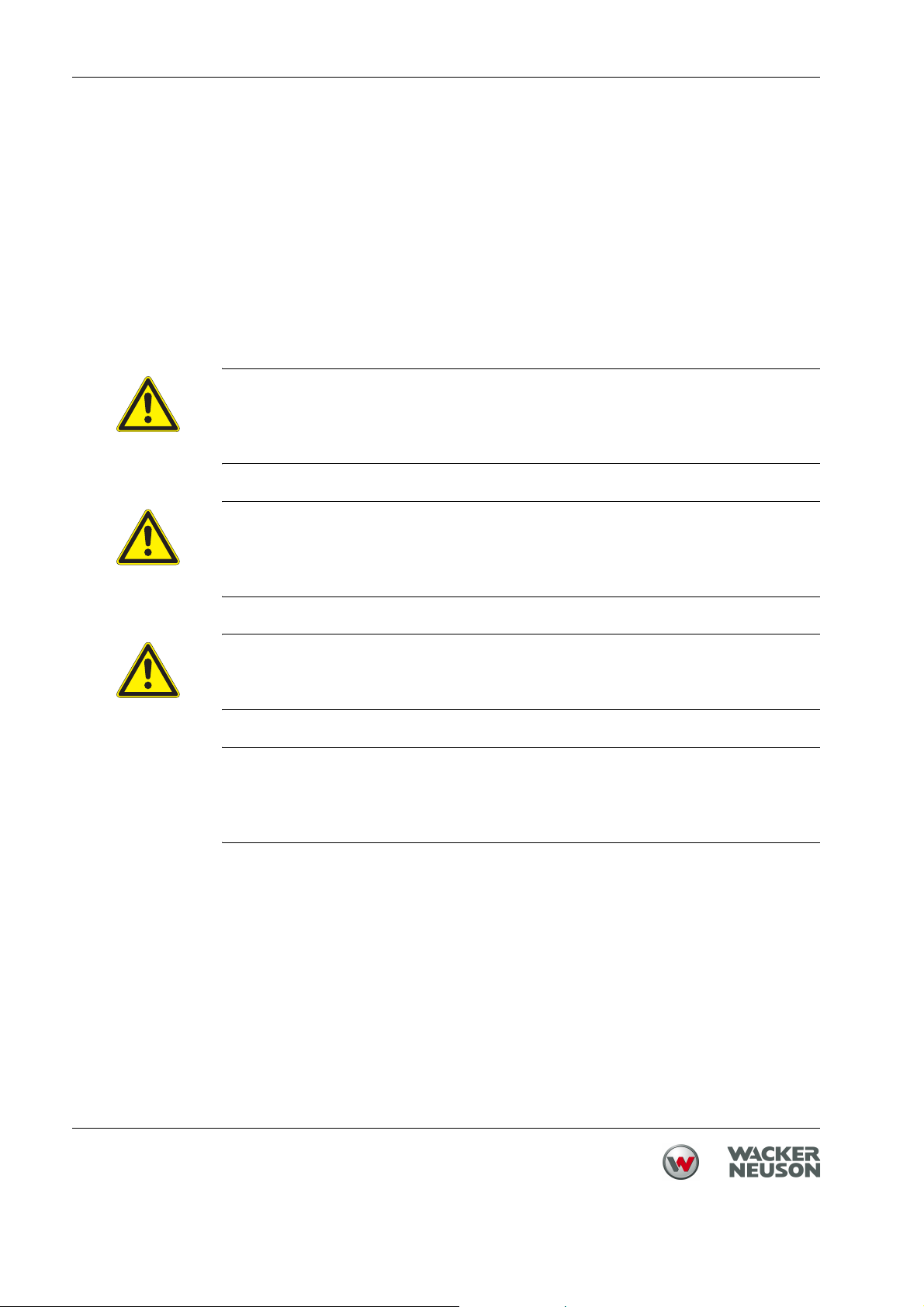
2.4 Identification of the machine
Nameplate data
The nameplate lists information that uniquely identifies your machine. This information is needed to order spare parts and when requesting additional technical
information.
f Enter the information of your machine into the following table:
Item Designation Your information
1 Group and type
2 Construction year
3 Machine no.
4 Version no.
5 Item no.
8
Page 9

3Safety
3.1 Principle
State of the art
Proper use
3 Safety
This machine has been constructed with state-of-the-art technology according to
the recognized rules of safety. Nevertheless, when used improperly, dangers to
the life and limb of the operator or to third persons or damage to the machine or
other materials cannot be excluded.
The machine must only be used for the following purposes:
Compaction of soils.
Compaction of asphalt.
Shaking in of paving stones.
The machine may not be used for the following purposes:
Compaction of intensely cohesive soils.
Compaction of frozen soils.
Compaction of hard, non-compactable soils.
Compaction of soils that are not capable of bearing a load.
Its proper use also includes the observance of all instructions contained in this
operator's manual as well as complying with the required service and maintenance instructions.
Any other use is regarded as improper. Any damage resulting from improper use
will void the warranty and the liability on behalf of the manufacturer. The operator
assumes full responsibility.
Structural modifications
Never attempt to modify the machine without the written permission of the manufacturer. To do so will endanger your safety and the safety of other people! In
addition, this will void the warranty and the liability on behalf of the manufacturer.
Especially the following are cases of structural modifications:
Opening the machine and the permanent removal of components from
Wacker Neuson.
Installing new components which are not from Wacker Neuson and not equiv-
alent to the original parts in design and quality.
Installation of accessories which are not from Wacker Neuson.
It is no problem to install spare parts from Wacker Neuson.
It is no problem to install accessories that are available in the Wacker Neuson
product range of your machine. Please refer to the installation regulations in this
operator's manual.
9
Page 10

3 Safety
Requirements for operation
The ability to operate the machine safely requires:
Proper transport, storage and setup.
Careful operation.
Careful service and maintenance.
Operation
Operate the machine only as intended and only when in proper working condition.
Operate the machine in a safety-conscious manner with all safety devices attached and enabled. Do not modify or disable any safety devices.
Before starting operation, check that all control and safety devices are functioning properly.
Never operate the machine in a potentially explosive environment.
Supervision
Never leave the machine running unattended!
Maintenance
Regular maintenance work is required in order for the machine to operate properly and reliably over time. Failure to perform adequate maintenance reduces the
safety of the machine.
Strictly observe the prescribed maintenance intervals.
Do not use the machine if it requires maintenance or repairs.
Malfunctions
If you detect a malfunction, you must shut down and secure the machine immediately.
Eliminate the malfunctions that impair safety immediately!
Have damaged or defective components replaced immediately!
For further information, refer to chapter Troubleshooting.
Spare parts, accessories
Use only spare parts from Wacker Neuson or such that are equivalent to the original parts in design and quality.
Only use accessories from Wacker Neuson.
Non-compliance will exempt the manufacturer from all liability.
10
Page 11

Exclusion of liability
Wacker Neuson will refuse to accept liability for injuries to persons or for damage
to materials in the following cases:
Structural modifications.
Improper use.
Failure to comply with this operator's manual.
Improper handling.
Using of spare parts which are not from Wacker Neuson and not equivalent
to the original parts in design and quality.
Using of accessories which are not from Wacker Neuson.
Operator's manual
Always keep the operator's manual near the machine or near the worksite for
quick reference.
If you have misplaced the operator's manual or require an additional copy, contact your Wacker Neuson representative or download the operator's manual from
the Internet (www.wackerneuson.com).
3 Safety
Always hand over this operator's manual to other operators or to the future owner
of the machine.
Country-specific regulations
Observe the country-specific regulations, standards and guidelines in reference
to accident prevention and environmental safety, for example those pertaining to
hazardous materials and wearing protective gear.
Complement the operator's manual with additional instructions taking into account the operational, regulatory, national or generally applicable safety guidelines.
Operator's controls
Always keep the operator's controls of the machine dry, clean and free of oil or
grease.
Operating elements such as ON/OFF switch, gas handles etc. may not be
locked, manipulated or changed without authorization.
Cleaning
Always keep the machine clean and be sure to clean it each time you have finished using it.
Do not use gasoline or solvents. Danger of explosion!
Do not use high pressure washers. Permeating water can damage the machine.
When electrical equipment is present, this can pose a serious injury risk from
electric shocks.
11
Page 12

3 Safety
Checking for signs of damage
Inspect the machine when it is switched off for any signs of damage at least once
per work shift.
Do not operate the machine if there is visible damage or defects.
Have any damage or defects eliminated immediately.
3.2 Qualification of the operating personnel
Operator qualifications
Only trained personnel are permitted to start and operate the machine. The following rules also apply:
You are at least 18 years of age.
You are physically and mentally fit.
You have received instruction on how to independently operate the machine.
You have received instruction in the proper use of the machine.
You are familiar with required safety devices.
You are authorized to start machines and systems in accordance with the
standards governing safety.
Your company or the operator has assigned you to work independently with
this machine.
Incorrect operation
Incorrect operation or misuse by untrained personnel can endanger the health
and safety of the operator or third persons and also cause machine and material
damage.
Operating company responsibilities
The operating company must make the operator's manual available to the operator and ensure that the operator has read and understood it.
Work recommendations
Please observe the recommendations below:
Work only if you are in a good physical condition.
Work attentively, particularly as you finish.
Do not operate the machine when you are tired.
Carry out all work calmly, circumspectly and carefully.
Never operate the machine under the influence of alcohol, drugs or medica-
tion. This can impair your vision, reactions and your judgment.
Work in a manner that does not endanger others.
Ensure that no persons or animals are within the danger zone.
12
Page 13

3.3 Protective gear
Work clothing
Clothing should be appropriate, i.e. should be close-fitting but not restrict your
movement.
When on construction sites, do not wear long hair loosely, loose clothing or jewelry including rings. These objects can easily get caught or be drawn in by moving machine parts.
Only wear clothing made of material that is not easily flammable.
Personal protective gear
Wear personal protective gear to avoid injuries or health hazards:
Non-skid, hard-toed shoes.
Work gloves made of durable material.
Overalls made of durable material.
Hard hat.
Ear protection.
3 Safety
Ear protection
3.4 Transport
Switching off the machine
Center pole in transport position
Observing hazardous materials regulations
This machine generates noise that exceeds the country-specific permissible
noise levels (individual rating level). It may therefore be necessary to wear ear
protection. You can find the exact value in the chapter Technical Data.
When wearing ear protection while working, you must pay attention and exercise
caution because your hearing is limited, e.g. in case someone screams or a signal tone sounds.
Wacker Neuson recommends that you always wear ear protection.
Before you transport the machine, it must be switched off, and the engine must
be given sufficient time to cool down.
Before commencing transport, move the center pole to the transport position. Let
the center pole latch into its lock.
Observe the national safety guidelines and the hazardous materials regulations
that apply to the respective means of transportation.
13
Page 14

3 Safety
Lifting
When lifting the machine, observe the following instructions:
Designate a skilled person to guide you for the lifting procedure.
You must be able to see or hear this person.
Use only suitable and certified hoisting gear, lifting tackle and load-bearing
equipment with sufficient lifting capacities.
Only use the attachment points described in the operator's manual.
Attach the machine securely to the hoisting gear.
Ensure that no one is nearby or under the machine.
Do not climb onto the machine.
Loading the machine
Loading ramps must be able to bear the load and be in a stable position.
Make sure that no one can be endangered if the machine slips away or tips over
or if machine parts suddenly move upward or downward.
Put the operating controls and moving parts in their transport position.
Secure the machine with load-securing straps so that it cannot tip over, fall down
or slide away. Only use the attachment points described in the operator's manual.
Transport vehicle
Use only suitable transport vehicles with sufficient load-carrying capacity and
suitable tie-down lugs.
Transporting the machine
Secure the machine on the transport device against tilting, falling or slipping.
Only use the lashing points listed in the operating instructions.
Also observe the country-specific regulations, standards and guidelines.
Restarting
Machines, machine parts, accessories or tools that were detached for transport
purposes must be re-mounted and fastened before restarting.
Only operate in accordance with the operating instructions.
3.5 Operating safety
Explosible environment
Never operate the machine in a potentially explosive environment.
14
Page 15

Work environment
Familiarize yourself with your work environment before you start work. This includes e.g. the following items:
Obstacles in the work and traffic area.
Load-bearing capacity of the ground.
The measures needed to cordon off the construction site from public traffic in
particular.
The measures needed to secure walls and ceilings.
Options available in the event of an accident.
Safety in the work area
When working with the machine especially pay attention to the following points:
Electric lines or pipes in work area.
Gas lines or water lines in the work area.
Starting the machine
3 Safety
Observe the safety information and warning notices located on the machine and
in the operator's manual.
Never attempt to start a machine that requires maintenance or repairs.
Start the machine as directed in the operator's manual.
Vertical stability
Always ensure that the machine is vertically stable and cannot tip over, roll or
slide away.
Proper operator position
Do not leave the proper operator position while operating the machine.
The proper operator position is behind the center pole of the machine.
Leaving the danger area
Injury may be caused by moving machines or flying materials.
Ensure that other persons observe a minimum safety distance of 2 m from the
machine.
Caution with movable parts
Keep your hands, feet and loose clothing away from moving or rotating machine
parts. Parts of your body being pulled in or crushed can cause serious injuries.
15
Page 16

3 Safety
Switching off the machine
Switch off the engine in the following situations:
Before breaks.
If you are not using the machine.
Store the machine in such a way that it cannot tilt, fall or slip.
Storage location
After operation, allow the machine to cool and then store it in a sealed-off, clean
and dry location protected against frost and inaccessible to children.
Not using starter sprays
Highly flammable starter sprays pose a fire hazard.
Do not use any starter sprays.
Starter sprays are highly flammable and can cause backfiring and engine damage.
Vibrations
When manually operated machines are intensively used, long-term damage
caused by vibrations cannot be precluded.
Observe the relevant legal instructions and guidelines to minimize vibration
stress.
Details on vibration stress associated with the machine can be found in the chapter Technical Data.
3.6 Safety during the operation of vibratory plates
Integrated driving mechanism
Machines with integrated driving mechanism must not be set down or stored on
the transport device. The driving mechanism is only intended for transport.
Belt guard
Never operate the machine without a belt guard!
Exposed belts and belt pulleys are dangerous and can cause serious injuries if
they pull in any part of your body or if parts are ejected.
Danger of falling over
Operate the machine so that it cannot tip over or fall down from bordered areas,
edges and steps.
16
Load-carrying capacity of the ground
Keep in mind that the load-carrying capacity of the earth to be compressed or
bed can be greatly reduced by the effects of vibration, for example near slopes.
Page 17

Avoiding crushing
When operating the machine, pay particular attention to avoid being squeezed
between the machine and an obstacle. Always look in the direction of travel!
Compacting on slopes
The following points must be observed if you plan to compact inclined surfaces
(slopes, escarpments):
Always stand above the machine on a slope.
Start at the bottom of a slope (slopes that can be easily managed in an up-
ward direction can be safely traveled in a downward direction also).
Never stand in a position where the machine could possibly fall. A slipping or
tipping machine can cause serious injuries.
Not exceeding the maximum tilt position
Do not exceed the maximum tilt position (see chapter Technical Data).
Only operate the machine at maximum tilt for short periods of time.
If you exceed the maximum tilt, the engine lubrication system will fail and thus
inevitably damage important engine parts.
3 Safety
Check the effects of vibration
Compacting work in the vicinity of buildings can lead to structural damage. For
this reason you must always check the possible effects of vibrations on surrounding buildings in the run-up to work.
You must take the following points into special consideration when evaluating the
effects of vibration:
Vibration behavior, sensitivity and resonance frequency of surrounding build-
ings.
Distance of the buildings from the vibrationsite (= worksite).
Condition of the soil.
You may need to carry out measurements to determine the vibration speed.
You must also comply with the relevant guidelines and regulations, particularly
DIN 4150-3.
The foundation must also have sufficient load-bearing capacity to withstand the
compaction energy. In case of doubt involve a soil mechanics specialist in the
evaluation.
Wacker Neuson is not liable for any structural damage.
17
Page 18

3 Safety
3.7 Safety during the operation of combustion engines
Checking for signs of damage
Check the engine while switched off for leaks and cracks in the fuel line, tank and
fuel cap at least once per work shift.
Do not operate the machine if there is visible damage or defects.
Have any damage or defects eliminated immediately.
Dangers during operation
Combustion engines can be dangerous, particularly during operation and when
refueling.
Read and follow all safety instructions. Otherwise there is a risk of personal injury
and/or damage to property!
Do not start the engine near spilt fuel or if you smell fuel – this may cause an explosion!
Remove the machine from such areas.
Remove the spilt fuel immediately!
Not changing the engine speed
Do not change the preset engine speed, as this may cause engine damage.
Preventing fires
Open flames and smoking are strictly prohibited in the immediate vicinity of the
machine.
Make sure that waste, such as paper, dry leaves or grass do not accumulate
around the exhaust muffler. The waste materials may ignite.
18
Page 19

Safety precautions when refueling
Please observe the following safety-relevant instructions when refueling:
Do not refuel near open flames.
Do not smoke.
Turn off the engine before refueling and allow it to cool down.
Refuel in a well-ventilated environment.
Wear fuel-proof protective gloves and, if there is the possibility of spraying,
protective goggles and clothing.
Do not inhale fuel vapors.
Avoid skin and eye contact with fuel.
For refueling, use clean tools such as a hopper.
Do not spill fuel, especially onto hot parts.
Remove any spilt fuel immediately.
Use the correct fuel grade.
Do not mix fuel with other liquids.
Fill the tank only up to the maximum marking. If there is no Maximum mark-
ing, do not fill up the tank completely.
Lock the fuel cap securely after refueling.
3 Safety
Operation in closed rooms
In closed or partially closed rooms such as tunnels, drifts or deep trenches, ensure sufficient ventilation and extraction by, for example, providing a powerful exhaust air fan.
Danger of poisoning! Do not inhale exhaust fumes. They contain toxic carbon
monoxide that can lead to unconsciousness or death.
Caution with hot parts
Do not touch any hot parts such as the engine block or exhaust muffler during
operation or directly afterwards. These parts can become very hot and cause severe burns.
Shutting off the fuel tap
When the machine stops, shut off the fuel tap.
Cleaning the engine
Clean the engine when it is cool to remove any dirt.
Do not use gasoline or solvents. Danger of explosion!
19
Page 20

3 Safety
3.8 Safety during the operation of hydraulic machines
Hydraulic oil
Hydraulic oil is harmful to health.
Wear safety glasses and safety gloves when handling hydraulic oil.
Avoid direct skin contact with hydraulic oil. Remove hydraulic oil from the skin immediately with soap and water.
Make sure that no hydraulic oil comes gets in the eyes or on the body. See a physician immediately if hydraulic oil gets into the eyes or is swallowed.
Do not eat and drink while handling hydraulic oil.
Make sure to have extreme cleanliness. Contamination of the hydraulic oil with
dirt or water can cause premature wear or failure of the machine.
Dispose of left over and spilled hydraulic oil according to the applicable regulations for environmental protection.
3.9 Maintenance
Maintenance work
Service and maintenance work must only be carried out to the extent described
in these operating instructions. All other procedures must be performed by your
Wacker Neuson representative.
For further information, refer to chapter Maintenance.
Switching off the engine
Before carrying out care or maintenance work, switch off the engine and allow it
to cool down.
For gasoline powered engines, you must pull off the spark plug cap.
Disconnecting the battery
For machines with electric starter, you must disconnect the battery before working on the electronic parts.
Using only a Wacker Neuson battery
Use only Wacker Neuson batteries to replace defective batteries, see chapter
Technical Data.
Only the Wacker Neuson battery is vibration resistant and thus suitable for the
high vibratory stresses.
20
Page 21

Working on the battery
Always take the following safety measures when working with the battery:
No fire, sparks, or smoking while working with batteries.
Batteries contain corrosive acid. Use acid-proof protective gloves and protec-
tive goggles when working with batteries.
Avoid short circuits due to improper connection or bypassing with tools.
Disconnect the negative terminal first when disconnecting the battery.
Connect the positive terminal first when connecting the battery.
Re-fasten terminal covers after connecting the battery.
Assembling safety devices
If it was necessary to dismantle safety devices, they must be reassembled and
checked immediately after completing maintenance work.
Always tighten loosened screw connections, complying with prescribed starting
torque.
Handling operating fluids safely
3 Safety
Observe the following points when handling operating fluids, e.g. fuels, oils,
greases, coolants etc.:
Always wear personal safety clothing.
Avoid skin and eye contact with operating fluids.
Do not inhale or swallow operating fluids.
In particular, avoid contact with hot operating fluids. Burn and scalding haz-
ard.
Dispose of replaced or spilled operating fluids according to the applicable
regulations for environmental protection.
If operating fluids escape from the machine, cease operation of the machine
and have it repaired immediately by your Wacker Neuson representative.
21
Page 22
3 Safety
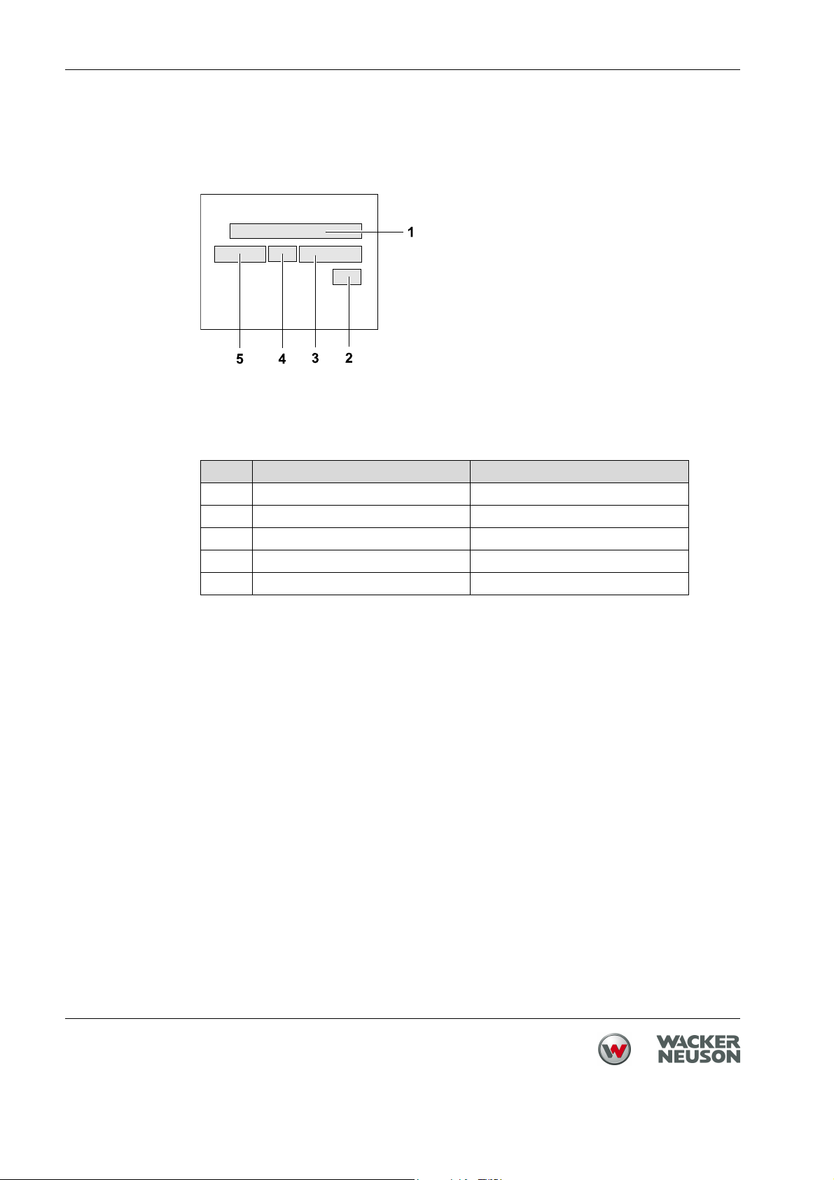
3.10 Safety and information labels
Your machine has adhesive labels containing the most important instructions
and safety information.
Make sure that all the labels are kept legible.
Replace any missing or illegible labels.
The item numbers for the labels are in the parts book.
Pos. Label Description
1 If the machine falls, it can cause severe
crushing injuries.
0219260
f Only lift the machine with certified
hoist and lifting tackle (safety load
hook).
f Do not lift the machine with the exca-
vator shovel by the central suspension.
2 Start-Stop.
0219259
3 Guaranteed sound power level.
22
Page 23

Pos. Label Description
WARNING
WARNUNG
ADVERTENCIA
ADVERTISSEMENT
0219176
CAUTION
VORSICHT
ATENCIÓN
ATTENTION
0219262
4 Improper handling can cause serious
damage to the engine.
f When using the integrated wheels,
always turn off the engine.
If the engine is running, engine lubrication cannot be ensured in the transport
position. There is also a danger that oil
may leak out of the engine crankcase
breather.
5 If the machine falls, it can cause severe
crushing injuries.
0
2
0
2
0
0
0
6 Wear personal protective gear to avoid
0219175
f Do not lift the machine by the guide
handle or the center pole.
injuries or health hazards:
Ear protection.
Read the operator's manual before startup.
3 Safety
7 US machines Warning.
0219261
8 US machines Caution.
23
Page 24

4 Scope of delivery
4 Scope of delivery
Item Designation Item Designation
1 Machine 3 Parts book
2 Operator's manual
The machine is delivered fully assembled and after unpacking it is ready for operation.
The scope of delivery includes:
Machine.
Operator's manual.
Parts book.
24
Page 25

5 Structure and function
5.1 Application
Use the machine only as intended, see chapter Safety, Proper use.
5.2 Functional description
5 Structure and function
Item Designation Item Designation
1 Air cleaner 8 Exciter V-belt
2 Throttle lever 9 Exciter
3 Control handle 10 Base plate
4 Guide handle head 11 Battery
5 Upper mass 12 Starter
6 Vibration dampers 13 Drive motor
7 Centrifugal clutch
The vibration required for compaction is generated by the exciter (9) that is permanently attached to the base plate (10). The exciter (8) is designed as a central
vibrator with directional vibrations.
This principle allows you to change the direction of vibration by simply turning the
eccentric weights (9). This makes a gradual transition possible between the vibration states: moving forward, moving in reverse and in a stationary position.
25
Page 26

5 Structure and function
This procedure is hydraulically controlled with the control handle (3) on the guide
handle head (4).
The drive motor (13) attached to the upper mass (5) powers the exciter (9). The
torque is transferred non-positively by the centrifugal clutch (7) and the exciter
V-belt (8).
When the motor speed is low, the centrifugal clutch (7) interrupts the power flow
to the exciter (9) which allows the drive motor (13) to idle properly. The speed of
the drive motor (13) can be varied at the throttle lever (2).
The upper mass (5) and the base plate (10) are connected to each other via
4 vibration-damping vibration dampers (6). This damping prevents very high frequencies from being transferred to the upper mass (5). This maintains proper
functioning of the drive motor (13) despite a high compaction capacity.
Depending on machine type, the drive motor may also include an electronic starter in addition to the recoil starter.
The combustion air is aspirated via an air cleaner. The condition of the air cleaner can be checked using the air cleaner maintenance indicator.
26
Page 27

6 Components and operator's controls
Machine
6 Components and operator's controls
Item Designation Item Designation
1 Central suspension 6 Integrated driving mechanism
2 Fuel tank 7 Guide handle
3 Battery 8 Control handle
4 Recoil starter 9 Throttle lever
5 Electronic starter
27
Page 28

6 Components and operator's controls
Electronic starter (only certain machine types)
Item Designation Item Designation
1 Operation control lamp 3 Oil pressure control lamp
2 Charging control lamp 4 Ignition lock
28
Page 29

7 Transport
7 Transport
WARNING
Improper handling can result in injury or serious material damage.
f Read and follow all safety instructions of this operator's manual, see chapter
Safety.
WARNING
Danger due to the machine falling.
If the machine falls, it can cause severe injury such as crushing.
f Only use suitable and tested hoisting gear and lifting tackle (safety load
hooks) of sufficient lifting capacity.
f Only lift the machine by the central suspension.
f Attach the machine firmly to the hoisting gear.
f Do not lift the machine with the excavator shovel or the forklift by the central
suspension.
f Do not lift the machine by the handle.
f Leave the danger area while lifting.
DANGER
Danger of fire and explosions by fuel.
Any fuel that escapes can ignite and cause severe burns.
f Lift and move the machine in the upright position.
29
Page 30

7 Transport
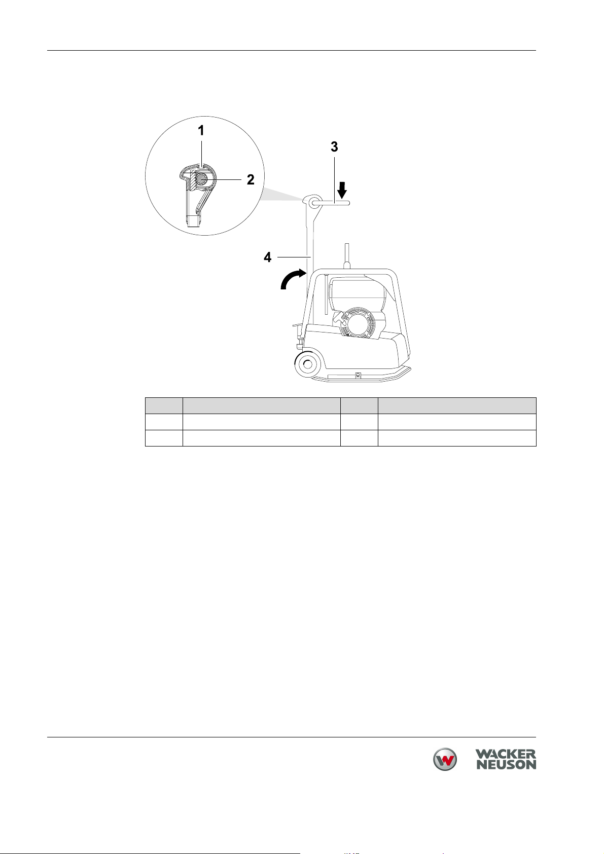
7.1 Transporting the machine
Item Designation Item Designation
1 Guide handle 3 Tie-down lugs (protective frame)
2 Central suspension (attachment
point)
1. Place the machine upright on a flat surface.
2. Switch off the engine.
3. Vertically set guide handle head and lock into place.
4. Fasten suitable lifting tackle to the central suspension (2) provided.
5. Lift the machine evenly with the hoist.
6. Carefully set the machine down on a suitable transport vehicle.
7. If you transport the vibrating plate compactor on the cargo area of a vehicle,
strap it down securely at the protective frame (3).
NOTICE
If the engine is running, engine lubrication cannot be ensured in the transport
position. This can cause serious engine damage.
There is also a danger that oil may leak out of the engine crankcase breather.
f When using the integrated driving mechanism, you must turn off the engine.
30
Page 31

8 Use and operation
WARNING
Improper handling can result in injury or serious material damage.
f Read and follow all safety instructions of this operator's manual, see chapter
Safety.
8.1 Prior to starting the machine
8.1.1 Checks before startup
Before you start the engine, check the following:
Fuel level.
Motor oil level.
Air cleaner.
Water separator
Fuel lines for leaks.
External screw connections for tightness.
8 Use and operation
31
Page 32

8 Use and operation
8.2 Starting up
8.2.1 Starting the engine with recoil starter
Item Designation
1 Throttle lever
2 Recoil starter
Note: Do not start the engine until you are sure that it is vertically stable.
1. Set throttle lever to position 1.
2. Slowly pull out the recoil starter until you feel compression.
3. Let the cable rewind from this compression point.
4. Start now by gradually accelerating the engine via the cable (not in a jerking
manner as with gasoline engines). Use the entire length of the cable.
32
Page 33
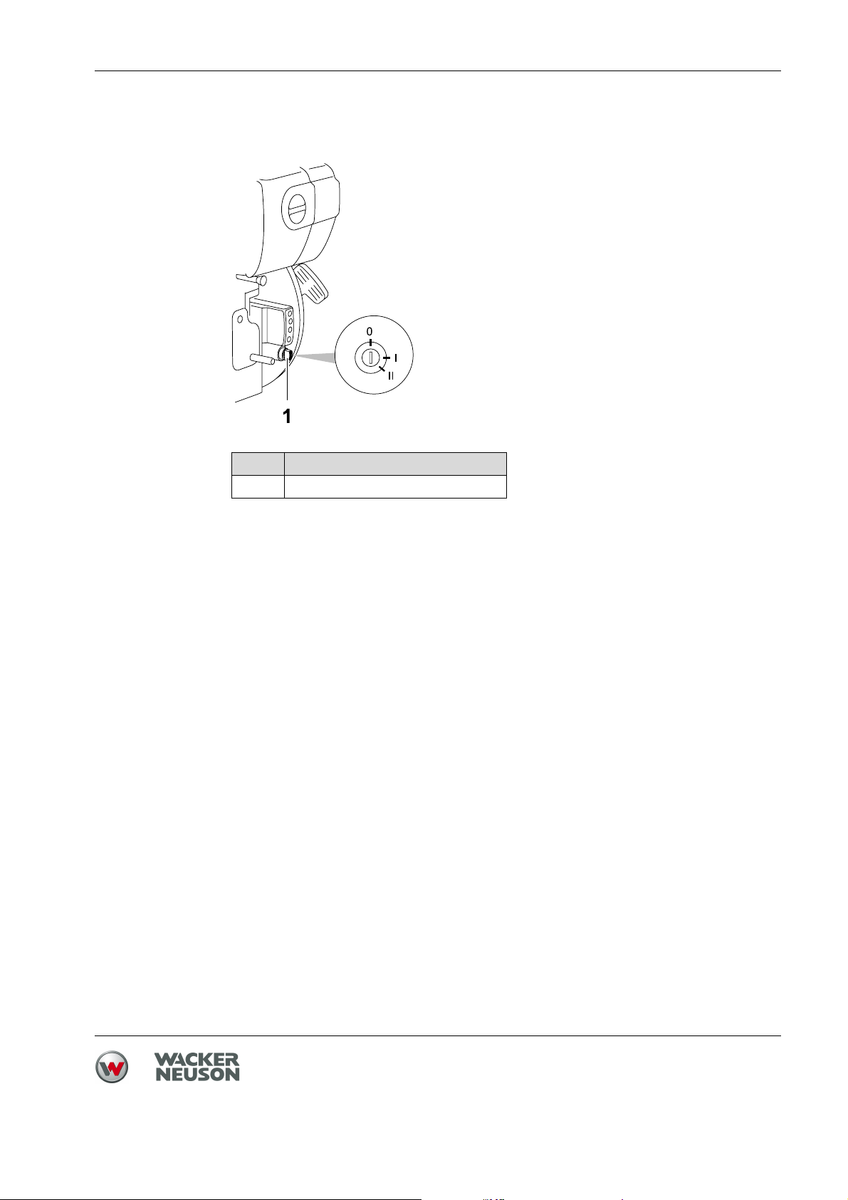
8.2.2 Starting the engine with electronic starter
Item Designation
1 Ignition lock
8 Use and operation
1. Set throttle lever to position 1.
2. Insert the key into the ignition lock.
3. Turn key to position II and release when the engine has started.
Note: Abort the start attempt after no more than 15 seconds.
Note: Do not turn the key to position 0 or remove the key while the engine is
running, as this will stop the battery charging.
33
Page 34

8 Use and operation
8.3 Operating the machine
8.3.1 Operating in the forward and reverse direction
f Press the control handle in the direction of travel.
Note: The forward and reverse speed can be continuously varied.
8.3.2 Compacting on a slope
Compacting on slopes
The following points must be observed if you plan to compact inclined surfaces
(slopes, escarpments):
Always stand above the machine on a slope.
Start at the bottom of a slope (slopes that can be easily managed in an up-
ward direction can be safely traveled in a downward direction also).
Never stand in a position where the machine could possibly fall.
Not exceeding the maximum tilt position
Do not exceed the maximum tilt position (see chapter Technical Data).
Only operate the machine at maximum tilt for short periods of time.
If you exceed the maximum tilt, the engine lubrication system will fail and thus
inevitably damage important engine parts.
34
Page 35

8.4 Decomissioning
8 Use and operation
Item Designation
1 Off switch
2 Ignition lock
Turning off the engine
1. Set throttle lever to position 0.
2. Press the OFF switch.
Only for machine types with electronic starter:
3. Turn key to position 0.
4. Remove key if necessary.
Note: To prevent battery discharge, always remove the key or turn it to posi-
tion 0.
35
Page 36

9 Maintenance
9 Maintenance
WARNING
Improper handling can result in injury or serious material damage.
f Read and follow all safety instructions of this operator's manual, see chapter
WARNING
Injury may be caused by uncontrolled startup and moving parts.
f Carry out maintenance work only when the engine is off.
WARNING
Danger of poisoning by exhaust fumes.
Exhaust fumes contain toxic carbon monoxide that can lead to unconsciousness or death.
f Carry out maintenance work only when the engine is off.
Safety.
36
Page 37

9.1 Maintenance schedule
9.1.1 One-time maintenance after initial operation
Note: The following maintenance tasks need only be performed after initial
operation at this interval.
Maintenance work After the
first
25 hours
9 Maintenance
Change engine oil.
Check the valve clearance,
set to 0.10 mm when the engine is cold. *
* Have these tasks carried out by the service
department of your Wacker Neuson contact person.
9.1.2 Daily maintenance work
Maintenance work Daily before
Check the intake area of the
combustion air and cooling
air.
Check engine oil level.
Check water separator.
Check fuel tank:
- Fuel level.
- Leaks.
- Lines for leaks.
- Check the tank seal for
leaks – change, if necessary.
operation
Daily after
operation
Check the air cleaner maintenance indicator while the engine is running.
Clean or replace the filter element as needed.
Check that Bowden cable
moves freely.
Clean the machine.
37
Page 38

9 Maintenance
9.1.3 Regular maintenance
Maintenance work Monthly Every
150 hours
Check exciter oil - fill if necessary.
Check hydraulic oil - fill if necessary.
Check the V-belt tension - tighten as needed.
Check that the fastening
screws are tight:
Protective frame.
Central suspension.
Check exciter oil - fill if necessary.
Change engine oil.
Change exciter oil. *
Check that the fastening
screws are tight:
Drive motor. *
Every
250 hours
Every
500 hours
Every
1000 hours
Check the valve clearance, set
to 0.10 mm when the engine is
cold. *
Replace the fuel filter. *
Replace air cleaner.
Clean oil filter. *
* Have these tasks carried out by the service department of your Wacker Neuson contact person.
38
Page 39

9.2 Maintenance work
9.2.1 Cleaning machine
WARNING
Use of improper cleaning agents may lead to fire or explosion.
f Do not use gasoline or any other solvents to clean components.
f Clean the machine with water after each use.
High pressure washers or chemical agents must not be used.
9.2.2 Check the air cleaner maintenance indicator
9 Maintenance
f Rev the engine briefly to its maximum speed. If the rubber bellows contract
and cover the green field "2" in the process, the air cleaner system must be
serviced. If you are working in dusty conditions, check the rubber bellows
several times a day.
39
Page 40

9 Maintenance
9.2.3 Cleaning the air cleaner
Note: If the motor starts smoking and if the motor output drops at the same
1. Place the machine upright on a flat surface.
time, this indicates that the filter is clogged.
2. Switch off the engine.
3. Remove and clean cartridge. Tap lightly against the cartridge so that dust
falls out of the paper element.
4. Do not used compressed air. Clean instead by hand with a clean cloth! Ensure that you do not wipe any dirt from the housing into the engine intake.
40
Page 41

9.2.4 Checking the water separator
Item Designation
1 Inspection glass
2Drain plug
9 Maintenance
1. Place the machine upright on a flat surface.
2. Switch off the engine.
3. Check whether there is water in the inspection glass of the water separator.
4. If necessary, unscrew drain plug and catch water in a collecting container.
If fuel comes out rather than water, re-tighten the drain plug.
Note: Dispose of the water in accordance with the applicable environmental
regulations.
41
Page 42

9 Maintenance
9.2.5 Checking engine oil level
Item Designation
1 Oil level dipstick
2Mark
1. Place the machine upright on a flat surface.
2. Switch off the engine.
3. Remove any dirt around the oil level dipstick.
4. Remove the oil level dipstick and wipe it with a clean, lint-free cloth.
5. Screw the oil level dipstick all the way back in and pull it out again.
6. Check: The motor oil level must be between the lower and upper marks.
7. If necessary, pour new engine oil into the opening until the upper mark is
reached on the oil level dipstick (see chapter Technical data for oil type).
8. Screw in the oil level dipstick and tighten it by hand.
42
Page 43

9.2.6 Changing the engine oil
9 Maintenance
Item Designation Item Designation
1 Oil level dipstick 3 Oil drain hose
2 Oil change valve
Note: The work area should be covered with a waterproof sheet to protect
the floor (protection of the environment).
Note: Drain the oil while the engine is still hot. This ensures that the oil will
be drained quickly and completely.
1. Place the machine upright on a flat surface.
2. Bring the engine to a hand warm temperature, either by letting it cool down
or running it until it is warm.
3. Switch off the engine.
4. Unscrew and remove the oil level dipstick.
5. Screw the oil drain hose onto the oil change valve.
Collect the oil with a suitable container and dispose of properly.
6. Top up oil via the filler neck and check oil level.
See the chapter Technical data for oil quantity and oil specification.
7. Unscrew oil drain hose and screw on oil change valve.
8. Screw in the oil level dipstick and tighten it by hand.
Note: Dispose of the used oil in accordance with the applicable regulations.
43
Page 44
9 Maintenance
9.2.7 Checking / filling hydraulic oil level
Item Designation Item Designation
1 Filler hole 3 Control handle
2 Gear 4 Guide handle
1. Place the machine upright on a flat surface.
2. Switch off the engine.
3. Let machine cool off.
4. Vertically set guide handle head and lock into place.
5. Press the control handle in the advance travel position.
6. Remove any dirt around the filler hole.
7. Check: Oil level must reach upper edge of the gear.
8. Open filler hole.
9. If necessary, add new hydraulic oil through the filler hole up to the upper edge
of the gear wheel.
See the chapter Technical data for the oil specification.
10. Close the filler hole and tighten.
Note: The hydraulic control is self-bleeding.
44
Page 45

9.2.8 Checking exciter oil level
9 Maintenance
Item Designation
1 Filler hole
2 Start of thread
1. Place the machine upright on a flat surface.
2. Switch off the engine.
3. Let machine cool off.
4. Remove any dirt around the filler hole.
WARNING
Hot exciter oil can spill, causing scalding injuries.
f Do not open the screw plug on the exiter while the exciter oil is hot.
f Let machine cool off.
5. Open filler hole.
6. Check: Oil level must reach the start of the thread of the filler hole.
7. If necessary, fill exciter oil through the filler hole.
45
Page 46

9 Maintenance
8. Close filler hole and use a torque wrench to tighten it to 100 Nm.
46
Page 47

9.2.9 Re-tighten exciter V-belt
9 Maintenance
Item Designation Item Designation
1 V-belt 5 Screws (3 pieces)
2 Engine V-belt disc 6 Belt guard
3 Disc 7 Screws (3 pieces)
4
V-belt pulley half
1. Place the machine upright on a flat surface.
2. Switch off the engine.
3. Let machine cool off.
4. Remove V-belt protector.
5. Unscrew screws at the engine V-belt disc and remove external V-belt pulley
half.
6. Remove the necessary number of washers (normally the removal of one disc
suffices).
7. Mount the removed washers on the outside of the V-belt pulley half.
8. Attach V-belt pulley half and tighten with 3 screws to 10 Nm.
Note: Turn the V-belt pulley half in the process to avoid pinching the V-belt.
9. Remount V-belt protector. Tighten screws with a torque wrench to 10 Nm.
10. Let the machine run for a short while.
47
Page 48

9 Maintenance
11. If necessary retighten the screws.
48
Page 49

10 Malfunctions
Please refer to the following table if the machine does not work properly. It contains potential faults, their causes and remedies.
Notify your Wacker Neuson contact in case of malfunctions you cannot or may
not remedy yourself.
Malfunction Cause Remedy
10 Malfunctions
Reverse travel speed too low. Insufficient hydraulic oil in the
guide handle head.
Advance travel speed too low. Too much hydraulic oil in the
guide handle head.
No advance travel. Mechanical malfunction. Have the machine repaired. *
Loss of hydraulic oil. Leaks, hydraulic hose is defec-
tive.
Engine will not start. Throttle lever in position 0. Set throttle lever to position 1.
No fuel at the injection pump. Fill the tank with fuel. Check the
Valve clearance is incorrectly
set.
Valves are worn. Have the machine repaired. *
Cylinder and/or piston ring
wear.
Injector is not functioning properly.
Add hydraulic oil.
Adjust oil level according to the
fill level mark.
Have the machine repaired. *
entire fuel system.
Check the supply line to the engine and fuel filter. *
Check the valve clearance and
adjust as needed. *
No vibration while engine is running.
Charging control lamp does not
go out.
Oil control lamp does not go
out.
* Have these tasks carried out by the service department of your Wacker Neuson contact person.
V-belt is worn out. Replace V-belt.
Clutch linings are worn out. Replace the clutch linings. *
Generator defective. Have the machine repaired. *
Controller defective.
Motor oil level is too low. Top up with engine oil.
49
Page 50

10 Malfunctions
10.1 Boost
WARNING
Danger of explosion due to detonating gas.
Injury may result from spraying acid.
f Wear safety glasses and acid-proof protective gloves.
f The donor battery and the machine's battery must have the same voltage
(12 V).
f Avoid short circuit due to voltage reversal (positive to positive, negative to
negative).
f Follow the booster cable connection sequence.
Note: Use only insulated booster cables with a cross section of at least
16 mm².
50
The following connection sequence must be used when starting with an external
battery:
1. Clamp red booster cable to positive pole (1) of the discharged battery using
a pair of clamping pliers.
2. Clamp the other pair of clamping pliers of the red booster cable to the donor
battery's positive pole (2).
3. Clamp black booster cable to negative pole (3) of the donor battery using a
pair of clamping pliers.
4. Attach the other clamping pliers of the black booster cable to the ground connector (4) of the equipment, e.g. the engine support.
5. Start the engine and allow it to warm up (max. 15 seconds).
Page 51

10 Malfunctions
6. Follow these steps in reverse to remove all clamped on cables - first the black
and then the red booster cable.
51
Page 52

11 Disposal
11 Disposal
11.1 Disposal of batteries
For customers in EU countries
This device contains one or more batteries or rechargeable batteries (hereafter
referred to as "batteries"). This battery is subject to the European Directive
2006/66/EC on (waste) batteries, as well as the corresponding national legislation. The battery directive outlines the procedure for handling batteries across
the EU.
the end user, only dispose of waste batteries via the manufacturer, the dealer or
special collection points for this purpose (legal obligation to return), which is free
of charge. Dealers and manufacturers are obliged to accept the return of the batteries and to use them properly or to dispose of them as hazardous waste (legal
obligation to accept). You can also return any used batteries you obtained from
us free of charge. If you do not return the batteries to one of our branches personally, make sure you have paid sufficient postage for its return. Please also
note any information in the sales contract and the general terms and conditions
from the point of sales.
The proper disposal of the battery prevents the occurrence of any negative effects on people or the environment, follows the specific procedures for handling
harmful substances and enables valuable raw materials to be recycled.
The battery is labelled with the symbol of a crossed out dustbin
shown here. Below this symbol is a list of all the harmful substances
it contains, namely "Pb" for lead, "Cd" for cadmium and "Hg" for
mercury.
Batteries may not be disposed of with normal household waste. As
52
For customers in non-EU countries
This device contains one or more batteries or rechargeable batteries (hereafter
referred to as "batteries"). The proper disposal of the battery prevents the occurrence of any negative effects on people or the environment, follows the specific
procedures for handling harmful substances and enables valuable raw materials
to be recycled. Therefore, we recommend that this battery is disposed of in a
separate, environmentally-friendly waste collection and not with normal household waste. In some cases, national legislation stipulates the separate disposal
of batteries. Please ensure you dispose of this battery in accordance with the valid regulations in your country.
Page 53

12 Accessories
There is a wide range of accessories available for the machine.
For more information on the individual accessories, visit the following website:
www.wackerneuson.com.
12 Accessories
53
Page 54

13 Technical data
13 Technical data
Machine
Designation Unit DPU 2540H DPU 2550H DPU 2560H DPU 2560Hts
Item no. 0610035 0610036 0610037 0610038
Length x width x height
(guide handle in transport
position)
mm (ft) 733 x 400 x
1,170
(2.4 x 1.3 x
733 x 500 x
1,170 (2.4 x
1.6 x 3.8)
3.8)
Operating weight kg (lb) 160
(353)
Advance and reverse
travel
Area capacity m²/h
m/min
(ft/min)
(ft²/h)
21
(68.9)
504
(5425)
166
(366)
20
(65.6)
600
(6458)
Maximum permissible tilt ° 25
Sound pressure level L
dB(A) 94
pA
at operator's station
Total vibration value of the
acceleration a
hv
*
Uncertainty of measure-
m/s
m/s
2
2
3.1 3.2
1.0
ment of the vibration total
value of the acceleration
ahv
733 x 600 x 1,170
(2.4 x 1.9 x 3.8)
171
(377)
19
(62.3)
684
(7362)
23
(75.5)
828
(8913)
* Determined according to DIN EN ISO 5349.
54
Page 55

13 Technical data
Designation Unit DPU 3050H DPU 3050He DPU 3060H DPU 3060Hts
Item no. 0610039,
0610298 0610040 0610042
5100000310
Length x width x height
(guide handle in transport
mm (ft) 733 x 500 x 1,170
(2.4 x 1.6 x 3.8)
733 x 600 x 1,170
(2.4 x 1.9 x 3.8)
position)
Operating weight kg (lb) 181 (399) 206 (454) 190 (419)
Advance and reverse
travel
Area capacity m²/h
m/min
(ft/min)
(ft²/h)
21
(65.6)
630
(6781)
19
(62.3)
684
(7362)
Maximum permissible tilt ° 25
Sound pressure level L
dB(A) 95
pA
at operator's station
Total vibration value of the
acceleration a
hv
*
Uncertainty of measure-
m/s
m/s
2
2
3,6 3,2 3,3
1.0
ment of the vibration total
value of the acceleration
ahv
23
(75.5)
828
(8913)
* Determined according to DIN EN ISO 5349.
55
Page 56

13 Technical data
Designation Unit DPU 3060Hets DPU 3070H
Item no. 0610302 0610041
Length x width x height
(guide handle in transport
mm
(ft)
733 x 600 x 1,170
(2.4 x 1.9 x 3.8)
733 x 700 x 1,170
(2.4 x 2.3 x 38)
position)
Operating weight kg (lb) 215 (474) 195 (430)
Advance and reverse
travel
Area capacity m²/h
m/min
(ft/min)
(ft²/h)
23
(75.5)
828
(8913)
18
(59.1)
756
(8138)
Maximum permissible tilt ° 25
Sound pressure level L
dB(A) 95
pA
at operator's station
Total vibration value of the
acceleration a
hv
*
Uncertainty of measure-
m/s
m/s
2
2
3.2 3.2
1.0
ment of the vibration total
value of the acceleration
ahv
* Determined according to DIN EN ISO 5349.
56
Page 57

13 Technical data
Designation Unit DPU
3750Hts
Item no. 0610321,
DPU
3750Hets
DPU
3760Hts
DPU
3760Hets
0610322 0610358 0610359
5100000311
Length x width x height
(guide handle in transport
mm (ft) 733 x 500 x 1,170
(2.4 x 1.6 x 3.8)
733 x 600 x 1,170
(2.4 x 1.9 x 3.8)
position)
Operating weight kg (lb) 247 (544) 265 (584) 256 (564) 274 (604)
Advance and reverse
travel
Area capacity m²/h
m/min
(ft/min)
(ft²/h)
27
(88.5)
810
(8719)
26
(85.3)
936
(10075)
Maximum permissible tilt ° 25
Sound pressure level L
dB(A) 95
pA
at operator's station
Total vibration value of the
acceleration a
hv
*
Uncertainty of measure-
m/s
m/s
2
2
2,4
1.0
ment of the vibration total
value of the acceleration
ahv
* Determined according to DIN EN ISO 5349.
57
Page 58

13 Technical data
Drive motor
Designation Unit DPU 25.. DPU 30.. DPU 37..
Manufacturer HATZ
Type 1B20 1B30
Engine displacement cm³ (in³) 243 (14.8) 347 (21.2)
Rated output*
Operating power kW 1.5 1.9 1,7
Operating blade speed rpm 2,800
Fuel type
Fuel consumption l/h (qt/h) 0.4 (0,42) 0.6 (0.63)
Tank capacity l (qt) 3.0 (3.17) 5.0 (5.28)
Oil specification
Oil quantity
* Equivalent to the installed power output in accordance with the directive 2000/14/EC.
kW 3.1 4.2
Diesel according to DIN EN 590
Fuchs Titan Unic 10W40 MC
(SAE 10W40)
l (qt) 0.9 (0,95) 1.1 (1.16)
Exciter
Designation Unit DPU 25.. DPU 30.. DPU 37..
Vibrations rpm (Hz) 5,400 (90)
Centrifugal force kN 25 30 37
58
Oil specification Fuchs Titan Unic 10W40 MC
Oil quantity l (qt) 0.6 (0.63)
Hydraulic
Designation Unit DPU 25.. DPU 30.. DPU 37..
Oil specification
Oil quantity
(SAE 10W40)
Fuchs Renolin MR 520
l (qt) 0,4 (0.42)
Page 59

Electrical
Designation Unit DPU 3050He, DPU 3060Hets,
Battery type Special Wacker Neuson battery for
13 Technical data
DPU 3750Hets, DPU 3760Hets
vibration plates, 12 V - 18 Ah,
maintenance free
59
Page 60

13 Technical data
60
Page 61

EC Declaration of Conformity
Manufacturer
Wacker Neuson Produktion GmbH & Co. KG, Preußenstraße 41, 80809 München
Product
Product
Product category Vibrating plate
Product function Compacting soils
Item number 0610035, 0610036,
Net installed power 3,4 kW 3,4 kW 3,4 kW
Measured sound power
level
Guaranteed sound power
level
DPU 25.. DPU 30.. DPU 37..
0610039, 0610298,
0610037, 0610038
104 dB(A) 104 dB(A) 104 dB(A)
108 dB(A) 108 dB(A) 108 dB(A)
0610040, 0610041,
0610302, 0610042
0610321, 0610322,
0610358, 0610359
Conformity assessment procedure
According to 2000/14/EC, Appendix VIII, 2005/88/EC.
Notified body
VDE Prüf- und Zertifizierungsinstitut GmbH, Merianstraße 28, 63069 Offenbach/Main
Guidelines and standards
We hereby declare that this product meets and complies with the relevant regulations and
requirements of the following guidelines and standards:
2006/42/EG, 2000/14/EG, 2005/88/EG
Authorized person for technical documents
Axel Häret,
Wacker Neuson Produktion GmbH & Co. KG, Preußenstraße 41, 80809 München
München, 01.08.2011
Dr. Michael Fischer
Director of Technology and Innovation
Translation of the original Declaration of Conformity
Page 62

Page 63

Page 64

Wacker Neuson Produktion GmbH & Co. KG, Preußenstraße 41, D-80809 München, Tel.: +49-(0)89-3 54 02-0 Fax: +49 - (0)89-3 54 02-390
Wacker Neuson Limited - Room 1701–03 & 1717–20, 17/F. Tower 1, Grand Century Place, 193 Prince Edward Road West, Mongkok, Kowloon, Hongkong.
Wacker Neuson Production Americas LLC, N92W15000 Anthony Ave., Menomonee Falls, WI 53051
Tel. : (262) 255-0500 Fax: (262) 255-0550 Tel.: (800) 770-0957
Tel: (852) 3605 5360, Fax: (852) 2758 0032
 Loading...