

Page 1

Operator’s manual
Vibratory plate
Test machine
DPU
Model DPU
Document 5100008833
Issue May 2015
Version 01
Language en
Page 2

Manufacturer
Wacker Neuson Produktion GmbH & Co. KG
Preussenstrasse 41
80809 Munich
www.wackerneuson.com
Tel.: +49-(0)89-354 02-0
Fax: +49-(0)89-354 02-390
Translation of the original operator’s manual in German
100_0000_0001.fm 2
Page 3

Inhalt
Table of contents
1 Preface ...................................................................................................................................5
2 Introduction ...........................................................................................................................6
2.1 Using the manual......................................................................................................................... 6
2.2 Storage location of the manual.................................................................................................... 6
2.3 Accident prevention regulations................................................................................................... 6
2.4 More information.................................................................................................................. ........ 6
2.5 Target group................................................................................................................................ 6
2.6 Explanation of symbols................................................................................................................ 6
2.7 Wacker Neuson Contact person.................................................................................................. 7
2.8 Disclaimer.................................................................................................................................... 7
2.9 Product identification of the machine........................................................................................... 7
3 Security ..................................................................................................................................8
3.1 Policy........................................................................................................................................... 8
3.2 Areas of responsibility of the operator ......................................................................................... 8
3.3 User responsibilities..................................................................................................................... 9
3.4 Personnel qualification..................... .... ... ... ... ... .... ... ... ... ............................................................... 9
3.5 General hazards.......................................................................................................................... 9
3.6 General Safety Instructions ......................................................................................................... 9
3.7 Specific safety instructions – Vibratory plates ........................................................................... 10
3.8 Specific safety instructions – remote controlled vibratory plates ............................................... 10
3.9 General safety instructions – combustion engines ........... ... ... ... .... ... ... ... ... .... ... ... ... .... ... ... ... ... ... 10
3.10 General safety instructions – fuel, lubricants and coolants........................................................ 11
3.11 General safety instructions – starter batteries ........................................................................... 11
3.12 Maintenance.............................................................................................................................. 11
3.13 Personal protection equipment.................................................................................................. 12
3.14 Safety equipment....................................................................................................................... 12
3.15 Behavior in dangerous situations............................................................................................... 13
4 Safety and information labels ............................................................................................14
4.1 Safety and information labels on the remote control ................................................................. 15
5 Design and function ............................................................................................................16
5.1 Standard package...................... ... ... .... ... ... ... ... .... ...................................................................... 16
5.2 Application areas....................................................................................................................... 16
5.3 Short description.............................................. .... ...................................................................... 16
5.4 Versions..................................................................................................................................... 18
6 Components and operator's controls ...............................................................................19
6.1 Components .............................................................................................................................. 19
6.2 Operator’s controls .................................................................................................................... 19
6.3 Components and operator’s controls – remote control unit....................................................... 23
7 Transport ..............................................................................................................................25
7.1 Loading and transport................................................................................................................ 25
8 Operation and use ...............................................................................................................27
8.1 Before commissioning ............................................................................................................... 27
8.2 Notes on operation .......................... .... ... ... ... ... .... ... ... ................................................................ 29
8.3 Commissioning.......................................................................................................................... 30
8.4 Operation................................................................................................................................... 33
8.5 Decommissioning ...................................................................................................................... 36
8.6 Setting the transmission channel (remote control) .................................................................... 41
8.7 Operating the diagnostic menu.................................................................................................. 41
8.8 Operation of the configuration menu ......................................................................................... 42
9 ........................................................................................................................Maintenance 43
9.1 Maintenance schedule – One-time maintenance job................................................................. 43
3 5100008833IVZ.fm
Page 4

Table of contents
9.2 Maintenance schedule – daily maintenance jobs...................................................................... 44
9.3 Maintenance schedule – regular intervals................................................................................. 44
9.4 Maintenance jobs............................................................................................... .... ... ... .............. 45
10 Troubleshooting ..................................................................................................................52
10.1 Troubleshooting table – machine............................................................................................... 52
10.2 Troubleshooting table – receiving units...... ............................................................................... 53
10.3 Troubleshooting chart – remote control..................................................................................... 54
10.4 Troubleshooting table – display............................ ... .... ... ... ... .... ... ... ... ........................................ 55
10.5 Perform jump start with donor starter battery ............................................................................ 58
11 Disposal ................................................................................................................................60
11.1 Disposal of batteries................................... .... ... ... ... .... ... ... ........................................................ 60
12 Accessories .........................................................................................................................61
13 Technical data ......................................................................................................................62
13.1 DPU........................................................................................................................................... 62
13.2 Combustion engine..... ... .............................................................. ... ... ... .... ... .............................. 65
13.3 US combustion engine............................................................................................................... 66
14 Emission control systems information and warranty ......................................................67
EC Declaration of conformity
.....................................................................................68
EC Declaration of conformity .....................................................................................69
DIN EN ISO 9001 certificate . . . . . . . . . . . . . . . . . . . . . . . . . . . . . . . . . . . . . . . . . .31
5100008833IVZ.fm 4
Page 5

1 Preface
1 Preface
This operator's manual contains information and procedures for the safe operation and safe
maintenance of your Wacker Neuson machine. For your ow n safety and to protect ag ainst injuries, you
must read the safety instructions carefully; familiarize yourself with them and observe them at all times.
This operator's manual is not a manual for extensive maintenance or rep air work. Su ch work should b e
carried out by Wacker Neuson service or by technically trained personnel.
When building this equipment, great value was placed on the safety of its operator. However, an
improper operation or improper maintenance can pose hazards. Please operate and maintain your
Wacker Neuson machine in accordance with the information in this operator’s manual. It will reward your
attention by providing you with a trouble-free operation and high availability.
Defective machine parts must be replaced immediately!
Please contact your Wacker Neuson contact partner for questions regarding the operation or
maintenance.
All rights are reserved, in particular the right of duplication and distribution.
Copyright 2015 Wacker Neuson Produktion GmbH & Co. KG
This operator’s manual — even in part — may only be reproduced, used, copied or distribu ted with the
expressed, prior written consent from Wacker Neuson.
Any type of reproduction, distribution or storage on data carriers in any form or type that is not appro ved
by Wacker Neuson represents a violation of the valid copyright and will result in prosecution.
We reserve the express right to technical changes that are used to improve our machines or raise the
safety standard, even without special notice.
5 100_0000_0002.fm
Page 6

2 Introduction
2.1 Using the manual
This manual is to be considered part of the machine and should be carefully stored during the entire
service life of the machine. This manual shall be transferred to subsequent owners or users of the
machine.
2.2 Storage location of the manual
This manual is part of the machine and must be kept in the immediate vicinity of the machine and made
accessible to staff at all times.
If this manual is lost, or if a second copy is required, there are two options:
Download from the Internet - www.wackerneuson.com
Contact your Wacker Neuson contact person.
2.3 Accident prevention regulations
In addition to the notes and safety instructions in this manual, the local accident prevention regulations
as well as the national health and safety regulati ons ap ply.
2.4 More information
This manual applies to various machine types from one product series. For this reason, some figures
may vary slightly in appearance from the machine purchased. Depending on model, there may be
descriptions of components that are not included in the standard package.
The information contained in this manual is based on machines manufactu red up to the time of printing.
Wacker Neuson reserves the right to change this information.
The manufacturer shall immediately include any changes or additions in this manual.
2.5 Target group
Individuals working with this machine must be regularly trained on the da ngers of handlin g the machine.
This operator’s manual is intended for the following persons:
Operating personnel:
These individuals have been trained on the machine and informed about the possible hazards of
improper conduct.
Technically trained personnel:
These people have professional training as well as additional kn owledge and experience. They are able
to assess the tasks assigned to them and recognize possible dangers.
2.6 Explanation of symbols
This manual contains safety instructions in the following categories: DANGER, WARNING, CAUTION
and NOTE.
Before performing any work on or with this machine, the notes and sa fety instructions must be read and
understood. All notes and safety instructions in this manual must be passed on to the maintenance,
repair, and transport personnel.
2 Introduction
DANGER
This combination of symbol and signal word indicates a hazardous situation that will lead
to death or serious injury if it is not avoided.
WARNING
This combination of symbol and signal word indicates a hazardous situation that can lead
to death or serious injury if it is not avoided.
100_0000_0013.fm 6
Page 7
2 Introduction
CAUTION
This combination of symbol and signal word indicates a hazardous situation that can lea d
to minor injury or damage to the machine if it is not avoided.
NOTE
Supplementary information
2.7 Wacker Neuson Contact person
Depending on the country, the Wacker Neuson contact person is a Wacker Neuson service, a
Wacker Neuson affiliate, or a Wacker Neuson dealer.
On the Internet at www.wackerneuson.com.
The manufacturer's address can be found at the beginning of this manual.
2.8 Disclaimer
For the following violations, Wacker Neuson dismisses any liability for personal injury or material
damage:
Failure to follow this manual.
Unintended use.
Deployment of untrained personnel.
Using non-approved spare parts and accessories.
Improper handling.
Structural modifications of any kind.
Failure to comply with the General Terms and Conditions (T&Cs).
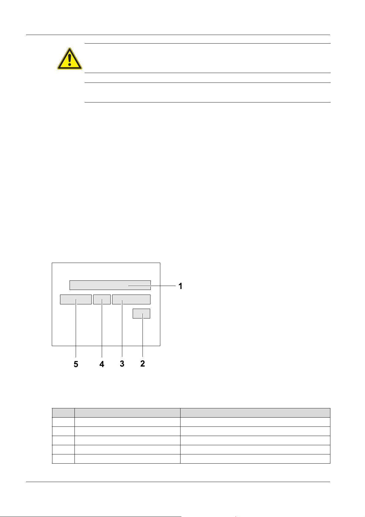
2.9 Product identification of the machine
Data of the nameplate
The nameplate contains information that uniquely identifies this machine. This information is required for
ordering spare parts and when inquiring about technical issues.
Enter information about the machine in the following table:
Item Designation Your information
1 Group and model
2 Year of manufacture
3 Serial number
4 Version no.
5 Item number
7 100_0000_0013.fm
Page 8

3Security
3.1 Policy
In keeping with the latest technological developments
The machine has been built in keeping with the latest technological developments and the recognized
technical safety rules. Nevertheless, improper use can result in hazards to life and limb of the user or
third parties as well as damage to the equipment and other material assets.
Proper use
The machine may only be used for the following purposes:
Soil compaction.
Asphalt compaction.
Vibrating paving stones.
The machine may not be used for the following purposes:
Compaction of very cohesive soils.
Compaction of frozen soils.
Compaction of hard, non-compressible so ils.
Compaction of non-load-bearing soils.
Use in accordance with the intended purpose also includes the observation of all safety instructions in
this manual as well as complying with the prescribed care and maintenance instructions.
Any other or exceeding use is considered improper. The manufacturer's liability and warranty are
canceled for any damage resulting from improper use. The risk lies entirely with the ope rator.
3 Security
NOTE
Please read and observe all notes and safety instructions in this manual. Failure to comply
with these instructions can lead to electric shock, fire and/or serious injury as well as
damage to the machine and/or other objects. Store safety instructions and notes for future
use.
Structural changes
Structural modifications may not be undertaken without the written permission of the manufacturer.
Unapproved structural changes may result in risks to the operator and /or third parties as well as damage
to the machine.
In the case of unauthorized structural changes, the liability and warranty of the manufacturer are no
longer applicable.
The following cases are considered structural changes:
Opening the machine and the permanent removal of components.
Installing spare parts that do not originate from Wacker Neuson or are not comparable in the design
system and quality of the original parts.
Attaching any accessories that do not originate from Wacker Neuson.
Spare parts or accessories that originate from Wacker Neuson can be safely mounted.
3.2 Areas of responsibility of the operator
The operator is the individual who personally operates this machine for industrial or commercial
purposes or who entrusts a third party with the use. The operator bears legal responsibility for his/her
protection as well as that of third parties.
The user must make the operator's manual available to the operator and ensure that this has been re ad
and understood.
The manual must be kept next to the machine or place of use.
The operator must hand over the manual to subsequent operators or owners of the machine.
The country-specific regulations, standards, and guidelines on accident prevention and environmental
protection must be observed. The operator’s manual must be supp lemented with additional instr uctions
that take regulatory, national, or generally applicable safety standards into consideration.
100_0202_si_0008.fm 8
Page 9

3 Security
3.3 User responsibilities
Knowing and implementing the applicable health and safety regulations.
In a risk assessment, risks resulting from on-site working conditions will be determined.
Create operating instructions for the operation of this machine.
Periodically check whether the user instructions correspond to the current state of regulations.
Clearly regulate and specify responsibilities for operation, troubleshooting, maintenance, and
cleaning.
Regularly train employees and inform them about potential hazard s.
Provide employees with the necessary equipment.
3.4 Personnel qualification
This machine may only be installed and operated by trained personnel.
Faulty operation, misuse or operation by untrained personnel can endanger the health of the operator
or third parties and lead to damage to or total loss of the machine.
In addition, the operator should be:
Physically and mentally fit.
Not under the influence of drugs, alcohol or medication that can impair responsiveness.
Familiar with the safety instructions in this manual.
Familiar with the intended use of this machine.
The minimum age (18 years) to operate this machine.
Able to independently operate the machine.
Authorized to operate machines and systems independently according to the standards of safety
engineering.
3.5 General hazards
Residual risks are special hazards involved with handling machines. Despite safety compliant
construction, they cannot be eliminated.
These residual risks are not obvious and can be a source of possible injury or health hazard.
In the case of unforeseen residual risks, immediately stop the machine and inform your supervisor. He/
she will make further decisions and initiate all steps necessary to eliminate the risk.
If required, the machine manufacturer should be informed.
3.6 General Safety Instructions
The safety instructions in this chapter include the "General Safety Instructions", which should be
reported in the manual in accordance with the applicable standards. There may be information that is
not relevant to this machine.
3.6.1 Working area
Before starting work, familiarize yourself with the working environment e.g. load-bearing capacity of
the floor or obstacles in the environment.
Make the working area to public transport safe.
Necessary fuse protection of walls and ceilings e.g. in trenches.
Keep the work area tidy. Cluttered or dark working areas can lead to accidents.
Using this machine in an explosive atmosphere is prohibited.
When using this machine, children and unauthorized individuals must be kept away. Distraction can
lead to loss of control of the machine.
Always protect the machine against tilting, rolling, sliding, and crashing. Risk of injury!
3.6.2 Service
The machine should only be maintained/repaired by technically trained personnel.
Use only original spare parts and accessorie s. Th is en su re s the op er at ion al sa fe ty of th e ma ch ine .
3.6.3 Personal safety
Working under the influence of drugs, alco ho l, or dru gs ca n lead to serio u s injur ies.
Protective equipment should be worn for all work. Appropriate personal protective equipment
considerably reduces the risk of injury.
Remove any tools before the machine is put into operation. Tools that are located on a rotating
machine part can be ejected and cause serious injury.
Always ensure good footing.
9 100_0202_si_0008.fm
Page 10

In the case of extensive work with this machine, long-term vibration-induced damage cannot be r uled
out. For exact values of vibration measurement, refer to the Technical Data chapter.
Wear suitable clothing. Keep loose clothing, gloves, jewelry, and long hair away from moving/rotating
machine parts. Danger of being pulled!
Ensure that no other individuals are in the danger zone!
3.6.4 Handling and use
Handle machines with care. Do not operate machines with defective components or operator’s
controls. Immediately replace defective components or operator’s co ntrols. Machines with defective
components or operator’s controls carry a high risk of injury!
The operator’s controls of the machine shall not be improperly locked, manipulated, or changed.
The machine, accessories, and tools should be used in accordance with these instructions.
Store unused machines out of reach of children. The machine may only be operated by authorized
personnel.
After operation, store the cooled-down machine in a locked, clean, frost-protected, and dry location
that is inaccessible to children and other unauthorize d indiv idu als .
3.7 Specific safety instructions – Vibratory plates
3.7.1 External influences
In the case of the following external influences, the vibratory plate may not be operated:
In heavy rain on sloped surfaces. Risk of slipping!
Oilfield environments – methane leaks from bottom. Risk of explosion!
In dry, flammable vegetation. Fire hazard!
In potentially explosive areas. Risk of explosion!
3.7.2 Operational safety
When operating the machine, make sure that no gas, water, or electric lines are damaged.
The machine must not be operated in tunnels or enclosed spaces.
Pay maximum attention near drops or slopes. Risk of crashing!
The operator must not leave the machine while it is in operation.
Do not leave the machine unattended. Risk of injury!
Delimit spacious workspace and restrict access to unauthorized individuals. Risk of injury!
The operator of the machine must ensure that all individuals keep a minimum distance of 2 m from
the machine while it is in operation.
Do not use any jumper cable sprays. This can cause misfires and engine damage. Fire hazard!
When operating the machine on sloped surfaces, always approach slopes from below and always
stay above the machine on a slope. The machine could slip or tip over.
Do not exceed max. allowable slanting position of the machine – possible failure of the engine
lubrication, see chapter Technical Data.
Only Wacker Neuson use starter batteries. These are vibration proof and therefore suitable for the
high vibration exposure.
3.7.3 Safety distances
Compaction work near buildings can cause damage to buildings. Therefore, all potential effects and
vibrations on surrounding buildings must be checked in advance.
The relevant rules and regulations for measuring, evaluating, and reducing vibration emissions –
especially the DIN 4150-3 – must be considered.
Wacker Neuson assumes no liability for any damage to buildings.
3.8 Specific safety instructions – remote controlled vibratory plates
Always keep remote control and receiving units of the machine clean and free from dry, oil, and
grease.
Remote control and receiving units must not be taped over or covered.
During operation, the remote control should always be aim ed directly a t the machin e. A clea r line of
sight must be maintained – infrared signals can be reflected.
The operator should remain at least 5 meters behind the machine.
3.9 General safety instructions – combustion engines
The following instructions must be complied with:
3 Security
100_0202_si_0008.fm 10
Page 11

3 Security
Before starting work, check the engine to ensure there are no leaks and/or cracks in the fuel lines,
Do not operate a defective engine. Replac e da m ag ed pa rts imme d i at ely.
The pre-set engine speed may not be adjusted. This could lead to engine damage.
Make sure that the exhaust system of the engine is free of debris. Fire hazard!
Switch off before refueling the engine.
Use the correct type of fuel. Fuel should not be mixed with any other fluids.
Use clean filling aids when refueling. Do not spill fuel. Wipe up any spilled fuel immediately.
The engine must not be started in the vicinity of spilled fuel. Risk of explosion!
When operating in partially enclosed spaces, adequate ventilation must be ensured. Do not inhale
The engine surface and exhaust system can quickly become extremely hot. Risk of burns!
Do not open the radiator cap when the engine is hot – Beware of hot coolant!
tank, and fuel cap.
exhaust fumes. Risk of poisoning!
NOTE
This machine is outfitted with an EPA-certified engine.
Changing revolutions per minute (RPM) influence the EPA certification and the emissions.
Settings for this engine may only be changed by a professional.
For more information, contact the manufacturer or your Wacker Neuson contact person.
3.10 General safety instructions – fuel, lubricants and coolants
The following instructions must be complied with:
Always wear safety glasses and protective gloves when handling fuel, lubricants and coolants. If
hydraulic oil, fuel, oil, or coolant gets into your eyes, consult a physician immediately.
Avoid direct skin contact with fuel, lubricants and coolants. Immediately rinse skin with soap and
water.
Do not eat or drink while working with fuel, lubricants and coolants.
Hydraulic oil or fuel contaminated by dirt or water can cause premature wear or failure of the mach ine.
Dispose of replaced or spilled fuel, lubricants and coolants in accordance with the applicable
provisions for environmental protection.
If fuel, lubricants and coolants escape from the machine, immediately cease operation and have it
repaired by your Wacker Neuson contact partner.
3.11 General safety instructions – starter batteries
The following instructions must be complied with:
When disconnecting the starter batter y, alw ays di sconn e c t the ne ga tive terminal first!
When connecting the starter battery, always connect the positive terminal first! Fasten battery
terminal cover!
Flames, sparks, and smoking are prohibited when handling starter batteries.
Starter batteries contain corrosive acid. Wear acid-proof protective gloves and sa fety glasses when
handling starter batteries.
Prevent incorrect connection of the starter battery or bridging of the terminals with tools. Risk of short
circuit!
3.12 Maintenance
The following instructions must be complied with:
This machine may not be maintained, repaired , set, or cleaned while it is switched on. When working
on the electrical system – Disconnect starter battery!
Comply with maintenance intervals.
After any maintenance or repair, the safety devices on this machine must be replaced.
Note maintenance schedule. Any work not perfor med must be undertaken by the service of the
Wacker Neuson contact person.
Worn or damaged machine parts must always be replaced immediately. Only use spare parts from
Wacker Neuson.
Keep the machine clean.
11 100_0202_si_0008.fm
Page 12

Missing, damaged, or illegible safety warning labels should be replaced immediately. Safety stickers
1
3
2
contain important information for the protection of the operator.
Maintenance jobs must be carried out in a clean and dry environment (e.g. in a workshop).
3.13 Personal protection equipment
NOTE
To prevent personal injury when handling this machine, personal protective equipment
must be worn when working on or around this machine.
Pictogram Significance Description
Wear safety shoes! Safety shoes provide protection from bruises, falling
Wear protective gloves! Protective gloves provide protection from abrasion,
3 Security
objects, and slipping.
cuts, punctures, and hot surfaces.
Wear ear protection! Ear protection provides protection from permanent
NOTE
With this machine, the permissible, country-specific noise limit (personal rating level) can
be exceeded. Therefore, ear protection must be worn. For exact values of noise
emissions, refer to the Technical Data section.
When wearing ear protection, remain alert because your ability to hear noises such as
screams or signal tones is restricted.
Wacker Neuson recommends always wearing ear protection.
3.14 Safety equipment
Safety devices protect the user of the machine from potential hazards. These include barriers (gua rds)
or other technical measures. These protect the user from danger. In certain situa tions, the source of risk
is switched off, or the risk is reduced.
This machine has the following safety devices:
hearing impairment.
100_0202_si_0008.fm 12
Page 13

3 Security
Item Description Item Description
1 Protective hood 3 Emergency shutdown switch
2 Automatic central position of control handle
NOTE
Always tighten loose screw connections using the specified torque setting.
Protective hood
The covers protect the operator from hot engine parts and noise.
Emergency shutdown switch
The emergency shutdown switch is used solely to deactivate the machine in the case of danger.
Activating the emergency shutdown switch results in the machine imme diately turning off. Operation can
only be resumed after unlocking the emergency shutdown switch.
Automatic central position of control handle
If the control handle is released in full load, it automatically returns to the central position and the
machine enters stand vibration.
3.14.1 Safety shutdown – Remote-controlled machinery
The machine is operated via an infrared remote con tro l. Fo r safe ty reaso ns , it sw it che s of f
vibration and movement in the following situations:
When the operator enters the proximity area (approx. 1–2 meters from a receiving unit).
When the operator leaves the receiving area (a maximum of 20 meters from the machine).
Interruption of the clear line of sight between the remote control and receiving units of the machine.
Power failure of remote control and/or machine.
3.15 Behavior in dangerous situations
Preventive measures:
Always be prepared for accidents.
Keep first aid equipment on hand.
Make sure that all employees are familiar with accident reporting, first aid, and rescue facilities.
Keep access routes clear for emergency vehicles.
Make sure that employees receive first aid training.
Measures in the case of an emergency:
Immediately take the machine out of operation.
Remove injured and other people from the danger zone.
Initiate first aid measures.
Alert rescuers.
Keep access routes clear for emergency vehicles.
Inform managers at the site.
13 100_0202_si_0008.fm
Page 14

4 Safety and information labels
1
2
3
4
5
6
7
7
8
0219175
0216633
0
2
2
0
0
0
0
WARNING
Illegible symbols
Over time, labels and signs on the machines can become dirty or otherwise
unrecognizable.
Keep all safety, warning, and operating instructions on the machine in a legible
condition.
Replace damaged labels and signs immediately.
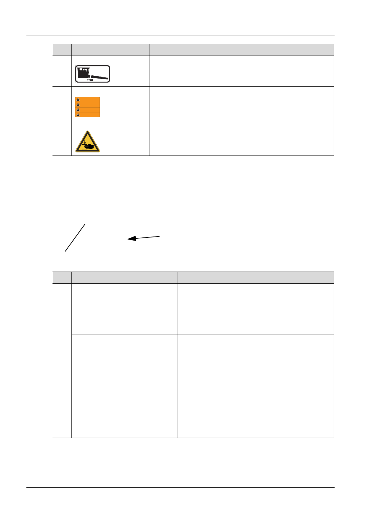
The following labels are found on and in the machines:
4 Safety and information labels
Item Label Description
1 Use personal protection equipment in order to prevent injuries and
health hazards.
Ear protection.
Read operator's manual.
2 Falling machines can cause seriou s injury.
Only lift machine at the central lifting point with certified lifting gear
and tackle (safety load hook).
Do not lift the machine on the central lifting point with an excavator
bucket.
Do not lift the machine on the central lifting point with a forklift.
3 Guaranteed sound power level.
4 Falling machines can cause seriou s injury.
Do not lift the machine with the control handle or center pole.
5 The coolant is under pressure.
Hot coolant can spurt out and cause injury from scalding.
Only open the cover of the radiator after the engine has cooled down.
100_0202_ls_0009.fm 14
Page 15
4 Safety and information labels
0216635
0219261
WARNING
WARNUNG
ADVERTENCIA
ADVERTISSEMENT
0219176
0207747
2
1
Item Label Description
6 Label identifies the remote control in the bracket.
Label identifies the connection of the charging cable for charging.
7 US Machines Warning.
8 Closing the protective hood can lead to crushing wounds.
When closing the protective hood, do not grab between the machine
and the protective hood.
4.1 Safety and information labels on the remote control
The following labels are found on the remote control:
Item Label Description
1 US Machines To preven t interference of the infrared transmission and
possible machine malfunction, do not attach to housing.
Clean before transmitter and receiver eye before
commissioning!
Clean remote control and receiving unit before
commissioning!
2 US Machines To prevent damage and possible malfunction of the
transmitter unit, do not open housing! See operator's manual!
15 100_0202_ls_0009.fm
Page 16

5 Design and function
5.1 Standard package
The machine is delivered fully assemble d an d is rea d y for use ou t of th e bo x.
The standard package includes:
Vibratory plate
Remote control (optional)
Operator’s manual
Manual for machine configuration (includes PIN data of the machine)
5.2 Application areas
The vibratory plate is used for compacting soil. It is used in gardening and landscaping as well as civil
engineering, road construction, and paving.
5.3 Short description
The water-cooled drive motor in the upper mas s hyd raulic ally powers the eccentric weight of the base
plate.
The exciter is designed as a centrally mounted exciter. This principle enables the modification of the
direction of oscillation (by adjusting the eccentric weights) and thus the movement of the machine
(forwards, in reverse or on-the-spot vibration).
For the exciter of the remote controlled machine, eccentric weights can be individually adjusted in order
to allow steering movements. In addition, spot vibration can be adjusted.
The cooler reduces the temperatur e of the engine coolant as well as that of the hydraulic oil.
The intake air is aspirated in the cold area between the cooler and the rear protective hood and purified
via an air cleaner equipped with a pre-cleaner.
The muffler discharges exhaust fumes from the front.
To start the drive motor automatically, the glow plugs are preheated. The speed of the drive motor is
controlled via a lifting magnet. The machine is switched off via an electrically controlled solenoid valve
on the fuel filter.
The electrical control unit is located in the electrical box.
The operator’s controls are located on the electrical box and the center pole head.
The maintenance-free starter ba tte r y is loca ted below the bracket for the remote control.
The machine is controlled with the center pole. For the remote controlled machine, it is controlled
exclusively via the remote control.
5.3.1 Remote-control vibratory plate
The machine is controlled exclusively by the remote control.
Within the receiving area, the commands of the remote control are transmitted to the machine via
infrared signal.
For trouble-free transmission of the infrared signal, the remote control must always be aimed directly at
one of the receiving units of the machine.
5 Design and function
The following commands are possible with the remote control:
Start engine.
Move machine with simultaneous vibration.
Switch spot vibration on and off.
Move machine slow or fast.
Switch off engine.
Infrared system
If the remote control has been activated by pressing the ON/OFF switch, it permanently sends infrared
signals to the respective receiving unit of the machine.
The receiving unit of the machine converts the infrared signal into an electrical signal. The contro l
electronics process the electrical signal and control the machine in accordance with the control
command.
100_0202_sf_0010.fm 16
Page 17

5 Design and function
Image in progress
In order for the machine to be able to execute the control commands, the remote control and machine
must be set to the same transmission channel.
Each machine has its own address for the transmission channel. Upon delivery, the transmitter unit is
set to the address of the machine and will only work with this machine. If the transmitter unit operates
another machine, this can be adjusted, see Setting the transmission channel (remote control) chapter.
If multiple remote controlled machines are operated in close proximity, the machines must be set to
different transmission channels.
Receiving area
Operation is only possible when the machine is within the receiving area. The receiving area is
approximately 20 meters from a receiving unit of the machine.
Within the receiving area, there must always be a clear lin e of sight between the re mote control and th e
machine. If there is no clear line of sight, the machine will cease all vibration and movement.
Outside of the receiving area, the machine will not receive the commands. The machine will stop
vibrating and moving.
Proximity area
If the machine comes within 1–2 meters (proximity area) of the operator, it will cease all vibration and
movement. Once the operator leaves the proximity area, the machine is once again able to receive
commands.
If the operator is laterally closer than 1–2 meters from th e machine or if the infrared signals of the remote
control are transmitted via reflection, a stopping of the vibration and movement is not guaranteed.
If another person comes within 1–2 meters (proximity area) of the machine, the machine will not cease
vibration and movement. The shutdown in the proximity area only works in conjunction with the remo te
control unit.
5.3.2 Diagnostic system
The diagnostic system of the machine consists of control electronics and sensors that monitor various
components of the machine.
If the diagnostic system detects a fault or an error, this is signale d to the receiving unit by solid or flashing
red lights. A fault indication with error code appears on the display.
Each error code stands for a specific fault. The diagnostic system can distinguish between approx. 30
error codes.
In case of serious faults, the error code is entered into the error memory, and the machine will
automatically switch off the motor or deactivate itself.
5.3.3 Machine configuration system
In the machine configuration system, machine parameters can be changed by the user (e.g. switching
an activation PIN on or off).
17 100_0202_sf_0010.fm
Page 18

5.3.4 Machine protection – installation (optional)
The acceleration load of the upper mass is monitore d via a machine protection sensor. When a threshold
value corresponding to operation of the vib ratory plate on an extremely hard surface (concrete, asphalt)
is exceeded, a warning is given to the ope rator. This wa rning is that the control lamp on the center pole
head or the receiving unit will flash red.
In addition, the machine will respond in one of the following ways (adjustable in the machine
configuration):
Only an entry in the error memory.
Lowering the excitation speed.
Shutdown of the machine with entry in the error memory.
Switching to slow mode.
5.3.5 Compatec – compaction display (optional):
Compatec – compaction display is attached to the rear protective hood and is within the op erator ’s lineof-sight. The display, which consists of eight light-adjusting LEDs, displays the relative compaction
progress by successively lighting up. When the number of illuminated LEDs no longer increases, this
means that no further compaction can be achieved with the machine. The operator can finish the work
and avoid unnecessary passes or over-compaction of the soil.
The overload display indicates if the machine is being operated on too hard of a surface. The operator
is notified of this through rapid flashing of all eight LED's.
Compatec – compaction display is suitable for all highly compactable and mixed-grained soils.
5 Design and function
5.4 Versions
This operator’s manual covers the following models:
Versions Description
r Remote start
m Machine protection – installation
c Compatec – compaction display
NOTE
Compatec – compaction display only supports soil compaction and does not replace the
professional measuring of soil density by an expert.
100_0202_sf_0010.fm 18
Page 19
6 Components and operator's controls
2
3
1
5
6
7
10
4
6 Components and operator's controls
6.1 Components
Item Designation Item Designation
1 Drive motor 6 Central lifting point
2 Upper mass 7 Eyelet for padlock
3 Base plate 8 Receiving units
4 Center pole 9 Bracket for remote control and charging
cable
5 Fuel tank 10 Nameplate
Center pole
The center pole can be adjusted to the optimum working height.
Central lifting point
The central lifting point is used to lift the machine. When the overall height is a deciding factor, the central
lifting points can be folded.
Receiving units
On the remote controlled machine, there are two receiving units (front and r ear) with an integrated status
display. Depending on the position of the operator, the front or rear receiving unit receives the
commands of the remote controller via infrared signal.
The integrated status display uses lights and flashing signals to indicate the current operating status of
the machine.
To better distinguish between the front and rear of the machine, the rece iving units have different colors.
Eyelet for padlock
The rear protective hood features a lug for attaching a padlock. The machine is thus protected against
unauthorized opening of the rear protective hood as well as unauthorized operation.
Bracket for remote control and charging cable
The bracket is used to store and charge the remote control unit as well as to protect it against damage
and theft.
6.2 Operator’s controls
Always keep the display and operator’s controls on the machine clean, dry, and free of oil and grease.
Operator's controls such as the ON/OFF switch, and throttle control handles may not be locked,
manipulated, or changed without permission.
19 100_0202_cp_0006.fm
Page 20
6 Components and operator's controls
2
3
4
5
6
7
11
8
9
10
1
Item Designation Item Designation
1 Hood opener 7 Vibratory rammer
2 ON/OFF switch (red) 8 Control handle
3 Display and control lamps (diagnostic and
configuration menu)
4 Adjusting key (black) 10 Footrest of center pole lock
5 Start button 11 Emergency shutdown switch
6 Slow/fast rocker switch
9 Height adjustment mechanism of center pole
Control handle
The control handle is used to continuously regulate the speed and travel direction.
Footrest of center pole lock
The footrest of the center pole lock is used to release the center pole from the transport position so that
it can be returned to working position. The individually adjusted working height is maintained.
Emergency shutdown switch
The emergency shutdown switch is used solely to deactivate the machine in the case of danger.
Activating the emergency shutdown switch results in the machine immediately turn ing off. Operation can
only be resumed after unlocking the emergency shutdown switch.
Height adjustment mechanism of center pole
The center pole height-adjustment mechanism allows for con tinuous height adjustment in order to adjust
the center pole individually to the optimum working height. This is done by turning the star knob.
In addition, by pushing down on the star knob, the center pole can be b rought into the lower position e.g.
to be able to travel through low passages. If the center pole is raised , the respective optimal ly adjusted
working height is once again active.
ON/OFF switch (red)
With the red ON/OFF switch, the machine is activated for starting with the start button on the center pole
head or remote control.
The machine is completely deactivated with the ON/OFF button.
With the ON/OFF switch, the diagnostic and configuration menus can also be called up and menu items
can be changed.
Setting key
With the black setting key, digits of the activation PIN, setup PIN, or machine settings can be adjusted.
100_0202_cp_0006.fm 20
Page 21

6 Components and operator's controls
1 2 3 4 5 6
7
Display and control lamps
Item Designation Item Designation
1 Control lamp for operation 5 Control lamp for oil pressure
2 Control lamp for charging 6 Control lamp for coolant temperature
3 Control lamp for preheating 7 Display
4 Control lamp for air cleaner
Control lamp for operation
The control lamp for operation indicates whether the machine has been activated via the ON/OFF switch.
The control lamp for operation lights up green when the machine has been activated via the ON/OFF
switch.
The control lamp for operation goes out when the machine has been deactiva ted via the ON/OFF
switch.
Control lamp for charging
The control lamp for charging indicates whether the starter battery of the machine is being charged.
The control lamp for charging lights up red when the machine is activated.
The control lamp for charging goes out when the engine is running.
The control lamp for charging lights up red when the starter battery of the machine is no longer
charged.
Control lamp for preheating
When the engine is started, the control lamp for preheating indicates whether the glow plugs are being
preheated.
The control lamp for preheating lights up yellow as long as the glow plugs of the engine are preheated
during starting.
The control lamp for preheating goes out when preheating is completed.
Control lamp for air cleaner
The control lamp for the air cleaner displays the maintenance condition of the air cleaner .
The control lamp for the air cleaner lights up yellow when the air cleaner is dirty.
Control lamp for oil pressure
The oil-pressure control lamp indicates whether the oil pressure is sufficient.
The control lamp for oil pressure lights up red when the machine is activated.
The control lamp for oil pressure goes out when the engine is running.
The control lamp for oil pressure lights up red when the oil pressure is too low.
Control lamp for coolant temperature
The control lamp for coolant temperature indicates whether the coolant temperature is within the
permissible range.
The control lamp for coolant temperature lights up red when the coolant temperature is too high.
21 100_0202_cp_0006.fm
Page 22

6 Components and operator's controls
Diagnostics
Setup
Display
The following information is displayed in sequence:
Number of operating hours.
The transmission channel set on the machine.
Error statuses.
Diagnostic menu.
Configuration menu.
Diagnostic menu
In the diagnostic menu on the display, the following information about the machine can be accessed:
Overview of all detected errors (error memory).
Starter battery voltage.
Coolant temperature of the engine.
Hydraulic oil temperature.
Engine speed.
Software version (SW version).
Switch test.
IR transfer
Configuration menu
NOTE
The operation of the configuration menu is described in the manual for machine
configuration.
In the configuration menu on the display, the following machine settings can be adjusted:
Change setup PIN.
Change/activate/deactivate activation PIN of the machine.
Setting turn-off time of the machine.
Select the display language (English, German, French, or Spanish).
Adjust machine response in the case of overload (overload sensor).
Setting the hydraulic parameters/centrifugal force.
100_0202_cp_0006.fm 22
Page 23
6 Components and operator's controls
1
1
2
33
4
8 7 6 5
11 10 9
6.3 Components and operator’s controls – remote control unit
The remote control of the DPU 80r and DPU 100r may only be used for these machines.
Item Designation Item Designation
1 Joystick (left, right) 7 Engine start button
2 Socket for charging cable 8 ON/OFF switch
3 Carrying strap 9 Control lamp for charging
4 Rechargeable battery 10 Control lamp for operation
5 Spot compaction button 11 Diagnostic control lamp
6 Button for slow/fast operation
Joystick (left, right)
By pressing the joystick, the vibration starts, and the machine moves.
ON/OFF switch
The remote control unit is switched on via the ON/OFF switch. When switching off, the remote control
and the engine are turned off.
Engine start button
The start button starts the engine.
Button for slow/fast operation
The slow/fast button is used to switch between slow and fast operation. Fast operation is selected by
default.
Quick mode – operating mode for compacting.
Slow operation – mode with reduced engine speed to traverse highly compacted or hard surfaces.
Spot compaction button
The spot vibration button must remain pressed so that the machine compresses on the spot.
Carrying strap
The carrying strap is used to hang the remote control.
Rechargeable battery
The rechargeable battery powers the remote control unit. The rechargeable battery can be recharged
with the charging cable of the machine or with an external battery charger.
23 100_0202_cp_0006.fm
Control lamps
Charging
The control lamp for charging lights up green when the rechargeable battery is charging.
The control lamp for charging goes out once the rechargeable battery is charged.
Page 24

6 Components and operator's controls
Operation
Operation control lamp flashes green when the remote control is switched on.
The control lamp for operation flashes green when the remote control is switched on.
The control lamp for operation flashes red when the char ge situation of the battery is low.
The control lamp for operation lights up red when the rechargeable battery is discharged.
Diagnostics
The control lamp for diagnosis briefly flashes green when a joystick is moved or a button on the
remote control unit is pressed.
100_0202_cp_0006.fm 24
Page 25

7 Transport
1
2
7 Transport
WARNING
Improper handling can result in injury or serious material damage.
Please read and follow all safety instructions in this operator’s manual.
DANGER
Danger from falling.
Falling machines can cause serious injury e.g. through crushing.
Only use suitable and tested lifting gear and t ackle (safety load hooks) of sufficient
lifting capacity.
Only lift the machine from the central lifting point.
Reliably secure the machine to the lifting gear.
Do not lift the machine on the central lifting point with a forklift or excavator bucket.
Do not lift the machine at the control handle.
Evacuate danger zone while lifting, do not stop under susp ended loads.
WARNING
Fire and explosion hazard from fuel.
Leaking fuel can ignite and cause serious burns.
Lift and transport the machine in an upright position.
7.1 Loading and transport
Carry out preparations
Item Designation Item Designation
1 Center pole 2 Center pole lock
When loading and transporting, the center pole must be locked into place by engaging the center pole
lock in the vertical position.
25 100_0202_tr_0009.fm
Page 26
Lift machine
1
2
NOTE
Establish a flagman for a secure lifting process.
Item Designation Item Designation
1 Central lifting point (attachment point) 2 Tie-down lugs
7 Transport
1. Place the central lifting point in the vertical position.
2. To lift the motor, hang suitable tackle at the central lifting point.
3. Carefully load machine into or onto a stable means of transport.
4. After loading the machine, lash down the machine to prevent it from rolling off, slipping,
or tipping over. Attach tie-down lugs to the designated lashing points.
100_0202_tr_0009.fm 26
Page 27

8 Operation and use
1
2
8 Operation and use
WARNING
Improper handling can result in injury or serious material damage.
Please read and follow all safety instructions in this operator’s manual.
8.1 Before commissioning
8.1.1 Inspection before commissioning
Open protective hoods
Item Designation Item Designation
1 Hood opener of rear protective hood 2 Hood opener of front protective ho od
1. Pull hood opener of rear protective hood until it is unlocked. Completely open protective hood.
2. Pull hood opener of front protective hood until it is unlocked. Completely open protective hood.
Complete the following inspections:
Check machine and components for damage. If there is any visib le damage, do not use the machine
and immediately contact the Wacker Neuson service.
Ensure that loose packing material has been removed from the machine.
Ensure that there are no loose items under the protective hood e.g. gloves or tools.
Check fuel level.
Check engine oil level.
Check hydraulic oil level.
Check fuel lines for leaks.
Make sure the screwed connections are firmly in place.
Receiver units are free of dirt.
NOTE
Perform tests in accordance with maintenance chapter, top up any missing fuel, see
technical data chapter.
27 100_0202_op_0011.fm
Page 28

8.1.2 Set center pole
1
2
Image in progress
Item Designation Item Designation
1 Center pole 2 Star knob
The optimum working height of the center pole can be adjusted by turning the star knob.
8.1.3 Remote controlled machine
Remove remote control from the bracket
8 Operation and use
Item Designation Item Designation
1 Remote control 4 Bracket for charger cable
2 Bracket for remote control 5 Socket with screwed nose cap
3 Charge cable
1. Pull hood opener of rear protective hood until it is unlocked.
2. Completely open the rear protective hood with the hood opener.
3. Unscrew the char ging ca ble fro m th e re mote c ontr ol.
4. Place charging cable in the bracket.
NOTE
Improper handling can result in damage to the charging cable.
When placing charging cable in the bracket, make sure it will not get pinched when
closing the protective hood.
5. Screw screwed nose cap on the connection socket of the remote control.
6. Remove the remote control from the bracket.
100_0202_op_0011.fm 28
Page 29
8 Operation and use
Image in progress
Check remote control
Remote control and carrying strap are undamaged.
Remote control is free of dirt.
8.2 Notes on operation
WARNING
Danger of tipping
There is a serious risk of injury from slipping or tipping over of the machine.
Near edges, at least 2/3 of the machine must be on a load-bearing surface.
If not, decommission the machine and lift back on a load-bearing surface.
WARNING
Health hazard from exhaust fumes
The exhaust fumes of this engine contain chemicals, which the state of California
knows can cause cancer, birth defects or other reproductive damage.
Operation on sloped surfaces
Within the area of a slope, always stand above the machine.
Only approach gradients from below (a gradient that can be easily driven up can also be driven down
without any risk).
Not stand in the direction of descent of the machine.
Do not exceed the maximum allowable slantin g position (see Technical Data) chapter.
Only operate the machine for a short time in maximum allowable slanting position.
NOTE
If the maximum permissible slanting position is exceeded, this results in a failure of the
engine lubrication and therefore inevita b l y ca uses a defect of important engine parts.
Remote-controlled machinery – locational information
Item Designation Item Designation
1 Front (transparent receiving unit) 3 Rear (rear receiving unit)
2 Right 4 Left
29 100_0202_op_0011.fm
Page 30
8 Operation and use
Image in progress
Image in progress
1
2
3
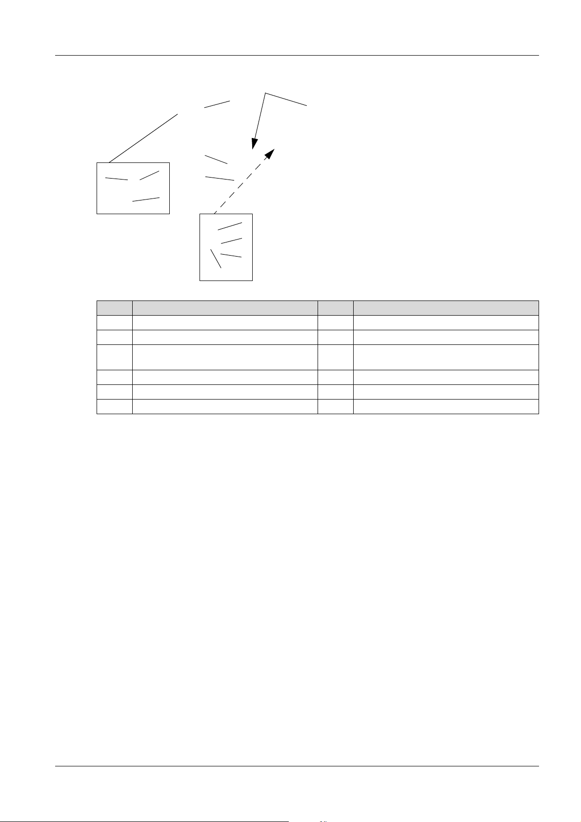
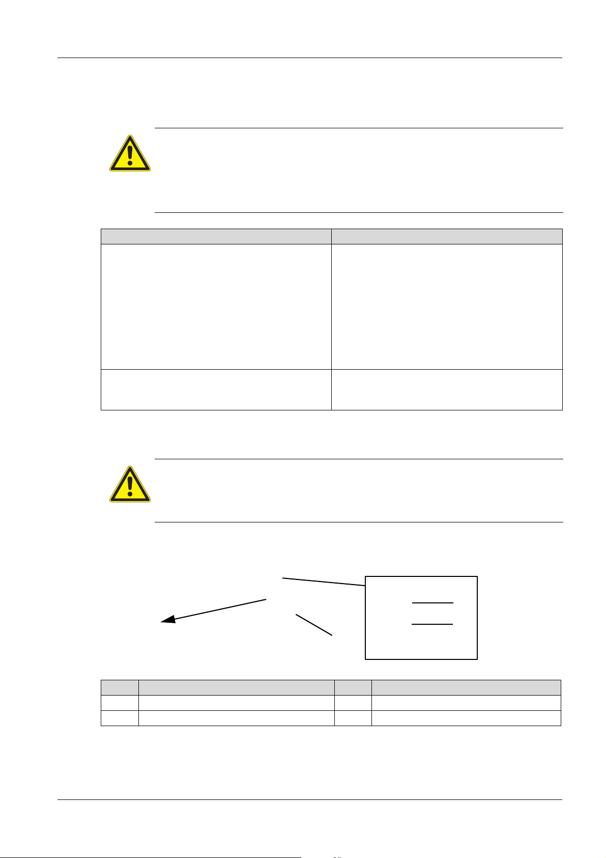
Remote-controlled machinery – direction of movement
The direction of movement of the machine is independent from the position of the operator. If the joystick
of the remote control is pressed forward, the machine moves always forward.
WARNING
Mixing up the direction of movement of the machine poses a dang er of crushing for others.
Operate the machine from behind and maintain a minimum safety distance of at least
2 meters.
Ensure that no other individuals are in the proximity area or working area of the
machine.
Operator behind the machine Operator in front of the machine
If the operator is located behind the machine and
presses both joysticks forward – the machine
moves forward away from the operator.
8.3 Commissioning
DANGER
Fire hazard
Jumper cable sprays are highly flammable; they can ignite and cause severe burns.
Do not use jumper cable sprays.
8.3.1 Activate machine
If the operator is located in front of the machine
and presses both joysticks forward – the machine
moves backward away from the operator.
Item Designation Item Designation
1 Control lamps 3 ON/OFF switch (red)
2 Display
1. Pull hood opener of rear protective hood until it is unlocked.
2. Completely open the rear protective hood with the hood opener.
3. Press the ON/OFF switch on the machine.
100_0202_op_0011.fm 30
Page 31

8 Operation and use
1
2
3
4
0XXX
When the machine is activated, all control lamps light up for approx. 1 second.
The following are displayed in sequence:
Auto-engaging status.
The transmission channel set on the machine (optional).
Possibly the most recent error.
Number of operating hours.
4. Close and lock rear protective hood into place.
Enter activation PIN
NOTE
PIN entry is deactivated by default. If the machine should be secured by an activatio n PIN,
this must be set in the configuration menu; see Manual for Machine Configuration.
The activation PIN should always be kept secret and never be listed on the machine or
remote control.
Item Designation Item Designation
1 Digit of the activation PIN 3 ON/OFF switch (red)
2 Position of the activation PIN 4 Adjusting key (black)
NOTE
The engine can only be started if the correct activation PIN has been entered with the
remote control.
1. When the display prompts you to enter the activation PIN, press the ON/OFF switch.
2. Enter activation PIN:
NOTE
If an incorrect PIN is entered four times in succession, you must wait five minutes before
re-entering the PIN. During the wait time, the request to wait is displayed.
To select the next position, press the ON/OFF switch on the machine.
To select the digit, press the selection button repeatedly until the correct value is achieved.
3. Once all of the digits of the activation PIN have been selected, press the ON/OFF switch of the
machine.
31 100_0202_op_0011.fm
Page 32

8.3.2 Commission machine (center pole)
1
2
1
2
Item Designation Item Designation
1 Start button 2 Control lamp
8 Operation and use
1. The red control lamp on the center pole flashes briefly at intervals of 5 seconds to signal readiness
to start.
2. Briefly press start button of the center pole – the motor will start automatically.
NOTE
The starting process can take up to 2 minutes. As long as the control lamp is red, the
automatic start up runs. Depending on the operating temperature of the e ngine, the glo w
plugs are optionally preheated and warmed up.
8.3.3 Commission machine (remote control)
Switch on remote control unit
Item Designation Item Designation
1 Control lamp for operation 2 ON/OFF switch
1. Press the ON/OFF switch of the remote control unit Operation-control lamp flashes green when the
remote control is switched on.
NOTE
If the operation-control lamp flashes or lights red, recharge the rechargeable battery.
2. Hang the remote control with the carrying strap.
100_0202_op_0011.fm 32
Page 33

8 Operation and use
1
1
2
Start engine
Item Designation
1 Engine start button
1. Directly aim remote control towards a receiver unit.
2. Briefly press start button of the remote control – the motor will start automatically. When the receiving
units flash yellow, the machine is ready.
NOTE
The starting process can take up to 2 minutes. As long as the receiving units light red, the
automatic startup will run. Depending on the operating temperature of the en gine, the glow
plugs are optionally preheated and warmed up.
Machine with Compatec – compaction display (optional)
Item Designation Item Designation
1 Compatec – compaction display 2 LEDs/light progress bar
1. During the first few seconds after starting the machine, a li ght progr ess bar appear s on Compate c –
compaction display.
2. LEDs light up starting from left to right.
NOTE
If all LEDs light up, the system is fault-free. The LEDs will then switch off one after the
other.
3. All LEDs will briefly light up again at reduced brightness.
4. The sensor is thus successfully tested and Compatec – compaction display is ready for operation.
NOTE
If all LEDs permanently light after initialization, the sensor has not been successfully
tested; see troubleshooting chapter.
8.4 Operation
In accordance with the intended purpose, the operator should stand behind the machine.
Guide and steer machine using the control handle.
Control machine with remote control.
33 100_0202_op_0011.fm
Page 34

8.4.1 Operate machines with center pole
1
2
3
4
1
Item Designation Item Designation
1 Vibratory rammer 3 Forward
2 Central position of control hand le 4 Reverse
1. Pull vibration switch
2. Select travel direction and speed with the control handle.
Speed display by lighting of the slow/fast-rocker switch or flashing for intermediate positions.
8 Operation and use
Switch slow/fast mode on and off
Item Designation
1 Slow/fast rocker switch
Slowly press the slow/fast switch up to increase the speed.
Slowly press the slow/fast switch down to reduce the speed.
If the warning vibration-control lamp lights up, the maximum speed is set.
If the vibration-control lamp lights up, the speed is lower than maximum.
NOTE
To switch from maximum to minimum (or vice versa) speed, the slow/fast operation button
must be pressed for approx. 2–3 seconds.
100_0202_op_0011.fm 34
Page 35

8 Operation and use
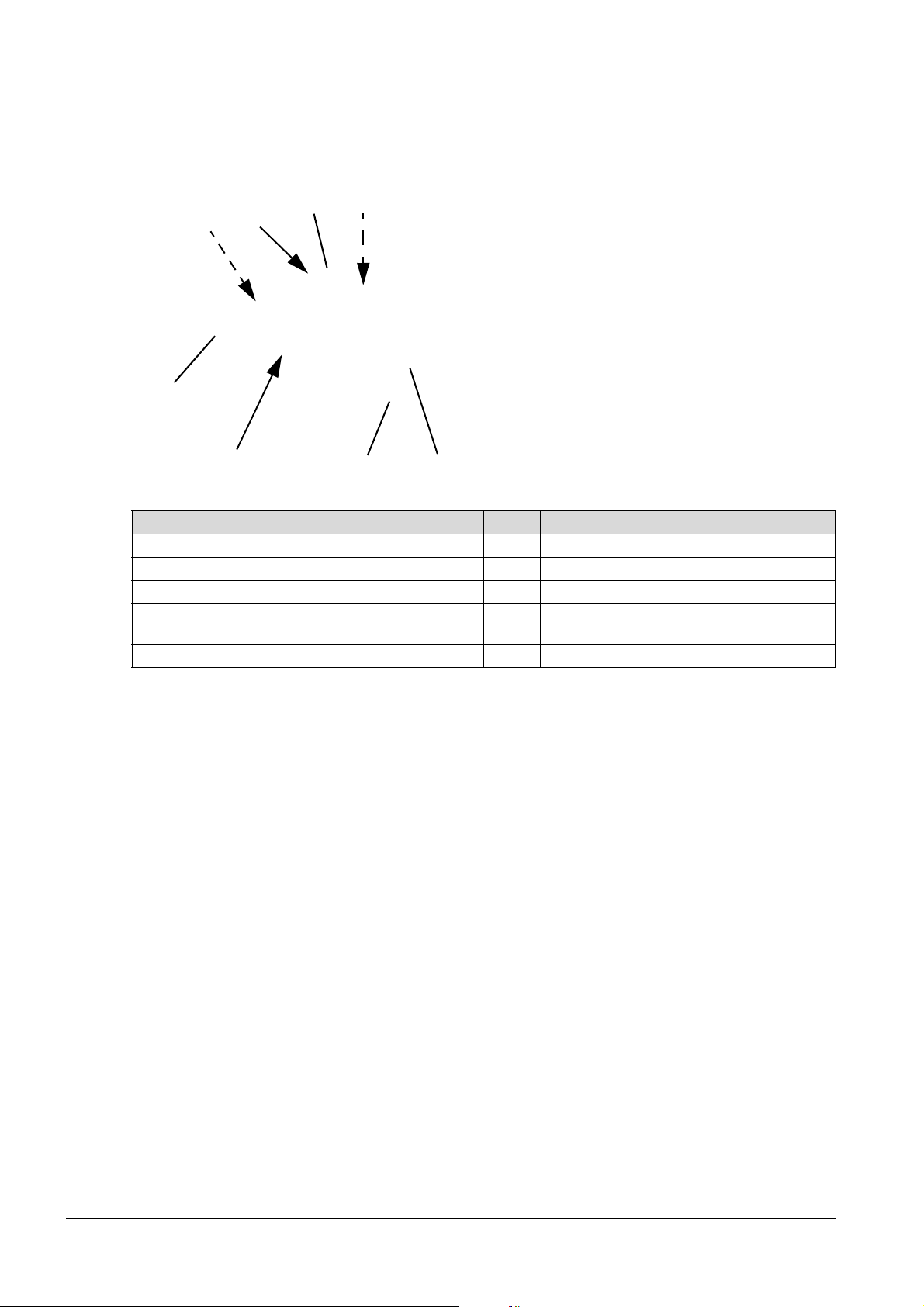
8.4.2 Operating a remote-controlled machine
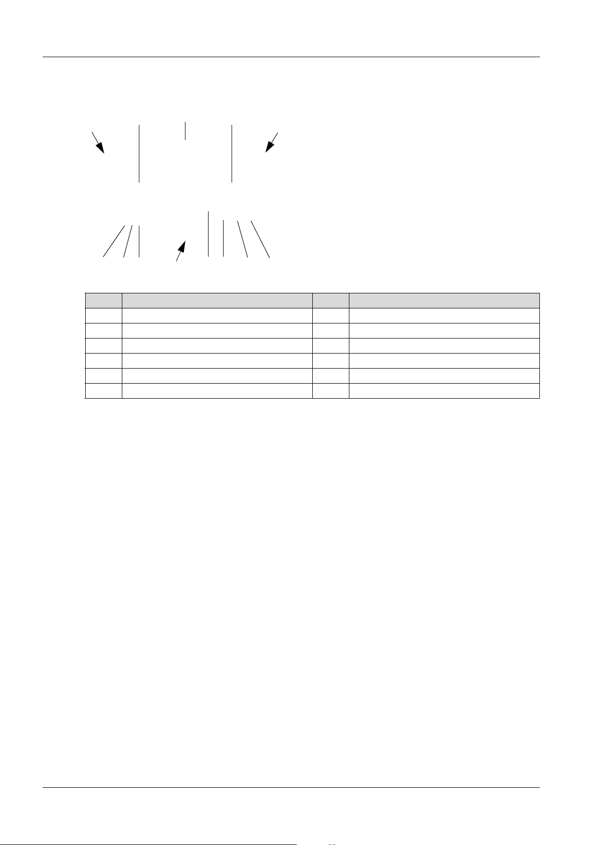
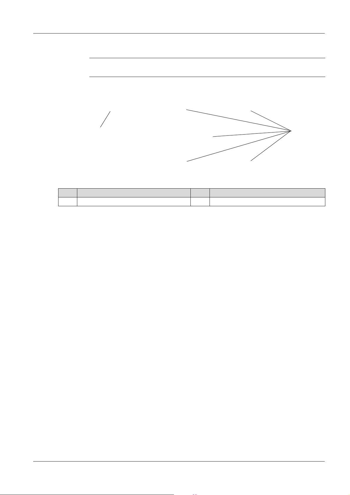
The following table shows how the machine moves when the respective joystick of the remote
control is operated:
Forward Reverse
Forward left turn Forward right turn
Reverse left turn Reverse right turn
Left stand rotation Right stand rotation
No movement
Moving and stopping the machine
1. Press the joystick of the remote control to the desired position and hold. The machine star ts vibrating
and moves in the desired direction – the further the joysticks are pushed forward or backward, the
faster the machine moves.
2. Release both joysticks of the remote control. The machine stops moving and vibrating – after approx.
6 seconds, the engine switches to idle.
Switch slow/fast mode on and off
NOTE
Fast operation is selected by default.
The slow mode is only intended for traversing highly compressed or hard surfaces.
1. Press slow/fast mode button to switch between slow and fast operation.
When the receiving units flash yellow, the machine is in slow mode.
Switching stand vibration on and off
1. Pressing and holding stand vibration button – The machine compresses on the spo t without mo ving
in one direction.
2. Releasing stand vibration button – The machine will return to normal operating condition.
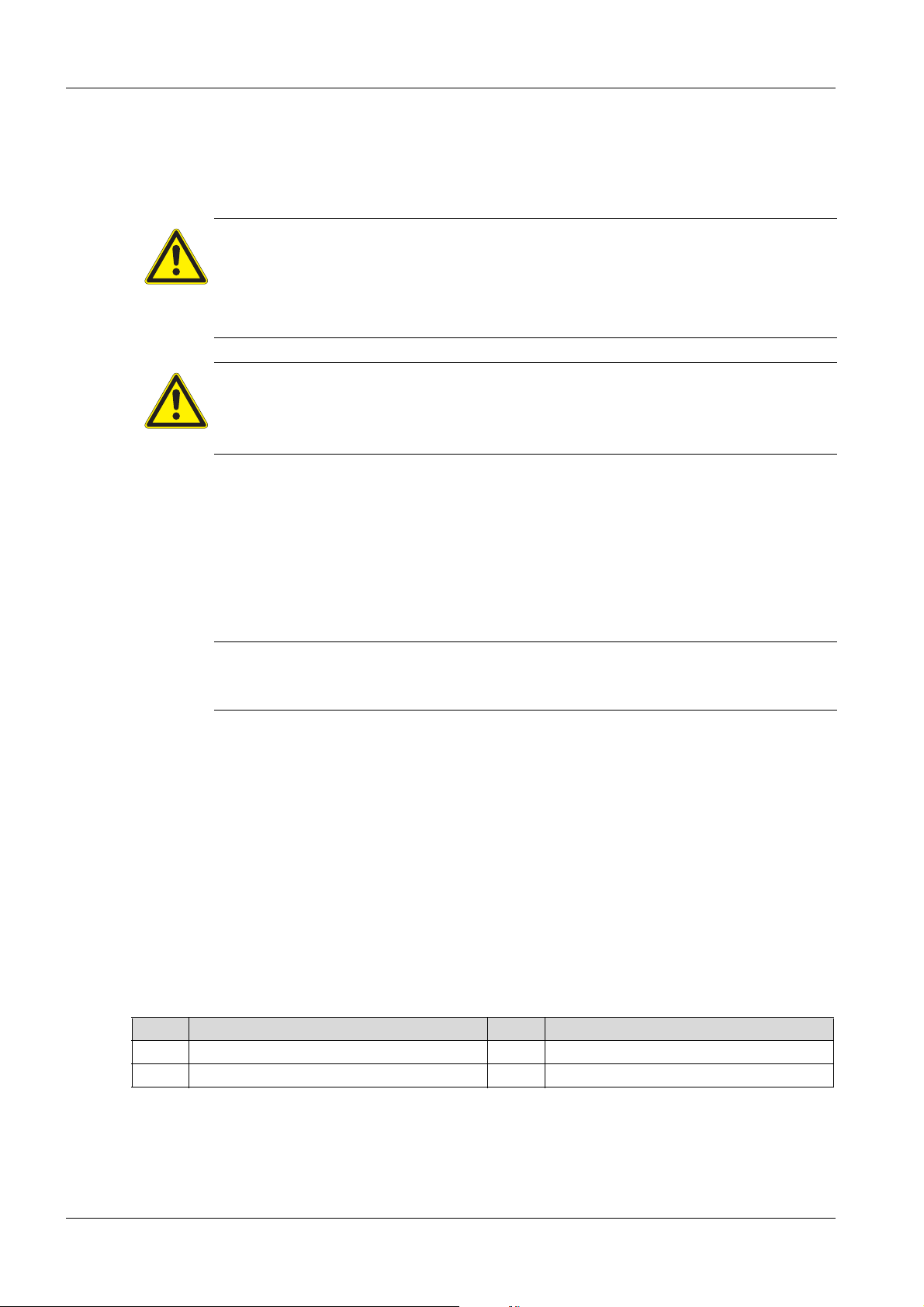
8.4.3 Machine protection – installation
To protect the machine, an warning is activated when compacting:
The red control lamps on the center pole flash.
The receiving units flash red.
In addition, a machine response can be set in the configuration menu:
Switching off the machine.
Switching to slow mode.
Reduced power operation.
35 100_0202_op_0011.fm
Page 36

8.4.4 Reading Compatec – compaction display
2
1
This display roughly indicates the progress of the compaction.
NOTE
To protect the machine, Compatec – compaction display warns the operator of overcompaction by quickly flashing all LEDs.
NOTE
The brightness of the LED automatically adjusts to the light cond itions of the working area.
The number of LEDs lit is proportional to the soil density, more illuminated LEDs corresponds to a
higher soil density.
NOTE
It is possible to detect non-compactable material if the spot is longer than one mete r.
In the case of abrupt change from high to low-compacted soil (or vice versa), there is a
slow increase or decrease of the LEDs.
8 Operation and use
NOTE
If the machine is operated in reduced power mode
Preselected using the slow/fast rocker switch or button.
Overload setting in the configuration menu.
No LEDs of Compatec - compaction display are lit.
NOTE
Functionality of the machine protection - installation see chapter machine protection installation.
8.5 Decommissioning
8.5.1 Decommissioning the machine (center pole)
Item Designation Item Designation
1 Vibratory rammer 2 Start button
1. Press vibration switch – Vibrat io n switches off and machine stops.
100_0202_op_0011.fm 36
Page 37

8 Operation and use
1
2
2. Press the start button – the engine switches off.
NOTE
Compatec - compaction display automatically switches itself off once the machine is
turned off.
8.5.2 Decommissioning the machine (remote control)
Switch off remote control and engine
Item Designation Item Designation
1 Control lamp for operation 2 ON/OFF switch
1. Release both joysticks of the remote control.
2. Directly aim remote control towards a receiver unit.
NOTE
If the remote control is not directly aimed at the receiving unit, only the remote control will
be switched off.
3. Press the ON/OFF switch of the remote control to turn off the engine and remote control – the
operation control lamp switches off when the remote control is switched off.
NOTE
The remote control will automatically switch itself off after approx. 10 min.
8.5.3 Deactivate machine
WARNING
Operation of the machine by unauthorized persons can lead to serious injury.
Ensure that no unauthorized persons have access to the machine and remote control.
Always keep the remote control in a safe place, e.g. within the locked machine.
37 100_0202_op_0011.fm
Page 38

8 Operation and use
1
2
3
1
Item Designation Item Designation
1 Control lamps 3 ON/OFF switch (red)
2 Display
1. Open rear protective hood.
2. Press the ON/OFF switch on the machine in order to deactivate it. If the operation an d receiving u nit
control lamps turn off, the machine is deactivated.
3. Charge rechargeable battery of the remote control with the charger cable.
4. Close rear protective hood.
NOTE
If the machine is not deactivated, it will automatically deactivate after approx. 1 hour
(factory default setting).
The turn-off time can be set in the configuration menu.
Decommissioning machine in an emergency situation (emergency stop)
NOTE
The emergency shutdown switch is a safety device and should only be used for the
immediate shutdown of the machine in th e cas e of an em er ge n cy situ at ion .
Item Designation
1 Emergency shutdown switch
1. Pressing the emergency shutdown switch – the machine will immediately stop moving and vibration
and will automatically deactivate itself.
To unlock, turn the emergency shutdown switch to the left. The machine can then be re-activated.
100_0202_op_0011.fm 38
Page 39

8 Operation and use
Image in progress
8.5.4 Charge rechargeable battery (remote control)
NOTE
Charging the battery at temperatures below 0°C may not be possible.
Charging rechargeable battery with charging cable
NOTE
After connecting the charging cable to the remote control, the rechargeable battery is
loaded. Overcharging the battery is not possible; the charging cable must not be
disconnected from the remote control after charging. Note that after a longer downtime/
service life of the machine, the rechargeable battery char ges more slo wly. It may need to
be recharged.
A charging time of 15 min is sufficient to operate the machine for about 1 hour.
Connecting the charging cable
Item Designation Item Designation
1 Remote control 4 Bracket for charger cable
2 Bracket for remote control 5 Socket with screwed nose cap
3 Charge cable
NOTE
Improper handling can result in damage to the charging cable.
When using charging cable, make sure it will not get pinched when closing the
protective hood.
1. Open rear protective hood.
2. Unscrew screwed nose cap from the connection socket of the remote control.
3. Remove the charging cable from the bracket.
4. Plug charger cable into the connector on the remote control and screw in.
NOTE
The loading of the remote control lamp lights up green when the rechargeable battery
is charging.
The loading of the remote control lamp goes out once the rechargeable battery is
charged.
5. Place remote control in the bracket.
6. Close rear protective hood.
39 100_0202_op_0011.fm
Page 40

8 Operation and use
1
2
8.5.5 Rechargeable battery charger with external charging device (optional)
Only use external battery chargers from Wacker Neuson.
Remove rechargeable battery from the remote control
Item Designation Item Designation
1 Rechargeable battery 2 Clip
1. Press the clip and simultaneously pull the rechargeable battery to the right.
Rechargeable battery charger wit h exte rn al ch a r gi ng de v ice
Item Designation Item Designation
1 Plug receptacle 3 Rechargeable battery
2 Status control lamp
NOTE
Before the first charging, read the operator’s manual for the battery charger.
1. Insert rechargeable battery into external battery charger.
2. Connect country-specific connector to the battery charger.
3. Insert the plug of the battery charger into the plug receptacle.
NOTE
The status control lamp lights up ora nge when the rechargeable battery is charging.
The status control lamp flashes orange when the rechargeable battery is completely
charged.
4. Once the rechargeable battery is charged, remove the plug from the socket.
5. Remove rechargeable battery from the external battery charger.
Insert rechargeable battery into the remote control
100_0202_op_0011.fm 40
Page 41

8 Operation and use
1. Push rechargeable battery into the remote control until the clip snaps into place.
8.6 Setting the transmission channel (remote control)
The machine can only be operated if the transmission channel of the remote control corresponds to the
transmission channel of the machine. The supplied remote control corresponds uniquely with each
machine.
The IR address is displayed:
Label on decoder in the electrical box.
In the display after the machine activation.
In the following cases, an adjustment of the transmission channel may be requ ired:
If the remote control has been replaced by another.
Synchronize transmission channel between remote control and machine.
1. Switch on remote control unit.
2. Activate machine.
3. Remove the charging cable from the bracket.
4. Unscrew screwed nose cap from the connection socket of the remote control.
5. Plug charger cable into the connector on the remote control and screw in.
6. Directly aim remote control towards the receiver unit.
IR transfer, Address comparison is displayed. If the receiver units flash yellow and the display
shows the operating hours, the synchronization of the transmission channel is complete.
7. Unscrew the charging cable from the remote control.
8. Place charging cable in the bracket.
NOTE
After synchronizing the remote control to a machine, only th e synchronized machine can
be controlled with the remote control.
NOTE
Improper handling can result in damage to the charging cable.
When using charging cable, make sure it will not get pinched when closing the
protective hood.
9. Screw screwed nose cap on the connection socket of the remote control.
8.7 Operating the diagnostic menu
Call up diagnostics menu
1. Activate machine.
2. Press ON/OFF switch on machine for at least 3 seconds.
3. Press the ON/OFF switch on the machine until the desired menu item appears on the display.
4. After finishing the configuration, the diagnosis menu is automatically exited.
NOTE
After a short wait, the machine returns to normal operating mode.
Call up error memory
In the error memory, all errors (maximum 56) are store d along with an associated error code. In addition,
the operating hour in which the error occurred is stored.
The system assigns a consecutive number for each error. The most recent error is stored under the
highest number.
The following information alternately displayed:
Consecutive number, hour of operation, error code.
41 100_0202_op_0011.fm
Page 42
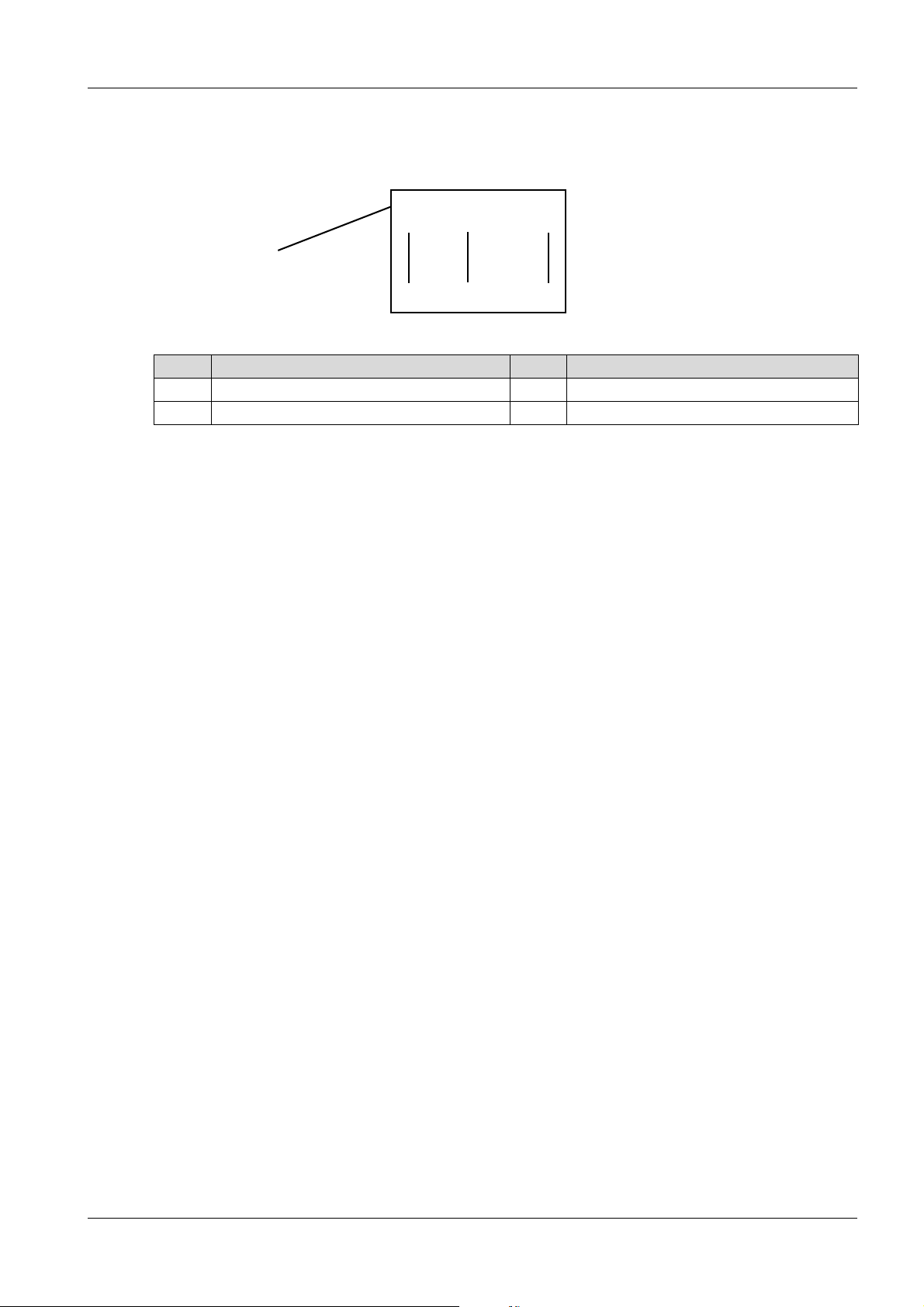
Error message.
1
2
3
Item Designation Item Designation
1 Consecutive number 3 Error code
2 Operating hours
1. In the diagnostics menu, select the erro r me m or y .
2. To select the stored error, repeatedly press the black setting button until the desired area appears.
3. To exit the error memory, press the red ON/OFF switch.
8.8 Operation of the configuration menu
The operation of the configuration menu is described in the manual for machine configuration.
8 Operation and use
100_0202_op_0011.fm 42
Page 43

9 Maintenance
9 Maintenance
WARNING
Improper handling can result in injury or serious material damage.
Please read and follow all safety instructions in this operator’s manual.
WARNING
Danger of poisoning by exhaust fumes.
Exhaust fumes contain poisonous carbon monoxide, which can lead to loss of
consciousness or death.
Maintenance jobs shall only be performed when the engine is switched off and the
WARNING
Risk of injury from uncontrolled running machine and moving parts.
Maintenance jobs shall only be performed when the engine is switched off and the
machine is decommissioned.
machine is decommissioned.
WARNING
Fire and explosion hazard from fuel and fuel vapors
Fuel and fuel vapors can ignite and cause serious burns.
Do not smoke.
Do not refuel near open flames.
Switch off engine and allow to cool before refueling.
WARNING
Warning of hot surfaces
The exhaust system and engine can become extremely hot, which can lead to severe skin
burns.
Always allow the engine to cool down completely after use.
If there is not enough time to allow the machine to cool down (e.g. in an emergency
situation.) – use heat-resistant protective gloves.
WARNING
Risk of injury from non-existent or non-functioning safety devices.
Only operate the machine if the safety devices are prop e rly fixed an d work ing .
Do not modify or remove safety devices.
9.1 Maintenance schedule – One-time maintenance job
The following maintenance jobs must only be performed after the first commissioning in
accordance with this interval.
Maintenance jobs After the first 50 hours
Replace engine oil and oil filter of the drive motor.
43 100_0202_mt_0011.fm
Page 44

9.2 Maintenance schedule – daily maintenance jobs
Maintenance jobs before operation after operation
Inspect for completeness.
Visual inspection for damage and leaks.
Check engine oil level and top up if necessary.
Check coolant level and top up if necessary.
Check radiator for dirt and clean if necessary.
Check air cleaner.
Clean machine and remote control.
9.3 Maintenance schedule – regular intervals
Maintenance jobs every 125 h every 250 h every 500 h
Make sure the screwed connections are firmly in place:
Crossbar
Central lifting point
Hydraulic oil tank
Rubber buffer of the base plate
9 Maintenance
Check exciter oil level.
Check hydraulic oil level.
Check hydraulic hose lines.*
Check hydraulic oil level on the center pole.
Check rubber buffer.*
Check function of the proximity recognition sensor (remote
control).
Check operation of the emergency shutdown switch.
Lubricate latches of the protective hood
Check central lifting point for damage.
Replace engine oil and oil filter of the drive motor.
Replace fuel filter.*
Check coolant hoses and clamps.*
Check anti-frost layer of radiator
Check the hosepipes and clamps of the air intake system.*
Replace air cleaner cartridge.
If the control lamp lights up, even before reaching the interval.
Replace exciter oil. *
Check the V-belt of the fan – tighten *.
Replace the hydraulic oil filter with air cleaner.*
Check tapped clearance and adjust if necessary. *
*
Have this work done by the service of Wacker Neuson.
100_0202_mt_0011.fm 44
Page 45
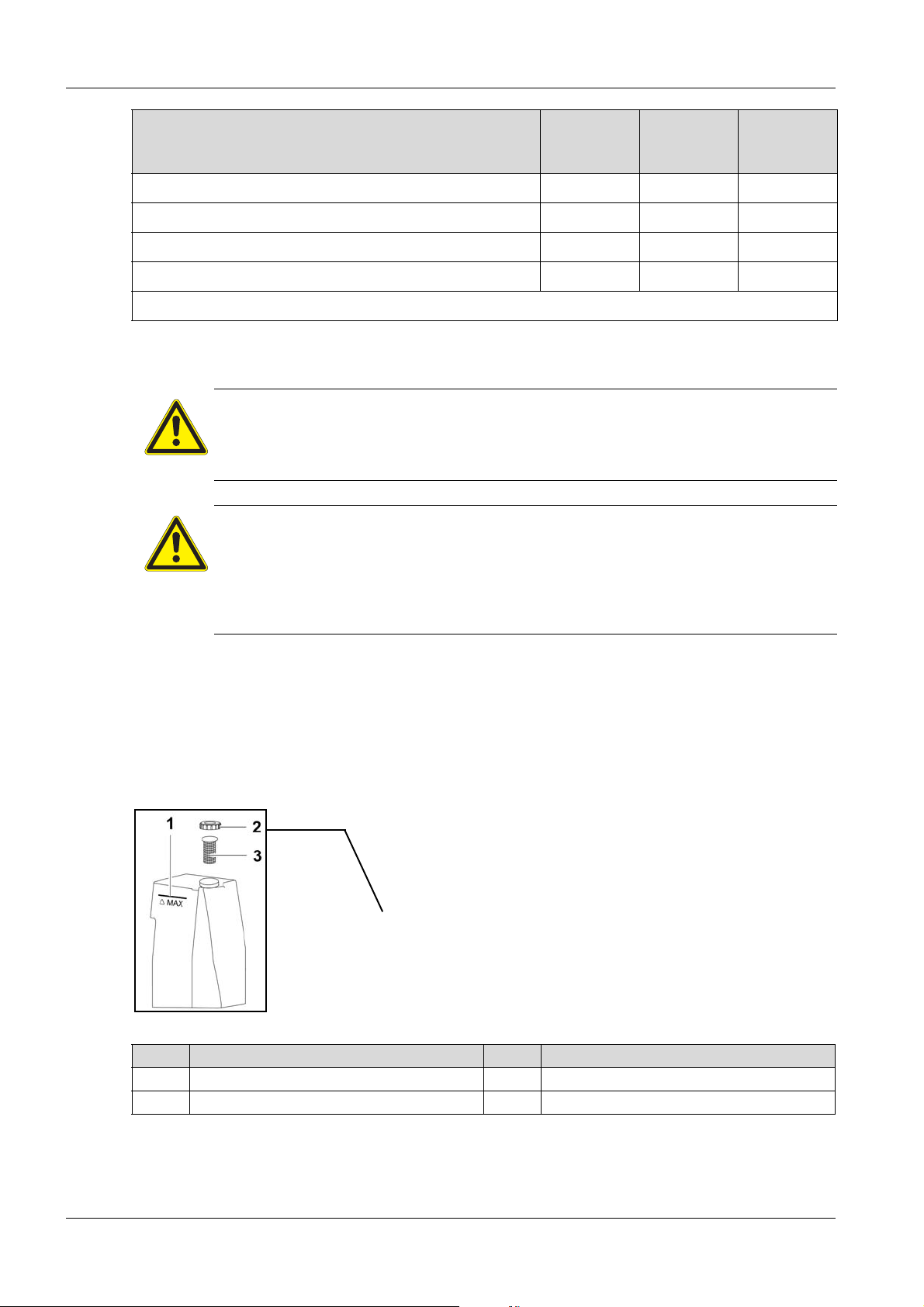
9 Maintenance
Maintenance jobs every 1000
Replace coolant.*
Replace the hydraulic oil.*
Replace the tooth belt pulley of the engine.*
Replace the hydraulic hose lines.*
*
Have this work done by the service of Wacker Neuson.
9.4 Maintenance jobs
CAUTION
Health hazard from fuel, lubricants and coolants
Do not inhale vapors from fuel, lubricants and coolants.
Avoid contact from fuel, lubricants and coolants with skin or eyes.
WARNING
Fire and explosion hazard from fuel and fuel vapors
Do not smoke.
Do not refuel near open flames.
Switch off engine and allow to cool before refueling. Only refuel in a well-ventilated
vicinity.
h/every 2
years
every 4000
h/every 4
years
every 6
years
Carry out preparations
1. Place the machine on a level surface.
2. Decommissioning the machine.
3. Deactivate machine.
4. Allow the engine to cool down.
9.4.1 Check the fuel level and top up if necessary
Item Designation Item Designation
1 Limit mark 3 Fuel filter
2 Fuel cap
1. Open rear protective hood.
2. Remove dirt accumulation in the area of the fuel cap.
3. Unscrew the fuel cap of the fuel tank and remove it.
45 100_0202_mt_0011.fm
Page 46
4. If necessary, remove and clean the dirty fuel filter. Reinsert fuel filter before topping up.
5. Add fuel to the limit mark – for fuel type, see Technical Data chapter.
6. Replace fuel cap and tighten.
7. Close rear protective hood.
NOTE
Dispose of impurities of the fuel filter in accordance with the applicable provisions for
environmental protection.
9.4.2 Clean machine and remote control
WARNING
Fire and explosion hazard when using flammable cleaning agents or solvents.
Do not clean machine, components, or operator's controls with gasoline or other
solvents.
NOTE
Permeating water can damage the engine, electrical operator's controls, or components
of the machine and remote control. Do not aim high-pressure washers directly at the air
intake and electrical components. Clean remote control with only a damp cloth.
9 Maintenance
1. After cleaning, check switches, levers, cables, hoses, pipes and hardware for leaks, loose
connections, abrasions and other da m ag e .
2. Immediately rectify any damage.
9.4.3 Check engine oil level and top up engine oil
Item Designation Item Designation
1 Cover of the oil filler opening 3 Label
2 O il-level dipstick
Check engine oil level
1. Open both protective hoods.
2. Remove dirt accumulation in the area of the oil-level dipstick.
3. Pull out oil-level dipstick.
4. Wipe oil-level dipstick with a dry, lint-free cloth.
5. Fully reinsert oil-level dipstick.
6. Pull out oil-level dipstick.
7. Check whether the oil is between the lower and upper mark of the oil-level dipstick.
100_0202_mt_0011.fm 46
Page 47

9 Maintenance
NOTE
The amount of oil between the upper and lower mark is between 0.6 l (DPU 80) and 1.0 l
(DPU 100).
Top up motor oil
1. Remove dirt accumulation in the area of the oil filler opening.
2. Remove cover of the oil filler opening.
3. If necessary, fill with engine oil until the upper mark of the oil-level dipstick is reached – for oil
specification, see Technical Data chapter.
4. Put the cover back on the oil filler opening and press firmly.
5. Wipe away any spilled oil.
NOTE
Dispose of oil in accordance with the applicable provisions for environmental protection.
9.4.4 Replace engine oil
NOTE
Change oil in lukewarm engine so that the oil can drain completely.
Item Designation Item Designation
1 Cover of th e oil filler opening 4 Oil filter
2 Oil-le vel dipstick 5 Oil drain plug
3 Label
Drain the engine oil and replace the oil filter
1. Open both protective hoods.
2. To protect the floor from leaking oil, cover the working surface with an impermeable foil.
3. Place a sufficiently large collecting container under the oil filter.
4. Unscrew and remove oil filter – when unscrewing, collect any leaking oil.
5. Place collecting container under the oil drain plug.
6. Loosen oil drain plug.
7. When the oil has completely drained, screw in the oil drain plug and tighten.
8. Screw in new oil filter and tighten by hand.
47 100_0202_mt_0011.fm
Page 48

NOTE
Dispose of oil in accordance with the applicable provisions for environmental protection.
Fill motor oil
1. Remove dirt accumulation in the area of the oil filler opening.
2. Remove cover of the oil filler opening.
3. If necessary, fill with oil until the upper mark of the oil-level dipstick is reached – for oil specification
and amount of oil, see Technical Data chapter.
4. Put the cover back on the oil filler opening and press firmly.
5. Wipe away any spilled oil.
6. Briefly allow the engine to run.
7. Switch off engine.
8. Check oil level and top up if necessary.
9.4.5 Check/clean/replace air cleaner
9 Maintenance
Item Designation Item Designation
1 Air cleaner 2 Dust discharge valve
1. Open rear protective hood.
Check air cleaner
Check whether the clamps of the air cleaner are tight and the air cleaner is undamaged.
Check whether the dust discharge valve is dirty. If necessary, squeeze dust discha rge valve to
remove the dirt.
Replace air cleaner cartridge
Item Designation Item Designation
1 Air cleaner cartridge 3 Clamps (2 pieces)
2 Lower housing part
100_0202_mt_0011.fm 48
Page 49
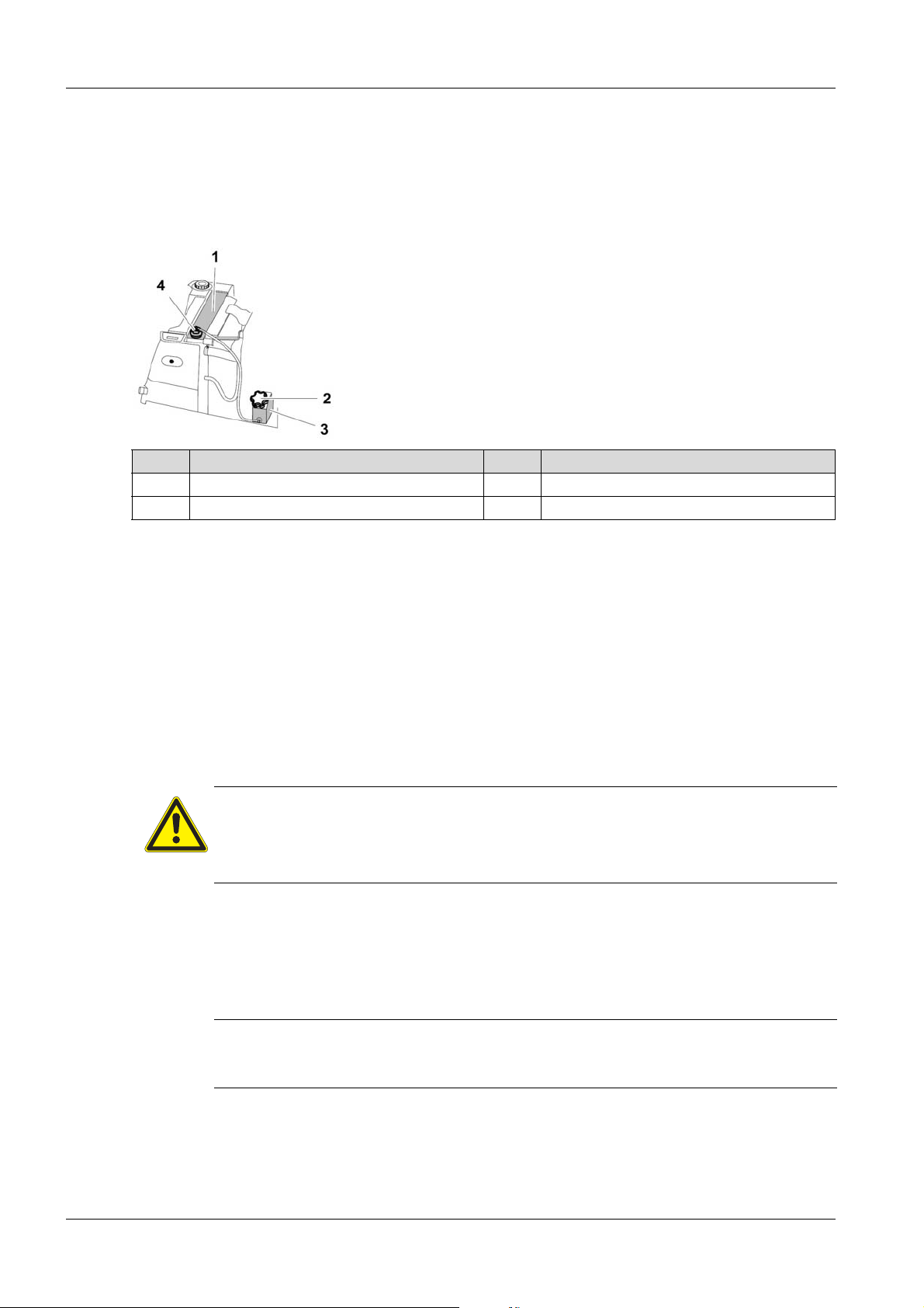
9 Maintenance
2. Loosen clamps and remove lower housing part.
3. Remove air cleaner cartridge.
4. Clean lower hou sin g pa rt .
5. Insert air cleaner cartridge.
6. Replace lower housing part and seal clamps.
9.4.6 Check the coolant level and top up coolant
Item Designation Item Designation
1 Radiator 3 Coolant reservoir
2 Cover of the coolant reservoir 4 Radiator cap
Check the coolant level in the coolant reservoir
1. Open both protective hoods.
2. Remove dirt accumulation in the area of the coolant reservoir.
3. Check that the coolant level is between the upper and mark of the coolant reservoir.
Top up coolant in the coolant reservoir
1. Unscrew and remove cover of the coolant reservoir.
2. If necessary, top up coolant until the coolant level is between the lower and upper mark – for coolant
specification, see Technical Data chapter.
3. Replace cover of the coolant reservoir and tighten.
Check the coolant level in the radiator
WARNING
The cooling system is under pressure.
Hot coolant can spurt out and cause injury from scalding.
Only open the cover of the radiator after the engine has cooled down .
1. Remove dirt accumulation in the area of the radiator cover.
2. Slowly unscrew the radiator cap and remove.
3. Check whether the coolant reaches the upper edge of the filler opening.
Top up coolant in the radiator
NOTE
If the machine is losing coolant, check the cooling system for leaks, and have the machine
repaired by the service of the Wacker Neuson contact person.
1. If necessary, top up coolant to the upper edge of the filler opening – for coolant specification, see
Technical Data chapter.
2. Replace ra dia to r ca p an d tig ht en .
49 100_0202_mt_0011.fm
Page 50
9.4.7 Check exciter oil level and top up exciter oil
Image in progress
Item Designation Item Designation
1 Screw plug with seal ring of the oil filler
opening
2 Screw plug with seal ring of the oil drain
opening
9 Maintenance
3 Level of exciter oil
Check exciter oil level
1. Open rear protective hood.
2. To protect the floor from leaking oil, cover the working surface with an impermeable foil.
NOTE
The machine has two exciters. Therefore, the level of exciter oil level must always be
checked for both exciters.
WARNING
Hot exciter oil can leak out and cause injury from scalding.
Do not open the screw plug of the exciter while the exciter oil is still hot.
Let the machine cool.
3. Remove dirt accumulation in the area of the screw plug.
4. Unscrew screw plug of the oil drain opening and remove together with the seal ring.
5. Check whether the level of exciter oil reaches the lower thread of the tapped bore.
Top up exciter oil
1. Unscrew screw plug of the oil filler opening and remove together with the seal ring.
2. Top up exciter up oil with a clean funnel at the oil filler opening until the exciter oil reaches the lower
thread of the oil drain opening – for oil specification, see Technical Data chapter.
3. Replace screw plug of the oil drain opening along with a new seal ring and tighten (torque setting of
100 Nm).
4. Replace screw plug of the oil filler opening along with a new seal ring and tighten (torque setting of
100 Nm).
5. Wipe away any spilled oil.
100_0202_mt_0011.fm 50
NOTE
Dispose of oil in accordance with the applicable provisions for environmental protection.
Page 51
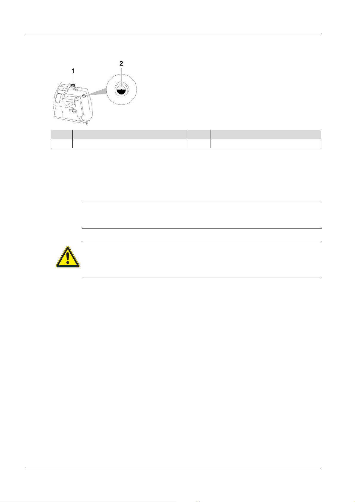
9 Maintenance
9.4.8 Check hydraulic oil level and top up hydraulic oil
Item Designation Item Designation
1 Cover of the hydraulic oil tank 2 Oil level glass
Check hydraulic oil level
1. Open both protective hoods.
2. Check whether the hydraulic oil reaches the upper edge of the oil level glass.
Top up hydraulic oil
NOTE
If the machine is losing hydraulic oil, check the hydraulic line for leaks, and have the
machine repaired by the service of the Wacker Neuson contact person.
WARNING
Hot hydraulic oil can cause injury by scalding.
Do not open the cover of the hydraulic oil tank while the hydraulic oil is still hot.
Let the machine cool.
3. Remove dirt accumulation in the area of the hydraulic oil tank.
4. Unscrew and remove cover of the hydraulic oil tank.
5. Top up hydraulic oil until the hydraulic oil reaches the middle of the oil level glass – for oil
specification, see Technical Data chapter.
6. Replace cover of the hydraulic tank and tighten (torque setting of 10 Nm) – make sure that the seal
of the cover fits properly.
9.4.9 Screwed connection
For the vibratory plates, the screwed connections must be regularly checked for tightness.
51 100_0202_mt_0011.fm
Page 52
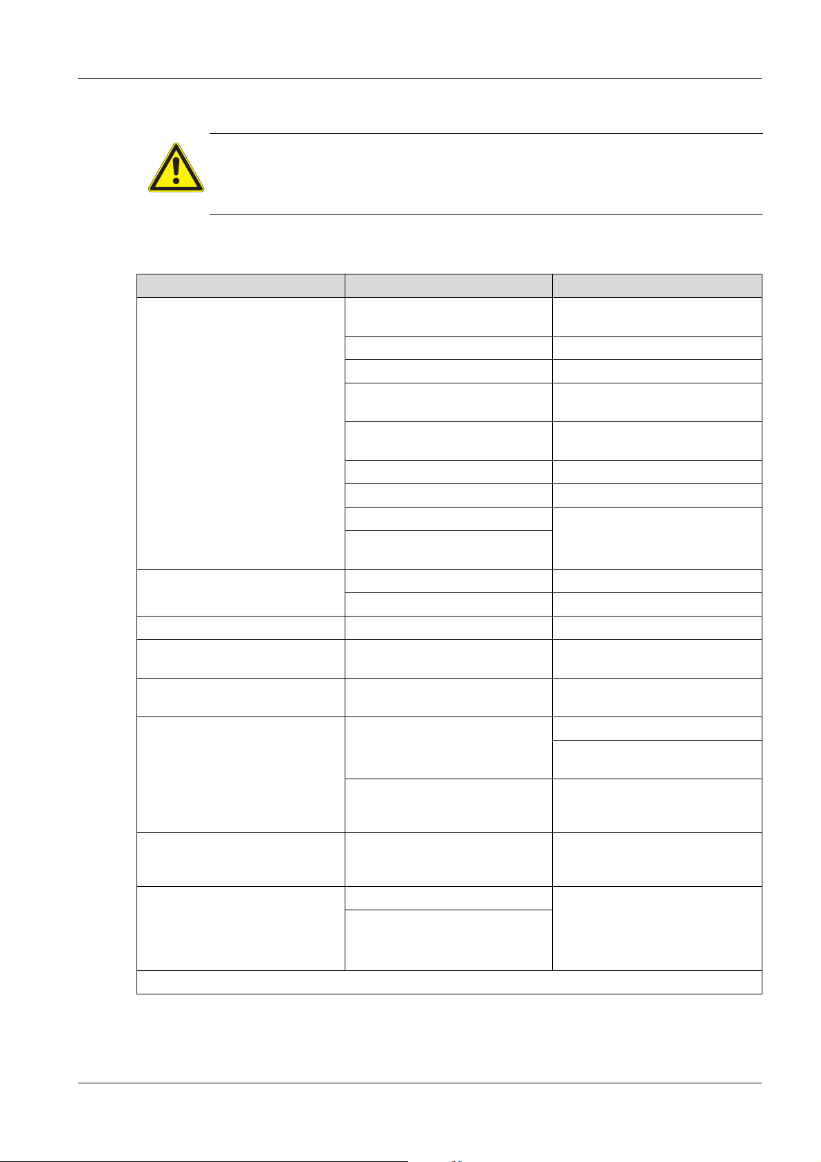
10 Troubleshooting
DANGER
Unauthorized troubleshooting can be life threatening.
In the case of any faults that do not appear in this manual, please contact the
manufacturer. Do not try to rectify them yourself.
10.1 Troubleshooting table – machine
Fault Possible causes Remedial measure
Motor will not start. Emergency shutdown switch is
pressed.
Air cleaner is dirty. Replace air cleaner.
Machine is not activated. Activate machine.
Discharge starter battery. Load starter battery or perform
Low oil level. Top up oil and actuate valve hood
Low fuel. Top up fuel.
Fuel filter is dirty. Replace fuel filter.*
10 Troubleshooting
Unlock emergency shutdown
switch.
jump-start with donor starter.
on the oil filter housing.
Defective starter motor. Have the machine repaired.*
Remote control, decoder, or wiring
harness is defective.
Engine runs unevenly. Fuel filter is dirty. Replace fuel filter.
Air cleaner is dirty. Clean or replace air cleaner.
Vibration will not start. Electrical system defective. Have the machine repaired.*
Engine smokes and does not
perform.
Another machine is controlled by
the remote control.
Machine cannot be deactivated. Incorrect activation PIN entered. Enter the correct activation PIN.
Diagnostics menu cannot be called
up.
Compatec - compaction display
(optional):
If all LEDs permanently flash after
initialization, the sensor has not
been successfully tested.
*
Have this work done by the service of Wacker Neuson.
Air cleaner is dirty. Replace air cleaner.
Both machines are set to the same
transmission channel.
Electrical system defective. 1. Deactivate machine with
ON/OFF switch of the machine not
pushed long and/or hard enough.
Switch-on with the engine running. Have the machine repaired.*
Sensor is defective.
Set one of the machines to a
different transmission channel.
Deactivate machine with
emergency shutdown switch.
emergency shutdown switch.
2. Have the machine repaired.*
Continuously press the ON/OFF
switch of machine for at least three
seconds.
100_0202_ts_0010.fm 52
Page 53

10 Troubleshooting
10.2 Troubleshooting table – receiving units
Fault Possible causes Remedial measure
Receiver units light up yellow.
Machine does not respond to
commands from the remote control.
Remote control is switched off. Switch on remote control unit.
Rechargeable battery of the
remote control is discharged.
Remote control is defective. Have remote control replaced or
Transmission channel of the
remote control has been incorrectly
set.
Operator is outside of the receiving
area.
Load or replace rechargeable
battery of the remote control.
repaired.*
Set the transmission channel.
Enter the receiving area of the
machine.
No clear line of sight between the
remote control and receiver unit.
Receiving units or remote control is
dirty.
Decoder, receiver unit, or electrical
Establish a clear line of sight with
the receiving unit.
Clean remote control and receiving
units.
Have the machine repaired.*
connection is defective.
Receiver units flash yellow in rapid
succession. Machine does not
Operator is located in the proximity
area.
Leave the proximity area of the
machine.
respond to commands from the
remote control.
Receiver units light up red. Machine is in the warm-up phase. Wait until the warm-up phase has
completed.
Diagnostic system has detected an
error.
Receiver units flash red. Machine is overloaded because
the soil cannot be compacted any
further.
Check control lamps and fault
indications on the display.
Avoid operation on non-
compactable soil.
Reduce compaction
performance through lower
deflection of the joystick of the
remote control.
Switching from fast to slow
operation.
*
Have this work done by the service of Wacker Neuson.
53 100_0202_ts_0010.fm
Page 54
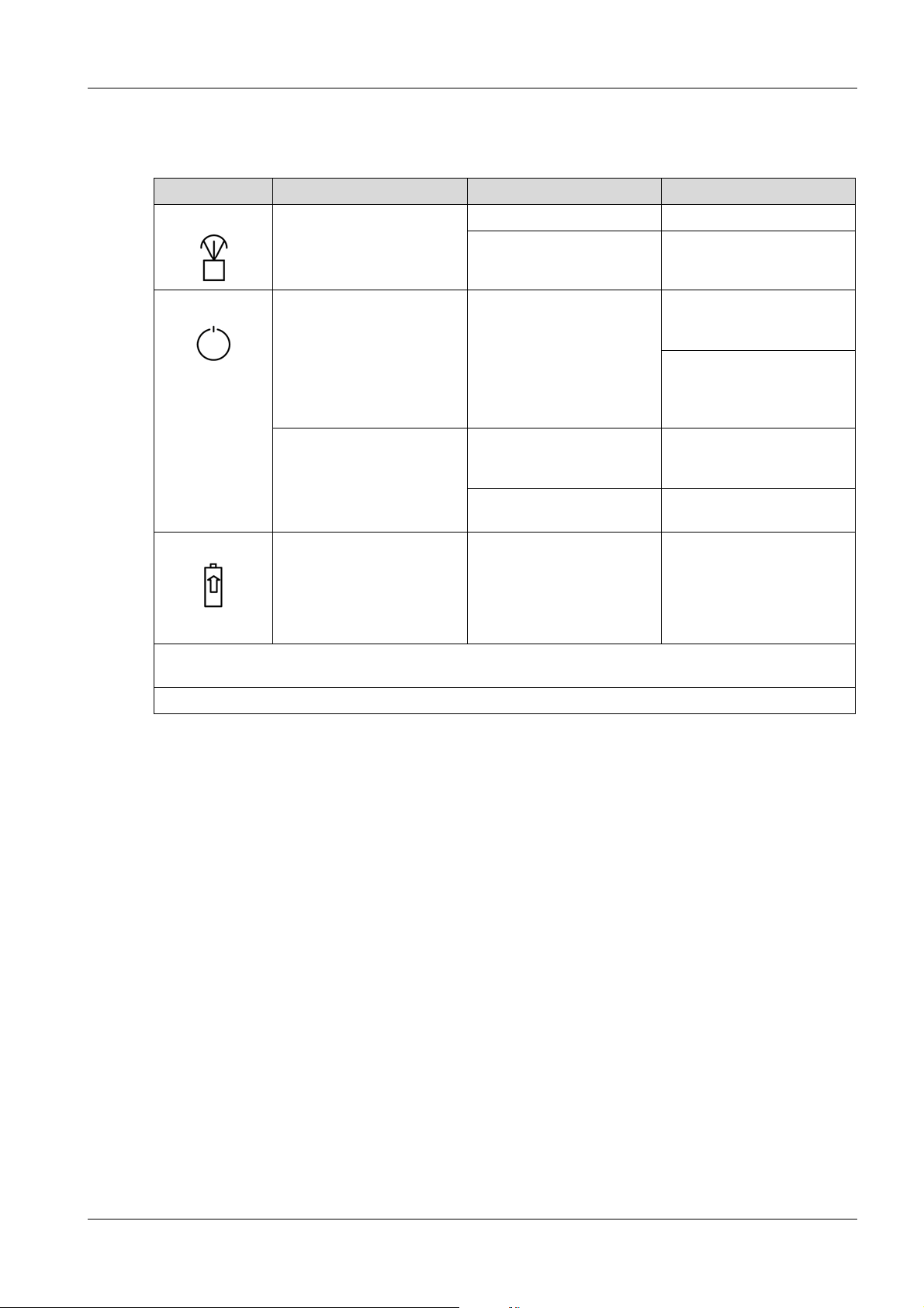
10.3 Troubleshooting chart – remote control
Pictogram LED under pictogram Possible causes Remedial measure
Control lamp lights red and
the diagnosis control lamp
flashes green.
Joystick is defective. Have joystick replaced. *
Remote control is defective. Have remote control
10 Troubleshooting
replaced or repaired. *
Control lamp flashes or lights
up red operation.
Rechargeable battery of the
remote control is discharged.
Load or replace
rechargeable battery of the
remote control.
Operate machine with
charging cable (for
simultaneous loading of the
rechargeable battery).
After switching on the
remote control, the operation
control lamp does not flash.
Rechargeable battery of the
remote control is discharged.
Load or replace
rechargeable battery of the
remote control.
Remote control is defective. Have remote control
replaced or repaired.*
Charging control lamp
flashes green.
The rechargeable battery is
automatically being prewarmed for charging.
Charging the battery at
temperatures below 0°C
Wait until the charging
control lamp is green and
charging begins.
Rechargeable battery at
temperatures above 0°C.
may not be possible.
Remote control switches itself off – if no button on the remote control is pressed, the remote control will
automatically switch off after 10 minutes.
*
Have this work done by the service of Wacker Neuson.
100_0202_ts_0010.fm 54
Page 55

10 Troubleshooting
10.4 Troubleshooting table – display
Pictogram LED under pictogram Possible causes Remedial measure
Control lamp for operation.
Charging control lamp lights
up red when the engine is
running.
Warm up control lamp lights
up yellow.
Air cleaner control lamp
lights up yellow.
Oil-pressure control lamp
lights up when the engine is
running.
Coolant-temperature control
lamp lights red.
*
Have this work done by the service of Wacker Neuson.
Error in the electric system. Have the machine repaired.*
Machine is in the startup
process.
Air cleaner cartridge is dirty. Replace air cleaner
Engine oil level is too low. Top up motor oil.
Oil pressure switch or
electrical connection is
defective.
Cooling fins of the cooler are
dirty.
Coolant level is too low. Top up coolant.
Cooling system is leaking. Have the machine repaired.*
Wait until the engine starts.
cartridge.
Have the machine repaired.*
Blow cooling fins with
compressed air from the
inside to the outside from a
safe distance.
Fault indications on the display
The last error is briefly displayed after each activation of the machine. If the error is corrected, the error
message should be acknowledged in the diagnostic menu because the error is no longer relevant for
further operation.
To acknowledge the last error, the diagnostic menu must be called up and exited. After the machine is
activated, the corrected error will no longer appear in the display.
55 100_0202_ts_0010.fm
Page 56

10 Troubleshooting
Error code Display Possible causes Remedial measure
1 Oil pressure
shutdown
Engine oil level is too low. 1. Deactivate machine.
2. Top up motor oil.
Oil pressure switch or electrical
Have the machine repaired.*
connection is defective.
2 Excess temperature
shutdown
Coolant level is too low. Top up coolant.
Cooling system is leaking. Have the machine repaired.*
Engine is overheated. Allow the engine to cool
down.
Cooling fins of the cooler are dirty. Blow cooling fins with
compressed air from the
inside to the outside from a
safe distance.
Temperature senso r is defective. Have the machine repaired.*
Fan wheel is broken.
V-belt of the fan wheel is defective or not
tight enough.
3 Overvoltage
shutdown
Charge controller or electrical
connection is defective.
4 Battery error Alternator, charge controller, battery, or
electrical connection is defective.
5 Charge controller/
generator shutdown.
Alternator, charge controller, or electrical
connection is defective.
6 Battery error Alternator, charge controller, battery, or
electrical connection is defective.
7 Check air cleaner Air cleaner cartridge is dirty. Replace air cleaner
cartridge.
Electrical connection of the air cleaner
sensor is defective.
Have the electrical
connection of the air cleaner
sensor checked.*
8 Air cleaner error Air cleaner sensor is defective. Have the machine repaired.*
Electrical connection of the air cleaner
sensor is defective.
Have the electrical
connection of the air cleaner
sensor checked.*
9 Oil pressure switch
shutdown
10 Charge controller
error
1 1 Charge controller/
generator error.
12 Overload shutdown Machine is overloaded because the soil
Oil pressure switch or electrical
connection is defective.
Charge controller or electrical
connection is defective.
Alternator, charge controller, or electrical
connection is defective.
cannot be compacted any further.
Have the machine repaired.*
Deactivate the machine and
then re-activate it.
To prevent overload, observe the following rules:
Avoid operation on non-compactable soil.
Reduce compaction performance through lower deflection of the
joystick of the remote control.
Switching from fast to slow operation.
100_0202_ts_0010.fm 56
Page 57

10 Troubleshooting
Error code Display Possible causes Remedial measure
13 Machine overloaded Machine is overloaded because the soil
Deactivate the machine and
cannot be compacted any further.
then re-activate it.
To prevent overload, observe the following rules:
Avoid operation on non-compactable soil.
Reduce compaction performance through lower deflection of the
joystick of the remote control.
Switching from fast to slow operation.
14 Overload sensor
shutdown
15 Address comparison
of IR transfer
16 Incorrect transmitter
unit for IR transfer
17 Incorrect address for
IR transfer
18 Allow the machine to
cool down.
19 Excess temperature
of the machine
Overload sensor or electrical connection
Have the machine repaired.*
is defective.
No fault. Transmission channel is
synchronized between remote control
and machine.
Incorrect model of remote control. Use correct model of remote
control.
Transmission channel on the remote
control has been incorrectly set.
Synchronize transmission
channel between remote
control and machine.
Coolant level is too low. Top up coolant.
Engine is overheated. Allow the engine to cool
down.
Cooling fins of the cooler are dirty. Blow cooling fins with
compressed air from the
inside to the outside from a
safe distance.
Cooling system is leaking. Have the machine repaired.*
Te mperature sensor is defective.
Coolant level is too low. Top up coolant.
Engine is overheated. Allow the engine to cool
down.
Cooling fins of the cooler are dirty. Blow cooling fins with
compressed air from the
inside to the outside.
Cooling system is leaking. Have the machine repaired.*
Te mperature sensor is defective.
20 Temperature sensor
error
Te mperature sensor or electrical
connection is defective.
At very low external temperatures, the
coolant does not reach the required
temperature of 55°C during the warm-up
phase. The machine will cancel the
warm-up phase but is ready for
operation.
21 Automatic start error Fuel tank is empty. Top up fuel.
Defect in fuel system.
Engine, diesel valve, or electrical
Have the machine repaired.*
connection of the diesel valve is
defective.
57 100_0202_ts_0010.fm
Page 58

10 Troubleshooting
Error code Display Possible causes Remedial measure
22 Charge controller/
start error.
23 Diesel valve error Diesel valve is defective.
24 Gas adjuster error Fuel tank is empty. Top up fuel.
25 Hydraulic
temperature sensor
error
26 Oil pressure
shutdown
Charge controller, starter motor, or
Have the machine repaired.*
electrical connection is defective.
Battery is discharged or defective. Charge or replace battery.
Have the machine repaired.*
Machine cannot be switched off.
Gas adjuster or electrical connection
Have the machine repaired.*
is defective.
Cable of the gas adjuster is defective.
80 A fuse has blown.
Hydraulic temperature sensor outside of
the valid range.
Engine oil level is too low. 1. Deactivate machine.
2. Top up motor oil.
Oil pressure switch or electrical
Have the machine repaired.*
connection is defective.
27 Overload sensor error Overload sensor or electrical connection
is defective.
28 IR receiver error Incorrect current value.
29 IR receiver error No power/not connected.
30 Error center pole unit No signal/not connected.
- Decoder error El ectrical connection in the electrical
box is defective.
*
Have this work done by the service of Wacker Neuson.
10.5 Perform jump start with donor starter battery
If the starter battery of the machine is discharged an d the engine does not start, a jump-start with a donor
battery is possible.
WARNING
Risk of explosion from explosive gas.
Risk of injury from splashing acid.
Wear safety glasses and protective gloves.
The donor battery and starter battery of the machine must have the same voltage (1 2 V)
Avoid short circuit from reverse polarity (plus to plus, minus to minus).
Use correct sequence when connecting the jumper cables.
1. Deactivate machine with
emergency shutdown
switch.
2. Have the machine
repaired.*
NOTE
Use only insulated jumper cables with a conductor cross-section of at least 16 mm².
100_0202_ts_0010.fm 58
Page 59

10 Troubleshooting
Item Designation Item Designation
1 Positive terminal of the discharged starter
battery
2 Negative terminal at the grounding point 5 Positive terminal of the donor starter battery
3 Black jumper cables 6 Red jumper cables
4 Negative terminal of the donor starter
battery
1. Connect clamping tongs of the red jumper cable to the positive terminal of the discharged starter
battery.
2. Connect clamping tongs of the red jumper cable to the positive terminal of the discharged donor
battery.
3. Connect clamping tongs of the black jumper cable to the negative terminal of the discharged donor
battery.
4. Reconnect second clamping tongs of the black jumper cable to a grounding point of the machine, e.g.
at the engine block.
Perform jump start
5. Start engine.
If the engine does not start after more than two minutes, inform your Wacker Neuson contact person.
6. Run engine for a few minutes.
Disconnect the jumper cable
7. Disconnect clamping tongs of the black jumper cable from the grounding point of the machine.
8. Disconnect second clamping tongs of the black jumper cable from the donor starter battery.
9. Disconnect clamping tongs of the red jumper cable from the positive terminal of the discharged starter
battery.
10.Disconnect clamping tongs of the red jumper cable from the positive terminal of the discharged donor
battery.
59 100_0202_ts_0010.fm
Page 60

11 Disposal
11.1 Disposal of batteries
For customers in EU countries
The unit contains one or more batteries or rechargeable batteries (hereinafter refe rr ed to as "th e
battery"). This battery is subject to the European Directive on (old) batteries (old) rechargeable batteries
and the respective national laws. The battery directive outlines the framewor k for an EU-wide treatment
of batteries.
The battery is marked with the following symbol of a crossed-out garbage bin. Below this
symbol, there is also the name of the pollutants contained i.e. "Pb" for lead, "Cd" for
cadmium, and "Hg" for mercury.
Batteries may not be disposed of with normal household waste. As end-user, you may
only dispose of used batteries via the manufacturer or specially equipped collection
facilities (statutory obligation to return); the delivery is free. Retailers and manufacturers are obliged to
take back these batteries and properly re cyc le th em or dispose of them of as hazardous waste (legal
obligation). Of course, after use, batteries purchased from us may also be retur ned free of charge. If you
do not personally return the batteries to on e of our offices, please en sure adequate postage. Please also
note any information in the sales contract or in the term s an d co nd itio ns of purch as e.
Proper disposal of the battery prevents negative effects on individuals and the environment, follows the
specific treatment of pollutants, and ensures the recycling of useful raw materials.
11 Disposal
For customers in other countries
The unit contains one or more batteries or rechargeable batteries (hereinafter refe rr ed to as "th e
battery"). Proper disposal of the battery prevents negative effects on individuals and the environment,
follows the specific treatment of pollutants, and ensures the recycling of useful raw materials. We
recommend that you do not dispose of the battery in normal household waste but rather in a separate
environmentally friendly collection facility. National laws may also have provisions for the separate
disposal of batteries. Please ensure that you safely dispose of your battery safely in accordance with
the applicable laws of your country.
100_0000_0007.fm 60
Page 61

12 Accessories
12 Accessories
CAUTION
Spare parts and accessories that do not originate from Wacker Neuson can increa se the
risk of injury and damage to the machine.
If other spare parts and accessories are used, Wacker Neuson shall not be held liable.
A wide range of accessories is offered for the machine.
More information about the individual accessories can be found online at www.wackerneuson.com.
Rechargeable battery
A replacement rechargeable battery is especially useful when the machine should be used for long
periods without interruption.
External battery charger
The external battery charger charges the rechargeable battery when it cannot be charged via the
charging cable of the machine.
The external battery charger has a country-specific plug to connection to various current networks.
61 100_0202_ac_0005.fm
Page 62

13 Technical data
13.1 DPU
Designation Unit DPU 80Le DPU100Le
Item number 5100018444 5100018445
Centrifugal force kN 80 100
Vibrations Hz 56.4 59.6
Compaction performance m
Travel speed* m/min
Reverse travel* m/min
Gradeability %
13 Technical data
RPM 3,380 3,580
2
/h
Length (center pole in
working position)
Width mm 670/770 870/970
Height mm 833 833
Operating weight kg
Under-clearance mm 833 833
Rated power kW 11.0 16.0
Nominal speed RPM 3,000 2,700
Coding possibilities - Maximum range of remote
control
Maximum transmission time
of remote control
Recommended battery type - Battery charging time h - Working pressure of
hydraulics
Maximum allowable hydraulic
pressure
mm 2,223 2,223
m- -
h- -
bar 165 193
bar 230 230
Coolant volume l 1.9 1.9
Type of coolant SAE J1034: water (1:1) SAE J1034: water (1:1)
Exciter oil quantity l 1.35 1.35
Type of exciter oil SAE 75W90 SAE 75W90
Hydraulic oil volume l 17.7 17.7
Type of hydraulic oil MR 520 MR 520
Storage temperature range °C −20 to +50 −20 to +50
Operating temperature range °C −10 to +50 −10 to +50
100_0202_td_0018.fm 62
Page 63

13 Technical data
Designation Unit DPU 80Le DPU100Le
Sound pressure level
At location of operation L
dB(A) 97 97
pA
Standard EN 500-4
Sound power level L
measured
guaranteed
wa
dB(A)
108
109
108
109
Standard EN 500-4, 2000/14/EG
Vibration total value a
hv
m/s
2
< 2.5 < 2.5
Standard EN 500-4
Uncertainty of measurement
of the vibration total value a
*
Dependent on soil conditions.
hv
m/s
2
0.5 0.5
Designation Unit DPU 80rLe DPU 100rLe
Item number 5100016604
Centrifugal force kN 80 100
Vibrations Hz 56.4 59.6
RPM 3,380 3,580
2
Compaction performance m
/h
Travel speed* m/min
Reverse travel* m/min
Gradeability %
Length (center pole in
mm 1,201 1,201
working position)
Width mm 670/770 870/970
Height mm 833 833
Operating weight kg
Under-clearance mm 833 833
Rated power kW 11.0 16.0
Nominal speed RPM 3,000 2,700
Coding possibilities - Maximum range of remote
m20 20
control
Maximum transmission time
h16 16
of remote control
Recommended battery type Ni-MH 7.2 V/2000 mAh Ni-MH 7.2 V/2000 mAh
Battery charging time h 2 2
Working pressure of
bar 165 193
hydraulics
63 100_0202_td_0018.fm
Page 64

13 Technical data
Designation Unit DPU 80rLe DPU 100rLe
Maximum allowable hydraulic
bar 230 230
pressure
Coolant volume l 1.9 1.9
Type of coolant SAE J1034: water (1:1) SAE J1034: water (1:1)
Exciter oil quantity l 1.35 1.35
Type of exciter oil SAE 75W90 SAE 75W90
Hydraulic oil volume l 17.7 17.7
Type of hydraulic oil MR 520 MR 520
Storage temperature range °C −20 to +50 −20 to +50
Operating temperature range °C −10 to +50 −10 to +50
Sound pressure level
At location of operation L
dB(A) 87 87
**
pA
Standard EN 500-4
Sound power level L
measured
guaranteed
wa
dB(A)
108
109
108
109
Standard EN 500-4, 2000/14/EG
Vibration total value a
hv
m/s
00
2
Standard EN 500-4
Uncertainty of measuremen t
of the vibration total value a
*
Dependent on soil conditions.
**
Measured at 5 m distance (remote controlled machine).
hv
m/s
2
--
100_0202_td_0018.fm 64
Page 65

13 Technical data
13.2 Combustion engine
Designation Unit DPU 80
Manufacturer Kohler
Type of engine KDW 702 KDW 1003
Combustion process Four-cycle Four-cycle
Cooling Water cooling Water cooling
Cylinders 2 2
Displacement cm³ 686 1,028
Maximum slanting position ° 25.0 25.0
Fuel type Diesel Diesel
Fuel consumption l/h 2.7 3.3
Tank capacity l 7.2 7.2
Oil specification SAE 10W40 SAE 10W40
Maximum oil filling l 1.6 2.4
Max. performance kW 11.5 18.5
RPM RPM 3,600 3,600
Standard DIN ISO 3046 IFN
DPU 100
Rated power kW 11.0 16.0
Nominal speed RPM 3,000 2,700
Standard DIN ISO 3046 IFN
Rated power output kW 9.6 12.0
Operating speed RPM 3,000 2,700
Standard DIN ISO 3046 IFN
Upper engine speed without
load
Air cleaner Dry-type air cleaner Dry-type air cleaner
Type of starter Electric starter Electric starter
Voltage of starter battery V 12 12
Battery capacity (nominal
value)
RPM 3,100 2,800
Ah 50
50
65 100_0202_td_0018.fm
Page 66

13.3 US combustion engine
13 Technical data
Designation Unit DPU 80 US
Manufacturer Kohler
Type of engine KDW 702 US KDW 1003 US
Combustion process Four-cycle Four-cycle
Cooling Water cooling Water cooling
Cylinders 2 2
Displacement cm³ 686 1,028
Maximum slanting position ° 25.0 25.0
Fuel type Diesel Diesel
Fuel consumption l/h 2.7 3.3
Tank capacity l 7.2 7.2
Oil specification SAE 10W40 SAE 10W40
Maximum oil filling l 1.6 2.4
Max. performance kW 11.5 18.5
RPM RPM 3,600 3,600
Standard DIN ISO 3046 IFN
DPU 100 US
Rated power kW 9.6 13.3
Nominal speed RPM 3,000 2,700
Standard DIN ISO 3046 IFN
Rated power output kW 9.6 12.0
Operating speed RPM 3,000 2,700
Standard DIN ISO 3046 IFN
Upper engine speed without
load
Air cleaner Dry-type air cleaner Dry-type air cleaner
Type of starter Electric starter Electric starter
Voltage of starter battery V 12 12
Battery capacity (nominal
value)
RPM 3,100 2,800
Ah 50
50
100_0202_td_0018.fm 66
Page 67

14 Emission control systems information and warranty
14 Emission control systems information and warranty
The Emission Control Warranty and associated information is valid only for the U.S.A., its territories, and
Canada.
Emission control systems warranty statement
See the engine owner’s manual for the applicable exhaust and evaporative emission warranty
statement.
67 100_0000_0020.fm
Page 68

EC Declaration of conformity
Helmut Bauer
Managing Director
Munich, 01.06.2015
Manufacturer
Wacker Neuson Produktion GmbH & Co. KG, Preussenstrasse 41, 80809 Munich
Product
Product DPU 80Le DPU 100Le
Product type Vibratory plate
Function of product Soil compaction
Item number 5100018444 5100018445
Net installed power 11.0 kW 16.0 kW
Measured sound power level 108 dB(A) 108 dB(A)
Guaranteed sound power level 109 dB(A) 109 dB(A)
Conformity assessment procedure
In accordance with 2000/14/EG, Appendix VIII, 2005/88/EC.
Agency
VDE Prüf- und Zertifizierungsinstitut GmbH, Merianstraße 28 , 63069 Offenbach/Main
Guidelines and standards
We hereby declare that this product complies with the requirements of the following guideline and standards:
2006/42/EC, 2000/14/EC, 2005/88/EC
Person responsible for technical documents
Leo Göschka
Wacker Neuson Produktion GmbH & Co. KG, Preussenstrasse 41, 80809 Munich
Translation of the original Declaration of Conformity
Page 69
EC Declaration of conformity
Helmut Bauer
Managing Director
Munich, 01.06.2015
Manufacturer
Wacker Neuson Produktion GmbH & Co. KG, Preussenstrasse 41, 80809 Munich
Product
Product DPU 80rLe DPU 100rLe
Product type Vibratory plate
Function of product Soil compaction
Item number 5100016604
Net installed power 11.0 kW 16.0 kW
Measured sound power level 108 dB(A) 108 dB(A)
Guaranteed sound power level 109 dB(A) 109 dB(A)
Conformity assessment procedure
In accordance with 2000/14/EG, Appendix VIII, 2005/88/EC.
Agency
VDE Prüf- und Zertifizierungsinstitut GmbH, Merianstraße 28 , 63069 Offenbach/Main
Guidelines and standards
We hereby declare that this product complies with the requirements of the following guideline and standards:
2006/42/EC, 2000/14/EC, 2005/88/EC, 2004/108/EC, EN13309:2000
Person responsible for technical documents
Leo Göschka
Wacker Neuson Produktion GmbH & Co. KG, Preussenstrasse 41, 80809 Munich
Translation of the original Declaration of Conformity
Page 70

Page 71

Page 72

 Loading...