

Wacker Neuson CUB 200, CUB 300 Repair Manual
Repair Manual
Indirect-Fired Air Heater
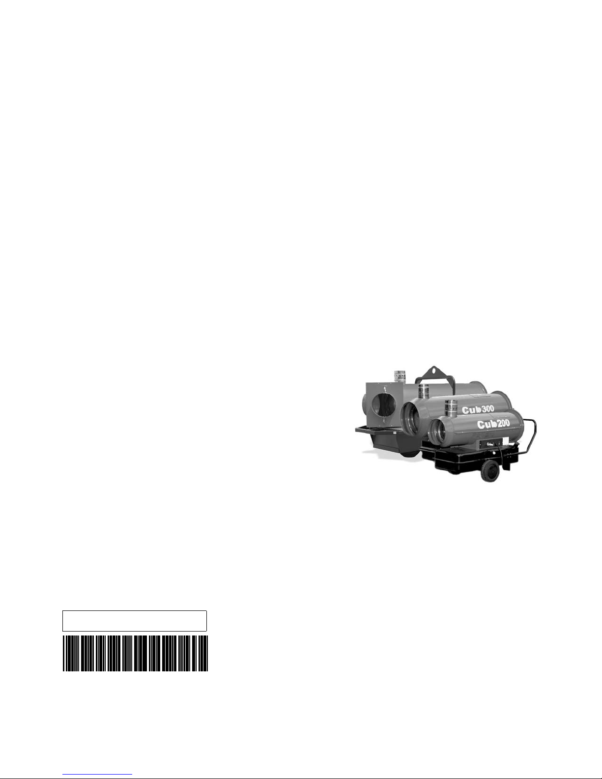
Cub 200
Cub 300
0179422en 001 1009
0179422EN

Copyright
notice
© Copyright 2009 by Wacker Neuson Corporation.
All rights, including copying and distribution rights, are reserved.
This publication may be photocopied by the original purchaser of the machine. Any
other type of reproduction is prohibited without express written permission from
Wacker Neuson Corporation.
Any type of reproduction or distribution not authorized by W acker Neuson Corp oration
represents an infringement of valid copyrights. Violators will be prosecuted.
T ra d emarks
Manufacturer
All trademarks referenced in this manual are the property of their respective owners.
Wacker Neuson Corporation
N92W15000 Anthony Avenue
Menomonee Falls, WI 53051 U.S.A.
Tel: (262) 255-0500 · Fax: (262) 255-0550 · Tel: (800) 770-0957
www.wackerneuson.com

Cub 200/300 Foreword
Foreword
Machines
covered by
this manual
Machine Item Number Machine Item Number
Cub 200 0620204 Cub 300 0620233
Cub 200 0620262 — —
Machine
documentation
Expectations
for
information in
this manual
Manufacturer’s
approval
Keep a copy of the Operator’s Manual with the machine at all times.
Use the separate Parts Book supplied with the machine to order replacement
parts.
If you are missing any of these documents, please contact Wacker Neuson
Corporation to order a replacement or visit www.wackerneuson.com.
When ordering parts or requesting service information, be prepared to provide
the machine model number, item number, revision number, and serial number.
This manual provides information and procedures to safely operate and
maintain the above Wacker Neuson model(s). For your own safety and to
reduce the risk of injury, carefully read, understand, and obse rve a ll instructions
described in this manual.
Wacker Neuson Corporation expressly reserves the right to make technical
modifications, even without notice, which improve the performance or safety
standards of its machines.
The information contained in this manual is based on machines manufactured
up until the time of publication. Wacker Neuson Co rporation reserves the right to
change any portion of this information without notice.
This manual contains several references to approved parts, att achment s, and mod-
ifications. The following definitions apply:
Approved parts or attachments are those either manufactured or provided by
Wacker Neuson.
Approved modifications are those performed by an authorized Wacker Neu-
son service center according to written instructions published by Wacker Neuson.
Unapproved parts, attachments, and modifications are those that do not
meet the approved criteria.
Unapproved parts, attachments, or modifications may have the following consequences:
Serious injury hazards to the operator and persons in the work area
Permanent damage to the machine which will not be covered under warranty
Contact your Wacker Neuson dealer immediately if you have questions about
approved or unapproved parts, attachments, or modifications.
ghi_tx001204gb.fm 3

Foreword Cub 200/300
ghi_tx001204gb.fm 4

Cub 200/300 Table of Contents
1 Safety Information 7
1.1 Signal Words Found in this Manual ...................................................... 7
1.2 Safety Guidelines for Operating the Machine ....................................... 8
1.3 Safety Guidelines for Lifting the Machine ............................................. 9
1.4 Safety Guidelines While Using Combustion Burners ......................... 10
1.5 Safety Guidelines for Maintaining the Machine .................................. 11
2 Operation 12
2.1 Controls and Components .................................................................. 12
2.2 Control Panel ...................................................................................... 13
2.3 Starting/Stopping the Machine ........................................................... 14
3 Burner Setup 16
3.1 Control Board Sequence of Operation ............................................... 16
3.2 Setting Up the Burner ......................................................................... 18
3.3 Removing and Installing the Burner Assembly ................................... 21
3.4 Checking and Adjusting the Burner Electrodes .................................. 22
3.5 Checking and Replacing the Burner Nozzle ....................................... 23
3.6 Setting the Air Band ........................................................................... 24
3.7 Checking and Adjusting the Fuel Pressure ........................................ 25
4 Troubleshooting Basics 27
5 Troubleshooting the Blower 28
5.1 Checking the Fuse ............................................................................. 29
5.2 Checking Power to/from the Control Board ........................................ 31
5.3 Checking the ON-OFF Switch ............................................................ 33
5.4 Checking the Capacitor ...................................................................... 35
5

Table of Contents Cub 200/300
6 Troubleshooting the Burner 37
6.1 Checking the Ignition Transformer ......................................................39
6.2 Checking the Cad Cell .........................................................................42
6.3 Checking the Fuel Filter Heater ...........................................................44
6.4 Checking Output Voltage from the Control Board ...............................46
6.5 Checking the Air Pressure Switch .......................................................48
6.6 Checking the Fuel Solenoid ................................................................51
6.7 Checking the Flame Head ...................................................................54
6.8 Checking the Fuel Flow from the Nozzle .............................................55
6.9 Checking the Fuel Lines ......................................................................57
6.10 Checking the Fuel Pump Adapter .......................................................58
7 Schematic 59
7.1 Cub 200/Cub 300 Schematic ..............................................................59
ghi_br0179422en_001TOC.fm 6
Cub 200/300 Safety Information
1 Safety Information
1.1 Signal Words Found in this Manual
This is the safety alert symbol. It is used to alert you to potential personal hazards.
f Obey all safety messages that follow this symbol.
DANGER
DANGER indicates a hazardous situation which, if not avoided, will result in death
or serious injury.
f To avoid death or serious injury from this type of hazard, obey all safety mes-
sages that follow this signal word.
WARNING
WARNING indicates a hazardous situation which, if not avoided, could result in
death or serious injury.
f To avoid possible death or serious injury from this type of hazard, obey all safety
messages that follow this signal word.
CAUTION
CAUTION indicates a hazardous situation which, if not avoided, could result in
minor or moderate injury.
f To avoid possible minor or moderate injury from this type of hazard, obey all
safety messages that follow this signal word.
NOTICE: Used without the safety alert symbol, NOTICE indicates a situation
which, if not avoided, could result in property damage.
Note: A Note contains additional information important to a procedure.
ghi_si000343gb.fm 7

Safety Information Cub 200/300
1.2 Safety Guidelines for Operating the Machine
Operator
training
Machine
condition
Before operating the machine:
Read and understand the operating instructions contained in all manuals
delivered with the machine.
Familiarize yourself with the location and proper use of all controls and safety
devices.
Contact Wacker Neuson Corporation for additional training if necessary.
When operating this machine:
Do not allow improperly trained people to operate the machine. People
operating the machine must be familiar with the potential risks and hazards
associated with it.
Only operate the machine when:
All safety devices and guards are in place and in working order.
All controls operate correctly.
The machine is set up correctly according to the instructions in the Operator’s
Manual.
The machine is clean.
The machine’s labels are legible.
When operating the machine:
Do not modify or defeat the safety devices.
Do not use worn electrical cords.
Do not use faulty fuel supplies.
Guidelines for
operator
Work space
When operating the machine:
Remain aware of the machine’s moving parts. Keep hands, feet, and loose
clothing away from the machine’s moving parts.
Wear protective clothing appropriate to the job site when operating the machine.
Wear safety glasses.
When operating the machine:
Do not operate a machine in need of repair.
Do not smoke near the machine.
When operating the machine:
Position the machine on a firm, noncombustible, level surface.
Keep the area immediately surrounding and underneath the machine clean,
neat, and free of debris and combustible materials.
Keep the area above the machine clear of debris that could fall on the machine.
Store the machine properly when it is not being used.
Keep unauthorized personnel, children, and pets away from the machine.
8 ghi_si000343gb.fm

Cub 200/300 Safety Information
When operating the machine:
Do not connect ductwork between the exhaust outlet port and the supply air inlet
port.
Never operate the machine in areas that contain flammable objects, fuels, or
products that produce flammable vapors.
Do not position the electrical cords under the machine or over the top of the
machine.
1.3 Safety Guidelines for Lifting the Machine
Lifting/
transporting
the machine
When lifting/transporting the machine:
Make sure all lifting devices are attached securely and have enough weight-
bearing capacity to lift or hold the machine safely.
Remain aware of the location of other people when lifting the machine.
Only use the lifting points and tie-downs described in the Operator’s Manual.
Only use suitable transport vehicles with sufficient load-carrying capacity.
When lifting the machine:
Never walk or stand under a suspended machine.
Never climb, sit, or stand on the machine while lifting it or transporting it.
ghi_si000343gb.fm 9

Safety Information Cub 200/300
1.4 Safety Guidelines While Using Combustion Burners
When using the machine:
Clean up any spilled fuel immediately.
Replace the fuel tank cap after refueling the machine.
Refill the fuel tank in a well-ventilated area.
Shut down the generator, if equipped, when refueling.
When using the machine:
DANGER
Exhaust gas from the burner contains carbon monoxide, a deadly poison. Exposure
to carbon monoxide can kill you in minutes.
f Never run the machine indoors or in an enclosed area unless the machine is
vented properly.
Do not fill or drain the fuel tank near an open flame or while the machine is
running.
Do not smoke when refueling the machine.
10 ghi_si000343gb.fm

Cub 200/300 Safety Information
1.5 Safety Guidelines for Maintaining the Machine
Training
Cleaning
Maintenance
guidelines
Only trained personnel should troubleshoot or repair electrical problems occur-
ring with the machine.
When cleaning and servicing the machine:
Keep the area around the burner free of debris such as leaves, paper, cartons,
etc.
Keep the machine clean and labels legible.
When cleaning the machine:
Do not clean the machine while it is running.
Never use gasoline or other types of fuels or flammable solvents to clean parts.
Fumes from fuels and solvents can become explosive.
When maintaining the machine:
Keep the fuel lines in good condition and properly connected.
Allow the burner to cool before maintaining the machine.
Reinstall the safety devices and guards after repairs and maintenance.
Keep all electrical cords away from heat, oil, vibrating surfaces, and sharp
edges.
Inspect all electrical cords before each use and replace damaged cords.
Replacing
parts and
labels
Accessories,
safety devices
and
modifications
When maintaining the machine:
Replace worn or damaged components.
Use only spare parts recommended by Wacker Neuson Corporation.
Replace all missing and hard-to-read labels.
Replace or repair electrical components with components that are identical in
rating and performance as the original component.
When using the machine:
Use only accessories/attachments that are recommended by Wacker Neuson
Corporation.
When using the machine:
Never operate the machine if any safety devices or guards are missing or inop-
erative.
Do not defeat safety devices.
Do not modify the machine without the express written approval of the manufac-
turer.
ghi_si000343gb.fm 11
Operation Cub 200/300
2 Operation
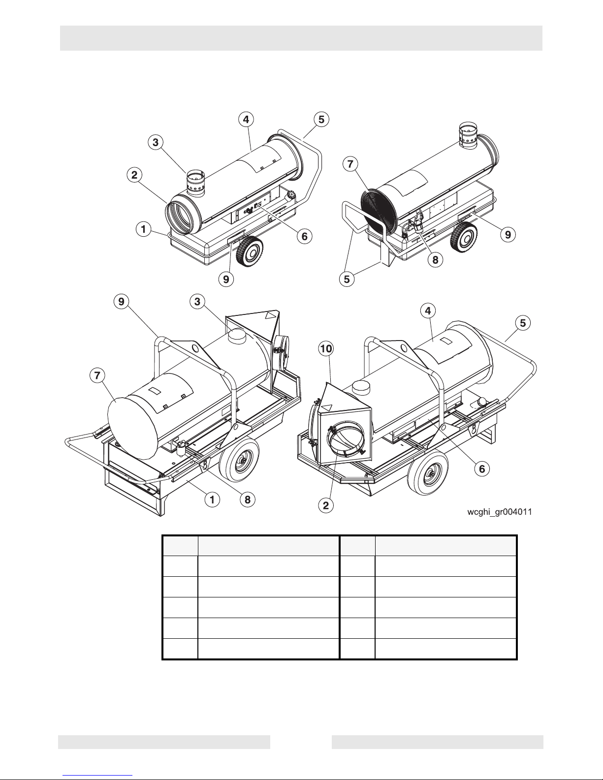
2.1 Controls and Components
Ref Component Ref Component
1 Fuel tank 2 Air outlet
3 Flue collar (vent) 4 Burner access panel
5 Handle (and base) 6 Control panel
7 Blower 8 Fuel oil filter
9 Lifting device 10 Duct adapter
ghi_tx001205gb.fm 12
Cub 200/300 Operation
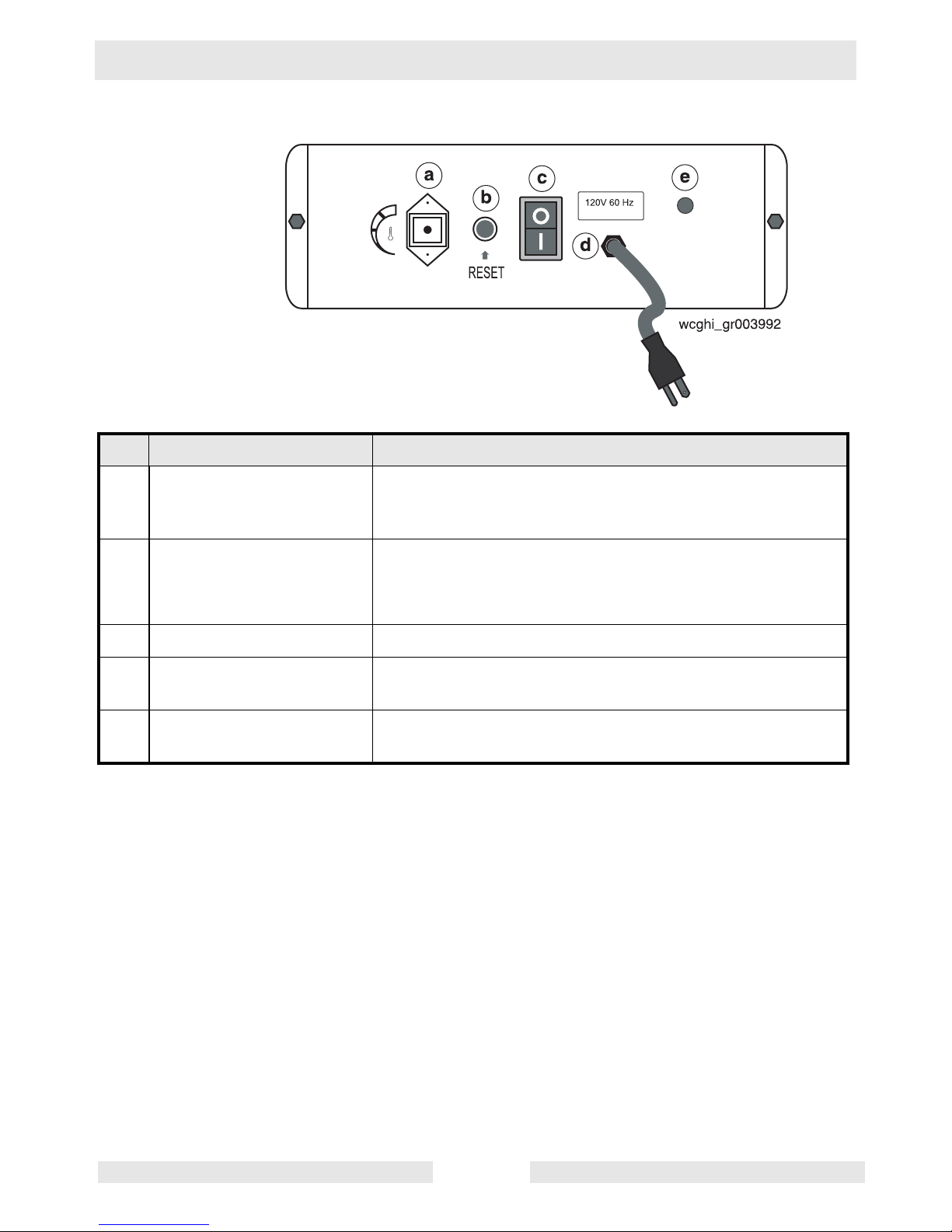
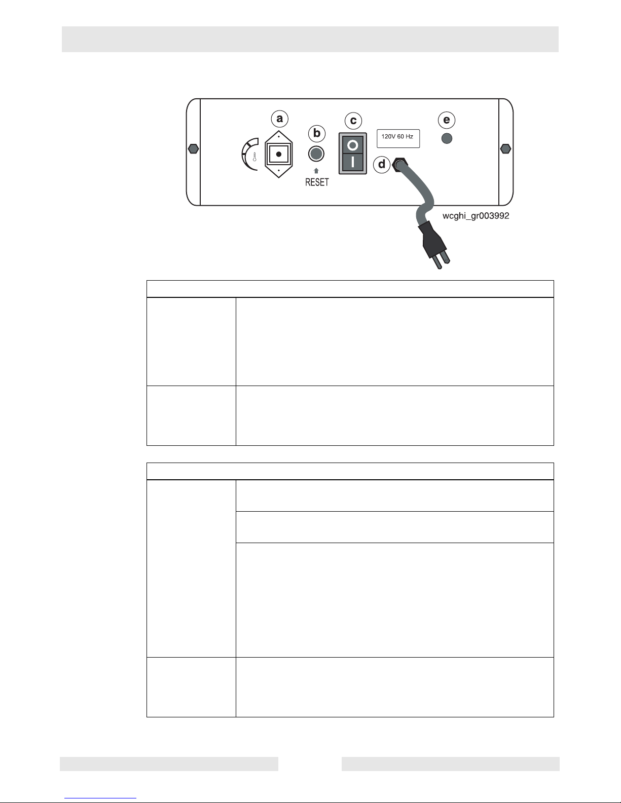
2.2 Control Panel
Ref Component Function
a Remote thermostat
receptacle
The remote thermostat receptacle (shown with protective
cap installed) is used for connecting an optional remote
thermostat.
b Burner fault lamp and reset
button (dual function)
The dual function burner fault lamp and reset button:
• illuminates red when the burner has faulted.
• resets the machine when pressed.
c Power switch The power switch provides power to the machine.
d Power cord The power cord provides a means of connecting the
machine to a 115V 60 Hz receptacle.
e Power indicator lamp The power indicator lamp illuminates green when the power
cord is connected to a 115V 60 Hz receptacle.
ghi_tx001205gb.fm 13
Operation Cub 200/300
2.3 Starting/Stopping the Machine
If not using the remote thermostat
Turning ON
Turning OFF
1. Move the power switch (c) to the ON “I” position.
The blower will turn on immediately.
The burner will go through a prepurge cycle and then
ignite.
The burner will continue to fire and the blower will con-
tinue to operate until the machine is turned off.
2. Move the power switch to the OFF position.
The burner will shut down.
The blower will continue to operate for approximately
two minutes to allow the combustion chamber to cool.
If using the remote thermostat
Turning ON
1. Connect the remote thermostat to the control panel at the
remote thermostat receptacle (a).
2. Place the remote thermostat in the area to be heated. Set it
to the desired temperature.
3. Move the power switch (c) to the ON “I” position.
The blower will turn on immediately.
The burner will go through a prepurge cycle and then
light.
The burner will continue to fire until the temperature of
the space being heated reaches the temperature set by
the thermostat. At that time, the burner shuts down but
the blower will remain on.
Turning OFF
4. Move the power switch to the OFF position.
The burner will shut down.
The blower will continue to operate for approximately
two minutes to allow the combustion chamber to cool.
ghi_tx001205gb.fm 14

Cub 200/300 Operation
Notes
ghi_tx001205gb.fm 15
Burner Setup Cub 200/300
3 Burner Setup
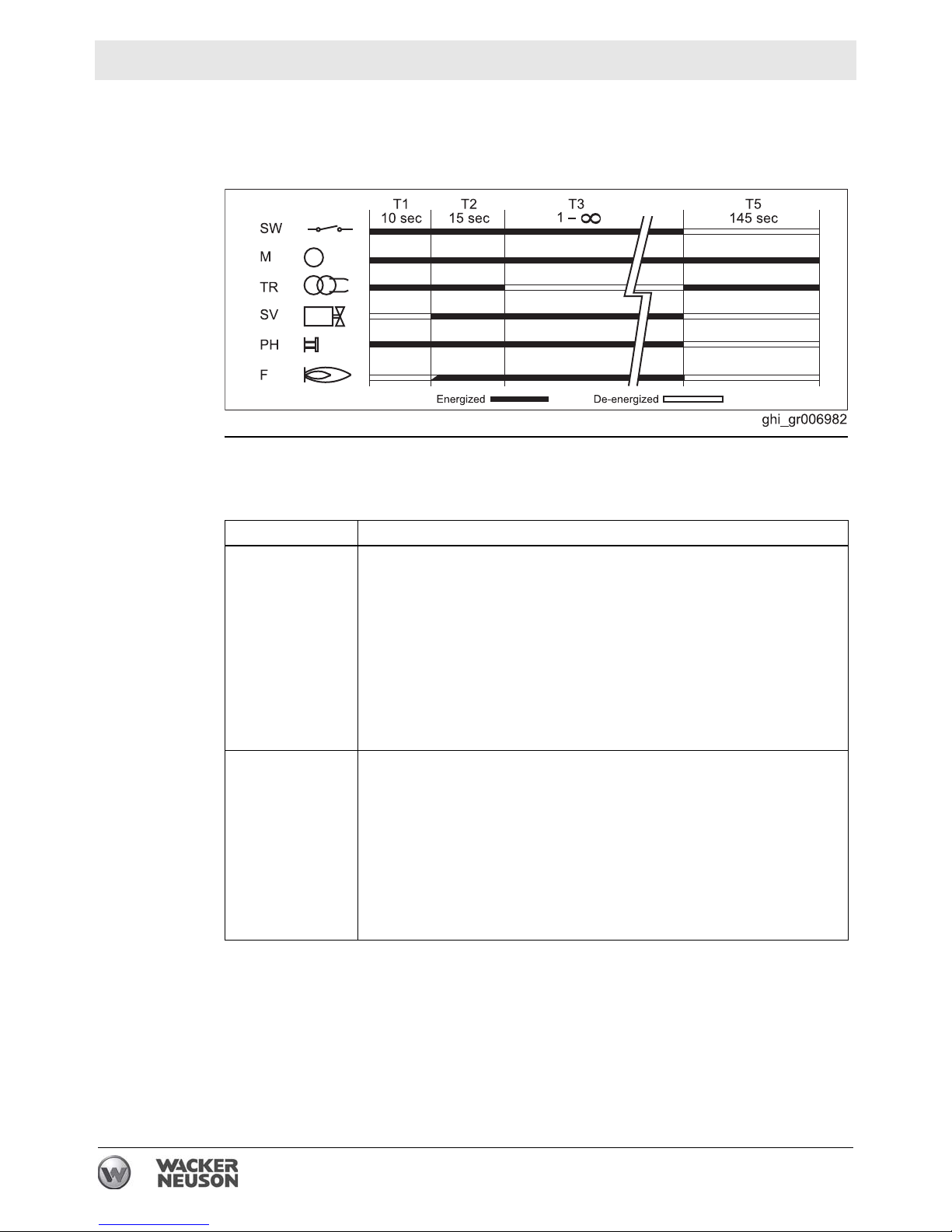
3.1 Control Board Sequence of Operation
Periods
The burner controller has several periods it sequences through during normal
operation. These periods are described below.
.
Period Action or Function
Prepurge (T1) As soon as the control switch (SW) is turned ON, the prepurge period
begins. It lasts approximately 10 seconds.
During this period:
The fan blows air into the combustion chamber to expel any resid-
ual exhaust gases.
The ignition transformer (TR) turns ON and remains ON. It pro-
duces a continuous spark across the electrodes so that any residual fuel is ignited and burned off.
The flame control unit (cad cell) (PH) checks for presence of a
flame. If a consistent flame is detected, the ignition sequence is
interrupted and the heater locks out.
Ignition (T2) After the prepurge period, the ignition period begins. It lasts
approximately 15 seconds.
During this period:
The fan runs .
The ignition transformer (TR) is ON, producing a continuous spark
across the electrodes.
The fuel solenoid (SV) opens and the fuel is ignited. The fuel sole-
noid will remain open if the cad cell (PH) detects a flame within 1
second from the start of this period. If no flame is detected, the fuel
solenoid closes and the heater locks out.
16 ghi_tx001317gb.fm

Cub 200/300 Burner Setup
Period Action or Function
Operation (T3) After the ignition period, the operation period begins. It will last as
long as there is flame or until the heater is turned off.
During this period:
The fan runs.
The ignition transformer (TR) is OFF. There is no spark across the
electrodes.
The fuel solenoid (SV) is open and flame is self-sustaining. The
cad cell (PH) monitors the flame. If the flame is interrupted through
lack of fuel or lack of air, the machine will go through the prepurge
and ignition period in an attempt to re-establish the flame. If the
flame is not re-established, the aftercooling period begins.
Aftercooling (T5) After the heater is turned OFF (or af ter flame re-establishment has
failed), the aftercooling period begins. It last s appro ximately 1 minute
and 45 seconds.
During this period:
The power switch is OFF .
The fan runs. After approximately 1 minute and 45 seconds, the
fan stops.
The ignition transformer (TR) turns ON and remains ON. It pro-
duces a continuous spark across the electrodes so that any residual fuel is ignited and burned off.
Reset To reset the heater:
1. Wait 30 seconds after the lockout condition has occurred.
2. Push th e reset button.
ghi_tx001317gb.fm 17
Burner Setup Cub 200/300
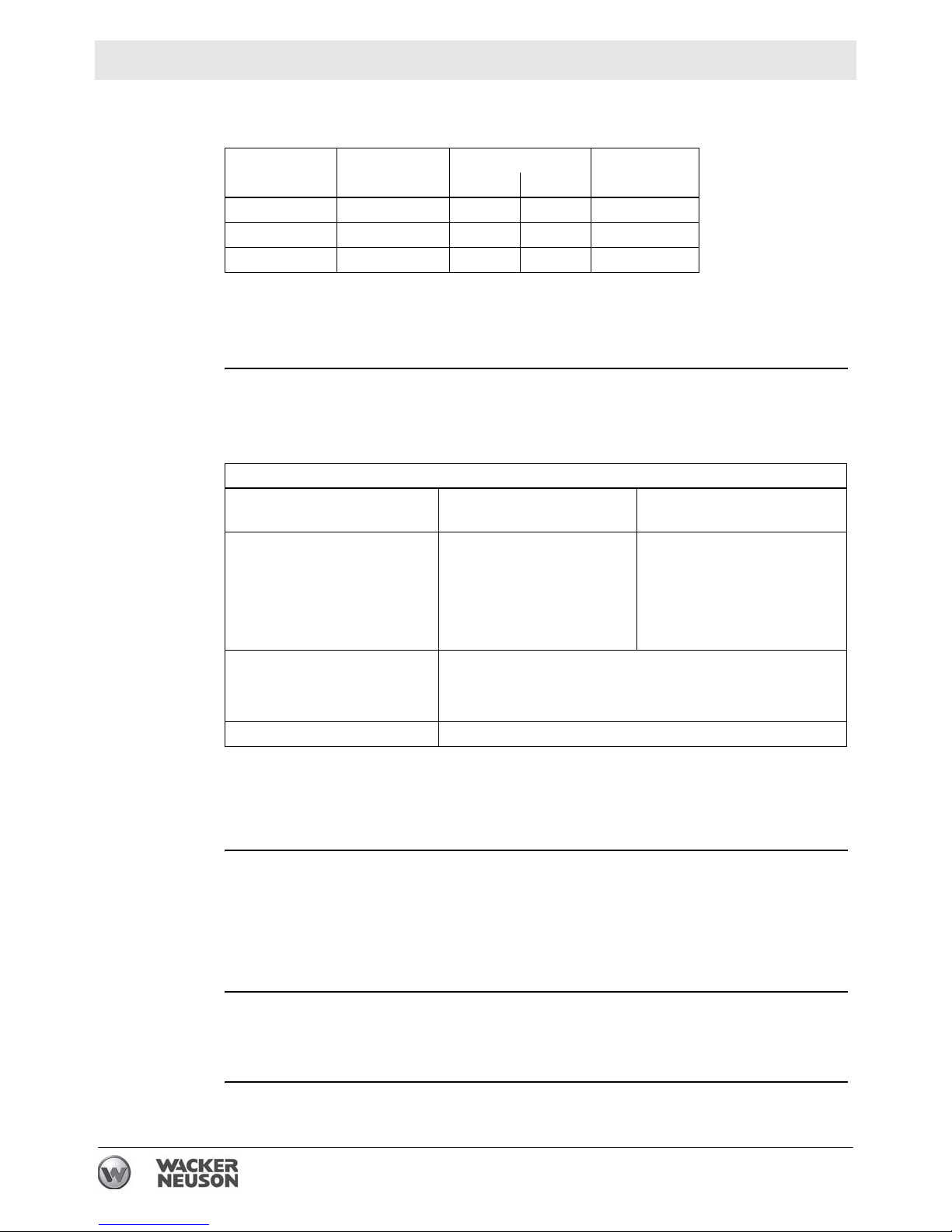
3.2 Setting Up the Burner
Factory
settings
Machine Nozzle size Fuel pressure
gph psi bar
Cub 200 1.0 x 60°A 175 12 2
Cub 300 1.5 x 80°W 175 12 3
Cub 300HD 1.35 x 80°H 218 15 5
Air band
setting
Background
Fuel
The burner consists of several different components and subsystems. Each of
these components or subsystems must be operating correctly for the burner to
function properly.
Low ambient temperatures cause diesel fuels to gel. Gelled fuels will cause burner
ignition failure and/or burner fuel pump damage. Always use the proper fuel for the
conditions.
Fuel Blend Guide
Lowest expected ambient
temperature °F (°C)
Below 5 (-15)
5 to 25 (-15 to -4)
Above 25 (-4) Winter-blend diesel
Generator powered Shore powered
50-50 blend of #2 diesel
and #1 diesel, plus
additives
OR
50-50 blend #2 diesel and
K1 kerosene, plus
additives
70-30 blend of #2 diesel and #1 diesel, plus additives
70-30 blend of #2 diesel and K1 kerosene,
plus additives
100% #1 diesel plus
additives
OR
100% K1 kerosene,
plus additives
OR
Note: The burner on this machine was calibrated by test-firing for correct op eration
at Wacker Neuson Corporation located 180 m (600 ft.) above sea level using #2
diesel fuel combined with an anti-gelling additive.
Tools required
Mandates
The following tools are required to adjust the burner:
High-quality combustion analyzer
Smoke spot tester
Fuel pressure test gauge
General hand tools
Adjustments made shall be done so that the machine conforms to the require-
ments of local, state, and federal codes and authorities.
Adjustments shall be made at the job site.
This procedure continues on the next page.
18 ghi_tx001317gb.fm
Cub 200/300 Burner Setup
Continued from the previous page.
When
Procedure
Adjust the burner:
Before operating the machine at elevations 305 m (1,000 ft) above or below the
location of where the last adjustments were made
Before starting at a new job site
After any burner maintenance or repair has been performed
If burner performance is in question
Follow the procedure below to set up the burner.
1. Shut down the machine.
2. Set the burner electrodes.
(See Section 3.4 Checking and Adjusting the Burner Electrodes on page 22.)
3. Check the burner nozzle.
(See Section 3.5 Checking and Replacing the Burner Nozzle on page 23.)
4. Set the air band.
(See Section 3.6 Setting the Air Band on page 24.)
5. Start the machine and the burner.
6. Check/set the fuel pressure.
(See Section 3.7 Checking and Adjusting the Fuel Pressure on page 25.)
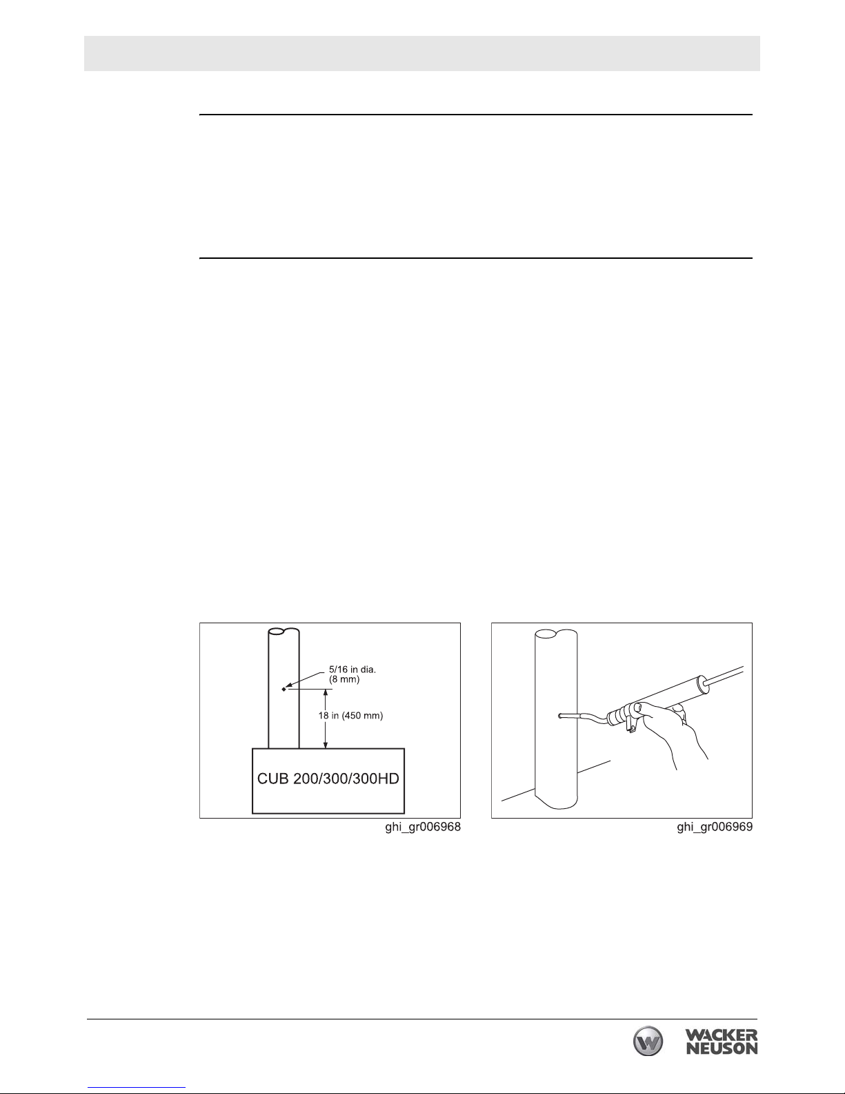
7. Conduct a smoke spot test. Follow the smoke spot tester manufacturer’s
instructions and the general guidelines below.
Use the access hole in the exhaust stack.
Several samples should be taken as the heater warms.
The final sample should be taken just before the heater reaches 71°C (160°F).
This procedure continues on the next page.
ghi_tx001317gb.fm 19

Burner Setup Cub 200/300
Continued from the previous page.
8. Analyze the combustion. Follow the combustion analyzer manufacturer’s
instructions and the general guidelines below.
Use the access hole in the exhaust stack.
Take several samples as the heater warms.
Take the final sample just before the heater reaches 71°C (160°F).
9. Re-adjust the air band, if necessary, until the smoke spot test and combustion
analysis are within the following parameters:
Result
O
content: 3–5%
2
Smoke spot: less than 1
The burner has now been set.
20 ghi_tx001317gb.fm
 Loading...