

Page 1

0170893en 006
0809
Indirect-fired Air
Heaters
Cub 200/300/300 HD
OPERATOR’S MANUAL
0170893EN
Page 2

Page 3

1 Foreword
WARNING
Foreword
CALIFORNIA
Proposition 65 Warning:
Engine exhaust, some of its constituents, and certain vehicle
components, contain or emit chemicals known to the State of
California to cause cancer and birth defects or other reproductive
harm.
This manual provides information and procedures to safely operate
and maintain this Wacker Neuson model. For your own safety and
protection from injury, carefully read, understand and observe the
safety instructions described in this manual.
Keep this manual or a copy of it with the machine. If you lose this
manual or need an additional copy, please contact Wacker Neuson
Corporation. This machine is built with user safety in mind; however, it
can present hazards if improperly operated and serviced. Follow
operating instructions carefully! If you have questions about operating
or servicing this equipment, please contact Wacker Neuson
Corporation.
The information contained in this manual was based on machines in
production at the time of publication. Wacker Neuson Corporation
reserves the right to change any portion of this information without
notice.
All rights, especially copying and distribution rights, are reserved.
Copyright 2009 by Wacker Neuson Corporation.
No part of this publication may be reproduced in any form or by any
means, electronic or mechanical, including photocopying, without
express written permission from Wacker Neuson Corporation.
Any type of reproduction or distribution not authorized by Wacker
Neuson Corporation represents an infringement of valid copyrights
and will be prosecuted. We expressly reserve the right to make
technical modifications, even without due notice, which aim at
improving our machines or their safety standards.
wcghi_tx000001gb diesel.fm 3
Page 4

Foreword
Notes:
wcghi_tx000001gb diesel.fm 4
Page 5

Table of Contents
1. Foreword 3
2. Safety Information 7
2.1 Operating Safety .................................................................................. 7
2.2 Operator Safety while using Combustion Burners ............................... 8
2.3 Service Safety ...................................................................................... 8
2.4 Label Locations .................................................................................. 10
2.5 Label Descriptions .............................................................................. 11
3. Operation 15
3.1 System Description ............................................................................ 15
3.2 Installing the Lift Brackets .................................................................. 15
3.3 System Component Locations ........................................................... 16
3.4 Mounting the Handle and Base Assembly ......................................... 17
3.5 Machine Location ............................................................................... 18
3.6 Suggested Venting ............................................................................. 18
3.7 Connecting Power to the Machine ..................................................... 20
3.8 Preliminary Checks ............................................................................ 20
3.9 Control Panel ...................................................................................... 21
3.10 Starting the Machine .......................................................................... 22
3.11 Starting the Machine in (Extreme) Cold Weather ............................... 23
3.12 Shutting Down the Machine ............................................................... 24
3.13 Using the Remote Thermostat ........................................................... 25
4. Maintenance 27
4.1 Periodic Maintenance Schedule ......................................................... 27
4.2 Removing and Installing the Burner Assembly ................................... 28
4.3 Replacing the Burner Nozzle .............................................................. 30
4.4 Replacing the Fuel Filter .................................................................... 31
4.5 Inspecting and Aligning the Burner Electrodes .................................. 32
4.6 Inspecting and Cleaning the Cadmium (CAD) Cell ............................ 33
4.7 Checking and Adjusting the Fuel Pressure ........................................ 34
4.8 Cleaning the Fan Blades and Motor ................................................... 36
4.9 Cleaning the Interior Shell .................................................................. 37
4.10 Inspecting the Flame Head ................................................................ 38
ghi_bo0170893en_006TOC.fm 5
Page 6

Table of Contents
4.11 Inspecting the Electrical Connections .................................................39
4.12 Fuel Blend Guide .................................................................................39
4.13 Transporting ........................................................................................40
4.14 List of Abbreviations ............................................................................41
4.15 Troubleshooting ...................................................................................42
4.16 Cub 200/300 Wiring Schematic ...........................................................44
4.17 Cub 300 HD Wiring Schematic ............................................................44
4.18 Schematic Legend ...............................................................................45
5. Technical Data 47
5.1 Machine Technical Data ......................................................................47
ghi_bo0170893en_006TOC.fm 6
Page 7
Cub 200/300/300 HD Safety Information
2 Safety Information
This manual contains DANGER, WARNING, CAUTION, NOTICE, and
NOTE callouts which must be followed to reduce the possibility of
personal injury, damage to the equipment, or improper service.
This is the safety alert symbol. It is used to alert you to potential
personal injury hazards. Obey all safety messages that follow this
symbol to avoid possible injury or death.
DANGER indicates a hazardous situation which, if not avoided, will
result in death or serious injury.
DANGER
WARNING indicates a hazardous situation which, if not avoided, could
result in death or serious injury.
WARNING
CAUTION indicates a hazardous situation which, if not avoided, could
result in minor or moderate injury.
CAUTION
NOTICE: Used without the safety alert symbol, NOTICE indicates a
situation which, if not avoided, could result in property damage.
Note: Contains additional information important to a procedure.
2.1 Operating Safety
Familiarity and proper training are required for the safe operation of
equipment! Equipment operated improperly or by untrained personnel
can be dangerous! Read the operating instructions contained in this
WARNING
manual and familiarize yourself with the location and proper use of all
controls. Inexperienced operators should receive instruction from
someone familiar with the equipment before being allowed to operate
the machine.
2.1.1 Be sure the machine is on a firm, level surface and will not tip, roll,
slide, or fall while operating.
2.1.2 NEVER start a machine in need of repair.
wcghi_si000212gb.fm 7
Page 8

Safety Information Cub 200/300/300 HD
2.1.3 Keep unauthorized personnel, children, and pets away from the
machine.
2.1.4 Always operate machine with all safety devices and guards in place
and in working order. Do not modify or defeat safety devices. Do not
operate machine if any safety devices or guards are missing or
inoperative.
2.1.5 NEVER run the machine indoors or in an enclosed area unless
adequate ventilation, through such items as exhaust fans or hoses, is
provided and if local and national codes permit. Exhaust from the
burner contains poisonous carbon monoxide gas. Exposure to carbon
monoxide can cause loss of consciousness and may lead to death.
2.1.6 Do not smoke while operating the machine.
2.1.7 NEVER run the machine in areas that contain flammable objects,
fuels, or products that produce flammable vapors.
2.1.8 NEVER connect ductwork between the exhaust outlet port and the
supply air inlet port.
2.1.9 NEVER block the air inlet or outlet.
2.1.10 The installation of this machine must be in accordance with the
regulations put forth by all governing bodies having jurisdiction
including the Canadian Standard B139.
2.2 Operator Safety while using Combustion Burners
2.2.1 Refill the fuel tank in a well-ventilated area.
2.2.2 Replace the fuel tank cap after refueling.
2.2.3 DO NOT spill fuel when refueling the machine. Clean up spilled fuel
immediately.
2.2.4 DO NOT smoke when refueling machine.
2.2.5 DO NOT refuel a hot or running machine.
2.2.6 The machine must be installed by qualified personnel who have read
and understand all supplied manuals and instructions.
2.2.7 When operating the machine indoors, install a carbon monoxide
detector in the work area according to the detector manufacturer’s
instructions.
2.2.8
2.3 Service Safety
HIGH VOLTAGE! This unit uses high voltage circuits capable of
causing serious injury or death. Only a qualified electrician should
troubleshoot or repair electrical problems occurring with this
WARNING
wcghi_si000212gb.fm 8
equipment.
Page 9

Cub 200/300/300 HD Safety Information
2.3.1 ALWAYS replace the safety devices and guards after repairs and
maintenance.
2.3.2 Keep the machine clean and labels legible. Replace all missing and
hard-to-read labels. Labels provide important operating instructions
and warn of dangers and hazards.
2.3.3 ALWAYS make sure slings, chains, hooks, ramps, jacks, and other
types of lifting devices are attached securely and have enough weightbearing capacity to lift or hold the machine safely. Always remain
aware of the location of other people in the area when lifting the
machine.
2.3.4 ALWAYS replace or repair electrical components with components
that are identical in rating and performance as the original component.
2.3.5 Do not use gasoline or other types of fuels or flammable solvents to
clean parts, especially in enclosed areas. Fumes from fuels and
solvents can become explosive.
2.3.6 Always wear protective epuipment when servicing the machine. Some
machine components may be hot and contain hot fluids.
2.3.7 Notes:
wcghi_si000212gb.fm 9
Page 10
Safety Information Cub 200/300/300 HD
2.4 Label Locations
wcghi_si000212gb.fm 10
Page 11
Cub 200/300/300 HD Safety Information
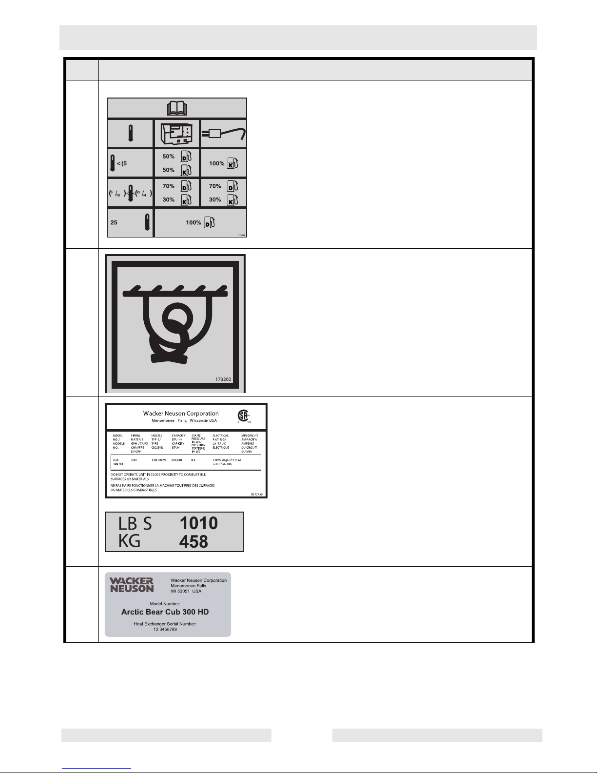
2.5 Label Descriptions
Ref. Label Label Text
1 Danger! Hazardous voltage. Do not oper-
ate without this cover in place. Disconnect
and lock out power source before opening
panel. Could cause severe injury or death.
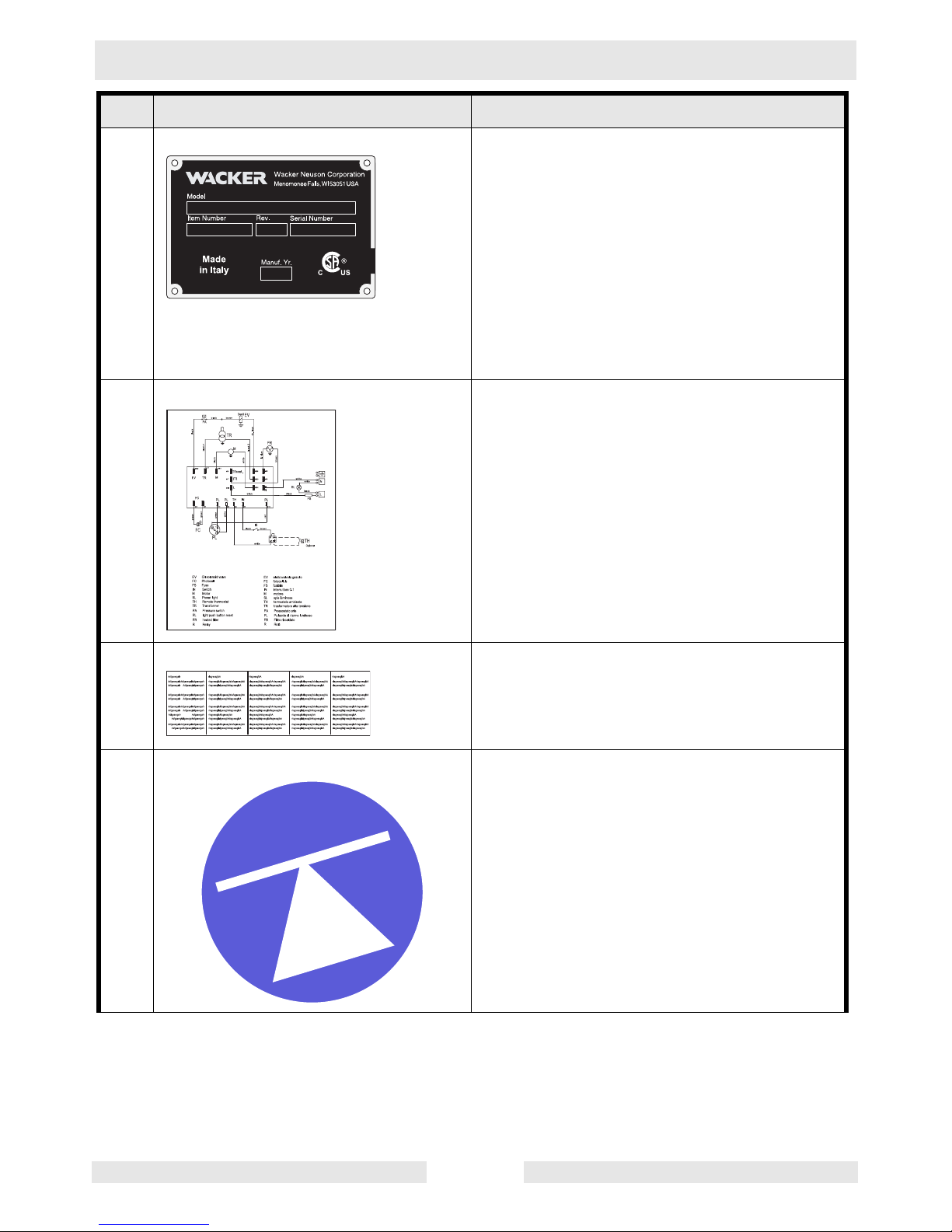
2 Warning: Blower can automatically start
which can cause serious injury. Disconnect
power source before servicing.
3 Warning: Blower can automatically start
WARNING
which can cause serious injury. Disconnect
power source before servicing.
177370
WARNUNG
ADVERTENCIA
AVERTISSEMENT
wcghi_si000212gb.fm 11
Page 12
Safety Information Cub 200/300/300 HD
D
Ref. Label Label Text
4 Using a heater indoors can kill you in min-
utes. Heater exhaust contains carbon monoxide. This is a poison you cannot see or
smell. During indoor operation, vent
exhaust gas outdoors. Refer to Operator's
Manual.
5 Warning: Electric shock hazard.
Disconnect power before servicing.
Read Operator’s Manual.
6 Danger: To avoid injury from moving parts,
DANGER
TO AVOID INJURY FROM
MOVING PARTS, SHUT OFF
THE EQUIPMENT BEFORE
REMOVING THIS COVER.
shut off the equipment before removing this
cover.
7 Caution: This machine uses diesel fuel.
CAUTION
VORSICHT
PRECAUCION
DIESEL
8 Hot surface hazard!
9 Caution: Lift point.
CAUTION
PRECAUCION
Attach lifting device in this location.
VORSICHT
PRECAUCION
PRECAUTION
wcghi_si000212gb.fm 12
Page 13
Cub 200/300/300 HD Safety Information
Ref. Label Label Text
10 Diesel fuel blend guide. This label indicates
the recommended fuel blending values for
diesel fuel usage.
11 Tie-down point.
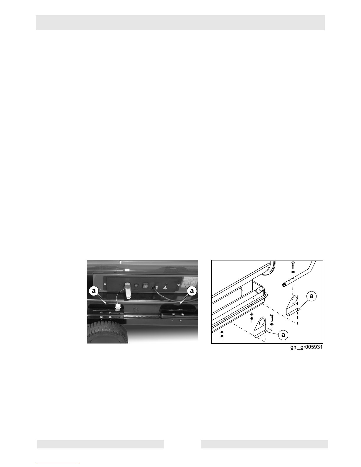
12 Machine rating label: This label indicates
rating information for the machine.
13 Weight/mass label: This label indicates the
total weight of the machine, including the
trailer and a full fuel tank.
14 Model and serial number label: This label
shows the model name and the serial number for the heat exchanger on your
machine.
wcghi_si000212gb.fm 13
Page 14
Safety Information Cub 200/300/300 HD
Ref. Label Label Text
15 A nameplate listing the model number, item
number, revision number, and serial number is attached to each unit. Please record
the information found on this plate so it will
be available should the nameplate become
16 Schematic label. This label, located behind
lost or damaged. When ordering parts or
requesting service information, you will
always be asked to specify the model number, item number, revision number, and
serial number of the unit.
the control panel, shows the electrical
schematic for the machine.
17 Installation and instruction label. This label
shows installation and operation instructions for the unit.
18 Center of gravity.
wcghi_si000212gb.fm 14
Page 15
Cub 200/300/300 HD Operation
3 Operation
3.1 System Description
The Cub series Air Heater machines are indirect-fired air heaters. The
Cub series Air Heater machines incorporate aluminized steel shells
and heat exchangers. The machines run on three fuel options: diesel,
Kerosene, or winter blend diesel (winter blend diesel is treated with
anti-gelling conditioners for use in cold weather). The fuel is consumed
in a closed combustion chamber. The exhaust gasses must be vented
outdoors through a vent pipe. The clean, dry hot air is recirculated by
means of an enclosed blower.
The Cub series Air Heater machines are intended to heat air on
construction sites and in other rugged environments. Do not use the
machines for any other purpose.
3.2 Installing the Lift Brackets
See graphic ghi_gr005931
Before attempting to lift the Cub 200 and 300 models, the lift brackets
must be installed.
3.2.1 Remove the machine from the crate.
3.2.2 Intstall the four lift brackets (a) as shown using the supplied bolts and
washers.
wcghi_tx000720gb.fm 15
Page 16
Operation Cub 200/300/300 HD
3.3 System Component Locations
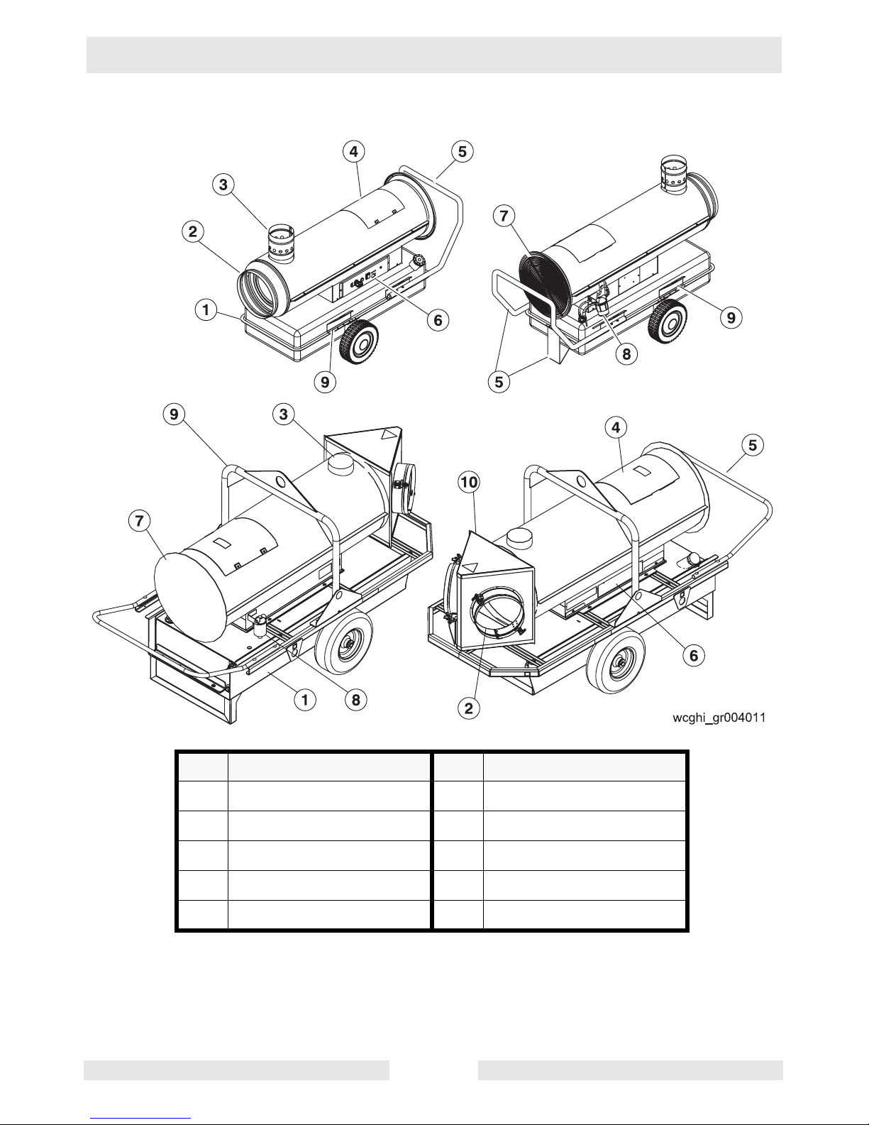
Ref Component Ref Component
1 Fuel tank 2 Air outlet
3 Flue collar (vent) 4 Burner access panel
5 Handle (and base) 6 Control panel
7 Blower 8 Fuel oil filter
9 Lifting device 10 Duct adapter
wcghi_tx000720gb.fm 16
Page 17
Cub 200/300/300 HD Operation
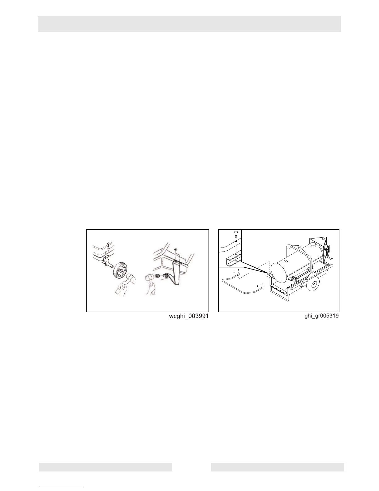
3.4 Mounting the Handle and Base Assembly
See graphics: wcghi_003991 and ghi_gr005319
The Cub series Air Heater machines are shipped partially assembled.
Before operating either machine, use the following procedure to mount
the handles and base assembly. This assembly includes the handle,
base support, and wheels with axles.
Note: There are pre-drilled bolt holes for all the components installed
within this procedure.
Note: The Cub 300 HD requires that only the handle be attached.
Refer to the procedure below to install the handle.
3.4.1 Attach the axles to the sides of the fuel tank using the supplied bolts
and washers.
3.4.2 Install the wheels using a rubber mallet to secure them to the axle
ends.
3.4.3 Attach the base support to the rear of the fuel tank using the supplied
bolts and washers.
3.4.4 Attach the handle to the machine using the supplied bolts (and
washers, if applicable).
wcghi_tx000720gb.fm 17
Page 18

Operation Cub 200/300/300 HD
3.5 Machine Location
The Air Heater machines may be located outdoors or in any
environment that requires heating. When locating a machine within the
area to be heated, the exhaust gases must be vented to the outdoors.
The machines must be installed:
• By qualified personnel who have read and understood all
supplied instructions.
• On a flat, firm surface.
• With the following minimum clearances:
• 3.05 m (10 ft.) to front.
• 0.61 m (2 ft.) to rear.
• 0.61 m (2 ft.) to sides.
• 1.52 m (5 ft.) to top.
• 0.915 m (3 ft.) to flue pipe.
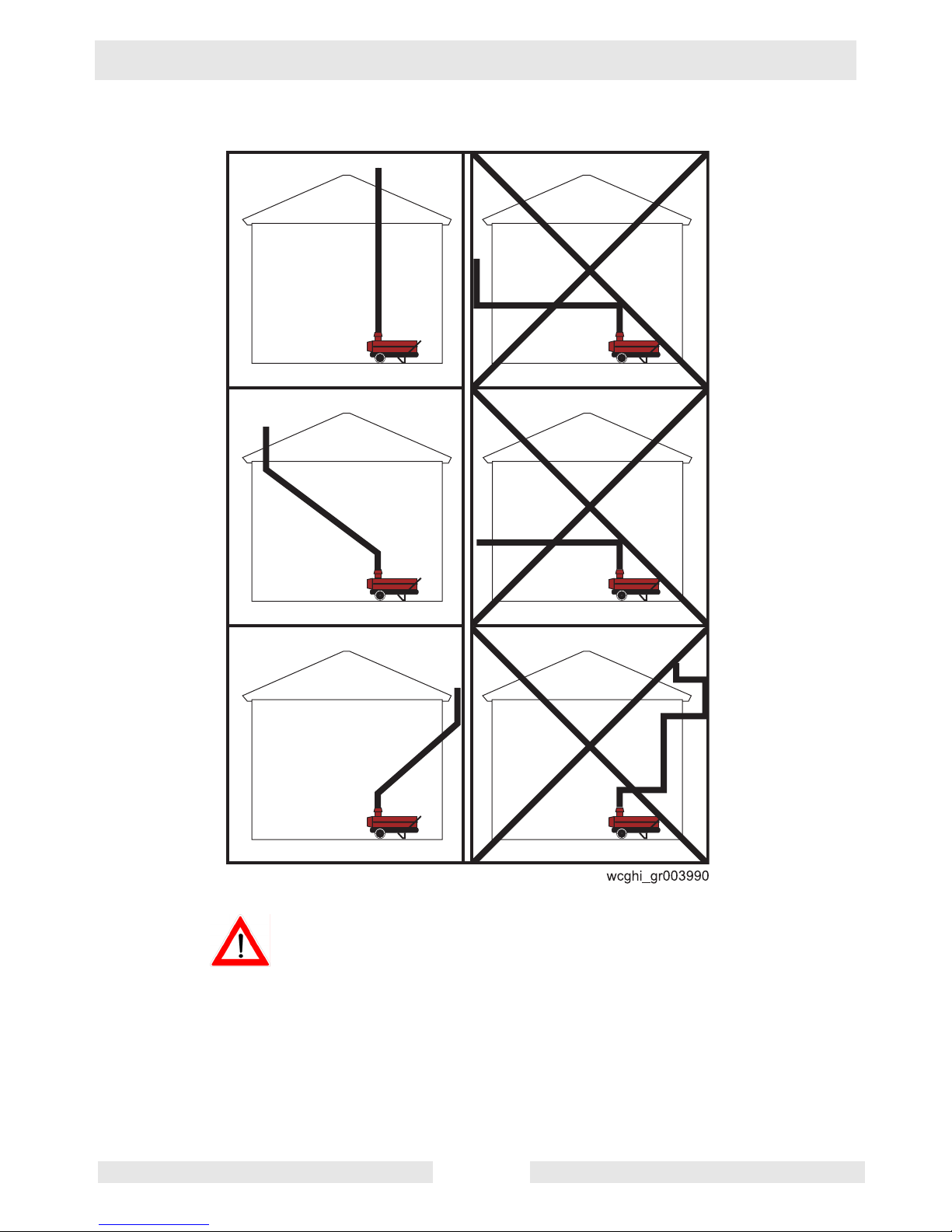
3.6 Suggested Venting
See Graphic: wcghi_gr003990
Exhaust gas from this machine CAN KILL YOU IN MINUTES. The
exhaust contains carbon monoxide, a deadly poison you can not see
or smell. This machine must be properly vented to reduce the risk of
WARNING
carbon monoxide poisoning.
When installing vents:
• Adhere to all local and national codes.
• Consult all appropriate governing bodies or local contractor for
venting and fresh air requirements.
• Place the machine in a manner that avoids excessive vent bends
(elbows), and long horizontal runs.
• Keep air inlets and outlets free from obstruction.
• Route the venting pipes in a manner that avoids any flammable
material.
• Route the venting pipes in a manner that avoids contact with
humans.
wcghi_tx000720gb.fm 18
Page 19
Cub 200/300/300 HD Operation
Exhaust gas from this machine CAN KILL YOU IN MINUTES. The
exhaust contains carbon monoxide, a deadly poison you can not see
or smell. This machine must be properly vented to reduce the risk of
WARNING
carbon monoxide poisoning.
• The above venting diagram shows suggested venting layouts
only. Consult all appropriate governing bodies or local contractor
for venting and fresh air requirements.
wcghi_tx000720gb.fm 19
Page 20

Operation Cub 200/300/300 HD
3.7 Connecting Power to the Machine
Fire and electric shock hazard. High voltage can cause severe injury
or death. This unit must be electrically grounded. Do NOT use
adapters.
WARNING
The Air Heater machines come equipped with power cords. Connect
the power cord to a grounded outlet rated for 115V, 60 Hz, 15A.
3.8 Preliminary Checks
Before starting the machine, check the following:
• Fuel supply on diesel burning machines. See Fuel Blend Guide.
• Position of power switch. It must be in the Off (“O”) position.
• Power supply. The machine must be connected to a 115V 60Hz
power supply.
• Machine location. Ensure that the machine is properly located
according to the Machine Location guidelines in this manual.
• Remote thermostat connection. If the remote thermostat will not
be used, the remote thermostat receptacle cover must be
installed.
wcghi_tx000720gb.fm 20
Page 21
Cub 200/300/300 HD Operation
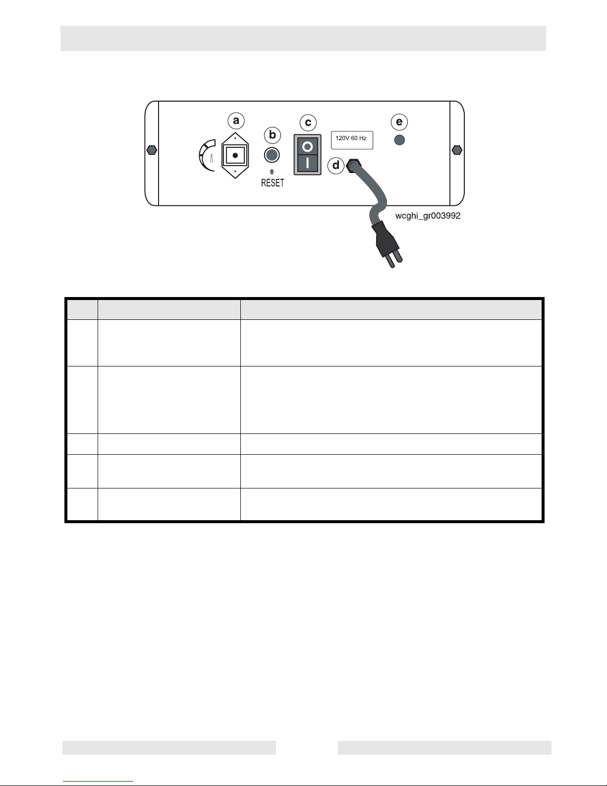
3.9 Control Panel
Ref Component Function
a Remote thermostat
receptacle
The remote thermostat receptacle (shown with protective
cap installed) is used for connecting an optional remote
thermostat
b Burner fault lamp and reset
button (dual function).
The dual function burner fault lamp and reset button:
• illuminates red when the burner has
faulted.
• resets the machine when pressed.
c Power switch The power switch provides power to the machine.
d Power cord The power cord provides a means of connecting the
machine to a 115V 60 Hz receptacle.
e Power indicator lamp The power indicator lamp illuminates green when the power
cord is connected to a 115V 60 Hz receptacle.
wcghi_tx000720gb.fm 21
Page 22

Operation Cub 200/300/300 HD
3.10 Starting the Machine
3.10.1 Perform the necessary preliminary checks. See section Preliminary
Checks.
3.10.2 If using the remote thermostat, connect it to the control panel at the
remote thermostat receptacle. Place the remote thermostat in the area
to be heated. Set it to the desired temperature.
Note: If the ambient temperature is below 32°F (0°C), it may be
necessary to preheat the fuel. See section Preheating the Fuel Filter
and Nozzle Heater.
3.10.3 Move the power switch to the On “I” position.
• The blower will turn on immediately.
• The burner will go through a prepurge cycle and then light.
• The burner will continue to fire until the temperature of the space
being heated reaches the temperature set by the thermostat. At
that time, the burner shuts down but the blower will remain on.
• If not using the remote thermostat, the blower will continue to
operate until shutdown.
wcghi_tx000720gb.fm 22
Page 23

Cub 200/300/300 HD Operation
3.11 Starting the Machine in (Extreme) Cold Weather
In temperatures below 32°F (0°C), it may be necessary to preheat the
fuel inside the fuel filter canister. The fuel filter and nozzle contain lowwattage heating elements that are controlled by a thermostat and are
specifically designed for this purpose.
Hot surface hazard.
The external surface of the fuel filter may be hot.
CAUTION
• Wear safety gloves when handling the fuel filter.
Note: Excess heating may increase the need for maintenance. See
sections “Replacing the Fuel Filter” and “Replacing the Burner Nozzle”.
To preheat the fuel, carry out the following procedure.
3.11.1 Connect power to the machine. See section Connecting Power to the
Machine.
3.11.2 Wait 20-30 minutes—longer for colder temperatures.
3.11.3 Start the machine. See section Starting the Machine.
Note: In extreme wind, the machine may need to be temporarily
blocked from the wind in order to start.
3.11.4 If the burner does not start on the first attempt, allow the power-on
sequence to cycle again (see 3.10.3).
3.11.5 If, after the second power-on sequence completes, the machine will
not fire, move the power switch to the off position.
3.11.6 Wait another 20-30 minutes and attempt to start the machine again.
wcghi_tx000720gb.fm 23
Page 24

Operation Cub 200/300/300 HD
3.12 Shutting Down the Machine
Electric shock and cutting injury hazard! At temperatures above 104°F
(40°C), electric power is available at the supply blower even with the
WARNING
3.12.1 Move the power switch to the Off (“O”) position.
3.12.2 When the blower has shut off automatically, disconnect the power
3.12.3 Disconnect the remote thermostat and re-install the receptacle cover.
operation mode switch in the OFF position. Always remove all power
to the machine before servicing it.
Note: The burner will shut down; however, the fan will continue to
operate for approximately two minutes to allow the combustion
chamber to cool.
supply cord.
wcghi_tx000720gb.fm 24
Page 25

Cub 200/300/300 HD Operation
3.13 Using the Remote Thermostat
See Graphic: wcghi_gr004009
In order for the machine to function, the remote thermostat (b) or the
receptacle cover (a) must be installed into the control panel. To use the
remote thermostat:
3.13.1 Plug (c) the remote thermostat into the control panel.
3.13.2 Set the sensor end within the space to be heated.
3.13.3 Adjust the temperature setting with dial (d).
wcghi_tx000720gb.fm 25
Page 26

Operation Cub 200/300/300 HD
Notes:
wcghi_tx000720gb.fm 26
Page 27

Cub 200/300/300 HD Maintenance
4 Maintenance
4.1 Periodic Maintenance Schedule
Replace the burner nozzle
Replace the fuel filter
Inspect the burner electrodes
Inspect and clean the Cadmium (CAD)
cell.
Check the fuel pressure
Clean the fan blades and motor
Clean the interior shell
Inspect the flame head
Inspect all electrical connections
Prior to first
seasonal use
As needed or
during regular
maintenance
Every 1200
hours
or yearly
wcghi_tx000721gb.fm 27
Page 28

Maintenance Cub 200/300/300 HD
4.2 Removing and Installing the Burner Assembly
See graphic: wcghi_gr004015
Before performing any maintenance on the burner assembly, it must
be removed from the machine. To remove or install the burner
assembly perform the following procedure:
Removal:
4.2.1 Shut down the machine and allow it to cool.
4.2.2 Disconnect the power cord from the power source.
4.2.3 Remove the two bolts (a) and open the access panel.
4.2.4 Remove the screw (d) to disconnect the ground wire (c) from the
burner assembly.
4.2.5 Rotate the burner assembly (b) counter-clockwise and remove it from
the flame head and air tube assembly (e).
4.2.6 Perform the required maintenance.
Note: Refer the maintenance procedures in this manual.
4.2.7 Re-install the burner assembly. Refer to the steps below to install the
burner assembly.
Installation:
4.2.8 Place the burner assembly into the flame head and air tube assembly
(e).
4.2.9 Rotate the burner assembly clockwise to lock it into place.
4.2.10 Install the ground wire (c) using the screw (d).
4.2.11 Close the access panel and re-install the two bolts (a) that secure the
panel.
wcghi_tx000721gb.fm 28
Page 29

Cub 200/300/300 HD Maintenance
wcghi_tx000721gb.fm 29
Page 30

Maintenance Cub 200/300/300 HD
4.3 Replacing the Burner Nozzle
See Graphic: wcghi_gr004016
To replace the burner nozzle, carry out the following procedure:
Removal:
4.3.1 Remove the burner. See section Removing and Installing the Burner
Assembly.
4.3.2 Place an adjustable wrench on the large fitting (1) on the nozzle base
(3).
4.3.3 Place another adjustable wrench on the nozzle (2).
4.3.4 Rotate the nozzle counter-clockwise and remove it from the assembly.
Installation:
4.3.5 Install the new nozzle (2) onto the nozzle base (3).
4.3.6 Tighten the nozzle (2) using an adjustable wrench. Rotate the wrench
clockwise.
4.3.7 Re-install the burner assembly. See section Removing and Installing
the Burner Assembly.
wcghi_tx000721gb.fm 30
Page 31

Cub 200/300/300 HD Maintenance
4.4 Replacing the Fuel Filter
See Graphic: wcghi_gr004019
Hot surface hazard.
The external surface of the fuel filter may be hot.
CAUTION
WARNING
• Allow the machine to cool before servicing.
• Wear safety gloves.
Hot fluids.
The fuel inside the filter canister may be hot.
• Allow the machine to cool before servicing.
• Wear safety glasses.
To replace the fuel filter (b), carry out the following procedure.
Removal:
4.4.1 Shut down the machine and allow it to cool.
4.4.2 Remove all power from the machine (unplug).
4.4.3 Remove the screw (a) that secures the cover to the housing.
4.4.4 Remove the filter (b).
Installation:
4.4.1 Install the new filter (b).
4.4.2 Inspect the rubber gasket (c) for damage.
4.4.3 Install the cover and the screw (a).
wcghi_tx000721gb.fm 31
Page 32

Maintenance Cub 200/300/300 HD
4.5 Inspecting and Aligning the Burner Electrodes
See graphic: wcghi_gr004020
To inspect and align the burner electrodes, carry out the following
procedure.
Inspection:
4.5.1 Remove the burner assembly. See section Removing and Installing
the Burner Assembly.
4.5.2 Inspect the electrodes for the following:
• Wear. Be sure to inspect the ends of the electrodes for
pitting. Replace any worn electrodes. See section
“Replacement or Alignment”.
• Straightness. Replace any bent or broken electrodes.
See section “Replacement or Alignment”.
• Corrosion and/or cleanliness. Clean the electrodes with a soft dry
cloth or replace if necessary. See section “Replacement or
Alignment”.
• Correct alignment. Align the electrodes as shown.
Replacement or Alignment:
4.5.3 Loosen the screw (1).
4.5.4 Align the electrode as shown or remove if necessary.
4.5.5 Install a new electrode if necessary.
4.5.6 Tighten the screw (1).
4.5.7 Verify the electrodes are correctly aligned.
4.5.8 Reinstall the burner. See section Removing and Installing the Burner
Assembly.
wcghi_tx000721gb.fm 32
Page 33

Cub 200/300/300 HD Maintenance
4.6 Inspecting and Cleaning the Cadmium (CAD) Cell
See Graphic: wcghi_gr004021
To inspect and clean the CAD cell, carry out the following procedure.
4.6.1 Remove the burner assembly. See section Removing and Installing
the Burner Assembly.
4.6.2 Twist and pull out the plastic protective holder (1) off the base of the
burner assembly. The CAD cell is inside this plastic holder.
4.6.3 Inspect the CAD cell for the following:
• Cleanliness. Be sure the cell is free of debris or soot.
4.6.4 Clean the cell if necessary.
NOTICE: Do NOT use solvents or liquids to clean the CAD cell. Use a
soft dry cloth to clean the CAD cell.
4.6.5 Reinstall the plastic protective holder (1) onto the base of the burner
assembly.
4.6.6 Reinstall the burner assembly. See section Removing and Installing
the Burner Assembly.
wcghi_tx000721gb.fm 33
Page 34

Maintenance Cub 200/300/300 HD
4.7 Checking and Adjusting the Fuel Pressure
See Graphic: wcghi_gr004025
To check the fuel pressure a pressure gauge is needed. To check and/
or adjust the fuel pressure, carry out the following procedure:
4.7.1 Shut down the machine and allow it to cool.
4.7.2 Disconnect the power cord from the power source.
4.7.3 Remove the two bolts (a) and open the access panel.
4.7.4 Remove the threaded plug (b) from the pressure test port using an
allen wrench. Set the plug in a safe location to be re-installed later.
4.7.5 Install a pressure gauge with adapter in the pressure test port (c).
4.7.6 Start the machine. See section Starting the Machine.
4.7.7 With the machine running, verify the fuel pressure setting. For the
correct settings, refer to the Technical Data charts in this manual.
4.7.8 Shut down the machine. See section Shutting Down the Machine.
4.7.9 Adjust the fuel pressure if necessary using the adjusting screw (e) and
re-check the settings. Repeat steps 6-8 to re-check the settings.
Do not adjust the fuel pressure to a setting outside the safe operational
parameters.
4.7.10 Remove the pressure gauge (d) from the pressure test port (c).
4.7.11 Re-install the threaded plug (b) into the pressure test port (c).
4.7.12 Close the access panel and re-install the two bolts (a) that secure the
panel.
wcghi_tx000721gb.fm 34
Page 35

Cub 200/300/300 HD Maintenance
wcghi_tx000721gb.fm 35
Page 36

Maintenance Cub 200/300/300 HD
4.8 Cleaning the Fan Blades and Motor
See graphic: wcghi_gr004030
To clean the fan blades and motor, carry out the following procedure:
4.8.1 Shut down the machine and allow it to cool.
4.8.2 Disconnect the power cord from the power source.
4.8.3 Remove the fan guard. There are four screws that secure the guard.
4.8.4 Remove the six bolts that secure the top portion of the shell.
4.8.5 Remove the top shell to access the interior of the machine.
4.8.6 Inspect and, if necessary, clean the motor using compressed air.
4.8.7 Clean the fan blades using a brush.
4.8.8 Re-install the top shell using the six bolts.
4.8.9 Re-install the fan guard.
wcghi_tx000721gb.fm 36
Page 37

Cub 200/300/300 HD Maintenance
4.9 Cleaning the Interior Shell
See graphic: wcghi_gr004029
To clean the interior shell, carry out the following procedure:
4.9.1 Shut down the machine and allow it to cool.
4.9.2 Disconnect the power cord from the power source.
4.9.3 Remove the fan guard. There are four screws that secure the guard.
4.9.4 Remove the six bolts that secure the top portion of the shell.
4.9.5 Remove the top shell to access the interior of the machine.
4.9.6 Inspect and, if necessary, clean the interior shell using compressed air.
4.9.7 Re-install the top shell using the six bolts.
4.9.8 Re-install the fan guard.
wcghi_tx000721gb.fm 37
Page 38
Maintenance Cub 200/300/300 HD
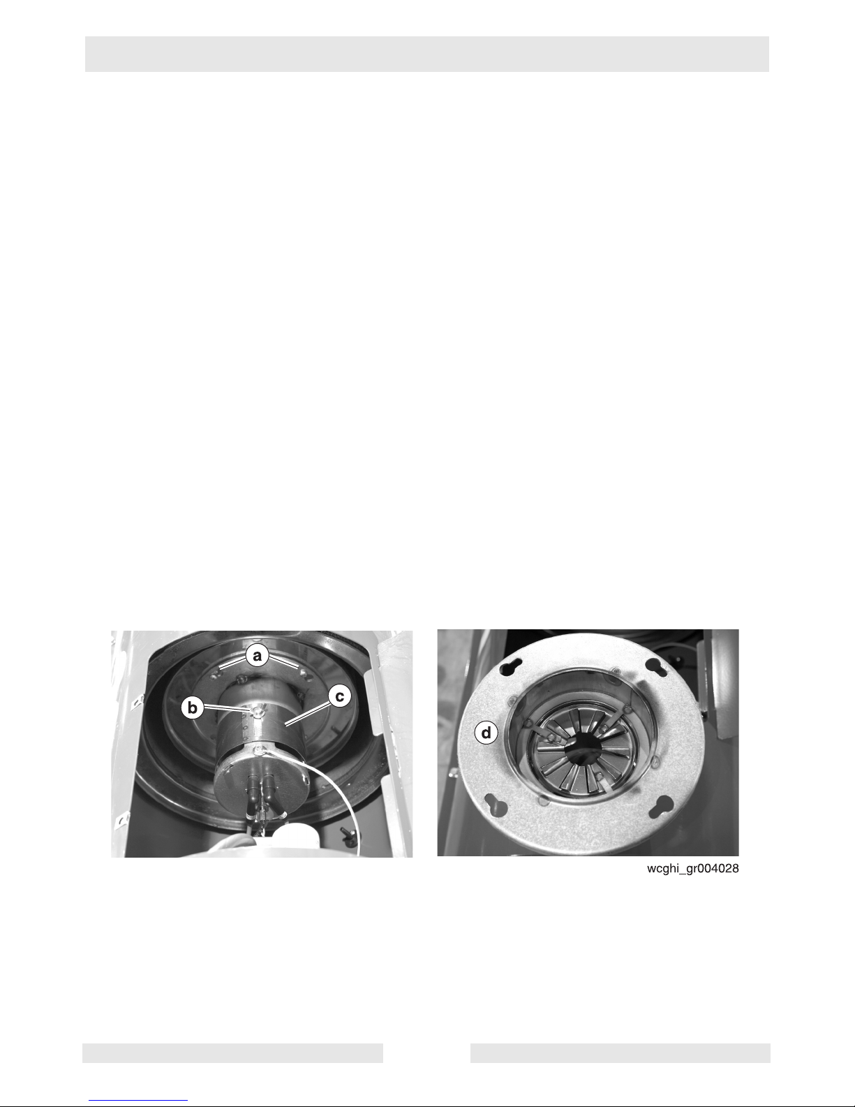
4.10 Inspecting the Flame Head
See Graphic: wcghi_gr004028
To inspect the flame head, carry out the following procedure:
4.10.1 Remove the burner assembly. See section Removing and Installing
the Burner Assembly.
4.10.2 Mark the location of the air lock sleeve (c) with a pencil.
4.10.3 Loosen the wing nut (b).
4.10.4 Loosen the four screws (a) that secure the flame head (d).
4.10.5 Turn the flame head (d) counter-clockwise and remove.
4.10.6 Inspect the flame head (d) for the following:
• Wear. Replace if necessary.
• Cleanliness. Clean the flame head if necessary.
• Thermal stress. Replace if necessary.
4.10.7 Re-install the flame head (d).
4.10.8 Position the air lock sleeve (c) at the marked location.
4.10.9 Tighten the wing nut (b).
4.10.10 Tighten the four screws (a).
4.10.11 Re-install the burner assembly. See section Removing and Installing
the Burner Assembly.
wcghi_tx000721gb.fm 38
Page 39

Cub 200/300/300 HD Maintenance
4.11 Inspecting the Electrical Connections
After disconnecting the power cord, check all electrical connections for
the following:
• Proper connections. Be sure that all connections are complete and
tight.
• Corrosion. Clean or replace if necessary.
• Damaged wires/connectors. Replace if necessary.
• Proper ground.
4.12 Fuel Blend Guide
Fuel Blend Guide
Temperature Range
Fuel Blend
15° to 30°F 80% #2 : 20% #1
0° to 15°F 70% #2 : 30% #1
–15° to 0°F 50% #2 : 50% #1
below –15°F 30% #2 : 70% #1
wcghi_tx000721gb.fm 39
Page 40

Maintenance Cub 200/300/300 HD
4.13 Transporting
Cub series Air Heater machines must be supported by use of blocks
during transport. NOTICE: DO NOT strap or chain down the unit with
the foot or wheels in contact with the transporter.
• Openings or the entire unit should be covered during transport to
avoid road debris and clutter.
• Take care when placing straps on areas which are painted red.
Use corner protectors and never use chains.
• Excessive loading on the foot, wheels, and axle will cause
permanent damage
• The foot and wheels are for moving by hand and for parking only.
• This unit is not designed to be towed with any vehicle.
• All venting external to the machine must be removed prior to
transporting.
• Only qualified riggers should attempt aerial lifting.
wcghi_tx000721gb.fm 40
Page 41

Cub 200/300/300 HD Maintenance
4.14 List of Abbreviations
Amp ampere (unit of electrical current)
asl above sea level
BTU British Thermal Unit
°C Celsius (metric unit of temperature)
°F Fahrenheit (unit of temperature)
2
ft
square foot/square feet (measurement of area)
ft.lbs. foot pounds (unit of torque)
gph gallons per hour (unit of liquid flow)
GFI Ground Fault Interrupt(er) (protection device)
Hz Hertz (unit of frequency)
ID inner diameter
in. inch
kg kilogram
kilo-cal kilo-calorie (1000 calories) (metric unit of heat energy)
kPal kilo-Pascals (metric unit of pressure)
kW kilo-Watt (unit of electrical power)
lb. pound
m meter
mm millimeter (1/1000 of a meter)
psig pounds per square inch gauge (unit of pressure)
VAC Volts, Alternating Current
VDC Volts, Direct Current
VFD Variable Frequency Drive
HTF Heat Transfer Fluid
wcghi_tx000721gb.fm 41
Page 42
Maintenance Cub 200/300/300 HD
4.15 Troubleshooting
Note: The following symptoms and remedies are some of the more
common issues that have arisen during the history of these machines.
These do not represent all the possibilities. If you need advanced
troubleshooting assistance, please contact Wacker Neuson Product
Support.
Symptom Possible Causes Remedy
The burner does not start • The remote thermostat
or thermostat plug is not
inserted correctly.
• Faulty cable or power
supply
• The over temperature
limit has tripped
• The burner is in lock-out
mode.
The burner starts, the flame
does not ignite, the unit
locks out
• No fuel
• Worn burner nozzle
• Faulty electrodes
• Cad cell detecting
external light.
• Cad cell defective
• Burner control defective
The burner starts, flame
ignites, but the unit locks
out
• Incorrect fuel pressure
• Worn burner nozzle
• Incorrect air lock setting
• Cad cell defective
• Burner control defective
• Insert the remote
thermostat or thermostat
plug.
• Check cable and power
supply
• Press the reset button.
• Fill fuel tank
• Replace burner nozzle
• Replace electrodes
• Check the Cad cell
enclosure
• Increase fuel pressure
• Replace burner nozzle
• Re-adjust air lock setting
The burner ignites but the
performance is poor
Black smoke from vent pipe • Insufficient combustion
The machine stops due to
pressure switch fault
wcghi_tx000721gb.fm 42
• Worn burner nozzle
• Clogged fuel filter
• Air leaks in the fuel lines
• Insufficient oil pressure
air
• Insufficient ventilation air
• Overheat condition
• Faulty pressure switch
• Replace burner nozzle
• Replace the fuel filter
• Inspect the lines for
leaks; replace if
necessary
• Remove any
obstructions from the air
inlet and outlet areas.
• Contact Wacker Neuson
Product Support
Page 43

Cub 200/300/300 HD Maintenance
Notes:
wcghi_tx000721gb.fm 43
Page 44

Maintenance Cub 200/300/300 HD
4.16 Cub 200/300 Wiring Schematic
4.17 Cub 300 HD Wiring Schematic
wcghi_tx000721gb.fm 44
Page 45

Cub 200/300/300 HD Maintenance
4.18 Schematic Legend
Ref. Description Ref. Description
Fuel solenoid valve
a
Photo cell
b
Fuse
c
ON-OFF switch
d
Motor
e
Power light
f
Remote thermostat
g
Transformer
h
Pressure switch
i
Push button reset light
j
Heated filter
k
Relay
l
Temperature limit control
m
Capacitor
n
Air temperature switch
o
Nozzle preheater
p
wcghi_tx000721gb.fm 45
Page 46

Maintenance Cub 200/300/300 HD
wcghi_tx000721gb.fm 46
Page 47

Cub 200/300/300 HD Technical Data
5 Technical Data
5.1 Machine Technical Data
Item Number
Model
0620204
0620262
Cub 200
0620233
Cub 300
0620253
Cub 300 HD
Units
Heat input BTU/hr 180,000 289,000 289,000
Heat output BTU/hr 147,000 232,000 232,000
Air flow cfm 1300 2600 2600
Fuel consumption L (gal)/hr 4.85 (1.28) 7.72 (2.04) 7.72 (2.04)
Fuel nozzle size gal/hr-deg 1.00-60 1.5-80 1.35-80
Efficiency % 81.5 80 80
Noise level at 2 m dB (A) 73 71 73.9 (at 3 m)
Power requirement VAC/Hz 115/60 115/60 115/60
Electrical current Ampere 7 12 14
Weight (no fuel) kg (lb) 79.4 (175) 116.1 (256) 264(583)
Height cm (in.) 78.7 (31) 116.8 (46) 130.8(51.5)
Length cm (in.) 139.7 (55) 172.7 (68) 228.3(89.9)
Width cm (in.) 61 (24) 69.9 (27.5) 97.5(38.4)
Flue diameter cm (in.) 15.2 (6) 15.2 (6) 15.2 (6)
Fuel tank capacity L (gal) 100 (26.42) 138.9 (36.7) 232.8(61.5)
Fuel pressure psi 175 175 218
Air lock setting number 2 3 5
wcghi_td000213gb.fm 47
Page 48

Technical Data Cub 200/300/300 HD
wcghi_td000213gb.fm 48
Page 49

Page 50

Wacker Neuson SE · Preußenstraße 41 · D-80809 München · Tel.: +49-(0)89-3 54 02-0 · Fax: +49 - (0)89-3 54 02-390
Wacker Neuson Corporation · P.O. Box 9007 · Menomonee Falls, WI 53052-9007 · Tel. : (262) 255-0500 · Fax: (262) 255-0550 · Tel. : (800) 770-0957
Wacker Neuson Limited - Room 1701–03 & 1717–20, 17/F. Tower 1, Grand Century Place, 193 Prince Edward Road West, Mongkok, Kowloon, Hongkong.
Tel: (852) 3605 5360, Fax: (852) 2758 0032
Page 51

www.wackerneuson.com
0620253 105
05.2010
Portable Indirect Air Heaters
Fahrbare Kaminheizgeräte
Calentadores de aire indirectos portátiles
Réchauffeurs indirects d'air (portatifs)
CUB 300HD
Parts Book
Ersatzteile
Lista de Repuestos
Liste de Pièces de Rechange
Page 52

Page 53

A nameplate listing the Model Number, Item Number, Revision, and Serial Number is
attached to each unit. Please record the information found on this plate so it will be available
should the nameplate become lost or damaged. When ordering parts or requesting service
information, you will always be asked to specify the model, item number, revision number,
and serial number of the unit.
Ein Typenschild mit Typ, Artikelnummer, Version und Maschinen-Nummer ist an jedem
Gerät angebracht. Die Daten von diesem Schild bitte notieren, damit sie auch bei Verlust
oder Beschädigung des Schildes noch vorhanden sind. Der Typ, die Artikel-Nummer, die
Versions- Nummer und die Maschinen-Nummer sind bei der Ersatzteilbestellung oder
Nachfragen bezüglich Service-Informationen stets erforderlich.
Una placa de identificación con el modelo, número de referencia, nivel de revisión y número
de serie ha sido añadida en cada máquina. Favor de anotar los datos en la placa en caso
de que la placa de identificación sea destruida o perdida. En todos los pedidos para
repuestos necesita siempre el modelo, el número de referencia, el nivel de revisión y el
número de serie de la máquina en cuestión.
Une plaque signalétique mentionnant le modèle, le numéro de référence, le niveau de
revision et le numéro de série est fixée sur chaque machine. Veuillez noter les informations
relevées sur cette plaque de façon à ce qu’elles soient toujours disponibles si la plaque
signalétique venait à être perdue ou endommagée. Lorsq ue vous commandez des pièces
détachées ou vous sollicitez des informations après-vente, on vous demandera toujours de
préciser le modèle, le numéro de référence, le niveau de revision et le numéro de série de
la machine.
My machine’s numbers are / Die Nummern meines Gerätes sind /
Los números de mi máquina son / Les numéros de ma machine son :
CUB 300HD
Nameplate
Typenschild
Plaque signalétique
Placa de Identificación
0620253 - 105
3
Page 54

Part Numbers appearing in boldface type are recommended spare parts. This means that
these parts are subject to wear under normal operating conditions and may require periodic
service or replacement. It is recommended that these items be stocked to meet the
expected service requirements of this model. Actual stocking quantities of these and other
parts used in more extensive repairs will depend on the service practices of each customer.
Bei den in den Ersatzteillisten fettgedruckten Nummern handelt es sich um empfohlene
Ersatzteile. Dies bedeutet, daß diese Teile bei normalen Anwendungsbedingungen
natürlicher Abnutzung ausgesetzt sind und gelegentlich ersetzt oder überarbeitet werden
müssen. Es wird geraten, diese Teile auf Lager bereit zu haben, um für Service-Arbeiten an
diesem Gerät vorbereitet zu sein. Lagerbestände für diese und andere Teile, welche für
ausgiebigere Reparaturarbeiten benötigt werden, können je nach Service-Gewohnheiten
der einzelnen Kunden variieren.
Los números de partes en negritas en las Listas Ilustradas de Partes son los repuestos
recomendados, ésto quiere decir que estas partes se desgastarán bajo circunstancias de
funcionamiento normales y pueden requerir servicio periódico o su reemplazo. Se
recomienda que el cliente mantenga un abastecimiento adecuado de estas partes para
poder satisfacer la demanda requerida por el servicio a la máquina. La cantidad de
repuestos que el cliente necesitará para reparaciones dependerá de la póliza de servicio de
cada cliente.
Les numéros de pièces imprimés en caractères gras dans les Listes des Pièces Détachées
de ce manuel sont les pièces détachées recommandées par la Wacker. Cela veut dire que
ces pièces sont sujettes à usure dans des conditions de travail normales et peuvent
nécessiter de l’entretien ou leur remplacement. Nous recommandons que vous disposez
d’un stock de ces pièces pour pouvoir satisfaire la demande d’entretien de cette machine.
Le client doit decider lui-même de la quantité exacte de pièces de rechange qu’il disposera
dans ses stocks.
Part Numbers - Boldface
Fettgedruckte Artikelnummern
CUB 300HD
Números de partes en negritas
Numéros de pièce - en caractères gras
4
0620253 - 105
Page 55

Heater
Heizung
Calentador
Réchauffeur
6
Frame/Components
Rahmen/Bestandteile
Chasis/Componentes
Châssis/Composants
12
Labels
Aufkleber
Calcomanias
Autocollants
16
CUB 300HD
Table of Contents
Inhaltsverzeichnis
Indice
Table des matières
0620253 - 105
5
Page 56

Heater
Heizung
CUB 300HD
Calentador
Réchauffeur
6
0620253 - 105
Page 57

Ref.
Pos.
Part No.
Artikel Nr.
Qty.
St.
Description
Beschreibung
Descripción
Description
Measurem./Abm.
Torque/Drehm.
Norm
Sealant
Schmierstoff
1 0172597 1
Fan
Gebläserad
Ventilador
Ventilateur
2 0172598 1
Motor-fan
Motor, Lüfter
Motor-ventilador
Moteur - ventilateur
3 0172092 1
Adapter fan
Adapter, Lüfter
Ventilador adaptador
Adaptateur, ventilateur
4 0172599 1
Capacitor-fan
Kondensator, Lüfter
Condensador-ventilador
Condensateur - ventilateur
5 0172093 1
Solenoid coil
Solenoidwindung
Bobina del solenoide
Bobine du solénoïde
6 0172094 2
Cable-fuel pump
Kabel, Kraftstoffpumpe
Cable-bomba de combustible
Câble - pompe à carburant
7 0172095 1
Hose-fuel
Kraftstoffschlauch
Manguera-combustible
Flexible - carburant
8 0172096 1
Fitting-fuel D
Verschraubung, Kraftstoff D
Unión-combustible D
Raccord - carburant D
9 0172600 1
Pump-fuel
Kraftstoffpumpe
Bomba-combustible
Pompe - carburant
10 0172097 2
Washer
Scheibe
Arandela
Rondelle
11 0172098 3
Fitting-fuel B
Verschraubung, Kraftstoff B
Unión-combustible B
Raccord - carburant B
12 0172099 5
Fitting-fuel A
Verschraubung, Kraftstoff A
Unión-combustible A
Raccord - carburant A
13 0172100 2
Fitting-fuel C
Verschraubung, Kraftstoff C
Unión-combustible C
Raccord - carburant C
14 0172601 2
Hose-back flow
Schlauch, Rückfluss
Manguera-retroflujo
Flexible - retour
15 0172102 2
Hose-return fuel
Schlauch, Rückleitung, Kraftstoff
Manguera-combustible de retorno
Flexible - retour carburant
16 0170280 1
Sensor-flame
Flammensensor
Sensor-llama
Capteur - flamme
17 0172103 2
Cable-electrode
Kabelelektrode
Cable-electrodo
Câble - électrode
18 0180719 1
Head-flame
Vibrationsflasche, Flamme
Cabezal-llama
Tête - flamme
20 0170282 2
Electrode
Elektrode
Electrodo
Électrode
21 0172105 1
Cover-electric panel
Abdeckung, Schaltfeld
Tapa-panel eléctrico
Couvercle - tableau électrique
22 0170283 1
Transformer
Transformator
Transformador
Transformateur
23 0170284 1
Lamp
Lampe
Lámpara
Voyant
24 0170285 1
Switch, on/off
Schalter, ein/aus
Interruptor, enc./apag.
Interrupteur, marche/arrêt
25 0172107 1
Cable-power
Kabel, Strom
Cable-alimentación
Câble - alimentation
26 0172603 1
Fuse
Sicherung
Fusible
Fusible
CUB 300HD
Heater
Heizung
Calentador
Réchauffeur
0620253 - 105
7
Page 58

Heater
Heizung
CUB 300HD
Calentador
Réchauffeur
8
0620253 - 105
Page 59

Ref.
Pos.
Part No.
Artikel Nr.
Qty.
St.
Description
Beschreibung
Descripción
Description
Measurem./Abm.
Torque/Drehm.
Norm
Sealant
Schmierstoff
27 0170287 1
Reset-pushbutton
Rückstellungsdrucktaste
Restablecimiento-botón
Réinitialisation - bouton - poussoir
28 0172109 1
Plug-thermostat
Stecker, Temperaturregler
Tapón-termostato
Fiche - thermostat
29 0170313 1
Thermostat socket
Temperaturregler, Buchse
Toma para el termostato
Thermostat, douille
30 0176675 1
Housing
Gehäuse
Caja
Carter
31 0172112 1
Control panel
Schalttafel
Tablero de mando
Tableau de commande
32 0176676 1
Spacer
Abstandsstück
Espaciador
Entretoise
33 0170288 1
Burner control
Brennerbetätigung
Control del quemador
Commande de brûleur
36 0176678 1
Suction hose
Saugschlauch
Manguera de succión
Tuyau de succion
37 0172114 1
Fitting-fuel E
Verschraubung, Kraftstoff E
Unión-combustible E
Raccord - carburant E
39 0172115 1
Nut-fuel line
Mutter, Kraftstoffleitung
Tuerca-línea de combustible
Écrou - conduite de carburant
40 0172116 1
Bracket-filter
Halterung, Filter
Ménsula-filtro
Support - filtre
41 0172117 1
Fitting-fuel F
Verschraubung, Kraftstoff F
Unión-combustible F
Raccord - carburant F
42 0176682 1
Filter-oil, heated
Ölfilter, erwärmt
Filtro-aceite, caliente
Filtre - huile, chauffée
48 0172123 1
Fitting-fuel suction
Verschraubung, Kraftstoffansaugung
Unión-succión de combustible
Raccord - aspiration carburant
50 0172605 1
Guard-fan
Schutz, Lüfter
Protector-ventilador
Protection - ventilateur
51 0172606 1
Rim-fan
Rand, Lüfter
Aro-ventilador
Couronne - ventilateur
52 0172607 1
Cover-inspection
Abdeckung, Inspektion
Tapa-inspección
Couvercle - inspection
53 0176679 1
Panel-top
Panel, oben
Panel-superior
Panneau - haut
55 0172129 2
Grommet
Tülle
Ojal
Passe-fil
56 0172130 2
Grommet
Tülle
Ojal
Passe-fil
65 0172137 1
Cover-air, burner
Abdeckung, Luft, Brenner
Tapa-aire, quemador
Couvercle - air, brûleur
66 0172612 1
Head-flame
Vibrationsflasche, Flamme
Cabezal-llama
Tête - flamme
67 0172613 1
Cylinder-combustion
Zylinder, Verbrennung
Cilindro-combustión
Cylindre - combustion
68 0172614 1
Cover-heat
Abdeckung, Heizung
Tapa-calor
Couvercle - chaleur
69 0176680 1
Duct adapter kit
Luftleitblechadaptersatz
Juego adaptador del conducto
Jeu d?adaptateur de conduit
CUB 300HD
Heater
Heizung
Calentador
Réchauffeur
0620253 - 105
9
Page 60

Heater
Heizung
CUB 300HD
Calentador
Réchauffeur
10
0620253 - 105
Page 61

Ref.
Pos.
Part No.
Artikel Nr.
Qty.
St.
Description
Beschreibung
Descripción
Description
Measurem./Abm.
Torque/Drehm.
Norm
Sealant
Schmierstoff
70 0172140 1
Stack-flue
Schacht, Luftklappe
Tubo-cañón
Cheminée - conduit
71 0172141 6
Clip-cover
Klemme, Abdeckung
Sujetador-tapa
Couvre - attache
72 0172616 1
Panel-bottom
Boden-Panel
Panel inferior
Tableau - fond
73 0176681 1
Thermostat
Temperaturregler
Termóstato
Thermostat
74 0180715 1
Pressure Switch
Druckschalter
Interruptor de Presión
Interrupteur à Pression
75 0172143 1
Bracket-air pressure gauge
Halterung, Luftdruckmesser
Ménsula-indicador de presión de aire
Support - manomètre d'air
77 0172145 1
Fitting-air hose
Verschraubung, Luftschlauch
Unión-manguera de aire
Raccord - flexible d'air
80 0172118 1
Cover-fuel filter
Abdeckung, Kraftstofffilter
Tapa-filtro de combustible
Couvercle - filtre à carburant
82 0170290 1
Filter cartridge
Filterpatrone
Cartucho del filtro
Cartouche de filtre
83 0180717 1
Heating element
Heizelement
Elemento de calefacción
Élément chauffant
200W
84 0172122 1
Casing-fuel filter
Umhüllung, Kraftstofffilter
Envoltura-filtro de combustible
Gaine - filtre à carburant
85 0172108 1
Cover-reset button
Abdeckung, Rückstelltaste
Tapa-botón de restablecimiento
Couvercle - bouton de réinitialisation
86 0176683 1
Gasket Kit
Dichtungssatz
Juego de juntas
Jeu de joints
91 0180716 1
Cover
Deckel
Tapa
Couvercle
92 0180718 1
Thermostat
Temperaturregler
Termóstato
Thermostat
93 0172649 1
Adapter-fuel
Adapter, Kraftstoff
Adaptador-combustible
Adaptateur - combustible
CUB 300HD
Heater
Heizung
Calentador
Réchauffeur
0620253 - 105
11
Page 62

Frame/Components
Rahmen/Bestandteile
CUB 300HD
Chasis/Componentes
Châssis/Composants
12
0620253 - 105
Page 63

Ref.
Pos.
Part No.
Artikel Nr.
Qty.
St.
Description
Beschreibung
Descripción
Description
Measurem./Abm.
Torque/Drehm.
Norm
Sealant
Schmierstoff
1 0173663 1
Upper frame
Oberer Rahmen
Chasis superior
Châssis supérieur
2 0173665 1
Fuel tank
Kraftstofftank
Depósito de combustible
Réservoir de carburant
3 0173671 1
Lifting bracket
Hebebügel
Ménsula alzadora
Support de relèvement
4 0173664 1
Lower frame
Unterer Rahmen
Chasis inferior
Châssis inférieur
5 0173879 1
Lifting bail handle
Tragegriff
Manija de Agarradero de izar
Poignée de relèvement
7 0173927 2
Mounting bracket
Konsole
Ménsula
Support
9 0177335 1
Fuel tank bracket
Kraftstofftankkonsole
Ménsula de tanque de combustible
Support de réservoir de carburant
200 0173670 1
Heater core
Heizung, Wellenseele
Núcleo del calentador
Réchauffeur, Âme
201 0177156 2
Wheel
Rad
Rueda
Roue
16,3 OD, 760lb
202 0170453 1
Gauge-fuel
Kraftstoffanzeiger
Indicador-combustible
Jauge - carburant
S9
203 0168154 1
Plug
Stopfen
Tapón
Bouchon
3/4in NPT
S9
204 0173890 1
Fuel tank cap
Tankverschluß
Tapa del tanque
Chapeau de réservoir
2,50in
205 0173998 2
Cap
Kappe
Tapa
Capuchon
207 0168611 2
Clip
Clip
Clip
Clip
1/16in
500 0010374 42
Flat washer
Scheibe
Arandela elástica
Rondelle de ressort
B8,4
501 0011457 22
Hex head screw
Sechskantschraube
Tornillo
Vis à tête hexagonale
M8 x 25
20Nm/14ft.lbs
502 0033198 54
Lock washer
Federring
Federring
Rondelle de ressort
B8
503 0010882 24
Hex nut
Sechskantmutter
Tuerca hexagonal
Écrou six-pans
M8
504 0010373 5
Fender washer
Unterlegscheibe
Arandela
Rondelle
B6,4
505 0173995 4
Bolt
Bolzen
Perno
Boulon
M8 x 45
506 0011470 2
Hexagonal head cap screw
Sechskantschraube
Tornillo hexagonal
Boulon à tête hexagonale
M6 x 20
10Nm/7ft.lbs
507 0173987 4
Lock washer
Federring
Federring
Rondelle de ressort
No.6
508 0173988 2
Hexagon nut
Sechskantmutter
Tuerca hexagonal
Écrou hexagonal
M6
510 0025661 4
Cotter pin
Sicherungssplint
Clavija hendida
Goupille fendue
1/8 x 1-3/4in
511 0025641 4
Flat steel washer
Scheibe
Arandela
Rondelle
1in
CUB 300HD
Frame/Components
Rahmen/Bestandteile
Chasis/Componentes
Châssis/Composants
0620253 - 105
13
Page 64

Frame/Components
Rahmen/Bestandteile
CUB 300HD
Chasis/Componentes
Châssis/Composants
14
0620253 - 105
Page 65

Ref.
Pos.
Part No.
Artikel Nr.
Qty.
St.
Description
Beschreibung
Descripción
Description
Measurem./Abm.
Torque/Drehm.
Norm
Sealant
Schmierstoff
512 0167806 2
Fender washer
Unterlegscheibe
Arandela
Rondelle
1/4 x 3/4in
513 0028404 2
Hexagonal flange head screw
Sechskantflanschschraube
Tornillo hexagonal de brida
Vis hexagonale de bride
M8 x 20
20Nm/14ft.lbs
514 0178277 1
Washer
Scheibe
Arandela
Rondelle
24mm ID
S9
515 0179112 1
Clamp
Schelle
Abrazadera
Agrafe
3/8in ID
600 0177336 1
Ground wire
Erdungsdraht
Alambre a tierra
Fil de masse
801 0181250 1
Nut
Mutter
Tuerca
Écrou
802 0183685 1
Gasket
Dichtung
Junta
Joint
CUB 300HD
Frame/Components
Rahmen/Bestandteile
Chasis/Componentes
Châssis/Composants
0620253 - 105
15
Page 66

Labels
Aufkleber
CUB 300HD
Calcomanias
Autocollants
16
0620253 - 105
Page 67

Ref.
Pos.
Part No.
Artikel Nr.
Qty.
St.
Description
Beschreibung
Descripción
Description
Measurem./Abm.
Torque/Drehm.
Norm
Sealant
Schmierstoff
1 0176654 1
Label -logo
Aufkleber, Logo
Calcomanía -logotipo
Autocollant - logo
2 0176655 1
Label-warning
Aufkleber-Warnung
Calcomania-Advertencia
Autocollant-Avertissement
3 0176656 1
Label-instruction plate
Anweisungsschild
Placa-instrucciones
Plaque d'instructions
4 0176657 1
Label-hazardous voltage
Aufkleber, gefährliche Spannung
Calcomanía-voltaje peligroso
Autocollant - tension dangereuse
5 0176658 1
Label-danger
Aufkleber, Gefahr
Calcomanía, peligro
Autocollant-danger
7 0176660 1
Label-diesel fuel selection
Aufkleber, Dieselkraftstoffauswahl
Calcomanía-selección de combustible
diesel
Autocollant - choix du carburant diesel
8 0176661 1
Label-danger
Aufkleber, Gefahr
Calcomanía, peligro
Autocollant-danger
401 0177155 1
Label-rating plate
Aufkleber, Typenschild
Calcomanía-placa de clasificación
Autocollant - plaque signalétique
402 0177368 2
Label-weight
Aufkleber, Gewicht
Calcomanía-Peso
Autocollant - Poids
403 0177369 4
Label-tie down marker
Aufkleber, Festzurrmarkierung
Calcomanía-marcador de ataduras
Autocollant - marqueur d'arrimage
404 0177370 3
Label-warning
Aufkleber-Warnung
Calcomania-Advertencia
Autocollant-Avertissement
405 0177371 1
Label-warning
Aufkleber-Warnung
Calcomania-Advertencia
Autocollant-Avertissement
406 0168897 2
Label-center of gravity
Aufkleber, Schwerpunkt
Calcomanía-centro de gravedad
Autocollant - centre de gravité
407 0168893 1
Label-hot surface
Aufkleber-heisse Oberfläche
Calcomania-superficie caliente
Autocollant-surface brûlante
408 0172640 2
Caution label
Aufkleber-Vorsicht
Calcomania-Precaución
Autocollant-Précaution
409 0172224 1
Diesel fuel label
Aufkleber, Dieselkraftstoff
Calcomanía, combustible Diesel
Autocollant de carburant diesel
3 x 6
CUB 300HD
Labels
Aufkleber
Calcomanias
Autocollants
0620253 - 105
17
Page 68

Wacker Neuson SE - Preußenstraße 41 - 80809 München - Tel.: +49-(0)89-35402-0 - Fax: +49-(0)89-35402-390
Wacker Neuson Corporation - P. O. Box 9007 - Menomonee Falls, WI 53052-9007 - Tel.: (262)-255-0500 - Fax: (262)-255-0550
Wacker Neuson Ltd. - Tower 1, Grand Century Place - 193 Prince Edward Road West - Mongkok, Kowloon - Hong Kong, VR China - Tel: +852-3605 5360, Fax: +852-2406 6021
 Loading...