

Page 1

www.wackergroup.com
0163091en 003
1007
Walk-Behind
Trowels
CT 36
CT 48
REPAIR MANUAL
0163091EN
Page 2

Page 3

CT Repair Foreword
This manual covers machines with Item Number:
0009438, 0009439, 0009442, 0009443, 0009444, 0009447, 0009449,
0009450, 0009452, 0009453, 0620106
Operating / Parts Information
You must be familiar with the operation of this machine before you
attempt to troubleshoot or make any repairs to it. Basic operating and
maintenance procedures are described in the operator’s / parts
manual supplied with the machine. The operator’s / parts manual
should be kept with the machine. Use it to order replacement parts
when needed. If this manual becomes lost, please contact Wacker
Corporation to order a replacement.
Damage caused by misuse or neglect of the unit should be brought to
the attention of the operator, to prevent similar occurrences from
happening in the future.
WARNING
This manual provides information and procedures to safely repair and
maintain the above Wacker model(s). For your own safety and
protection from injury, carefully read, understand, and observe all
instructions described in this manual. THE INFORMATION
CONTAINED IN THIS MANUAL IS BASED ON MACHINES
MANUFACTURED UP TO THE TIME OF PUBLICATION. WACKER
CORPORATION RESERVES THE RIGHT TO CHANGE ANY
PORTION OF THIS INFORMATION WITHOUT NOTICE.
CALIFORNIA
Proposition 65 Warning:
Engine exhaust, some of its constituents, and certain vehicle
components, contain or emit chemicals known to the State of
California to cause cancer and birth defects or other reproductive
harm.
wc_tx000550gb.fm 3
Page 4

CT Repair Foreword
This manual provides information and procedures to safely operate
and maintain this Wacker model. For your own safety and protection
from injury, carefully read, understand and observe the safety
instructions described in this manual.
Keep this manual or a copy of it with the machine. If you lose this
manual or need an additional copy, please contact Wacker
Corporation. This machine is built with user safety in mind; however,
it can present hazards if improperly operated and serviced. Follow
operating instructions carefully! If you have questions about operating
or servicing this equipment, please contact Wacker Corporation.
The information contained in this manual was based on machines in
production at the time of publication. Wacker Corporation reserves the
right to change any portion of this information without notice.
All rights, especially copying and distribution rights, are reserved.
Copyright 2007 by Wacker Corporation.
No part of this publication may be reproduced in any form or by any
means, electronic or mechanical, including photocopying, without
express written permission from Wacker Corporation.
Any type of reproduction or distribution not authorized by Wacker
Corporation represents an infringement of valid copyrights and will be
prosecuted. We expressly reserve the right to make technical
modifications, even without due notice, which aim at improving our
machines or their safety standards.
wc_tx000550gb.fm 4
Page 5

CT Repair Table of Contents
1. Safety Information 8
1.1 Laws Pertaining to Spark Arrestors ...................................................... 8
1.2 Operating Safety .................................................................................. 9
1.3 Operator Safety while using Internal Combustion Engines ................ 10
1.4 Service Safety .................................................................................... 11
1.5 Label Locations .................................................................................. 12
1.6 Safety and Information Labels ............................................................ 13
2. Technical Data 18
2.1 Dimensions and Weight ..................................................................... 18
2.2 Engine ................................................................................................ 20
2.3 Trowel ................................................................................................. 24
2.4 Sound and Vibration Data .................................................................. 25
3. Operation 26
3.1 Application .......................................................................................... 26
3.2 New Machine Set-up .......................................................................... 26
3.3 Recommended Fuel ........................................................................... 26
3.4 Installing Blades ................................................................................. 27
3.5 Installing and Adjusting Handles ........................................................ 28
3.6 Controls .............................................................................................. 30
3.7 Stop Button ......................................................................................... 31
3.8 Before Starting ................................................................................... 31
3.9 To Start - Honda ................................................................................. 32
3.10 To Stop - Honda ................................................................................. 33
3.11 To Start - Wacker ............................................................................... 34
3.12 To Stop - Wacker ............................................................................... 35
3.13 Engine Control Module ....................................................................... 36
3.14 Operation ............................................................................................ 36
3.15 Braking System .................................................................................. 38
3.16 Pitch Adjustment ................................................................................ 39
5
Page 6

Table of Contents CT Repair
4. Maintenance 40
4.1 Periodic Maintenance Schedule - Honda ............................................40
4.2 Periodic Maintenance Schedule - Wacker ..........................................41
4.3 Engine Oil - Honda ..............................................................................42
4.4 Engine Oil - Wacker ............................................................................43
4.5 Air Cleaner - Honda .............................................................................44
4.6 Air Cleaner - Wacker ...........................................................................45
4.7 Spark Plug ...........................................................................................46
4.8 Cleaning Sediment Cup - Honda .........................................................47
4.9 Cleaning Fuel Strainer - Wacker .........................................................47
4.10 Adjusting Idle Speed - Honda ..............................................................48
4.11 Carburetor Adjustment - Honda ..........................................................49
4.12 Belt Replacement ................................................................................50
4.13 Trowel Lubrication ...............................................................................51
4.14 Optional Weights .................................................................................51
4.15 Lifting ...................................................................................................52
4.16 Storage ................................................................................................54
4.17 Troubleshooting ...................................................................................55
5. Guide Handle 56
5.1 Replacing the Throttle Cable ...............................................................56
5.2 Adjusting the Throttle Lever ................................................................58
5.3 Upper Handle/Twist Pitch Control—Exploded View ............................60
5.4 Upper Handle/Twist Pitch Control—Components ...............................61
5.5 Replacing the Upper Handle ...............................................................62
5.6 Replacing the Twist Pitch Control Cable .............................................64
5.7 Replacing the Lower Handle ...............................................................66
5.8 Replacing the Stop Switch ..................................................................67
6. Clutch 69
6.1 Replacing the Drive Belt ......................................................................69
6.2 Drive Belt—Standard Clutch ...............................................................70
6.3 Drive Belt—Variable Speed Clutch .....................................................71
6.4 Replacing the Standard Clutch ............................................................72
6.5 Standard Clutch—Exploded View .......................................................73
6.6 Standard Clutch Overhaul ...................................................................74
6.7 Replacing the Variable Speed Clutch ..................................................76
wc_br0163091en_003TOC.fm 6
Page 7

CT Repair Table of Contents
7. Spider 78
7.1 Spider Assembly—Exploded View ..................................................... 78
7.2 Spider Assembly—Components ........................................................ 79
7.3 Replacing the Blades ......................................................................... 80
7.4 Replacing the Arms ............................................................................ 82
7.5 Balancing the Blade Pitch .................................................................. 84
7.6 Removing the Spider .......................................................................... 86
7.7 Installing the Spider ............................................................................ 88
7.8 Rebuilding the Lift Ring Assembly ...................................................... 90
8. Drivetrain 92
8.1 Drivetrain—Exploded View ................................................................. 92
8.2 Drivetrain—Components .................................................................... 93
8.3 Engine Removal ................................................................................. 94
8.4 Engine Installation .............................................................................. 96
8.5 Engine Wiring ..................................................................................... 98
8.6 Engine Wiring Components ................................................................ 99
8.7 Wiring Diagrams ............................................................................... 100
8.8 Engine Wiring Components .............................................................. 101
8.9 Replacing the Gearbox ..................................................................... 102
8.10 Gearbox—Exploded View ................................................................ 104
8.11 Gearbox—Components .................................................................... 105
8.12 Gearbox Disassembly ...................................................................... 106
8.13 Gearbox Assembly ........................................................................... 110
7
Page 8

Safety Information CT 36 / CT 48
1. Safety Information
This manual contains DANGER, WARNING, CAUTION, NOTICE and
NOTE callouts which must be followed to reduce the possibility of
personal injury, damage to the equipment, or improper service.
This is the safety alert symbol. It is used to alert you to potential
personal injury hazards. Obey all safety messages that follow this
symbol to avoid possible injury or death.
DANGER indicates a hazardous situation which, if not avoided, will
result in death or serious injury.
DANGER
WARNING indicates a hazardous situation which, if not avoided, could
result in death or serious injury.
WARNING
CAUTION indicates a hazardous situation which, if not avoided, could
result in minor or moderate injury.
CAUTION
NOTICE: Used without the safety alert symbol, NOTICE indicates a
hazardous situation which, if not avoided, could result in property
damage.
Note: Contains additional information important to a procedure.
1.1 Laws Pertaining to Spark Arrestors
Notice: State Health Safety Codes and Public Resources Codes
specify that in certain locations spark arresters be used on internal
combustion engines that use hydrocarbon fuels. A spark arrester is a
device designed to prevent accidental discharge of sparks or flames
from the engine exhaust. Spark arresters are qualified and rated by
the United States Forest Service for this purpose.
In order to comply with local laws regarding spark arresters, consult
the engine distributor or the local Health and Safety Administrator.
wc_si000139gb.fm 8
Page 9

CT 36 / CT 48 Safety Information
1.2 Operating Safety
Familiarity and proper training are required for the safe operation of
machine. Machines operated improperly or by untrained personnel
can be dangerous. Read the operating instructions contained in both
WARNING
1.2.1 NEVER allow anyone to operate this equipment without proper
1.2.2 NEVER touch the engine or muffler while the engine is on or
1.2.3 NEVER use accessories or attachments that are not recommended by
1.2.4 NEVER leave machine running unattended.
this manual and the engine manual and familiarize yourself with the
location and proper use of all controls. Inexperienced operators should
receive instruction from someone familiar with the machine before
being allowed to operate it.
training. People operating this equipment must be familiar with the
risks and hazards associated with it.
immediately after it has been turned off. These areas get hot and may
cause burns.
Wacker. Damage to equipment and injury to the user may result.
1.2.5 NEVER operate the machine with the beltguard missing. Exposed
drive belt and pulleys create potentially dangerous hazards that can
cause serious injuries.
1.2.6 NEVER operate this machine in applications for which it is not
intended.
1.2.7 NEVER use the trowel around pop-ups in the concrete that are lower
than the lowest ring on the ring guard.
1.2.8 NEVER lift the machine solely by the handle. The component may fail,
causing the machine to fall, possibly injuring bystanders.
1.2.9 ALWAYS wear protective clothing appropriate to the job site when
operating equipment.
1.2.10 ALWAYS wear hearing and eye protection when operating this
machine.
1.2.11 ALWAYS remain aware of moving parts and keep hands, feet, and
loose clothing away from the moving parts of the machine.
1.2.12 ALWAYS read, understand, and follow procedures in the Operator’s
Manual before attempting to operate the equipment.
1.2.13 ALWAYS store the equipment properly when it is not being used.
Equipment should be stored in a clean, dry location out of the reach of
children.
1.2.14 ALWAYS close fuel valve on engines equipped with one when
machine is not being operated.
wc_si000139gb.fm 9
Page 10

Safety Information CT 36 / CT 48
1.2.15 ALWAYS operate machine with all safety devices and guards in place
and in working order. DO NOT modify or defeat safety devices. DO
NOT operate machine if any safety devices or guards are missing or
inoperative.
1.2.16 ALWAYS be sure operator is familiar with proper safety precautions
and operation techniques before using machine.
1.2.17 ALWAYS test the function of the engine control module before
operating the trowel. DO NOT operate the trowel if the engine control
module is not functioning properly.
1.3 Operator Safety while using Internal Combustion Engines
Internal combustion engines present special hazards during operation
and fueling. Read and follow the warning instructions in the engine
owner’s manual and the safety guidelines below. Failure to follow the
DANGER
1.3.1 DO NOT run the machine indoors or in an enclosed area such as a
warnings and safety guidelines could result in severe injury or death.
deep trench unless adequate ventilation, through such items as
exhaust fans or hoses, is provided. Exhaust gas from the engine
contains poisonous carbon monoxide gas; exposure to carbon
monoxide can cause loss of consciousness and may lead to death.
1.3.2 DO NOT smoke while operating the machine.
1.3.3 DO NOT smoke when refueling the engine.
1.3.4 DO NOT refuel a hot or running engine.
1.3.5 DO NOT refuel the engine near an open flame.
1.3.6 DO NOT spill fuel when refueling the engine.
1.3.7 DO NOT run the engine near open flames.
1.3.8 ALWAYS refill the fuel tank in a well-ventilated area.
1.3.9 ALWAYS replace the fuel tank cap after refueling.
wc_si000139gb.fm 10
Page 11

CT 36 / CT 48 Safety Information
1.4 Service Safety
Poorly maintained machines can become a safety hazard! In order for
the machine to operate safely and properly over a long period of time,
periodic maintenance and occasional repairs are necessary.
WARNING
1.4.1 DO NOT attempt to clean or service the machine while it is running.
Rotating parts can cause severe injury.
1.4.2 DO NOT crank a flooded engine with the spark plug removed on
gasoline-powered engines. Fuel trapped in the cylinder will squirt out
the spark plug opening.
1.4.3 DO NOT test for spark on gasoline-powered engines if the engine is
flooded or the smell of gasoline is present. A stray spark could ignite
the fumes.
1.4.4 DO NOT use gasoline or other types of fuels or flammable solvents to
clean parts, especially in enclosed areas. Fumes from fuels and
solvents can become explosive.
1.4.5 DO NOT remove blades while the machine is hanging overhead.
1.4.6 ALWAYS support the machine securely before changing blades.
1.4.7 ALWAYS keep the area around the muffler free of debris such as
leaves, paper, cartons, etc. A hot muffler could ignite the debris and
start a fire.
1.4.8 ALWAYS replace worn or damaged components with spare parts
designed and recommended by Wacker Corporation.
1.4.9 ALWAYS disconnect the spark plug on machines equipped with
gasoline engines, before servicing, to avoid accidental start-up.
1.4.10 ALWAYS keep the machine clean and labels legible. Replace all
missing and hard-to-read labels. Labels provide important operating
instructions and warn of dangers and hazards.
1.4.11 ALWAYS handle blades carefully. The blades can develop sharp
edges which can cause serious cuts.
wc_si000139gb.fm 11
Page 12
Safety Information CT 36 / CT 48
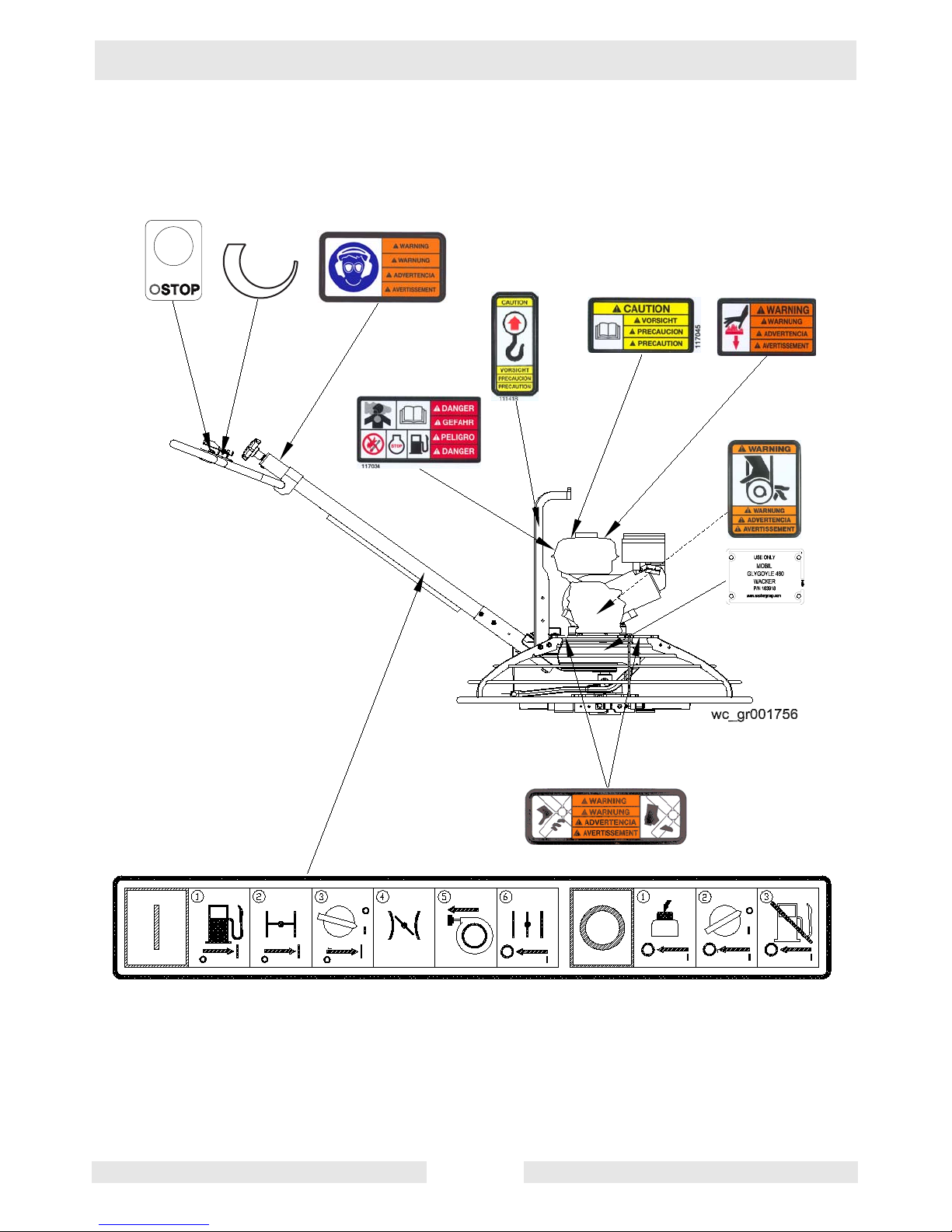
1.5 Label Locations
wc_si000139gb.fm 12
Page 13
CT 36 / CT 48 Safety Information
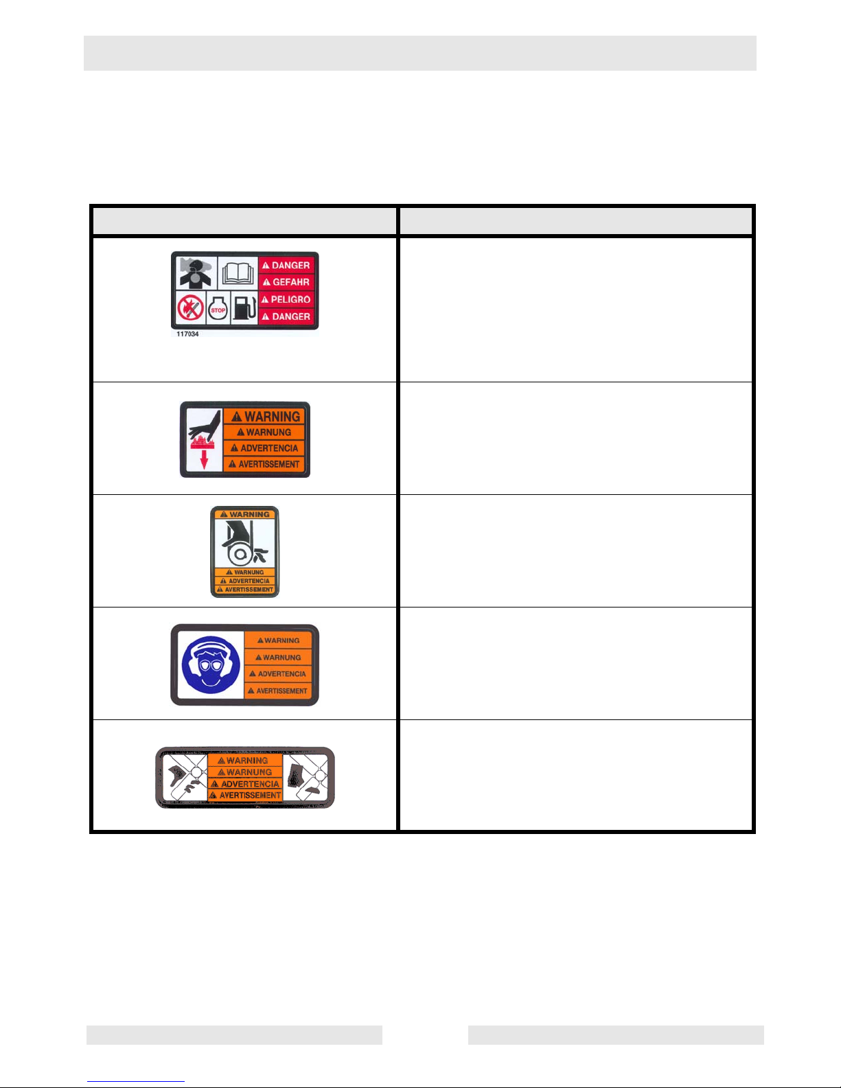
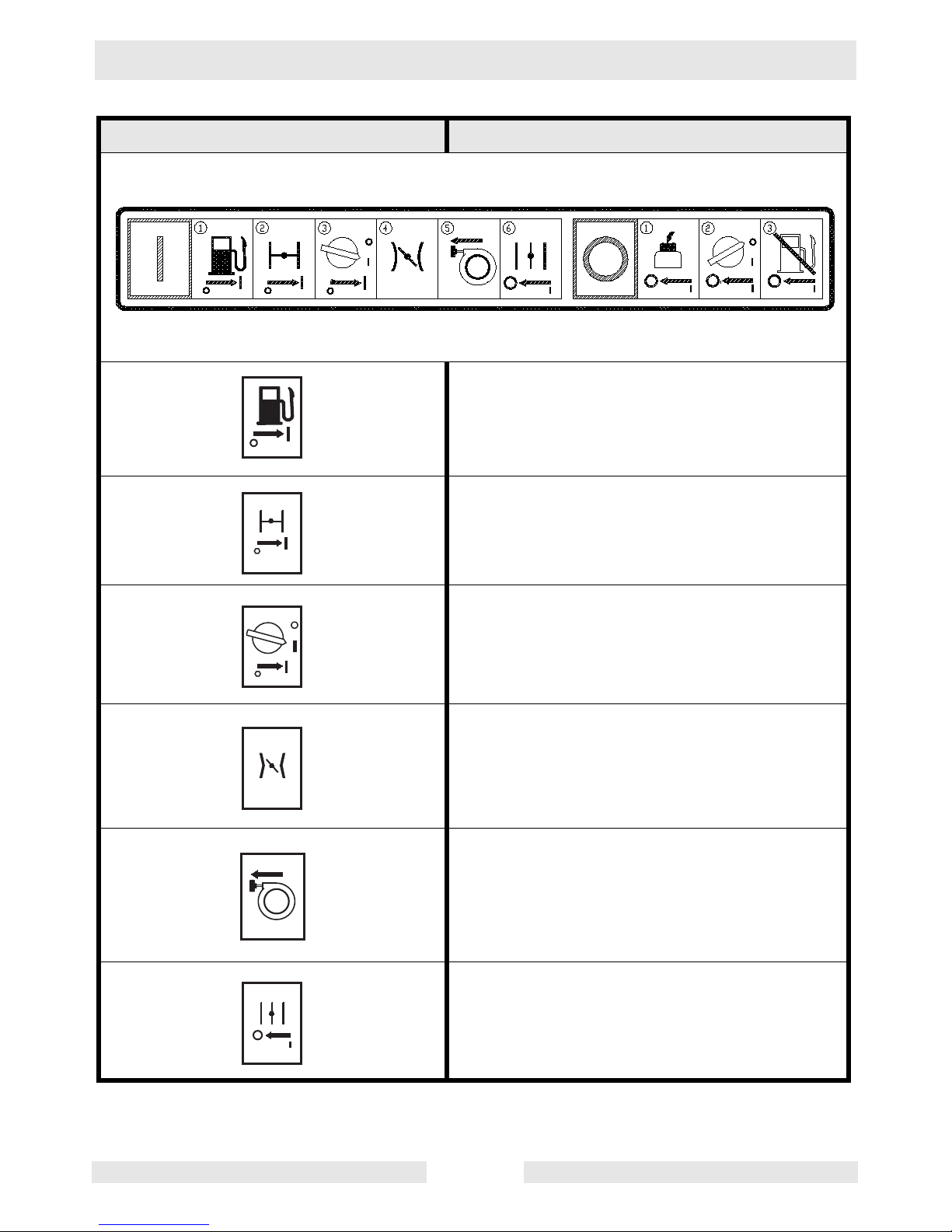
1.6 Safety and Information Labels
Wacker machines use international pictorial labels where needed.
These labels are described below:
Label Meaning
DANGER!
Engines emit carbon monoxide; operate only
in well-ventilated area. Read the Operator’s
Manual.
No sparks, flames, or burning objects near the
machine. Shut off the engine before refueling.
WARNING!
Hot surface!
WARNING!
Hand injury if caught in moving belt.
Always replace beltguard.
WARNING!
Always wear hearing and eye protection when
operating this machine.
WARNING!
Cutting hazard. Always replace blade guard!
wc_si000139gb.fm 13
Page 14
Safety Information CT 36 / CT 48
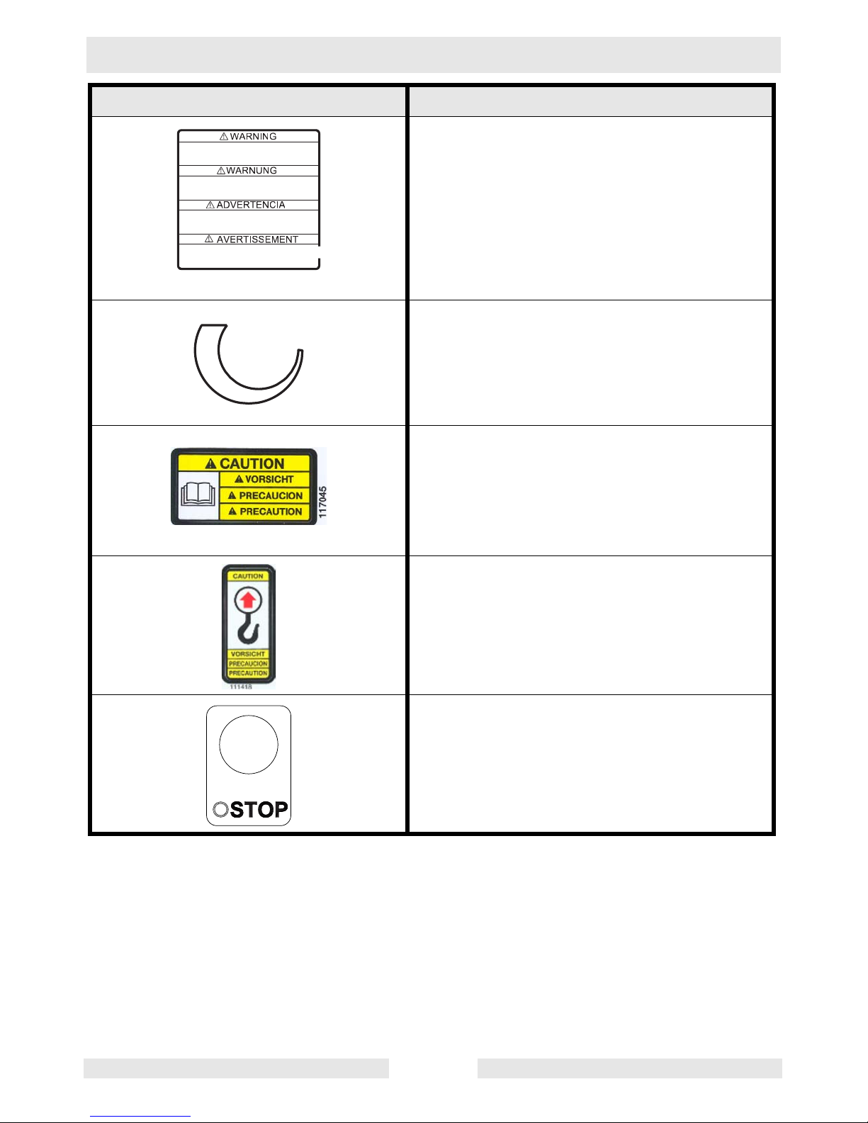
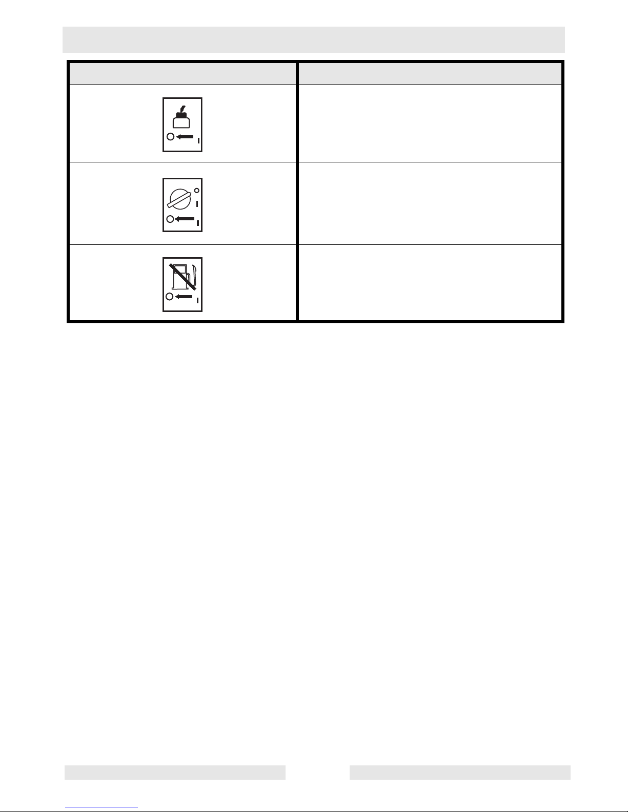
Label Meaning
R e m o v e p a n f r o m t r o w e l b e f o r e l i f t i n g m a c h i n e
o v e r h e a d .
P a n s c a n f a l l a n d c a u s e d e a t h o r s e r i o u s i n j u r y i f
a p e r s o n i s h i t .
G l e i t s c h e i b e v o m B e t o n g l ä t t e r e n t f e r n e n b e v o r
d a s G e r ä t u b e r K o p f h ö h e g e h o b e n w i r d .
G l e i t s c h e i b e k a n n f a l l e n u n d s c h w e r e V e r l e t z u n g
o d e r T o d v e r u r s a c h e n w e n n P e r s o n a l g e t r o f f e n w i r d .
Q u i t e e l d i s c o d e f l o t a c i ó n a n t e s d e l e v a n t a r l a
m á q u i n a a l i s a d o r a d e h o r m i g ó n .
L o s d i s c o s p o d r í a n c a e r y m a t a r o l a s t i m a r
s e r i a m e n t e a u n a p e r s o n a q u e s e e n c u e n t r e c e r c a .
A v a n t d e l e v e r l a p p a r e i l a u - d e s s u s d e v o t r e t ê t e ,
ô t e r l e d i s q u e d e t a l o c h a g e d e l a t r u e l l e .
L e d i s q u e d e t a l o c h a g e p e u t t o m b e r e t e n t r a î n e r
d e g r a v e s b l e s s u r e s o u m ê m e l a m o r t .
WARNING!
Remove pan from trowel before lifting machine
overhead. Pans can fall and cause death or
serious injury if a person is hit. (Located on top
side of float pan.)
1 1 8 6 8 8
Variable speed throttle
CAUTION!
Read and understand the supplied Operator’s
Manuals before operating this machine. Failure to do so increases the risk of injury to yourself or others.
CAUTION!
Lifting point.
Engine stop button:
Press to stop engine.
wc_si000139gb.fm 14
Page 15
CT 36 / CT 48 Safety Information
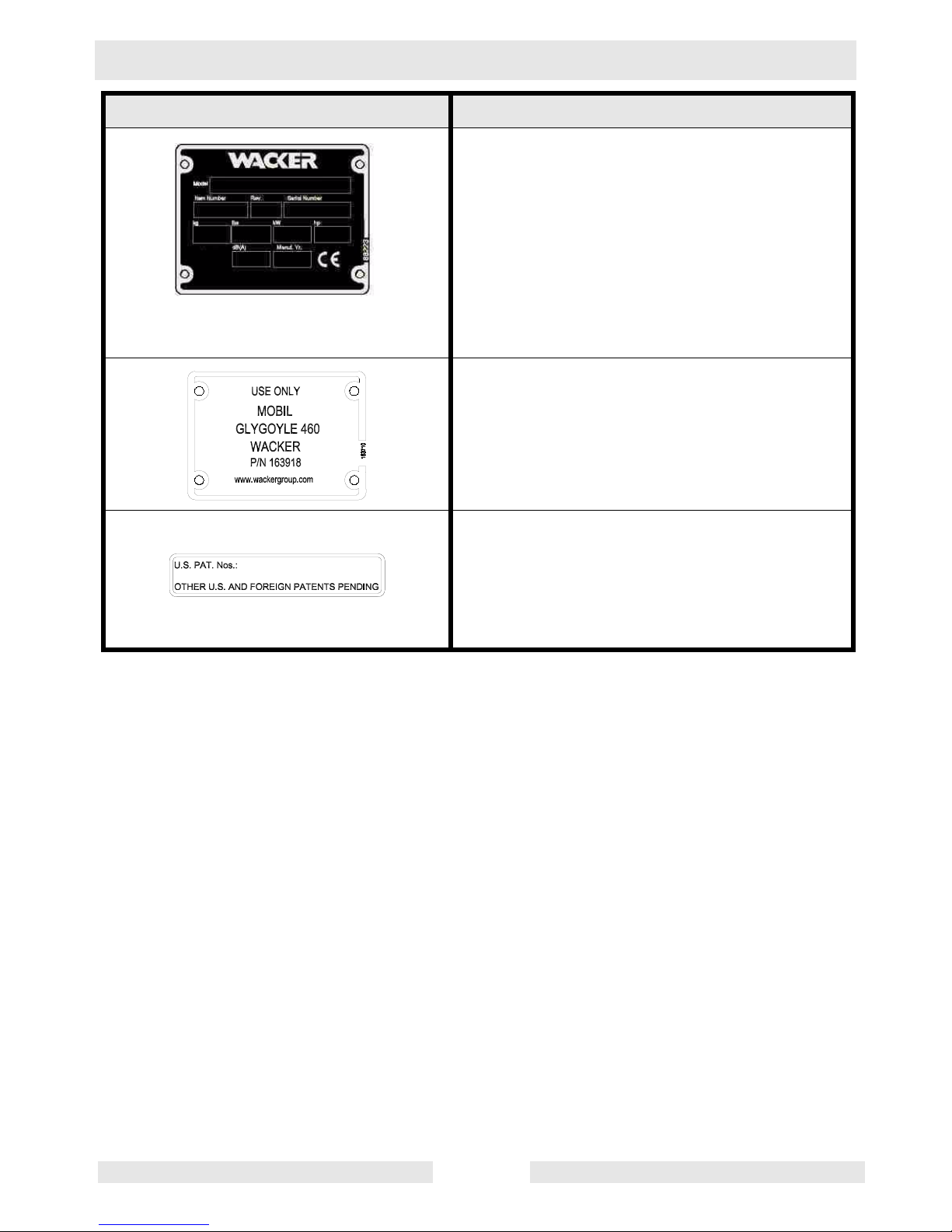
Label Meaning
A nameplate listing the model number, item
number, revision number, and serial number is
attached to each unit. Please record the information found on this plate so it will be available
should the nameplate become lost or damaged. When ordering parts or requesting service information, you will always be asked to
specify the model number, item number, revision number, and serial number of the unit.
Use only Glygoyle 460 gear oil in gearbox.
This machine may be covered by one or more
patents.
wc_si000139gb.fm 15
Page 16
Safety Information CT 36 / CT 48
Label Meaning
Open the fuel flow valve.
Close the choke.
Turn engine key switch to “ON” position.
Place throttle in the IDLE position.
Pull the rewind starter.
Open the choke.
wc_si000139gb.fm 16
Page 17
CT 36 / CT 48 Safety Information
Label Meaning
Press the stop button.
Turn engine key switch to “OFF” position.
Close the fuel flow valve.
wc_si000139gb.fm 17
Page 18
Technical Data CT 36 / CT 48
2. Technical Data
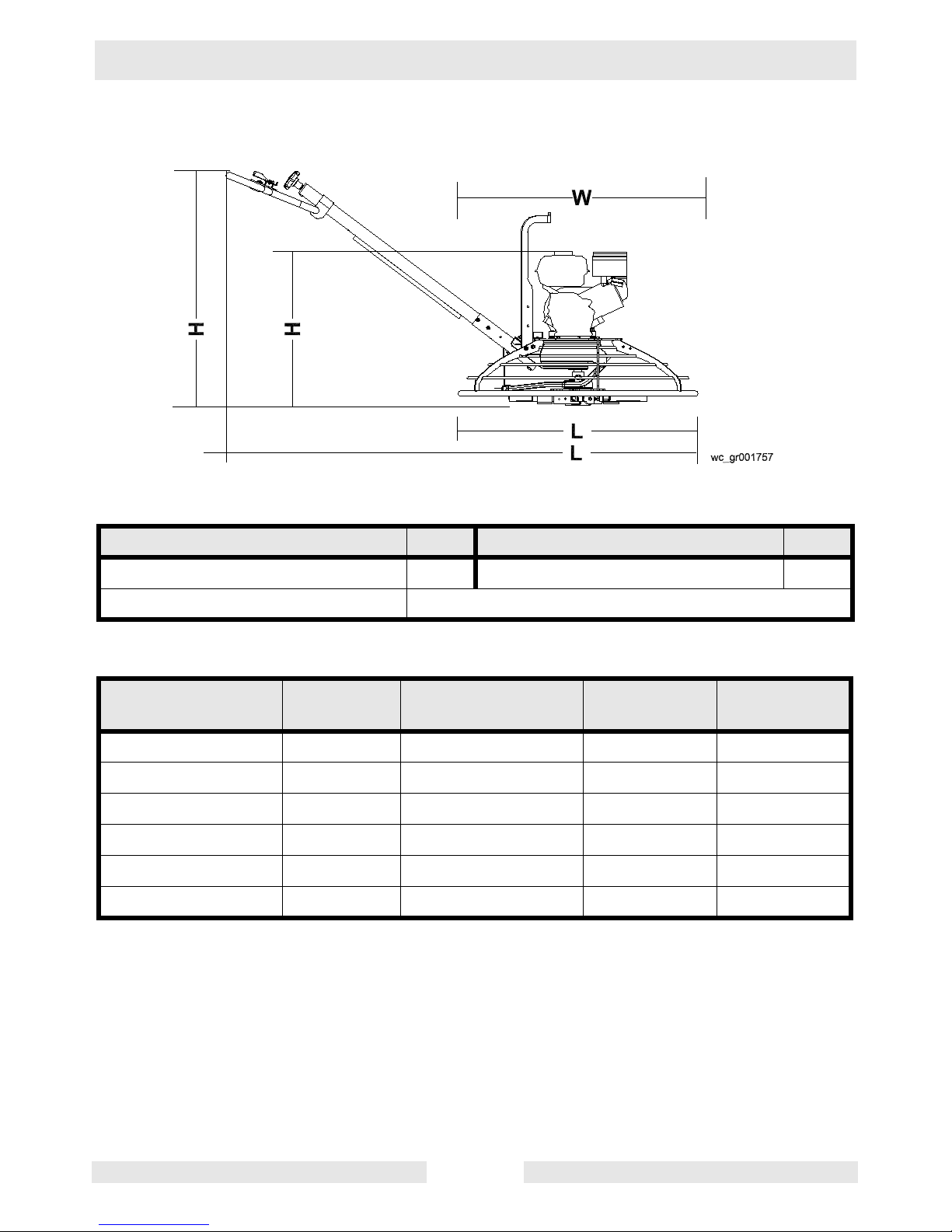
2.1 Dimensions and Weight
Guide
Description Ref. Description Ref.
Honda engine* A Variable Speed V
Engine Horse Power 4, 5, 6, 8, 9, 11, 13
*Standard models feature Wacker engine.
Handle Type Item No.
L
mm(in.)
Pitch
Type
Weight
kg (lbs.)
Solid 0159659 1740 (68.5) Twist 10 (21)
Folding 0159660 1740 (68.5) Twist 12 (26.5)
Adjustable/Folding 0164617 1740 (68.5) Twist 13 (28)
Adjustable 0164535 1740 (68.5) Twist 11 (24.5)
Adjustable/Folding 0159661 1740 (68.5) Pro-Shift® 15 (32.5)
Adjustable 0159662 1740 (68.5) Pro-Shift® 13 (29)
wc_td000141gb.fm 18
Page 19

CT 36 / CT 48 Technical Data
without handle with handle
Model Item No.
CT 36-5A
0009438
0620106
CT 36-6 0009443
CT 36-8A 0009439
CT 36-8A-V 0009442
CT 36-9 0009444
CT 36-9-V 0009447
CT 48-8A 0009449
CT 48-9 0009453
LxWxH
mm
(in.)
915x915x607
(36x36x24)
915x915x607
(36x36x24)
915x915x686
(36x36x27)
915x915x686
(36x36x27)
915x915x686
(36x36x27)
915x915x686
(36x36x27)
1220x1220x686
(48x48x27)
1220x1220x686
(48x48x27)
LxWxH
mm
(in.)
2005x915x1040
(79x36x41)
2005x915x1040
(79x36x41)
2005x915x1040
(79x36x41)
2005x915x1040
(79x36x41)
2005x915x1040
(79x36x41)
2005x915x1040
(79x36x41)
2160x1220x1040
(85x48x41)
2160x1220x1040
(85x48x41)
without
weight kit
kg (lbs.)
with
weight kit
kg (lbs.)
85 (183) 91 (201)
85 (183) 91 (201)
94 (208) 103 (226)
94 (208) 103 (226)
90 (199) 98 (217)
90 (199) 98 (217)
105 (234) 114 (252)
105 (234) 114 (252)
CT 48-11A 0009450
CT 48-13A-V 0009452
1220x1220x712
(48x48x28)
1220x1220x712
(48x48x28)
2160x1220x1040
(85x48x41)
2160x1220x1040
(85x48x41)
113 (250) 122 (268)
121 (268) 130 (286)
wc_td000141gb.fm 19
Page 20

Technical Data CT 36 / CT 48
2.2 Engine
Item No.
Engine Make
Engine Model
Rated Power
Spark Plug
Electrode Gap
Engine Speed - full load
Engine Speed - idle
Clutch engagement
Valve Clearance (cold)
intake:
exhaust:
Air Cleaner
Engine Lubrication
Engine Oil Capacity
Fuel
Fuel Tank Capacity
Fuel Consumption
Running time
kW (Hp)
mm (in.)
rpm
rpm
rpm
mm (in.)
type
oil grade
l (oz.)
type
l (qts.)
l (qts.)
/hr
hr.
CT 36-5A
0009438, 0620106
CT 36-6
0009443
Engine
Honda
GX 160 K1 QX2
4.3 (5.7) @ 3800rpm
NGK BPR 6ES NGK BR6HS
0.7 – 0.8 (0.028 – 0.031)
3800 ± 100
1450 ± 100
1800
0.15 (0.006)
0.20 (0.008)
Dual element
SAE 10W30 SG or SF SAE 10W30
0.6 (20)
Regular unleaded gasoline
3.6 (3.8)
1.8 (1.9) 1.52 (1.6)
22.4
4.2 (5.6) @ 3800 rpm
0.6–0.7 (0.024–0.028)
0.07–0.13 (0.0028–0.0051)
0.17–0.23 (0.0067–0.0091
Wacker
WM170
Champion RL86C
1400 ± 100
SE or higher
wc_td000141gb.fm 20
Page 21

CT 36 / CT 48 Technical Data
Item No.
Engine Make
Engine Model
Rated Power
Spark Plug
Electrode Gap
Engine Speed - full load
Engine Speed - idle
Clutch engagement
Valve Clearance (cold)
intake:
exhaust:
Air Cleaner
Engine Lubrication
Engine Oil Capacity
Fuel
Fuel Tank Capacity
Fuel Consumption
Running time
kW (Hp)
mm (in.)
rpm
rpm
rpm
mm (in.)
type
oil grade
l (oz.)
type
l (qts.)
l (qts.)
/hr
hr.
CT 36-8A
0009439
CT 36-8A-V
0009442
CT36-9
0009444
CT 36-9-V
0009447
Engine
Honda Wacker
GX 240 K1 QA WM270
6.2 (8.3) @ 3800 rpm 6.5 (8.7) @ 3800 rpm
NGK BPR 6ES
0.7 – 0.8 (0.028 – 0.031)
3800 ± 100
1450 ± 100 1400 ± 100
1800
0.15 (0.006)
0.20 (0.008)
Dual element
SAE 10W30 SG or SF
1.1 (37)
Regular unleaded gasoline
6.0 (6.4)
2.7 (2.8) 2.5 (2.6)
2.25 2.4
NGK BR6HS
Champion RL86C
0.07–0.13 (0.0028–0.0051)
0.17–0.23 (0.0067–0.0091
SAE 10W30
SF, SE, SD, or SC
wc_td000141gb.fm 21
Page 22

Technical Data CT 36 / CT 48
Item No.
Engine Make
Engine Model
Rated Power
Spark Plug
Electrode Gap
Engine Speed - full load
Engine Speed - idle
Clutch engagement
Valve Clearance (cold)
intake:
exhaust:
Air Cleaner
Engine Lubrication
Engine Oil Capacity
Fuel
Fuel Tank Capacity
Fuel Consumption
Running time
kW (Hp)
mm (in.)
rpm
rpm
rpm
mm (in.)
type
oil grade
l (oz.)
type
l (qts.)
l (qts.)
/hr
hr.
CT 48A-8A
0009449
CT 48-9
0009453
Engine
Honda Wacker
GX 240 K1 QA WM270
6.2 (8.3) @ 3800 rpm 6.5 (8.7) @ 3800 rpm
NGK BPR 6ES
0.7 – 0.8 (0.028 – 0.031)
3800 ± 100
1450 ± 100 1400 ± 100
1800
0.15 (0.006)
0.20 (0.008)
Dual element
SAE 10W30 SG or SF
1.1 (37)
Regular unleaded gasoline
6.0 (6.4)
2.7 (2.8) 2.5 (2.6)
2.25 2.4
NGK BR6HS
Champion RL86C
0.07–0.13 (0.0028–0.0051)
0.17–0.23 (0.0067–0.0091
SAE 10W30
SF, SE, SD, or SC
wc_td000141gb.fm 22
Page 23

CT 36 / CT 48 Technical Data
Item No.
Engine Make
Engine Model
Rated Power
Spark Plug
Electrode Gap
Engine Speed - full load
Engine Speed - idle
Clutch engagement
Valve Clearance (cold)
intake:
exhaust:
Air Cleaner
Engine Lubrication
Engine Oil Capacity
Fuel
Fuel Tank Capacity
Fuel Consumption
Running time
kW (Hp)
mm (in.)
rpm
rpm
rpm
mm (in.)
type
oil grade
l (oz.)
type
l (qts.)
l (qts.)
/hr
hr.
CT 48-11A
0009450
CT 48-13A-V
0009452
Engine
Honda
GX 340 K1 QA GX 390 U1 QA
8.7 (11.6) @ 3800 rpm 10 (13.4) @ 3800 rpm
NGK BPR 6ES
0.7 – 0.8 (0.028 – 0.031)
3800 ± 100
1450 ± 100
1800
0.15 (0.006)
0.20 (0.008)
Dual element
SAE 10W30
SG or SF
1.1 (37)
Regular unleaded gasoline
6.0 (6.4)
2.7 (2.8)
2.25
wc_td000141gb.fm 23
Page 24

Technical Data CT 36 / CT 48
2.3 Trowel
Model Item No.
Trowel
Diameter*
mm (in.)
Number
of
Blades
Gear Box
Lubrication
type/ml (oz.)
Speed
Range
rpm
Trowel
CT 36-5A
0009438
0620106
60–125
CT 36-6 0009443
CT 36-8A 0009439 60–125
CT 36-8A-V 0009442 25–200
CT 36-9 0009444 60–125
CT 36-9-V 0009447 25–200
CT 48-8A 0009449
915 (36)
Mobil
Glygoyle
4
460
Approx.
620 (21)
60–125CT 48-9 0009453
1220 (48)
CT 48-11A 0009450
CT 48-13A-V 0009452 25–200
*Trowel blades must NOT be interchanged, i.e., do NOT put larger diameter blades on a smaller
diameter trowel.
Pitch
Range
degrees
0–30
wc_td000141gb.fm 24
Page 25

CT 36 / CT 48 Technical Data
2.4 Sound and Vibration Data
The required sound specification, Paragraph 1.7.4.f of 89/392/EEC
Machinery Directive, is:
• the sound pressure level at operator’s location (L
• the guaranteed sound power level (L
) = “B” dB(A)
WA
) : “A” dB(A)
pA
These sound values were determined according to ISO 3744 for the
sound power level (LWA) and ISO 6081 for the sound pressure level
(LpA) at the operator’s location.
• The weighted effective acceleration value, determined according to
ISO 8662 Part 1, is: “C” m/s2.
The sound and vibration specifications were obtained with the unit
operating on wetted and cured concrete at full engine speed.
Model Item No. A B C
CT 36-5A
0009438
0620106
103 89 5.3
CT 36-6 0009443 103 89 5.3
CT 36-8A 0009439 109 95 4.3
CT 36-8A-V 0009442 109 95 4.0
CT 36-9 0009444 109 95 7.1
CT 36-9-V 0009447 109 95 6.6
CT 48-8A 0009449 109 95 5.3
CT 48-9 0009453 109 95 5.3
CT 48-11A 0009450 113 96 7.1
CT 48-13A-V 0009452 115 98 4.1
wc_td000141gb.fm 25
Page 26

Operation CT 36 / CT 48
3. Operation
3.1 Application
This trowel is a modern, high production machine intended for floating
and finishing freshly poured concrete slabs. The machine's good
balance, adjustable handle, and easily reached controls add to
operator comfort and productivity. An automatic stop sensor provides
added operator safety. Finishing rates will depend on operator skill and
job conditions.
DO NOT use this machine for any application other than troweling
concrete.
3.2 New Machine Set-up
Trowels are shipped from the factory with the handle removed. Follow
instructions on Installing Blades and Installing and Adjusting Handles
when setting up new machines or when installing new handles and
blades.
3.3 Recommended Fuel
The engine requires regular grade unleaded gasoline. Use only fresh,
clean gasoline. Gasoline containing water or dirt will damage fuel
system. Consult engine Owner’s Manual for complete fuel
specifications.
wc_tx000373gb.fm 26
Page 27
CT 36 / CT 48 Operation
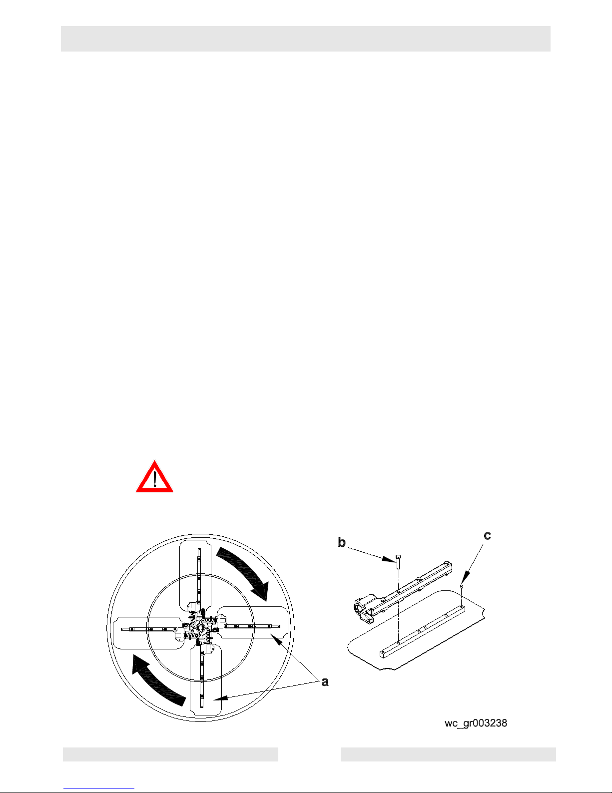
3.4 Installing Blades
See Graphic: wc_gr003238
There are four types of blades available for the trowels. Float pans are
large "pizza pan" style blades, which hook on over finish or
combination blades and are available for the 36" machines only. Float
blades are available for all machines and clip on over finish or
combination blades. Both are used in the earliest stages of work, and
are not pitched.
Finish blades are used in the final stages of working, and are
progressively pitched to burnish the concrete.
Combination blades can be used throughout the concrete working
process. They are used in place of float blades or pans and finish
blades.
Note: Trowel blades must NOT be interchanged, i.e., do NOT put
larger diameter blades on a smaller diameter trowel.
3.4.1 Finish blades are flat on both edges and can be installed in either
direction.
When installing combination blades, orient blades as shown (a). This
positions the raised edges of the blade correctly for the clockwise
rotation of the machine.
3.4.2 Secure blades to trowel arms with screws (b). Dip threads of screws in
grease prior to installation. This will prevent concrete from cementing
the screws in place and will make removal of the blades easier later on.
3.4.3 Plug the remaining threaded holes in the blade brace with plastic plugs
(c) to prevent them from filling with concrete.
Do not lift the trowel overhead with a float pan attached, as the pan
could fall off and strike personnel working in the vicinity.
WARNING
wc_tx000373gb.fm 27
Page 28

Operation CT 36 / CT 48
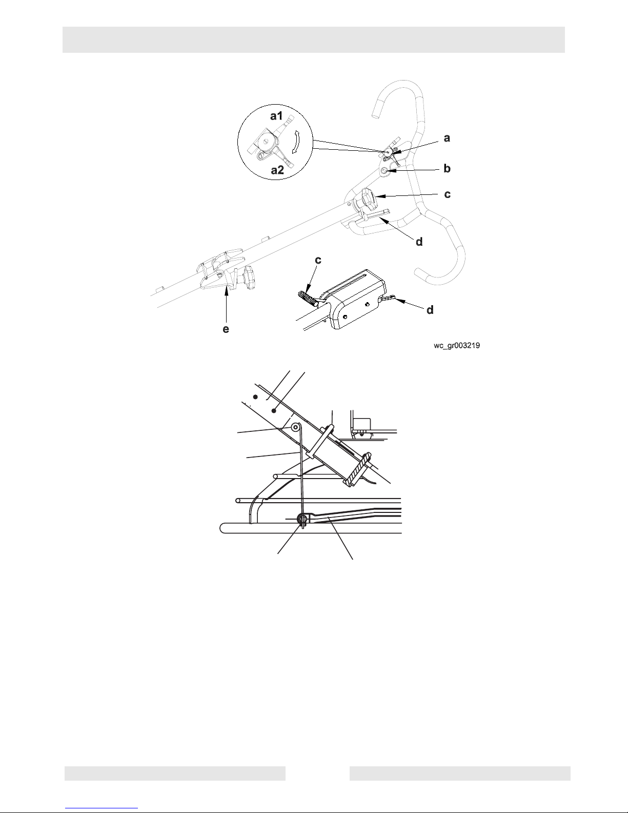
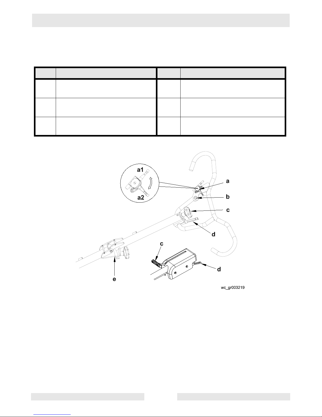
3.5 Installing and Adjusting Handles
See Graphic: wc_gr001758, wc_gr003219
On new machines the pipe handle comes assembled with the pitch
control (Twist or Pro-Shift®) (c), stop button (b), throttle (a), screws
(g), and nut (m).
To install the pipe handle assembly:
3.5.1 On machines with the foldable handle, straighten the handle and
tighten the knob (e) to secure the handle in position.
3.5.2 Pull the pitch control cable (j) from bottom end of the tube and remove
the nut from the cable.
3.5.3 Thread the cable through the handle base (f) and over the pulley (h)
as shown.
3.5.4 Attach the pipe handle to the handle base with two M8x65 screws (g).
Torque the screws to 25 Nm (18 ft.lbs.).
3.5.5 Push the Pro-Shift® handle all the way forward (away from the
operator) OR turn the twist pitch control handle counterclockwise as far
as possible. Connect the cable to the fork (k) as shown and adjust the
cable nut (m) so the cable is snug and the trowel blades lay flat (0°
pitch).
3.5.6 Move throttle (a1) to idle position. Remove air cleaner cover. Feed
cable through clamp on recoil cover. Connect throttle cable to engine
throttle bracket by placing z-bend through hole in throttle plate. Clamp
cable into throttle casing bracket. Replace air cleaner cover.
3.5.7 Connect electrical wire on handle to both ends of the engine wire. See
handle instruction sheet for additional detail on installation.
Note: On machines with Wacker engines, do not connect wires in bag
to wires in handle.
3.5.8 On machines with an adjustable handle, position the handle by
loosening the knob (d) and adjusting the handle up or down to suit the
operator. Tighten the knob to secure the handle in position.
wc_tx000373gb.fm 28
Page 29
CT 36 / CT 48 Operation
e
f
g
h
wc_gr001758
k
j
wc_tx000373gb.fm 29
Page 30
Operation CT 36 / CT 48
3.6 Controls
See Graphic: wc_gr003219
Ref. Description Ref. Description
a Throttle lever d Handle height adjustment (if
equipped)
b Stop button e Foldable handle adjustment (if
equipped)
c Twist pitch control or Pro-Shift®
pitch control
wc_tx000373gb.fm 30
Page 31

CT 36 / CT 48 Operation
3.7 Stop Button
See Graphic: wc_gr003219
When the stop button (b) is pressed, the engine will shut off.
To prevent uncontrolled spinning of the trowel, the engine control
module is designed to shutoff the engine under certain conditions. For
example, if the operator loses his/her grip on the trowel, the engine
control module will sense that the machine is spinning and shut off the
engine. The momentum of the spinning trowel will engage the brake
and stop the handle from spinning past 270°.
3.8 Before Starting
Before starting trowel, check the following:
• oil level in engine
• oil level in gearbox
• fuel level
• condition of air filter
• condition of fuel lines
• condition of trowel arms and blades
• condition of ring guard
• label descriptions
• handle height to suit operator
wc_tx000373gb.fm 31
Page 32

Operation CT 36 / CT 48
3.9 To Start - Honda
See Graphic: wc_gr003219, wc_gr001098
3.9.1 Open fuel valve by moving lever to the right (g1).
Note: If engine is cold, move choke lever to closed position (i1). If
engine is hot, set choke to open position (i2).
3.9.2 Turn engine switch to “ON” (h1).
3.9.3 Move the throttle lever to the idle position (a1).
Note: Start engine with throttle in the idle position. If the engine is
started when the throttle is not in the idle position, the engine should
not start. This is a feature of the engine control module that prevents
wide open throttle startup.
3.9.4 Pull starter rope (j).
Do not place foot on the ring guard when starting the engine, as severe
injury can occur if foot slips through the ring guard as the blades start
WARNING
to spin.
Note: If the engine oil is low, the engine will not start. If engine does
not start, check the oil level and add oil as needed.
3.9.5 Open choke as engine warms (i2).
3.9.6 Open throttle (a2) to operate trowel. Adjust blade RPM with throttle
speed to suit conditions.
wc_tx000373gb.fm 32
Page 33

CT 36 / CT 48 Operation
g1
g2
3.10 To Stop - Honda
See Graphic: wc_gr003219, wc_gr001098
3.10.1 Reduce engine RPM to idle by moving the throttle lever to idle position
(a1).
3.10.2 Push the stop button (b).
3.10.3 Turn engine switch to “OFF” (h2).
3.10.4 Close fuel valve by moving lever to the left (g2).
h2
h1
i1
i2
j
wc_gr001098
wc_tx000373gb.fm 33
Page 34

Operation CT 36 / CT 48
3.11 To Start - Wacker
See Graphic: wc_gr003219, wc_gr002747
3.11.1 Open fuel valve by moving lever down (g1).
Note: If engine is cold, move choke lever to close position (i2). If
engine is hot, set choke to open position (i1).
3.11.2 Turn engine switch to “ON” (h2).
3.11.3 Move the throttle lever to the idle position (a1).
Note: Start engine with throttle in the idle position. If the engine is
started when the throttle is not in the idle position, the engine should
not start. This is a feature of the engine control module that prevents
wide open throttle startup.
3.11.4 Pull starter rope (j).
Do not place foot on the ring guard when starting the engine, as severe
injury can occur if foot slips through the ring guard as the blades start
WARNING
to spin.
Note: If the engine oil is low, the engine will not start. If engine does
not start, check the oil level and add oil as needed.
3.11.5 Open choke as engine warms (i1).
3.11.6 Open throttle (a2) to operate trowel. Adjust blade RPM with throttle
speed to suit conditions.
wc_tx000373gb.fm 34
Page 35

CT 36 / CT 48 Operation
g2
g1
h2
h1
3.12 To Stop - Wacker
See Graphic:wc_gr003219, wc_gr002747
3.12.1 Reduce engine RPM to idle by moving the throttle lever to idle position
(a1).
3.12.2 Push the stop button (b).
3.12.3 Turn engine switch to “OFF” (h1).
3.12.4 Close fuel valve (g2).
i1
i2
j
wc_gr002747
wc_tx000373gb.fm 35
Page 36

Operation CT 36 / CT 48
3.13 Engine Control Module
To prevent uncontrolled spinning of the trowel, the engine control
module is designed to shutoff the engine under certain conditions. For
example, if the operator loses his/her grip on the trowel, the engine
control module will sense that the machine is spinning and shut off the
engine. The momentum of the spinning trowel will engage the brake
and stop the handle from spinning past 270°.
To test the engine control module, start the machine and jerk the
handle to the right. The engine should stop. If the engine does not stop,
repeat the jerking motion until the engine stops. If the engine does not
shut off, push the stop button and turn the engine off. DO NOT operate
the machine until the engine control module is replaced.
DO NOT operate the trowel if the engine control module is
disconnected or not functioning properly.
WARNING
3.14 Operation
See Graphic: wc_gr003239
ALWAYS test the function of the engine control module before
operating the trowel. DO NOT operate the trowel if the engine control
WARNING
3.14.1 Adjust handle height to suit operator. See Installing and Adjusting
module is not functioning properly.
Choose correct blade type and attach blades to trowel arms. Do not
mix float or finish blades with combination blades.
Note: When operating on soft concrete, do not let trowel stand in one
spot too long. Always lift trowel from slab when operation is complete.
Note: “Left” and “Right” references are made from the operator's
position.
Handles.
NOTICE: Do not attempt to adjust handle height on the trowel while it
is running.
3.14.2 Start engine and engage blades by increasing engine speed. Set
speed with throttle control on handle bar to appropriate speed for job
conditions.
3.14.3 To move trowel forward twist handle clockwise (a).
3.14.4 To move backward twist handle counterclockwise (b).
3.14.5 To move to the left lift up slightly on the handle (c).
wc_tx000373gb.fm 36
Page 37

CT 36 / CT 48 Operation
3.14.6 To move to the right press down slightly on the handle (d).
3.14.7 Clean trowel after each use to remove concrete splatter.
Allow the muffler to cool before cleaning or servicing the machine. A
hot muffler could ignite the fuel and start a fire.
WARNING
It is recommended that each set of work passes be at 90° to the
previous set of work passes. This will help prevent the creation of
valleys in the slab surface.
For example, in the illustration, the second set of work passes (2) is
90° to the first set of work passes (1).
Personnel other than the trowel operator should not be allowed in the
work area, as severe injury can occur from contact with operating
WARNING
trowel blades.
Do not attempt to clean, service or perform adjustments on the trowel
while it is running.
a
1
c
d
2
b
wc_gr003239
wc_tx000373gb.fm 37
Page 38

Operation CT 36 / CT 48
3.15 Braking System
The braking system of the trowel is spring loaded. The brake is
engaged anytime the input shaft of the gearbox is not rotating and/or
there is no resistance placed against the blades of the trowel. The
brake is released when the input shaft is rotated and is shifted out from
its seated position. This is accomplished when the gear on this shaft
rotates, working against the output shaft gear, forcing the shaft out. If
there is no or low resistance against the blades, the brake may not
release as it is the resistance against the blades that allows the brake
to release. If the machine is suspended or on a highly polished,
slippery surface, the brake will not release and could cause belt
slippage.
wc_tx000373gb.fm 38
Page 39

CT 36 / CT 48 Operation
3.16 Pitch Adjustment
See Graphic: wc_gr003220
To adjust blade pitch (angle):
A = Twist pitch: turn the pitch adjusting knob (a) clockwise to increase
pitch and counterclockwise to decrease pitch.
B = Pro-Shift®: pull the handle (b) towards the operator to increase
pitch and away from the operator to decrease pitch.
AB
a
b
C
1
D
2
5˚
3
10˚
4
15-30˚
Ref. C = Working condition of concrete D = Suggested working pitch
wc_gr003220
1 Wet surface working stage Flat (no pitch)
2 Wet to plastic working stage Slight pitch (5°)
3 Plastic working stage Additional pitch (10°)
4 Semi-hard working stage to hard
finishing stage (burnishing)
For final finishing stages, it is sometimes desirable to add weights to the trowel guard rings to
increase the burnishing force. Wacker supplies weight kits for this purpose.
wc_tx000373gb.fm 39
Maximum pitch (15-30°)
Page 40

Maintenance CT 36 / CT 48
4. Maintenance
4.1 Periodic Maintenance Schedule - Honda
The chart below lists basic machine and engine maintenance. Refer to
the engine manufacturer’s Operator’s Manual for additional
information on engine maintenance.
Check fuel level.
Check engine oil level.
Inspect fuel lines.
Inspect air filter. Replace as needed.
Check external hardware.
Clean trowel after each use to remove
concrete splatter.
Grease blade arms as needed.
Clean air cleaner elements.
Change engine oil.
Check drive belt.
Clean sediment cup.
Daily
After
first
20 hrs.
Every
50
hrs.
Every
100
hrs.
Every
300
hrs.
Check and clean spark plug.
Check and adjust valve clearances.
wc_tx000374gb.fm 40
Page 41

CT 36 / CT 48 Maintenance
4.2 Periodic Maintenance Schedule - Wacker
The chart below lists basic machine and engine maintenance. Refer to
the engine manufacturer’s Operator’s Manual for additional
information on engine maintenance.
Daily After
first 20
hours
Check fuel level.
Check engine oil level.
Inspect fuel lines.
Inspect air filter. Replace as
needed.
Check external hardware.
Clean trowel after each use to
remove concrete splatter.
Change engine oil. *
Grease blade arms as needed
Clean air cleaner elements.
Clean sediment cup / fuel filter.
Every
2 weeks
or
50 hrs.
Every
month
or
100 hrs.
Every
year
or
300 hrs.
Every
500 hrs.
Check and clean spark plug.
Check and adjust valve clearance.
Replace spark plug.
* Perform initially after first 20 hours of operation.
Maintenance, replacement or repair of emission control devices and systems may be performed by
any repair establishment or individual.
wc_tx000374gb.fm 41
Page 42

Maintenance CT 36 / CT 48
4.3 Engine Oil - Honda
See Graphic: wc_gr002381
4.3.1 Drain oil while the engine is still warm.
4.3.2 Remove the oil fill plug (a) and drain cap (b) to drain oil.
Note: In the interests of environmental protection, place a plastic sheet
and a container under the machine to collect any liquid which drains
off. Dispose of this liquid in accordance with environmental protection
legislation.
4.3.3 Install drain cap.
4.3.4 Fill the engine crankcase with recommended oil up to the level of the
plug opening (c). See Technical Data for oil quantity and type.
4.3.5 Install the oil filler plug.
wc_tx000374gb.fm 42
Page 43

CT 36 / CT 48 Maintenance
4.4 Engine Oil - Wacker
See Graphic: wc_gr003201
4.4.1 Drain oil while engine is still warm.
Note: In the interests of environmental protection, place a plastic sheet
and a container under the machine to collect any liquid which drains
off. Dispose of this liquid in accordance with environmental protection
legislation.
4.4.2 Remove the oil drain cap (a).
4.4.3 Allow the oil to drain.
4.4.4 Install the drain cap.
4.4.5 Fill the engine crankcase through the oil filler opening (b), to the upper
mark on the dipstick (c). Do not thread in the dipstick to check the level.
See Technical Data for oil quantity and type.
4.4.6 When the crankcase is full, reinstall the dipstick.
c
a
b
wc_gr003201
wc_tx000374gb.fm 43
Page 44

Maintenance CT 36 / CT 48
4.5 Air Cleaner - Honda
See Graphic: wc_gr000025
The engine is equipped with a dual element air cleaner. Service air
cleaner frequently to prevent carburetor malfunction.
NOTICE: NEVER run engine without air cleaner. Severe engine
damage will occur.
NEVER use gasoline or other types of low flash point solvents for
cleaning the air cleaner. A fire or explosion could result.
WARNING
To service:
4.5.1 Remove air cleaner cover (a). Remove both elements and inspect
them for holes or tears. Replace damaged elements.
4.5.2 Wash foam element (b) in solution of mild detergent and warm water.
Rinse thoroughly in clean water. Allow element to dry thoroughly. Soak
element in clean engine oil and squeeze out excess oil.
4.5.3 Tap paper element (c) lightly to remove excess dirt. Replace paper
element if it appears heavily soiled.
wc_tx000374gb.fm 44
Page 45

CT 36 / CT 48 Maintenance
4.6 Air Cleaner - Wacker
See Graphic: wc_gr000656
NEVER use gasoline or other types of low flash point solvents for
cleaning the air cleaner. A fire or explosion could result.
WARNING
NOTICE: NEVER run engine without air cleaner. Severe engine
damage will occur.
The engine is equipped with a dual element air cleaner. Under normal
operating conditions, elements should be cleaned once every week.
Under severe, dry and dusty conditions, the elements should be
maintained daily. Replace an element when saturated with dirt that
cannot be removed.
4.6.1 Remove the air cleaner cover (a). Remove the filter assembly by
pulling it straight up. Inspect both elements for holes or tears. Replace
damaged elements.
4.6.2 Wash the foam element (b) in a solution of mild detergent and warm
water. Rinse it thoroughly in clean water. Allow the element to dry
thoroughly.
4.6.3 Tap the paper element (c) lightly to remove excess dirt or blow
compressed air through the filter from the inside out. Replace the
paper element if it appears heavily soiled.
a
b
c
wc_gr000656
wc_tx000374gb.fm 45
Page 46

Maintenance CT 36 / CT 48
4.7 Spark Plug
See Graphic: wc_gr000028
Clean or replace the spark plug as needed to ensure proper operation.
Refer to the engine owner’s manual.
The muffler becomes very hot during operation and remains hot for a
while after stopping the engine. Do not touch the muffler while it is hot.
WARNING
Note: Refer to the Technical Data for the recommended spark plug
type and the electrode gap setting.
4.7.1 Remove the spark plug and inspect it.
4.7.2 Replace the spark plug if the insulator is cracked or chipped.
4.7.3 Clean the spark plug electrodes with a wire brush.
4.7.4 Set the electrode gap (a).
4.7.5 Tighten the spark plug securely.
NOTICE: A loose spark plug can become very hot and may cause
engine damage.
wc_tx000374gb.fm 46
Page 47

CT 36 / CT 48 Maintenance
4.8 Cleaning Sediment Cup - Honda
See Graphic: wc_gr000029
4.8.1 Turn the fuel valve off.
4.8.2 Remove the sediment cup (a) and the O-ring (b).
4.8.3 Wash both thoroughly in a nonflammable solvent. Dry and reinstall
them.
4.8.4 Turn the fuel valve on and check for leaks.
b
a
wc_gr000029
4.9 Cleaning Fuel Strainer - Wacker
See Graphic: wc_gr001093
4.9.1 To remove water and dirt, close the fuel lever and remove the fuel
strainer.
4.9.2 Inspect the fuel strainer (a) for water and dirt.
4.9.3 After removing any dirt and water, wash the fuel cup with a
nonflammable solvent.
4.9.4 Reinstall securely to prevent leakage.
wc_tx000374gb.fm 47
Page 48

Maintenance CT 36 / CT 48
4.10 Adjusting Idle Speed - Honda
See Graphic: wc_gr001122
Remove the drive belt before making any adjustment to the carburetor.
See Belt Replacement. The blades will engage unless the belt is
WARNING
4.10.1 Start the engine and allow it to warm up to normal operating
4.10.2 Turn the throttle stop screw (a) in to increase speed, out to decrease
removed from the machine.
Adjust engine to the no load or idle speed per the Technical Data.
temperature.
speed. Make sure the throttle lever is touching the stop screw before
measuring rpm.
a
wc_gr001122
wc_tx000374gb.fm 48
Page 49

CT 36 / CT 48 Maintenance
4.11 Carburetor Adjustment - Honda
See Graphic: wc_gr0001061
Remove the drive belt before making any adjustment to the carburetor.
See Belt Replacement. The blades will engage unless the belt is
WARNING
removed from the machine.
The pilot screw (a) is fitted with a limiter cap to prevent excessive
enrichment of the air-fuel mixture in order to comply with emission
regulations. The mixture is set at the factory and no adjustment should
be necessary. Do not attempt to remove the limiter cap. The limiter cap
cannot be removed without breaking the pilot screw.
a
wc_gr001061
wc_tx000374gb.fm 49
Page 50

Maintenance CT 36 / CT 48
4.12 Belt Replacement
See Graphic: wc_gr002380, wc_gr003221
The trowel is equipped with a self-adjusting clutch. This clutch
automatically tightens the belt and compensates for belt wear. Replace
the belt if the clutch can no longer tighten belt enough to engage
gearbox without slipping.
To replace the drive belt:
4.12.1 Disconnect the spark plug lead.
To avoid accidental starting of the engine, always disconnect the spark
plug lead before working on machine.
WARNING
4.12.2 Loosen the screws (d) and remove the belt guard (c).
4.12.3 Slowly turn the pulley (b) and roll the belt (a) off.
Note: The clutch and the pulley are aligned at the factory and neither
should be removed during belt replacement.
4.12.4 Install the new belt.
4.12.5 Reattach the belt guard with washers and screws. Torque the screws
to 5 Nm (3.7 ft.lbs.).
wc_tx000374gb.fm 50
Page 51

CT 36 / CT 48 Maintenance
4.13 Trowel Lubrication
See Graphic: wc_gr001755
Grease trowel arms (b) with Shell Alvania RL2 grease or equivalent.
Oil the pitch control cable and other parts of trowel on an as needed
basis.
Oil in the gearbox should not require replacement unless it was
drained to service gearbox. Check quantity through plug (a) located on
side of gearbox. Oil level should be to bottom of the plug threads. See
Technical Data for oil quantity and type.
4.14 Optional Weights
To install optional weights, place equal number of weights in both front
and rear of guard ring in designated area. Tighten screw to keep
weights in place.
Under no circumstances should any object be used as additional
weight other than the weights recommended by Wacker. The use of
WARNING
wc_tx000374gb.fm 51
unauthorized weights could lead to personal injury or machine
damage.
Page 52

Maintenance CT 36 / CT 48
4.15 Lifting
See Graphic: wc_gr001762
NEVER lift the machine solely by the handle. The component may fail,
causing the machine to fall, possibly injuring bystanders.
WARNING
See Technical Data for the weight of the machine.
To lift the machine manually:
4.15.1 Stop engine.
4.15.2 Obtain a partner and plan the lift.
4.15.3 Balance the weight between the partners and lift the machine by the
guard ring (a), or proceed as follows:
a. Attach optional lifting bracket (c) to trowel with screws and locknuts.
Torque screws to 25 Nm (18 ft.lbs.).
b. Insert a 2x4 or other suitable lumber into the bracket. The lumber
must be long enough to extend past the ring guard.
c. Balance the weight between the partners and lift the machine by the
handle and the lumber.
To reduce risk of back injury while lifting, keep your feet flat on ground
and shoulder width apart. Keep your head up and back straight.
WARNING
To lift the machine mechanically:
4.15.4 Stop engine.
4.15.5 See Dimensions and Weight for weight of machine and be sure that
lifting device(s) can safely lift the weight.
4.15.6 Attach optional lifting bracket (b) to trowel with screws and locknuts.
Torque to 25 Nm (18 ft.lbs.).
4.15.7 Attach hook, harness, or cable to the lifting bracket on machine as
shown and lift as desired.
Do not lift the trowel overhead with a float pan attached, as the pan
could fall off and strike personnel working in the vicinity.
WARNING
wc_tx000374gb.fm 52
Page 53

CT 36 / CT 48 Maintenance
wc_tx000374gb.fm 53
Page 54

Maintenance CT 36 / CT 48
4.16 Storage
If trowel is being stored for more than 30 days:
• Change engine oil.
• Drain fuel from engine.
• Remove spark plug and pour 15 ml (½ ounce) of SAE 30 engine
oil into the cylinder. Replace spark plug and crank engine to
distribute oil. Refer to engine manual.
• Clean dirt from cylinder, cylinder head fins, blower housing,
rotating screen, and muffler areas.
• To save space, place handle in its storage position.
• Cover trowel and engine and store in a clean, dry area.
wc_tx000374gb.fm 54
Page 55

CT 36 / CT 48 Maintenance
4.17 Troubleshooting
Problem / Symptom Reason / Remedy
Trowel does not develop full
speed.
Engine runs;
poor trowel operation.
Engine does not start or runs
erratically.
• Remove deposits built up in engine cylinder and
engine head.
• Engine speed too low. Adjust speed.
• Clean or replace air filter.
• Clean debris from moving parts and trowel blades.
• In cold weather, warm engine in idle 3 or 4 minutes.
• Check throttle lever and cable for proper operation.
• Check drive belt for wear or damage.
• Check clutch for wear or damage.
• Clean debris from moving parts and trowel arms.
• Check fuel level. Open fuel valve.
• Clean air filter.
• Check/replace spark plug.
• Check in-line fuel filter.
• Check engine oil level.
• Check engine stop button.
Trowel handle tends to rotate
when idling.
• Check that throttle is in idle position when starting
machine.
• Check engine idle speed. (It may be too high).
• Belt alignment may be off.
wc_tx000374gb.fm 55
Page 56

Guide Handle CT Repair
5. Guide Handle
5.1 Replacing the Throttle Cable
See Graphic: wc_gr003362
Disassembly:
5.1.1 Remove the engine air cleaner (d) if necessary to gain access to the
throttle cable at the engine. Unclamp the throttle cable from the throttle
casing clamp (g).
5.1.2 Disconnect the throttle cable (e) from the engine throttle bracket (f).
5.1.3 Pull the throttle cable through the cable guide (c) of the handle.
5.1.4 Remove the cable ties (a) from the handle.
5.1.5 Remove the screw and the casing fastener from the throttle control
lever (b) and remove the throttle cable from the machine.
Assembly:
5.1.6 Place the engine’s throttle control lever in the idle position. Connect the
throttle cable (e) to the engine throttle bracket (f) by placing the Z-bend
at the end of the cable through the hole in the throttle plate.
5.1.7 Using the throttle casing clamp (g) secure the throttle cable to the
engine.
5.1.8 Push the opposite side of the throttle cable through the cable guide (c)
of the handle.
5.1.9 Secure the throttle cable to the throttle control lever (b) and adjust it as
needed. See section Adjusting the Throttle Lever.
5.1.10 Secure the throttle cable to the handle with new cable ties (a).
wc_tx000551gb.fm 56
Page 57

CT Repair Guide Handle
Honda
f
d
c
a
b
e
g
Honda Wacker
f
f
g
e
e
g
wc_gr003362
wc_tx000551gb.fm 57
Page 58

Guide Handle CT Repair
5.2 Adjusting the Throttle Lever
See Graphic: wc_gr003361
The throttle lever is used to vary the speed of the engine and to control
the rpm of the trowel blades to meet specific applications and job
conditions.
5.2.1 Be sure the engine’s throttle control can obtain the idle (slow) position.
If necessary, loosen the throttle casing clamp at the engine and
reposition the throttle cable so that the engine’s throttle control can
reach the idle (slow) position.
5.2.2 Remove the screw (a) on top of throttle lever (b) and lift off the throttle
lever.
5.2.3 Position the throttle lever in the idle (slow) position (1) (parallel with the
body of the control body) so that it engages the teeth of the throttle
cable (c).
5.2.4 Remove the nut (d) and test the position of the throttle cable. When the
throttle lever is at 90° (2) (perpendicular to the control body) two teeth
should show outside the control body (e). Adjust the position of the
throttle lever as necessary.
5.2.5 Secure the throttle lever to the control body with the screw (a).
wc_tx000551gb.fm 58
Page 59

CT Repair Guide Handle
a
c
b
12
e
d
wc_gr003361
wc_tx000551gb.fm 59
Page 60

Guide Handle CT Repair
5.3 Upper Handle/Twist Pitch Control—Exploded View
$
#
#
"
"
'
$
&
!
&
!
%
%
$
'
!
wc_tx000551gb.fm 60
!
Page 61

CT Repair Guide Handle
5.4 Upper Handle/Twist Pitch Control—Components
Ref. Description Ref. Description
1 Handle 13 Pin
3 Push button switch 14 Retaining ring
4 Nut 15 Spring
5 Bearing holder 16 Ball
6 Wiring harness 17 Tie cable
7 Cable 18 Hex head screw
8 Throttle cable 19 Hex head screw
9 Kit-CT throttle 20 Flat head screw
10 Pitch control knob 21 Socket head screw
11 Plate 23 Locknut
12 Flange-bearing 26 Flat washer
wc_tx000551gb.fm 61
Page 62

Guide Handle CT Repair
5.5 Replacing the Upper Handle
See Graphic: wc_gr003360
Disassembly:
5.5.1 Remove the throttle lever (a) and the throttle cable from the upper
handle. See section Replacing the Throttle Cable.
5.5.2 Disconnect and remove the stop switch (b). See section Replacing the
Stop Switch.
5.5.3 Disconnect the handle ground wire if equipped on your machine.
5.5.4 Remove the lock nut (c) from the end of the pitch control cable (d). Pull
the pitch control cable from the yoke (e) and slide it from the pulley (f)
of the lower handle (g).
5.5.5 Remove the two screws (h) holding the upper handle to the lower
handle. Carefully pull the upper handle and the pitch control cable
away from the lower handle.
5.5.6 Remove the pitch control device (i) (twist pitch or Pro-Shift®) and the
pitch control cable from the upper handle.
Assembly:
5.5.7 Thread the pitch control cable through the upper handle. Attach the
pitch control device (i) (twist pitch or Pro-Shift®) to the upper handle.
On models with twist-pitch control, turn the knob counterclockwise as
far as possible. On models with Pro-Shift® control, position the lever
towards the operator.
5.5.8 Position the upper handle near the lower handle (g) so that you can
thread the pitch control cable (d) through the lower handle and around
the pulley (f) of the lower handle. Then, slide the upper handle into the
lower handle.
5.5.9 Secure the upper handle to the lower handle with two screws (h) and
lock nuts.
5.5.10 Thread the pitch control cable into the yoke (e) and connect the lock
nut (c). Adjust the lock nut so that the cable is snug with the trowel
blades flat (0° pitch).
5.5.11 Attach (by threading) the stop switch (b) to the upper handle. See
sections Engine Wiring and Replacing the Stop Switch.
5.5.12 Connect the handle ground wire if equipped on your machine.
5.5.13 Attach the throttle lever (a) and throttle cable. See section Replacing
the Throttle Cable.
wc_tx000551gb.fm 62
Page 63

CT Repair Guide Handle
a
d
f
b
h
g
wc_tx000551gb.fm 63
d
e
c
wc_gr003360
Page 64

Guide Handle CT Repair
5.6 Replacing the Twist Pitch Control Cable
See Graphic: wc_gr003363
Disassembly:
5.6.1 Remove the upper handle. See section Replacing the Upper Handle.
5.6.2 Remove the hex head screw (a) from the handle and the socket head
screw (b) from the underside of the twist control assembly (c).
5.6.3 Pull the twist control assembly and the pitch control cable (d) from
handle.
5.6.4 Drive the roll pin (e) from the twist control assembly. Remove the pitch
control cable.
Assembly:
5.6.5 Attach the knob (f) to the twist control assembly (c).
5.6.6 Place the pitch control cable (d) into the twist control assembly and
secure it with the roll pin (e).
5.6.7 Lubricate the threads (g) on the twist control assembly.
5.6.8 Slide the pitch control cable down through the handle and position the
twist control assembly into the upper handle, lining up the holes in the
twist control assembly with those of the handle. Attach the socket head
screw (b) to the underside of the twist control assembly.
5.6.9 Apply Loctite 243 or equivalent to the threads of the hex head screw
(a) and secure it to the handle. Torque the hex head screw to 10 Nm
(7 ft.lbs.).
5.6.10 Replace the upper handle. See section Replacing the Upper Handle.
wc_tx000551gb.fm 64
Page 65

CT Repair Guide Handle
c
f
b
e
d
g
a
wc_gr003363
wc_tx000551gb.fm 65
Page 66

Guide Handle CT Repair
5.7 Replacing the Lower Handle
See Graphic: wc_gr003156
Disassembly:
5.7.1 Remove the upper handle. See section Replacing the Upper Handle.
5.7.2 Remove the two locknuts (80) and washers (73) from the screws (60).
5.7.3 Pull the lower handle (17) from the gearbox.
5.7.4 If replacing the pulley (25), pull the cotter pin (46) from the clevis pin
(42) and remove the pulley.
Assembly:
5.7.5 If removed, replace the pulley (25) and reattach it with the clevis pin
(42) and cotter pin (46).
5.7.6 Position the lower handle (17) into the gearbox and secure it with the
screws (60), washers (73), and locknuts (80).
5.7.7 Install the upper handle. See section Replacing the Upper Handle.
wc_tx000551gb.fm 66
Page 67

CT Repair Guide Handle
5.8 Replacing the Stop Switch
See Graphic: wc_gr003371
To replace the stop screw (a), carry out the following procedures:
Removal:
5.8.1 Remove the protective boot (b).
5.8.2 Disconnect the wire (c).
5.8.3 Unthread the stop switch from the handle.
Installation:
5.8.4 Thread the stop switch (a) into the handle.
5.8.5 Connect the wire (c).
5.8.6 Install the protective boot (b).
b
a
c
wc_tx000551gb.fm 67
wc_gr003371
Page 68

Guide Handle CT Repair
Notes
wc_tx000551gb.fm 68
Page 69

CT Repair Clutch
6. Clutch
6.1 Replacing the Drive Belt
See Graphic: wc_gr003153 and wc_gr003382
The trowel is equipped with the standard self-adjusting clutch or a
variable speed clutch. Replace the belt if the clutch can no longer
tighten the belt enough to engage the gearbox without slipping. The
procedure to change the belt is the same for both clutches.
To replace the drive belt:
6.1.1 Disconnect the spark plug lead.
To avoid accidental starting of the engine, disconnect the spark plug
lead before working on the machine.
WARNING
6.1.2 Remove the screws and the washers that secure the beltguard and
remove the beltguard.
6.1.3 Slowly turn the pulley and roll the belt off the pulley.
6.1.4 Slowly turn the pulley and roll the new belt on the pulley.
6.1.5 Reattach the beltguard with the washers and the screws. Torque the
screws to 5 Nm (3.7 ft.lbs.).
wc_tx000552gb.fm 69
Page 70

Clutch CT Repair
6.2 Drive Belt—Standard Clutch
wc_gr003153
Ref. Description Ref. Description
3 Beltguard 53 Hex head screw
4 Beltguard plate 54 Hex head screw
23 Clutch assembly 69 Fender washer
24 Pulley 70 Flat steel washer
26 V-belt 72 Washer
36 Spacer 82 Key
50 Screw 84 Key (square)
51 Hex head screw
wc_tx000552gb.fm 70
Page 71

CT Repair Clutch
6.3 Drive Belt—Variable Speed Clutch
81
4
50
36
23
84
71
74
58
3
51
24
132
26
70
127
69
53
Ref. Description Ref. Description
3 Upper belt guard 58 Hex head screw
4 Beltguard plate 69 Fender washer
23 Clutch 70 Washer
wc_gr003382
24 Clutch pulley 71 Washer
26 Belt 84 Key
36 Spacer 127 Lower beltguard
51 Screw 132 Key
53 Hex head Screw - ---
wc_tx000552gb.fm 71
Page 72

Clutch CT Repair
6.4 Replacing the Standard Clutch
See Graphic: wc_gr003153, wc_gr002068
Removal:
6.4.1 Remove the drive belt as described in section Replacing the Drive Belt.
6.4.2 Remove the screw (51) and the washer (72) that secure the clutch
assembly (23) to the crankshaft.
6.4.3 Loosen the setscrew(s) (2) on the clutch assembly. Pull the clutch
assembly from the crankshaft. If a three-jaw puller is used, thread in
the screw (51) removed in step two 4–6 turns to protect the threads in
the crankshaft. Push against the bolt head rather than directly against
the threads of the crankshaft.
6.4.4 Remove the spacer (36) and the key (84) from the crankshaft. Inspect
the key and the keyways for signs of shearing. Replace the key if it is
deformed or if its edges are rounded.
Installation:
6.4.5 Coat the engine crankshaft with an anti-seize compound and reinstall
the spacer (36).
6.4.6 Install the key (84) in the keyway and slide the clutch assembly over
the crankshaft. Tap the key with a rubber mallet if necessary. Tighten
the setscrew.
6.4.7 Replace the washer (72) and the screw (51). Torque the screw to 25
Nm (18 ft.lbs.).
6.4.8 Reinstall the drive belt as described in Replacing the Drive Belt.
wc_tx000552gb.fm 72
wc_gr003153
Page 73

CT Repair Clutch
6.5 Standard Clutch—Exploded View
8
1
7
5
4
3
2
Ref. Description Ref. Description
1 Clutch assembly (incl. 2–8) 5 Clutch shoe
2 Setscrew 6 Ball bearing
3 Clutch plate 7 Clutch drum
6
wc_gr002068
4 Spring 8 Clutch pulley
wc_tx000552gb.fm 73
Page 74

Clutch CT Repair
6.6 Standard Clutch Overhaul
See Graphic: wc_gr002068 and wc_gr003364
This procedure requires a propane torch or similar heating device.
Disassembly:
6.6.1 Remove the setscrew (2). Slide the clutch plate (3) off of the clutch
pulley shaft (8).
6.6.2 Remove and inspect the clutch shoes (5), the clutch spring (4) and the
clutch drum (7). Replace any worn or damaged component.
6.6.3 Inspect the bearing (6) for free rotation on the shaft. Replace the
bearing if necessary. To remove the bearing, heat it with a propane
torch. Then, while protecting your hands from any hot surface, pick up
the clutch pulley-bearing assembly (a) and strike it against a wooden
(or similar) surface (b). The force of the blow should free the bearing.
Use a puller to remove the bearing the rest of the way if necessary.
Assembly:
NOTICE: Do not grease or oil the clutch pulley shaft or the clutch drum.
6.6.4 Press the bearing (6) onto the clutch pulley shaft (8).
6.6.5 Slide the clutch drum over the clutch pulley shaft.
6.6.6 Band the clutch shoes (5) with the clutch spring. Then, slide the clutch
shoes over the clutch pulley shaft. The clutch shoes should move
freely over the clutch pulley shaft.
6.6.7 Slide the clutch plate (3) over the clutch pulley shaft and tighten the
setscrew (2).
wc_tx000552gb.fm 74
Page 75

CT Repair Clutch
8
1
2
6
7
5
4
3
wc_gr002068
a
wc_tx000552gb.fm 75
b
wc_gr003364
Page 76

Clutch CT Repair
6.7 Replacing the Variable Speed Clutch
See Graphic: wc_gr003383, wc_gr002068
Removal:
6.7.1 Remove the drive belt. See section Replacing the Drive Belt.
6.7.2 Remove the bolt (51) that secures the clutch (23) to the engine drive
shaft and slide the clutch from the engine drive shaft. Note: Use a gear
puller if necessary.
6.7.3 Remove the key (84).
6.7.4 Remove the bolt (58) that secures the clutch pulley (24) to the gearbox
input shaft and remove the clutch pulley.
6.7.5 Remove the key (132).
Installation:
6.7.6 Install the key (132) onto the gearbox input shaft.
6.7.7 Slide the clutch pulley (24) over the gearbox input shaft.
6.7.8 Apply Loctite 243 or equivalent to the bolt (58) and secure the clutch
pulley to the gearbox input shaft.
6.7.9 Install the key (84) onto the engine drive shaft.
6.7.10 Slide the clutch (23) over the engine drive shaft.
6.7.11 Apply Loctite 243 or equivalent to the bolt (51) and secure the clutch
to the engine drive shaft.
wc_tx000552gb.fm 76
Page 77

CT Repair Clutch
81
4
50
23
36
84
71
74
24
132
26
70
127
69
53
58
51
3
wc_tx000552gb.fm 77
wc_gr003383
Page 78

Spider CT Repair
7. Spider
7.1 Spider Assembly—Exploded View
wc_tx000553gb.fm 78
Page 79

CT Repair Spider
7.2 Spider Assembly—Components
Ref. Description Ref. Description
8 Spider 47 Cotter pin
9 Blade lift ring 55 Hex head screw
10 Bearing holder 57 Hex head screw
11 Tube 59 Lifting bolt
12 Yoke 61 Setscrew
13 Link 62 Screw
14 Eccentric adjuster 64 Screw
27 Bearing sleeve 65 Plug (threaded)
28 Ball bearing 67 Fender washer
40 Cap plug 72 Washer
41 Grease fitting 88 Retaining ring
43 Clevis pin 94 Set-combo blade
44 Grease fitting 95 Blade arm assembly
45 Cotter pin
wc_tx000553gb.fm 79
Page 80

Spider CT Repair
7.3 Replacing the Blades
See Graphic: wc_gr003365
If any blade requires replacement, replace all the blades.
The blades can become extremely sharp. Use great care when
replacing the blades.
WARNING
Disconnect or remove the spark plug to avoid accidentally starting the
engine when turning the trowel blades.
WARNING
7.3.1 Pitch the blades so that they lie flat.
7.3.2 Remove the screws (a) that secure the blade (b) to the blade arm and
remove the blade. Do so for all blades.
7.3.3 Check each arm for straightness. Replace any arm that is not straight.
See section Replacing the Arms.
7.3.4 Use Loctite 243 or equivalent on the screws and secure the blades to
the arms.
7.3.5 Balance the blades. See section Balancing the Blade Pitch.
wc_tx000553gb.fm 80
Page 81

CT Repair Spider
a
b
wc_gr003365
wc_tx000553gb.fm 81
Page 82

Spider CT Repair
7.4 Replacing the Arms
See Graphic: wc_gr003356
The blades can become extremely sharp. Use great care when
replacing the blades.
WARNING
Disconnect or remove the spark plug to avoid accidentally starting the
engine when turning the trowel blades.
WARNING
Removal:
7.4.1 Remove the blades. See section Replacing the Blades.
7.4.2 Remove the arm retaining screw (a) and the eccentric adjuster (b) (or
just the shoulder bolt (c)) from the spider (d).
7.4.3 Rotate the arm assembly 180° and slide the arm assembly (e) from the
spider.
7.4.4 Inspect the condition of the grease fitting (f) and the setscrew (g) of the
spider. Replace these components as necessary. When replacing the
setscrew, leave one thread extending outside of the spider.
7.4.5 Inspect the arm for straightness.
• Use the flattest and smoothest surface available and two spacers
(h) of equal size. Place the spacers on the surface. Set the arm
on the spacers so that the two machined surfaces of the arm ride
on the spacers. Measure the distance between the surface and
the pin of the arm in several locations. The measurements (x)
should all be equal.
• If the difference between any of the measurements is more than
1.5 mm (0.062 in.), the arm is not straight; replace it.
Installation:
7.4.6 Coat the arm assembly (e) with a thin film of grease and slide it into the
spider. Slide the flat (i) of the arm past the setscrew (g) of the spider
and then rotate the arm 180°.
7.4.7 Install the arm retaining screw (a) and the eccentric adjuster (b) to the
spider (d). Torque the retaining screw to 41 Nm (30 ft.lbs.).
7.4.8 Install the blades. See section Replacing the Blades.
wc_tx000553gb.fm 82
Page 83

CT Repair Spider
d
b
c
x x x
x x x
a
180˚
g
e
f
i
h
wc_tx000553gb.fm 83
wc_gr003356
Page 84

Spider CT Repair
7.5 Balancing the Blade Pitch
See Graphic: wc_gr003357
To prevent wobble and for optimum performance balance the blade
pitch. Carry out the following procedures whenever the blades or any
of the arms have been replaced, or if the trowel is not performing as it
should.
To balance the blade pitch:
7.5.1 Place the trowel on a flat surface.
7.5.2 Adjust the pitch control (Pro-Shift® or twist pitch control) so that all the
blades lie flat (0° pitch).
7.5.3 Mark on the floor the outline (a) of two blades that are 180° a part from
each other. Label one of these blades “1”. Continue to label the
remaining blades in order: “2”, “3”, and “4”.
7.5.4 Adjust the pitch control (Pro-Shift® or twist pitch control) so that all the
blades pitch approximately 15°.
7.5.5 Position the handle directly above the blade labeled “1”.
7.5.6 Measure the distance (x) from the handle (at the stop switch (b)) to the
floor.
7.5.7 Rotate the entire trowel 90° counterclockwise. The brake will engage
and the blades will slide across the floor. Position the blade labeled “2”
in the outline on the floor of the blade labeled “1”.
7.5.8 Rotate the handle clockwise (it will rotate freely) and position it directly
above the blade labeled “2”.
7.5.9 Measure the distance (x) from the handle (at the stop switch) to the
floor.
7.5.10 Repeat the procedure for each blade.
7.5.11 Use the eccentric adjuster (c) on each arm to adjust the distance
between the handle and the floor. Tighten the mounting screw (d) after
making the adjustments. For consistency, only make adjustments
when the blade being adjusted is within the outline of the blade labeled
“1” and measure to the same spot on the floor each time.
7.5.12 Make any adjustments required until the distance between the floor
and the handle is within 1.5 mm (0.062 in.) for all of the blades.
wc_tx000553gb.fm 84
Page 85

CT Repair Spider
2
3
a
4
1
b
c
d
x
wc_tx000553gb.fm 85
wc_gr003357
Page 86

Spider CT Repair
7.6 Removing the Spider
See Graphic: wc_gr003154
Disconnect or remove the spark plug to avoid accidentally starting the
engine when turning the trowel blades. See section Engine Wiring.
WARNING
This procedure requires an appropriate hoist or crane to lift the trowel.
7.6.1 Pitch the blades so they lie flat (0° pitch).
7.6.2 Remove the lock nut from the bottom of the pitch control cable.
Disengage the pitch control cable from the yoke.
7.6.3 Remove the clevis pin (43) and the cotter pin (45) to release the yoke
(12) from the gearbox. Slide the yoke free of the guard ring.
7.6.4 Lift the trowel by the lifting eye to gain access to the underside of the
spider.
The trowel arms are free to rotate. Be careful when handling the trowel
WARNING
to avoid pinching your hands or fingers between the trowel blades.
7.6.5 Remove the arms from the spider. See section Replacing the Arms.
7.6.6 Remove the cap plug (40) from the bottom of the spider.
7.6.7 Carefully hold the trowel arms in a stationary position. Remove the
screw (55) and the washer (72) that secure the spider to the output
shaft. Pull the spider assembly from the output shaft.
7.6.8 Remove the blade lift ring assembly (9, 10, 28, 88) from the spider (8).
wc_tx000553gb.fm 86
Page 87

CT Repair Spider
wc_tx000553gb.fm 87
Page 88

Spider CT Repair
7.7 Installing the Spider
See Graphic: wc_gr003154
7.7.1 Install the setscrews (61) into the spider so that all but one thread is
threaded into the spider.
7.7.2 Apply Alvania #2 or equivalent to the grease fittings (41) and install
them into the spider.
7.7.3 Coat the bearing sleeve of the blade lift ring assembly (9, 10, 28, 88)
with anti-seize compound and slide the blade lift ring assembly over
the spider (8).
7.7.4 Slide the spider assembly onto the output shaft. Check for free
movement of the blade lift ring over the spider.
7.7.5 Apply Loctite 243 or equivalent to the screw (55); use the screw and
the washer (72) to secure the spider to the output shaft. Torque the
screw to 25 Nm (18 ft.lbs.).
7.7.6 Install the cap plug (40).
7.7.7 Slide the yoke (12) around the blade lift ring. Attach the yoke to the
gear box with the clevis (43) and the cotter pin (45).
7.7.8 Reinstall the blade arms and the blades. See sections Replacing the
Blades and Replacing the Arms.
7.7.9 Reposition the trowel on a flat surface.
7.7.10 Thread the pitch control cable into the yoke and attach the locknut.
Tighten the locknut until the cable is snug with the blades lying flat (0°
pitch).
7.7.11 Balance the blades. See section Balancing the Blade Pitch.
wc_tx000553gb.fm 88
Page 89

CT Repair Spider
wc_tx000553gb.fm 89
Page 90

Spider CT Repair
7.8 Rebuilding the Lift Ring Assembly
See Graphic: wc_gr003358
Inspect the lift ring assembly for wear or damage. Replace any
damaged or worm component.
This procedure requires an Arbor or similar press.
Disassembly:
7.8.1 Remove the retaining ring (88).
7.8.2 Press the bearing holder (10) from the blade lift ring (9).
7.8.3 Press the ball bearing (28) from the bearing holder.
7.8.4 Press the bearing sleeve (27) from the blade lift ring.
7.8.5 If you are replacing the lifting bolts (59) and/or the tube (11), to assist
in their removal, heat the lifting bolt to breakdown the thread locking
compound that secures it to the bearing holder (9).
Assembly:
7.8.6 Lubricate the bearing sleeve (27) with a thin film of grease and press
it into the blade lift ring (9).
7.8.7 Lubricate the ball bearing (28) with a thin film of grease and press it into
the bearing holder (10).
7.8.8 If the lifting bolts (59) and/or the tube (11) were removed from the
bearing holder, apply Loctite 271 or equivalent to the lifting bolts. Then,
slide the tube over the lifting bolt, and attach the lifting bolt to the blade
lift ring. Tighten the lifting bolt until the tube does not rotate, then back
off the lifting bolt just until the tube can rotate. Do not use the trowel
until the Loctite 271 has fully cured; approximately 12 hours.
7.8.9 Position the bearing holder over the blade lift ring and secure them
together with the retaining ring (88).
wc_tx000553gb.fm 90
Page 91

CT Repair Spider
88
28
10
11
59
10
9
9
27
27
28
wc_tx000553gb.fm 91
wc_gr003358
Page 92

Drivetrain CT Repair
8. Drivetrain
8.1 Drivetrain—Exploded View
a
wc_tx000554gb.fm 92
Page 93

CT Repair Drivetrain
8.2 Drivetrain—Components
Ref. Description Ref. Description
1 Guard ring 68 Lockwasher
4 Beltguard plate 73 Flat washer
36 Spacer 76 Flat washer
37 Engine control module (gyro
78 Locknut
switch)
49 Stud 79 Locknut
50 Screw 98 Oil drain fitting
52 Pan head screw 100 Pipe cap
56 Flat head screw
wc_tx000554gb.fm 93
Page 94

Drivetrain CT Repair
8.3 Engine Removal
See Graphic: wc_gr003155
8.3.1 To gain access to the throttle cable at the engine, remove the air
cleaner. Then, disconnect the throttle cable from the engine throttle
bracket. See section Replacing the Throttle Cable.
8.3.2 Cut the tie-wraps holding the harness to the engine and remove the
harness. Disconnect the wiring from the engine to the stop switch and
from the engine to the engine control module (gyro switch). See
section Engine Wiring.
8.3.3 Remove the drive belt as described in section Replacing the Drive Belt.
8.3.4 Remove the clutch assembly as described in section Replacing the
Standard Clutch.
8.3.5 Slide the spacer (36) from the engine drive shaft.
8.3.6 Remove the screws (50) from the beltguard plate (4) and remove the
beltguard plate.
8.3.7 Remove the washers (68) and the locknuts (79).
8.3.8 Remove the washer (73) and the ring terminal (37) of the engine
control module (gyro switch) from the engine stud.
8.3.9 Slide the engine off of the guard ring (1).
8.3.10 For the engine overhaul procedures, refer to the engine
manufacturer’s repair manual.
wc_tx000554gb.fm 94
Page 95

CT Repair Drivetrain
a
wc_tx000554gb.fm 95
Page 96

Drivetrain CT Repair
8.4 Engine Installation
See Graphic: wc_gr003155
8.4.1 Align the engine with the engine studs on the guard ring. Place the
washer (73) and the ring terminal of the engine control module (gyro
switch) (37) over the engine stud. Place the washers (68) over all the
studs and secure the engine with the locknuts (79). Torque the
locknuts to 25 Nm (18 in.lbs.).
8.4.2 Fasten the beltguard plate (4) to the engine with screws (50). Torque
the screws to 25 Nm (18 ft.lbs.).
8.4.3 If the oil drain fitting (98) was removed, apply pipe thread sealant to the
oil drain fitting and attach it to the engine. Torque the drain fitting from
16–20 Nm (12–14 ft.lbs.). Fasten the pipe cap (100) to the open end
of the oil drain fitting (98). Torque the pipe cap from 16–20 Nm (12–14
ft.lbs.).
8.4.4 Apply anti-seize to the engine drive shaft and slide on the spacer (36).
8.4.5 Reinstall the clutch assembly as described in section Replacing the
Clutch.
8.4.6 Reinstall the drive belt as described in section Replacing the Drive
Belt.
8.4.7 Loosen the screws holding the recoil cover. Rotate the cover so the
base of the starter rope is at the two o’clock position (a). Refasten the
clamp if it was removed. Tighten the screws to secure the cover.
8.4.8 Attach the engine wires to the engine. See section Engine Wiring.
Note: On the Wacker engines do not connect the wires in the bag to
the wires of the handle.
8.4.9 Wrap the harness material around the engine wires and secure with
cable ties. Replace the cable tie holding the harness to the engine.
8.4.10 Connect the handle stop switch wires to the engine. See section
Engine Wiring.
8.4.11 Reconnect the throttle cable to the engine’s throttle bracket. See
section Replacing the Throttle Cable. Adjust the throttle cable as
described in section Adjusting the Throttle Lever.
8.4.12 Replace the air filter.
wc_tx000554gb.fm 96
Page 97

CT Repair Drivetrain
a
wc_tx000554gb.fm 97
Page 98

Drivetrain CT Repair
8.5 Engine Wiring
10
2
2
5
3
G
10
5
7
Y
B
Y
Y
B
3
Y
6
B
4
B
11
12
G
4
10
Y
B
Y
B
7
6
B
B
13
12
3
7
G
4
2
5
B
B
B
Or
Y
Y
6
Or
3
7
G
4
B
B
10
2
B
B
Or
6
Y
Or
Y
B
5
B
B
wc_tx000554gb.fm 98
14
9
G
Y
8
Y
G
Y
6
9
wc_gr003370
Page 99

CT Repair Drivetrain
8.6 Engine Wiring Components
See Graphic: wc_gr003369 and wc_gr003370
Ref. Description Ref. Description
1 Spark plug 8 Handle
2 Ignition module 9 Handle ground wire*
3 Engine ON/OFF switch 10 Engine ground wire*
4 Engine control module 11 Harness (loom)
5 Oil alert unit 12 Cable tie
6 To stop switch 13 Engine mount plate
7 Low oil switch 14 Stop switch
* Used on newer machines. On older machines, the handle serves as the connection to ground.
wc_tx000554gb.fm 99
Page 100

Drivetrain CT Repair
8.7 Wiring Diagrams
Wacker
B
1
B
3
2
14
Y
9
G
G
10
8
6
BBB
OrOr
B/W
B
7
5
4
Honda
1
Y
BB
3
2
14
Y
9
G
G
10
8
Y
6
BBB
Y
B
7
5
4
wc_gr003369
wc_tx000554gb.fm 100
 Loading...