

Page 1

0159491en 002
1108
Trowel
CT 36-400E
OPERATOR’S MANUAL
0159491EN
Page 2

Page 3

Foreword
Foreword
This manual provides information and procedures to safely operate
and maintain this Wacker Neuson model. For your own safety and
protection from injury, carefully read, understand and observe the
safety instructions described in this manual.
Keep this manual or a copy of it with the machine. If you lose this
manual or need an additional copy, please contact Wacker Neuson
Corporation. This machine is built with user safety in mind; however,
it can present hazards if improperly operated and serviced. Follow
operating instructions carefully! If you have questions about operating
or servicing this equipment, please contact Wacker Neuson
Corporation.
The information contained in this manual was based on machines in
production at the time of publication. Wacker Neuson Corporation
reserves the right to change any portion of this information without
notice.
All rights, especially copying and distribution rights, are reserved.
Copyright 2008 by Wacker Neuson Corporation.
No part of this publication may be reproduced in any form or by any
means, electronic or mechanical, including photocopying, without
express written permission from Wacker Neuson Corporation.
Any type of reproduction or distribution not authorized by Wacker
Neuson Corporation represents an infringement of valid copyrights
and will be prosecuted. We expressly reserve the right to make
technical modifications, even without due notice, which aim at
improving our machines or their safety standards.
wc_tx000001gb electric.fm 3
Page 4

Foreword
wc_tx000001gb electric.fm 4
Page 5

CT 36-400E Table of Contents
Foreword 3
1. Safety Information 7
1.1 Operating Safety .................................................................................. 8
1.2 Operator Safety while using Electrical Equipment ............................... 9
1.3 Service Safety .................................................................................... 10
1.4 Label Locations .................................................................................. 11
1.5 Safety and Information Labels ............................................................ 12
2. Operation 15
2.1 Application .......................................................................................... 15
2.2 Installing Blades ................................................................................. 16
2.3 Adjusting Handle ................................................................................ 17
2.4 Installing Plugs and Power Cords ...................................................... 18
2.5 Connecting to Power Supply .............................................................. 18
2.6 Extension Cords ................................................................................. 19
2.7 Controls .............................................................................................. 20
2.8 Before Starting ................................................................................... 20
2.9 To Start ............................................................................................... 21
2.10 To Stop ............................................................................................... 22
2.11 Optional Weights ................................................................................ 22
2.12 Pitch Adjustment ................................................................................ 23
2.13 Operation ............................................................................................ 24
5
Page 6

Table of Contents CT 36-400E
3. Maintenance 26
3.1 Periodic Maintenance Schedule ..........................................................26
3.2 Trowel Lubrication ...............................................................................26
3.3 Belt Replacement ................................................................................27
3.4 Lifting ...................................................................................................28
3.5 Storage ................................................................................................29
3.6 Troubleshooting ...................................................................................29
3.7 Electrical Schematic ............................................................................30
4. Technical Data 33
4.1 Dimensions and Weight ......................................................................33
4.2 Motor ...................................................................................................34
4.3 Trowel ..................................................................................................34
4.4 Sound and Vibration Data ...................................................................35
wc_bo0159491en_002TOC.fm 6
Page 7

CT 36-400E Safety Information
1. Safety Information
This manual contains DANGER, WARNING, CAUTION, NOTICE and
NOTE callouts which must be followed to reduce the possibility of
personal injury, damage to the equipment, or improper service.
This is the safety alert symbol. It is used to alert you to potential
personal injury hazards. Obey all safety messages that follow this
symbol to avoid possible injury or death.
DANGER indicates a hazardous situation which, if not avoided, will
result in death or serious injury.
DANGER
WARNING indicates a hazardous situation which, if not avoided, could
result in death or serious injury.
WARNING
CAUTION
DANGER
CAUTION indicates a hazardous situation which, if not avoided, could
result in minor or moderate injury.
NOTICE: Used without the safety alert symbol, NOTICE indicates a
situation which, if not avoided, could result in property damage.
Note: Contains additional information important to a procedure.
DANGER OF ELECTROCUTION!
Danger of electrocution or severe electrical shock is present in the
trowel motor any time the motor is plugged in. Read all safety
information contained in this section before operating or servicing this
equipment.
No one except a trained electrician should perform repairs to the
motor.
This equipment is built with user safety in mind; however, like any
electrical device it can present serious hazards if improperly operated
and serviced. Follow instructions carefully! Should questions arise
during operation or service of this equipment, contact Wacker Neuson
Corporation.
7
Page 8

Safety Information CT 36-400E
1.1 Operating Safety
Familiarity and proper training are required for the safe operation of the
machine. Machines operated improperly or by untrained personnel can be
dangerous. Read the operating instructions contained in both this manual
WARNING
1.1.1 Do not allow anyone to operate this equipment without proper training.
1.1.2 Do not use accessories or attachments that are not recommended by
1.1.3 NEVER leave the machine running unattended.
1.1.4 NEVER operate the machine with the beltguard missing. Exposed drive
and the engine manual and familiarize yourself with the location and
proper use of all controls. Inexperienced operators should receive
instruction from someone familiar with the machine before being allowed
to operate it.
People operating this equipment must be familiar with the risks and
hazards associated with it.
Wacker Neuson. Damage to equipment and injury to the user may result.
belt and pulleys create potentially dangerous hazards that can cause
serious injuries.
1.1.5 NEVER operate this machine in applications for which it is not intended.
1.1.6 NEVER use the trowel around pop-ups in the concrete that are lower than
the lowest ring on the ring guard.
1.1.7 NEVER lift the machine solely by the handle. The component may fail,
causing the machine to fall, possibly injuring bystanders.
1.1.8 DO NOT operate the trowel with the Operator Present Lever (safety
interlock) disabled. Serious injury could occur if struck by rotating trowel
due to disabling this interlock.
1.1.9 ALWAYS wear protective clothing appropriate to the job site when
operating the machine.
1.1.10 ALWAYS wear hearing and eye protection when operating this machine.
1.1.11 ALWAYS remain aware of moving parts and keep hands, feet, and loose
clothing away from the moving parts of the machine.
1.1.12 Read, understand, and follow procedures in the Operator’s Manual before
attempting to operate the machine.
1.1.13 Store the machine properly when it is not being used. The machine should
be stored in a clean, dry location out of the reach of children.
1.1.14 Always operate machine with all safety devices and guards in place and in
working order. Do not modify or defeat safety devices. Do not operate
machine if any safety devices or guards are missing or inoperative.
1.1.15 Be sure operator is familiar with proper safety precautions and operation
techniques before using machine.
8
Page 9

CT 36-400E Safety Information
1.2 Operator Safety while using Electrical Equipment
Electrical motors present special hazards during operation! Failure to
follow the safety guidelines described below could result in severe
DANGER
1.2.1 NEVER operate machine with damaged or worn electrical cord! When
1.2.2 Prevent body contact with grounded surfaces such as pipes, metal
1.2.3 DO NOT operate electrical devices in rain or snow. Keep motor, switch
1.2.4 DO NOT use machine in wet locations.
1.2.5 Do not plug in the trowel with the motor cover, switch box, or terminal
1.2.6 When motor is used outdoors, use only extension cords intended for
injury or death.
using an extension cord be sure to use one heavy enough to carry the
current load.
railings, radiators and metal ductwork.
and electrical cords dry.
box cover removed.
and marked for outdoor use.
1.2.7 Use only appropriate extension cords that have grounding-type plugs
and receptacles that accept the machine's plug.
1.2.8 ALWAYS keep all electrical cords away from heat, oil and sharp edges
which can damage them. Inspect all electrical cords before each use
and have damaged cords replaced or repaired at an authorized service
center.
1.2.9 To reduce the risk of electric shock, all equipment must be properly
grounded. Connect this trowel to grounded receptacles and extension
cords only. Make sure power supply has either an Earth Leakage
Circuit Breaker (ELCB) or an isolation monitor in the circuit.
1.2.10 NEVER allow children or people other than the operator to handle
power cable and extension cords.
1.2.11 NEVER operate trowel in areas exposed to flammable or explosive
liquids or gases! The motor brushes spark during operating and could
ignite fumes.
1.2.12 NEVER operate machine if switch does not function properly. Have
defective switches replaced by an authorized service center.
1.2.13 NEVER yank cord to disconnect it from receptacle.
1.2.14 NEVER allow trowel blades to cut or become entangled in the power
cord.
1.2.15 ALWAYS make sure motor switch is in “STOP” position before
plugging trowel to power supply.
1.2.16 ALWAYS check the power supply before running the trowel. Using the
wrong voltage supply will damage the motor.
9
Page 10

Safety Information CT 36-400E
1.3 Service Safety
A poorly maintained machine can become a safety hazard! In order
for the machine to operate safely and properly over a long period of
time, periodic maintenance and occasional repairs are necessary.
WARNING
1.3.1 DO NOT attempt to clean or service machine while it is plugged in to
the power supply. DO NOT wash machine with electrical covers
removed. DO NOT use a high pressure washer to clean electrical
equipment.
1.3.2 DO NOT run motor while it is disconnected from machine in order to
avoid injury due to exposed rotating parts.
1.3.3 DO NOT remove blades while the machine is hanging overhead.
1.3.4 ALWAYS support the machine securely before changing blades.
1.3.5 ALWAYS operate the machine with all safety devices and guards in
place and in working order.
1.3.6 ALWAYS keep the work area free of debris in order to reduce the
chance of an accidental fire.
1.3.7 Replace worn or damaged components with spare parts designed and
recommended by Wacker Neuson Corporation.
1.3.8 Keep the machine clean and labels legible. Replace all missing and
hard-to-read labels. Labels provide important operating instructions
and warn of dangers and hazards.
1.3.9 ALWAYS handle blades carefully. The blades can develop sharp
edges which can cause serious cuts.
1.3.10 Store the machine properly when it is not being used. The machine
should be stored in a clean, dry location out of the reach of children.
1.3.11 Keep machine clean for better and safer performance. Make sure
motor cooling fins are kept clean to prevent overheating.
1.3.12 Perform periodic maintenance as recommended in the Operator’s
Manual. Follow lubricating instructions.
10
Page 11

CT 36-400E Safety Information
1.4 Label Locations
o
l
l
2
2
l
o
o
l
o
l
l
2
2
11
Page 12
Safety Information CT 36-400E
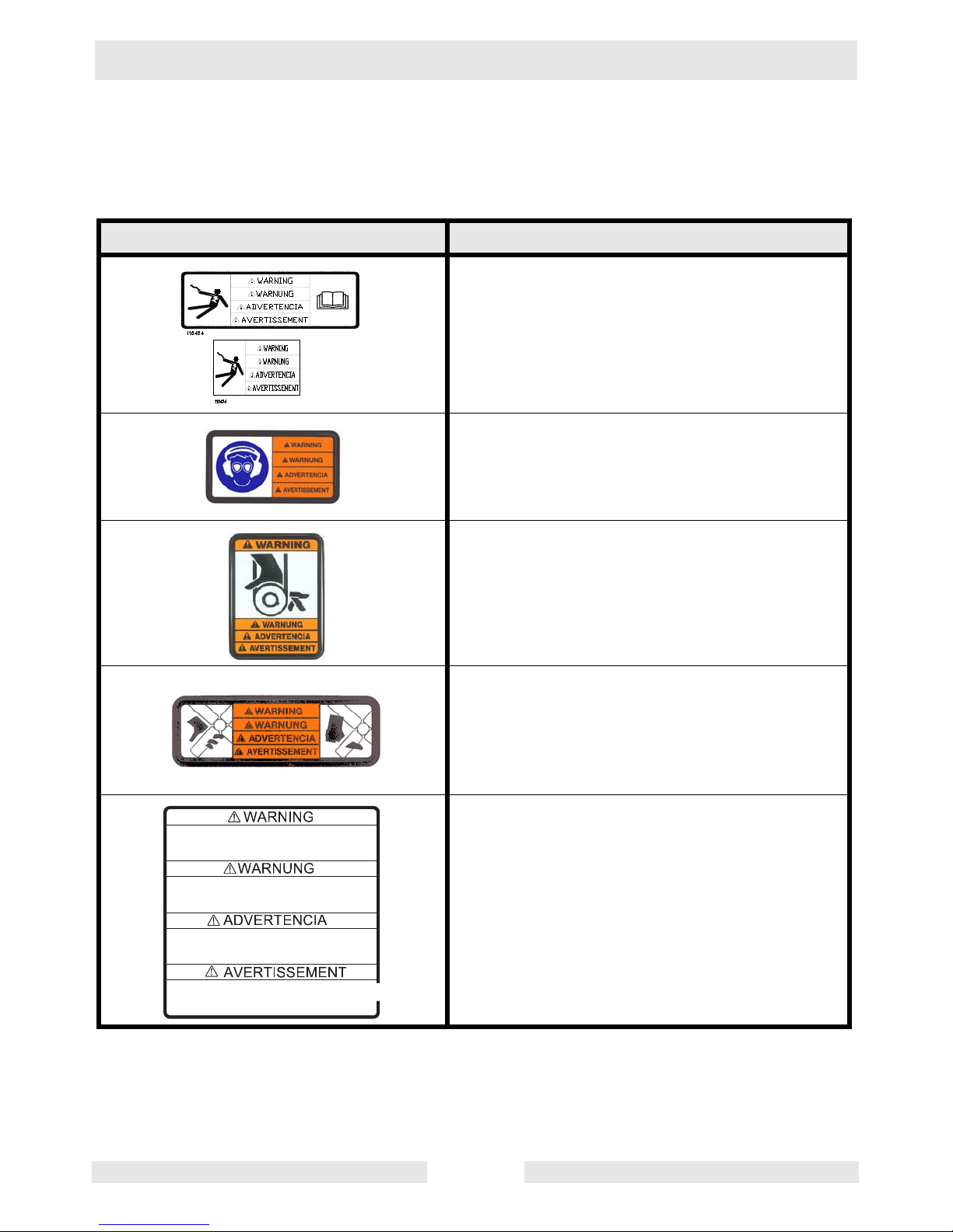
1.5 Safety and Information Labels
Wacker Neuson machines use international pictorial labels where
needed. These labels are described below:
Label Meaning
WARNING!
Electric shock hazard. Read Operator’s Manual for instructions.
WARNING!
Always wear hearing and eye protection when
operating this machine.
R e m o v e p a n f r o m t r o w e l b e f o r e l i f t i n g m a c h i n e
o v e r h e a d .
P a n s c a n f a l l a n d c a u s e d e a t h o r s e r i o u s i n j u r y i f
a p e r s o n i s h i t .
G l e i t s c h e i b e v o m B e t o n g l ä t t e r e n t f e r n e n b e v o r
d a s G e r ä t u b e r K o p f h ö h e g e h o b e n w i r d .
G l e i t s c h e i b e k a n n f a l l e n u n d s c h w e r e V e r l e t z u n g
o d e r T o d v e r u r s a c h e n w e n n P e r s o n a l g e t r o f f e n w i r d .
Q u i t e e l d i s c o d e f l o t a c i ó n a n t e s d e l e v a n t a r l a
m á q u i n a a l i s a d o r a d e h o r m i g ó n .
L o s d i s c o s p o d r í a n c a e r y m a t a r o l a s t i m a r
s e r i a m e n t e a u n a p e r s o n a q u e s e e n c u e n t r e c e r c a .
A v a n t d e l e v e r l a p p a r e i l a u - d e s s u s d e v o t r e t ê t e ,
ô t e r l e d i s q u e d e t a l o c h a g e d e l a t r u e l l e .
L e d i s q u e d e t a l o c h a g e p e u t t o m b e r e t e n t r a î n e r
d e g r a v e s b l e s s u r e s o u m ê m e l a m o r t .
WARNING!
Hand injury if caught in moving belt.
Always replace beltguard.
WARNING!
Cutting hazard. Always replace blade guard!
WARNING!
Remove pan from trowel before lifting machine
overhead. Pans can fall and cause death or
serious injury if a person is hit. (Located on top
side of float pan.)
1 1 8 6 8 8
12
Page 13

CT 36-400E Safety Information
Label Meaning
o
l
l
2
2
l
o
o
l
o
l
l
2
2
Turn motor switch to “ON” position.
o
l
l
2
2
Engage operator present lever.
l
o
Release operator present lever.
O
l
Turn motor switch to "OFF" position.
o
l
l
2
2
CAUTION!
Read and understand the supplied Operator’s
Manual before operating this machine. Failure
to do so increases the risk of injury to yourself
or others.
CAUTION!
Lifting point.
13
Page 14
Safety Information CT 36-400E
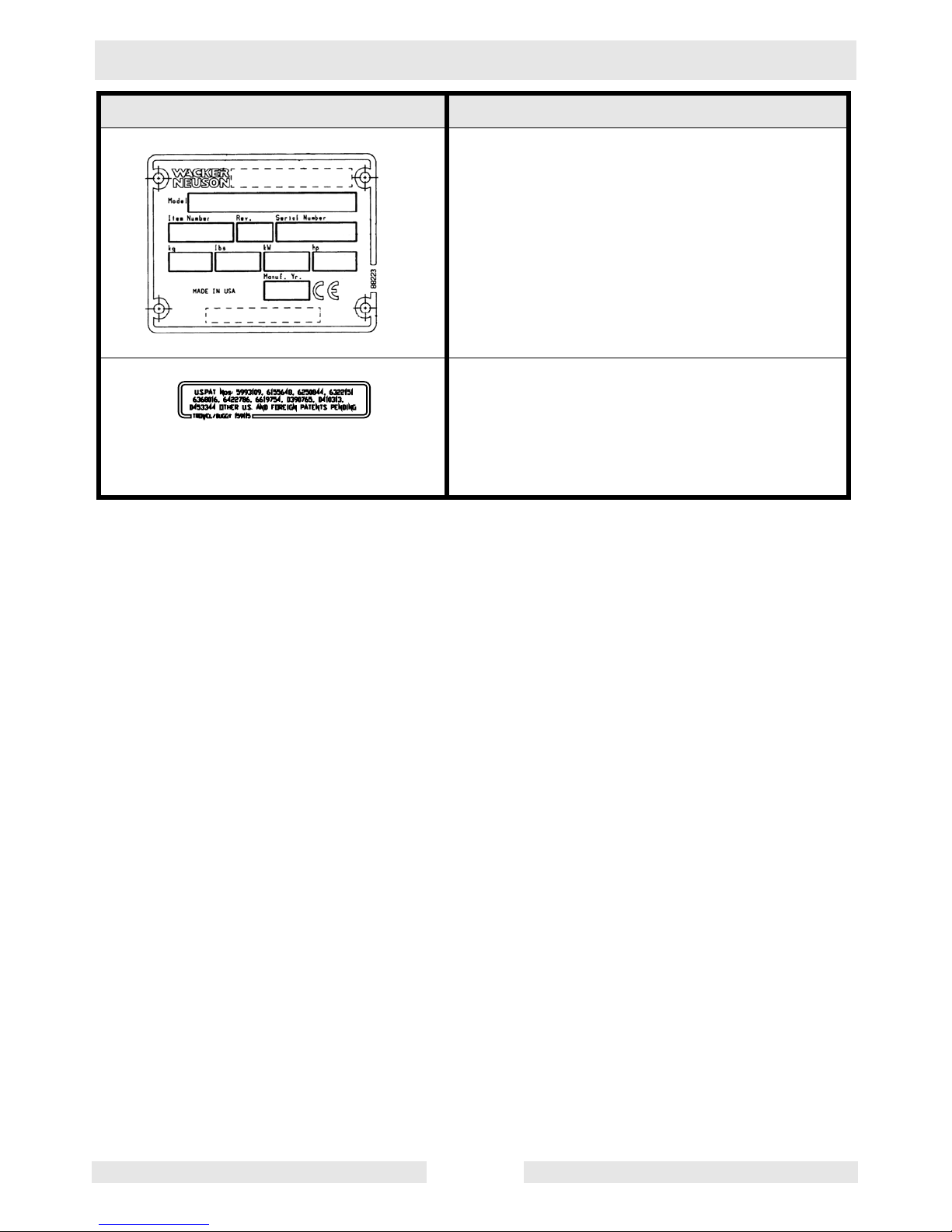
Label Meaning
A nameplate listing the model number, item
number, revision number, and serial number is
attached to each unit. Please record the information found on this plate so it will be available should the nameplate become lost or
damaged. When ordering parts or requesting
service information, you will always be asked
to specify the model number, item number,
revision number, and serial number of the unit.
This machine may be covered by one or more
patents.
14
Page 15

CT 36-400E Operation
2. Operation
2.1 Application
This trowel is a modern, high production machine intended for floating
and finishing freshly poured concrete slabs. The machine’s good
balance, adjustable handle, and easily reached controls add to
operator comfort and productivity. An Operator Present Lever provides
added operator safety. Finishing rates will depend on operator skill and
job conditions.
DO NOT use this machine for any application other than troweling
concrete.
15
Page 16

Operation CT 36-400E
2.2 Installing Blades
See Graphic: wc_gr001097
There are four types of blades available for the trowels. Float pans are
large "pizza pan" style blades, which hook on over finish or
combination blades and are available for the 36" machines only. Float
blades are available for all machines and clip on over finish or
combination blades. Both are used in the earliest stages of work, and
are not pitched.
Finish blades are used in the final stages of working, and are
progressively pitched to burnish the concrete.
Combination blades can be used throughout the concrete working
process. They are used in place of float blades or pans and finish
blades.
Note: Trowel blades must NOT be interchanged, i.e., do NOT put
larger diameter blades on a smaller diameter trowel.
2.2.1 Finish blades are flat on both edges and can be installed in either
direction.
When installing combination blades, orient blades as shown (a). This
positions the raised edges of the blade correctly for the clockwise
rotation of the machine.
2.2.2 Secure blades to trowel arms with screws (b). Dip threads of screws in
grease prior to installation. This will prevent concrete from cementing
the screws in place and will make removal of the blades easier later on.
2.2.3 Plug the remaining threaded holes in the blade brace with plastic plugs
(c) to prevent them from filling with concrete.
Do not lift the trowel overhead with a float pan attached, as the pan
could fall off and strike personnel working in the vicinity.
WARNING
b
c
a
wc_gr001097
16
Page 17

CT 36-400E Operation
2.3 Adjusting Handle
See Graphic: wc_gr002634
2.3.1 Straighten the foldable handle and tighten the knob (d) to secure the
handle in position.
2.3.2 Position the adjustable handle by loosening the knob (c) and adjusting
the handle up or down to suit the operator. Tighten the knob to secure
the handle in position.
2.3.3 Test the function of the operator present lever (a), by starting the trowel
and disengaging the lever. The trowel should stop promptly. See To
Start.
17
Page 18

Operation CT 36-400E
2.4 Installing Plugs and Power Cords
See Graphic: wc_gr0001177
The trowel comes with a 5-prong plug for connecting to 400V, 3Ø
power.
To reduce the risk of electric shock, only a certified electrician should
install or service power plugs, cords, or electrical boxes.
WARNING
2.5 Connecting to Power Supply
To reduce the risk of electric shock, all equipment must be properly
grounded. Connect this trowel to grounded receptacles and extension
DANGER
2.5.1 Check that the motor On/Off switch on the trowel is in the “0” (stop)
2.5.2 Make sure the power supply matches the voltage requirements listed
2.5.3 This machine must be grounded while in use to protect the operator
cords only. Make sure power supply has either an Earth Leakage
Circuit Breaker (ELCB) or an isolation monitor in the circuit.
position before connecting to a power source.
on motor label. Running the trowel at a low voltage will cause it to run
slow. This will reduce performance and cause the motor to overheat.
from electric shock.
18
Page 19

CT 36-400E Operation
2.6 Extension Cords
When choosing an extension cord, make sure it has adequate wire
size for safety. An undersized cord will cause a drop in line voltage
resulting in a loss of power and overheating. The table below shows
the correct wire size to use depending on cord length. If in doubt, use
the next heavier cord size. On motors being used outdoors, use
extension cords rated for outdoor use.
Improper use of extension cords can cause overheating and create
serious fire or shock hazards. NEVER use worn or damaged cords!
WARNING
Extension cord length
(meters)
0–20 1.0
20–40 1.5
40–80 1.5
80–100 2.5
Minimum extension cord size (mm
400 V / 3Ø / 7.3 Amp
2
)
19
Page 20

Operation CT 36-400E
2.7 Controls
See Graphic: wc_gr002634
Ref. Description Ref. Description
a Operator present lever d Foldable handle adjustment
b Twist pitch control e Power cord
c Handle height adjustment
2.8 Before Starting
Before starting the trowel, check the following:
• condition of the electrical cord
• motor box, switch box, and terminal box covers are tight
• oil level in gearbox
• condition of trowel arms and blades
• label locations and descriptions
• condition of ring guard
• adjustable lever is tight
20
Page 21

CT 36-400E Operation
2.9 To Start
See Graphic: wc_gr002634, wc_gr001174
2.9.1 Make sure the On/Off switch (f) is in the Off “0” position.
2.9.2 Plug the power cord (e) into a properly sized receptacle.
DO NOT operate the trowel with the Operator Present Lever (safety
interlock) disabled. Serious injury could occur if struck by rotating
WARNING
2.9.3 Turn the motor On/Off switch to the right to position “I” (f1) for low-
2.9.4 Engage the Operator Present Lever (a).
2.9.5 Note: The operator present lever must be fully engaged to run the
trowel due to disabling this interlock.
speed operation (approx. 50 RPM) or “2” (f2) for high-speed operation
(approx. 100 RPM).
trowel.
If the trowel does not run, it may be due to a mismatch between the
phase rotation of the motor and that of the power supply. Attempt to
start the trowel by turning the switch to “0” then to the left to “I” or “2”
and engaging the operator present lever. If the trowel still will not run,
contact Wacker Corporation or a certified electrician.
f0
f1
e
f2
f
wc_gr001174
21
Page 22

Operation CT 36-400E
2.10 To Stop
See Graphic: wc_gr002634, wc_gr001174
2.10.1 Release operator present lever (b).
2.10.2 Place ON/OFF Switch to the “0” (OFF) position.
2.11 Optional Weights
To install optional weights, place equal number of weights in both front
and rear of guard ring in designated area. Tighten screw to keep
weights in place.
Under no circumstances should any object be used as additional
weight other than the weights recommended by Wacker Neuson. The
WARNING
use of unauthorized weights could lead to personal injury or machine
damage.
22
Page 23

CT 36-400E Operation
2.12 Pitch Adjustment
See Graphic: wc_gr002613
To adjust blade pitch (angle):
A = Twist pitch: turn the pitch adjusting knob (a) clockwise to increase
pitch and counterclockwise to decrease pitch.
Ref. B = Working condition of concrete C = Suggested working pitch
1 Wet surface working stage Flat (no pitch)
2 Wet to plastic working stage Slight pitch (5°)
3 Plastic working stage Additional pitch (10°)
4 Semi-hard working stage to
hard finishing stage (burnishing)
For final finishing stages, it is sometimes desirable to add weights to the trowel guard rings to
increase the burnishing force. Wacker supplies weight kits for this purpose.
A
B
Maximum pitch (15°-30°)
C
1
a
2
5˚
3
10˚
4
15-30˚
wc_gr002613
23
Page 24

Operation CT 36-400E
2.13 Operation
See Graphic: wc_gr003239
Choose correct blade type and attach blades to trowel arms. Do not
mix float or finish blades with combination blades.
Note: When operating on soft concrete, do not let trowel stand in one
spot too long. Always lift trowel from slab when operation is complete.
Note: “Left” and “Right” references are made from the operator's
position.
2.13.1 Adjust handle height to suit operator. See Installing and Adjusting
Handles.
2.13.2 Start the trowel per To Start.
2.13.3 To move trowel forward twist handle clockwise (a).
2.13.4 To move backward twist handle counterclockwise (b).
2.13.5 To move to the left lift up slightly on the handle (c).
2.13.6 To move to the right press down slightly on the handle (d).
2.13.7 Clean trowel after each use to remove concrete splatter.
Personnel other than the trowel operator should not be allowed in the
work area, as severe injury can occur from contact with operating
WARNING
trowel blades.
It is recommended that each set of work passes be at 90° to the
previous set of work passes. This will help prevent the creation of
valleys in the slab surface.
For example, in the illustration, the second set of work passes (2) is
90° to the first set of work passes (1).
Be careful when changing directions that the electrical cord does not
become wrapped around the trowel or the trowel blades.
WARNING
24
Page 25

CT 36-400E Operation
a
1
c
d
2
b
wc_gr003239
25
Page 26

Maintenance CT 36-400E
3. Maintenance
3.1 Periodic Maintenance Schedule
Inspect all electrical cords before each use and have damaged cords
replaced or repaired at an authorized service center.
Check external hardware.
Grease cam followers.
Check drive belt.
Clean trowel after each use by flushing with water to remove concrete
splatters. DO NOT use a high pressure washer for the cleaning of
electrical equipment. The working tools must be thoroughly washed.
3.2 Trowel Lubrication
See Graphic: wc_gr001755
Grease trowel arms (b) with Shell Alvania RL2 grease or equivalent.
Oil the pitch control cable and other parts of trowel on an as needed
basis.
Oil in the gearbox should not require replacement unless it was
drained to service gearbox. Check quantity through plug (a) located on
side of gearbox. Oil level should be to bottom of the plug threads. See
Technical Data for oil quantity and type.
Daily
before
starting
After
first
20 hrs.
Every
50
hrs.
Every
100
hrs.
WACKER NEUSON
26
Page 27

CT 36-400E Maintenance
e
3.3 Belt Replacement
See Graphic: wc_gr003538
On new machines or after installing a new belt, check belt tension after
the first 20 hours of operation. Check and adjust belt every 100 hours
thereafter.
To change the belt:
3.3.1 Make sure that the trowel is unplugged from any electrical supply.
3.3.2 Loosen the screws (d) and remove the belt guard (c).
3.3.3 Loosen the motor plate jam nuts (e). Slide plate toward handle to
loosen belt.
3.3.4 Slowly turn pulley (b) and roll belt (a) off.
Note: The pulleys are aligned at the factory and neither should be
removed during belt replacement.
3.3.5 Install new belt on the pulleys. Adjust tension on belt by moving the
motor plate. Belt deflection should be 6–10 mm (1/4–3/8"), checked
half way between the pulleys. Tighten the jam nuts. Torque the screws
to 25 Nm (18 ft.lbs.).
3.3.6 Reattach the belt guard with washers and screws. Torque the screws
to 5 Nm (3.7 ft.lbs.).
a
b
c
d
6–10 mm
(1/4–3/8 in.)
wc_gr003538
27
Page 28
Maintenance CT 36-400E
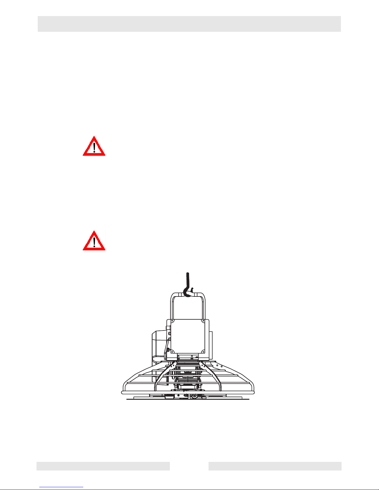
3.4 Lifting
See Graphic: wc_gr003554
To lift the machine manually:
3.4.1 Stop motor and unplug.
3.4.2 Obtain a partner and plan the lift.
3.4.3 Balance the weight between the partners and lift the machine by the
guard ring.
To reduce risk of back injury while lifting, keep your feet flat on ground
and shoulder width apart. Keep your head up and back straight.
WARNING
To lift the machine mechanically:
3.4.1 Stop motor and unplug.
3.4.2 See Dimensions and Weight for weight of machine and be sure that
lifting device(s) can safely lift the weight.
3.4.3 Attach hook, harness, or cable to the lifting bracket on machine as
shown and lift as desired.
Do not lift the trowel overhead with a float pan attached, as the pan
could fall off and strike personnel working in the vicinity.
WARNING
wc_gr003554
28
Page 29

CT 36-400E Maintenance
3.5 Storage
If trowel is being stored for more than 30 days:
Cover trowel and motor and store in a clean, dry area.
3.6 Troubleshooting
Problem / Symptom Reason / Remedy
Trowel does not develop full
speed.
Motor runs; poor trowel opera-
tion.
Motor does not run, or runs
erratically.
Motor stops, won't restart. • Motor overload switch has tripped. Contact Wacker
• Power supply is not proper voltage.
• Clean debris from moving parts and trowel blades.
• Check belt for wear or damage. Tighten belt if necessary.
• Clean debris from moving parts and trowel arms.
• Check motor on/off switch position.
• Phase rotation of motor may be mismatched with the
power supply. Turn on/off switch to opposite side.
• Check fuse in control box. Replace if necessary.
Corporation or a certified electrician.
• Check fuse in control box. Replace if necessary.
29
Page 30

Maintenance CT 36-400E
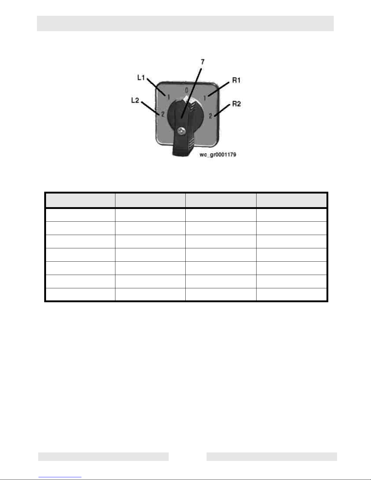
3.7 Electrical Schematic
See Graphic: wc_gr001178, wc_gr001179
Ref. Description Ref. Description
A Motor B Control box
1. Phase-sensing module 6. Contacts from selector switch
2. Transformer 7. Selector switch
3. Operator Present lever 8. Motor overload switch
(located in motor)
4. Contactor A 9. Fuse
5. Contactor B
5L3-B
1L1-A
3L2-A
L2 L3
6
12
5
9
13
13
3L2
1L1
2T1
4T2
15
3
4
L1
L3
24V
L1
11
L2
L2
8
1L1
14
24
2T1
L3
11 9
3L2 5L3
5
4T2
6T3
9
A1
A2
7
18
20
22
24
11
15
5L3-A
1L1-B
3
0
8
12
16
1
2
400V
I
6
3L2-B
10
14
17
19
21
23
18
5L3
4
A1
A2
6T3
A B
W1
U2
V1
U1
W2
V2
L1
wc_gr001178
30
Page 31
CT 36-400E Maintenance
L1 contacts closed L2 contacts closed R1 contacts closed R2 contacts closed
3-4 3-4 1-2 1-2
5-6 5-6 7-8 7-8
13-14 9-10 13-14 9-10
15-16 11-12 15-16 11-12
21-22 17-18 21-22 17-18
- 19-20 - 19-20
- 23-24 - 23-24
31
Page 32

Maintenance CT 36-400E
Notes
32
Page 33

CT 36-400E Technical Data
4. Technical Data
4.1 Dimensions and Weight
Dimensions mm (in.) Weight kg (lbs.)
A 1537 (60-1/2) without float pan 68 (151)
B 610 (24) with float pan 74 (163)
C 972 (38-1/4)
D 940 (37)
E 839 (33)
33
Page 34

Technical Data CT 36-400E
4.2 Motor
Item No.
CT 24-230E
0620377
Motor
Make Volt Elektrik
Model VM90L-2
Motor output
Motor speed
Power requirements
Frequency
Operating current
kW (HP)
rpm
Volts/phase
Hz
Amps
2.2 (3.0)
2870
220 / 1Ø
50
5.5 / 7.3
IP rating 55 / 1Ø
4.3 Trowel
Item No.
CT 36-400E
0009448
Trowel
Trowel Diameter*
mm (in.)
915 (36)
Number of Blades 4
Gear Box Lubrication
Speed Range
Pitch Range
*Trowel blades must NOT be interchanged, i.e., do NOT put larger diameter blades on a
smaller diameter trowel.
type/
ml (oz.)
rpm
degrees
Mobil Glygoyle 460
Approx. 620 (21)
50 / 100
0 – 30°
34
Page 35

CT 36-400E Technical Data
4.4 Sound and Vibration Data
The required sound specification, Paragraph 1.7.4.f of 89/392/EEC
Machinery Directive, is:
• the sound pressure level at operator’s location (L
• the guaranteed sound power level (L
) = 98 dB(A)
WA
) = 85 dB(A)
pA
These sound values were determined according to ISO 3744 for the
sound power level (LWA) and ISO 6081 for the sound pressure level
(LpA) with the unit running at high speed.
• The weighted effective acceleration value, determined according to
ISO 8662 Part 1, is = 1.6 m/s
2
The sound and vibration specifications were obtained with the unit
operating on wetted and cured concrete at full engine speed.
35
Page 36

Page 37

Page 38

SAFETY ALERT SYMBOL
This Safety Alert Symbol means
ATTENTION is required!
The Safety Alert Symbol identifies important safety
messages on machines, safety signs, in manuals
or elsewhere. When you see this symbol, be alert
to the possibility of personal injury or death. Follow
the instructions in the safety message.
Why is SAFETY important to YOU?
3 BIG REASONS
• Accidents KILL or DISABLE
• Accidents COST
• Accidents CAN BE AVOIDED
1
NOTICE OF COPYRIGHT PROTECTION
AEM Safety Manuals are protected as a copyrighted work with
ownership duly registered with the Copyright Office,
Washington, D.C. Any reproduction, translation, decompiling or
other use of an AEM Safety Manual, or portion thereof, or the
creation of derivative works based on an AEM Safety Manual,
without the prior written approval of AEM is expressly prohibited.
Copyright infringement can result in civil and criminal sanctions,
damages and other penalties being imposed.
Copyright © 2003 – Association of Equipment Manufacturers
!
Trowel.qxd 11/24/04 10:18 AM Page 1
U.S. Department of Labor publishes Safety and
Health Regulations and Standards under the
authority of the Occupational Safety and Health Act
for the General Construction and Mining Industries.
Its address is: U.S. Department of Labor,
Washington, DC 20210 (www.OSHA.gov and
www.MSHA.gov).
ANSI – American National Standards Institute, c/o
The American Society of Mechanical Engineers,
United Engineering Center, 345 East 47th Street,
New York, NY 10017 (www.ANSI.org).
ISO – International Standards Organization,
1, rue de Varembe Case postale 56, CH-1211
Geneva 20, Switzerland (www.ISO.ch).
SAE – Society of Automotive Engineers, Inc.,
400 Commonwealth Drive, Warrendale, PA 15096,
publishes a list, “Operator Precautions” SAE J153
MAY 87 (www.SAE.org).
AEM – Association of Equipment Manufacturers,
111 East Wisconsin Avenue, Milwaukee, WI 53202
(www.AEM.org).
WORD OF EXPLANATION
2
The following is a partial list of reference material on safe operating practices:
Trowel.qxd 11/24/04 10:18 AM Page 2
Page 39

3
TABLE OF CONTENTS
Page
WORD OF EXPLANATION ................................................................2
FOREWORD........................................................................................4
A WORD TO THE USER ....................................................................5
FOLLOW A SAFETY PROGRAM ......................................................6
PREPARE FOR SAFE OPERATION ..................................................7
START SAFELY ................................................................................11
WORK SAFELY ................................................................................13
SHUT DOWN SAFELY......................................................................15
LOAD AND UNLOAD SAFELY ........................................................16
PERFORM MAINTENANCE SAFELY ..............................................17
TEST YOUR KNOWLEDGE..............................................................22
A FINAL WORD TO THE USER........................................................23
Trowel.qxd 11/24/04 10:18 AM Page 3
This safety manual is intended to point out some of
the basic situations which may be encountered
during the normal operation and maintenance of
your walk-behind or ride-on concrete power trowel
and to suggest possible ways of dealing with these
conditions.
Additional precautions may be necessary,
depending on application and attachments used
and conditions at the work site or in the
maintenance area.
The trowel manufacturer has no direct control over
machine application, operation, inspection,
lubrication, or maintenance. Therefore, it is your
responsibility to use good safety practices in these
areas.
Do not use the trowel for any purpose other than its
intended purposes or applications.
The information provided in this manual
supplements the specific information about your
machine and its application that is contained in the
manufacturer’s manual(s).
Other information which may affect the safe
operation of your machine may be displayed on
safety signs, or in insurance requirements,
employer’s safety programs, safety codes, local,
state/provincial, and federal laws, rules, and
regulations.
If you do not understand any of this information, or
if errors or contradictions seem to exist, consult
with your supervisor before operating your trowel!
IMPORTANT: If you do not have the
manufacturer’s manual(s) for your particular
machine, get a replacement manual from your
employer, equipment dealer, or manufacturer of
your machine. Keep this safety manual and the
manufacturer’s manual(s) accessible to the
operator and maintenance personnel.
FOREWORD
4
Trowel.qxd 11/24/04 10:18 AM Page 4
Page 40

Remember that YOU are the key to safety. Good
safety practices not only protect you but also
protect the people around you. It is your
responsibility to study this manual and the
manufacturer’s manual(s) for your specific machine
before operating your machine. Make them a
working part of your safety program. Keep in mind
that this safety manual is written for concrete power
trowels only. Practice all other usual and customary
safe working precautions, and above all –
REMEMBER – SAFETY IS UP TO YOU
YOU CAN PREVENT SERIOUS
INJURY OR DEATH
A WORD TO THE USER
5
Trowel.qxd 11/24/04 10:18 AM Page 5
EQUIPMENT/CLOTHING
Consult your supervisor for specific instructions on
a job, and the personal safety equipment required.
For instance, you may need:
• Hard Hat
• Heavy Gloves
• Eye Protection
• Ear Protectors
• Safety Shoes
• Dust Mask or Respirator
Do not wear loose clothing or any accessory –
flopping cuffs, dangling neckties and scarves, or
jewelry – that can catch in moving parts.
DUST PRECAUTION
Some dust created by construction activities may
cause silicosis or respiratory harm.
Your risk of exposure varies depending on how
often you do this type of work. To reduce your risk,
work in a well ventilated area, use a dust control
system, and wear approved personal safety
equipment such as a dust/particle respirator
designed to filter out microscopic particles.
FOLLOW A SAFETY PROGRAM
6
Trowel.qxd 11/24/04 10:18 AM Page 6
Page 41
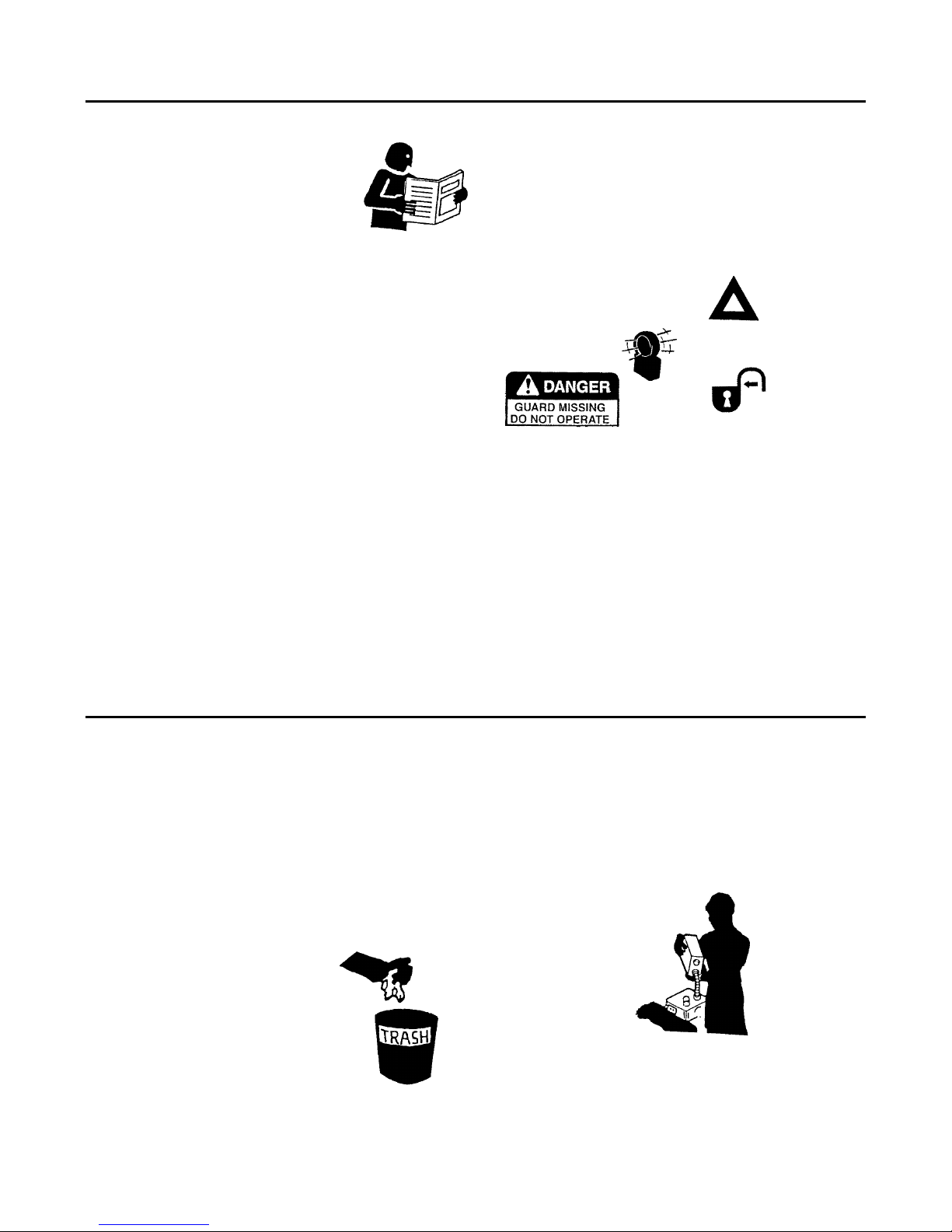
LEARN TO BE SAFE
• Read the operator’s
manual. If one has not
been provided, get one and
study it before operating
the equipment.
• Learn the location and
understand the functions of
all controls before
attempting to operate the
equipment.
• Know the meaning of all identification symbols on
the controls and gauges.
• Check to determine that the manufacturer’s
furnished safety warning labels are securely
attached to the trowel and all warnings can
clearly read. Replace labels and decals if they
are missing or become worn or unreadable.
• Know the location and type of emergency shutdown control the trowel is equipped with.
• Never start or operate the trowel without
protective guards and panels in place.
• Know the capabilities and limitations of the
trowel.
SAFETY DEVICES
Know what safety devices your trowel is equipped
with … and see that each item is securely in place
and in operating condition.
For example:
• Emergency stop switch or other “Shut-Down”
devices
• Guards, Shields & Panels
• Alarms or Warning Lamps
• Drain Covers, Plugs, and Caps
• Pressure Relief Devices
• Lights
7
PREPARE FOR SAFE OPERATION
Trowel.qxd 11/24/04 10:18 AM Page 7
PRE-OPERATIONAL CHECKS
Walk around the trowel. Carefully inspect for
evidence of physical damage, such as cracks,
bends, or deformation of plates and welds. Check
for loose, broken or missing parts on the trowel,
including brackets, vibration isolators, nuts and
bolts. Hardware should be replaced with original
equipment manufacturer’s (OEM) parts, and should
be properly tightened to the manufacturer’s
recommendations.
Remove all trash and debris from the trowel. Make
sure oily rags, leaves, or other flammable material
are removed and not stored on the trowel. Avoid
potential fire hazards!
Clean all oil or grease
from operator areas such
as control handles, foot
pedals, or platforms to
prevent slipping.
Check for fuel, oil, and
hydraulic fluid leaks. All
leaks must be corrected
before the trowel is
operated.
Inspect all hydraulic hoses for cracks or signs of
wear and replace if necessary. Secure all caps and
filler plugs for all systems.
Always use a a flashlight or shielded trouble light
when checking for leaks – never use an open
flame. Never check for hydraulic leaks with your
hand. Hydraulic systems are under high pressure
and leaks in these systems can penetrate the skin
which can result in serious injury or even death.
Always use a piece of cardboard or wood when
looking for hydraulic leaks.
Be sure the trowel is
properly lubricated. See
that the fuel, lubricating oil,
coolant and hydraulic
reservoirs are filled to the
proper levels with the
correct fluids according to
the manufacturer’s
instructions and
recommendations.
8
PREPARE FOR SAFE OPERATION
Trowel.qxd 11/24/04 10:18 AM Page 8
Page 42

FIRE PREVENTION
Always stop the engine and allow it to cool before
refueling.
Never refuel –
• When engine is running
• Near open flame or sparks
• While smoking
• In poorly ventilated areas
Never overfill fuel tanks or fluid reservoirs. In the
event of a fuel spill, do not attempt to start the
engine until the fuel residue has been completely
wiped up, and the area surrounding the engine is
dry. Replace fuel cap securely after refueling.
Inspect electrical wiring for damage or wear.
Batteries produce explosive gas. Keep open flame
or sparks away.
In case of accident or fire, be ready to act quickly,
yet calmly. Do not panic. Knowing ahead of time
where to locate a first aid kit, fire extinguisher, or to
get assistance will help should an emergency
situation come up.
CHECK THE WORK AREA
Learn – beforehand –
as much about your
working area as
possible.
Be observant of other
workers, bystanders
and other machinery
in the area. Keep all
unauthorized,
untrained people and
children out of the
area while the trowel
is in operation.
9
PREPARE FOR SAFE OPERATION
Trowel.qxd 11/24/04 10:18 AM Page 9
CHECK THE AREA
Thoroughly check the area for unusual or
dangerous conditions, such as tools, or items that
may damage the trowel or be propelled by the
trowels rotating blades. Note where pipes and
forms are located. Locate and mark protrusions
(rebar, anchor bolts, floor drains, etc.) in the
concrete.
GETTING ON AND OFF A RIDE-ON TROWEL
If operating a ride-on trowel, mount and dismount
carefully. Use the steps and hand holds provided.
Do not use control levers as hand holds and never
use guard rings as steps. Watch for surfaces that
may be slippery. Never jump off a ride-on trowel.
OPERATING ON AN ELEVATED DECK
(MULTI-STORY OPERATION)
Consult local/state regulations before you operate
equipment on an elevated deck. If operating on an
elevated deck, ensure perimeter safety cabling of
proper size and strength is in place. Do not operate
the trowel close to the edge of the deck.
TRANSPORTING THE TROWEL
Never transport the trowel with float pans attached
unless safety catches are used and are specifically
cleared for such transport by the manufacturer.
Under no circumstances hoist the trowel more than
three feet off the ground with float pans attached.
Always consult the manufacturer’s operation
manual for specific information on transporting the
trowel.
10
PREPARE FOR SAFE OPERATION
Trowel.qxd 11/24/04 10:18 AM Page 10
Page 43

START CORRECTLY – START SAFELY
Before starting, check for proper functioning of all
operation and shutdown controls. Check all
controls to be sure they are in the correct startup
position. Know the proper starting procedure for
your trowel. Follow the manufacturer’s operational
instructions.
WALK-BEHIND TROWELS
• Ensure that the operator is familiar with the
trowel and is trained on its operation.
• Ensure the operator is well rested, not fatigued,
is alert, and not impaired in any way
(medications, drugs, alcohol, etc.).
• Do not start or operate the trowel if the drive train
will not disengage. Centrifugal force between the
trowel and surface when starting can cause
uncontrolled handle movement that can cause
serious injury. The handle must not move while
pulling the engine recoil starter.
• Visually check to be sure that the blades are free
of obstructions and the area is clear for
operation.
• For trowels that use this feature, ensure that the
emergency stop switch is in the ON position.
• Move the throttle to the idle position.
• Switch the engine ON/OFF switch to the ON
position.
• Never place your foot on the ring guard when
starting the engine or severe injury can occur if
your foot slips through the ring guard as the
blades start to spin.
• While firmly holding the handle with one hand,
start the engine following the guidelines in the
engine manufacturer’s instruction manual.
• Hold the handle bar firmly with both hands while
the trowel is “throttled-up”.
• If control of the trowel is lost, stay clear and do
not attempt to regain control until the trowel has
stopped moving. Depending on the engine
speed, the trowel handle can swing around
before it stops completely.
• You are ready to operate the trowel!
11
START SAFELY
Trowel.qxd 11/24/04 10:18 AM Page 11
RIDE-ON TROWELS
• Ensure that the operator is familiar with the
trowel and is trained on its operation.
• Ensure the operator is well rested and not
fatigued, is alert, and not impaired in any way
(medications, drugs, alcohol, etc.).
• Adjust the seating if necessary and get into a
comfortable position where all controls are
accessible.
• Visually check to be sure that the blades are free
of obstructions and the area is clear for
operation.
• Start the trowel following the instructions in the
engine manufacturer’s operation manual. For
diesel powered trowels, follow the instructions for
glow plug and cold start operation.
• Observe any gauges and warning lights to
ensure they are functioning and their readings
are within the manufacturer’s normal operating
range.
• Check operation of controls. Make certain they
operate properly.
• You are ready to operate the trowel!
12
START SAFELY
Trowel.qxd 11/24/04 10:18 AM Page 12
Page 44

SAFE WORKING PROCEDURES
DANGER – CARBON MONOXIDE
Exhaust from the engine contains
poisonous carbon monoxide gas
that is not easily detected as it is
colorless and odorless. Exposure
to carbon monoxide can cause
loss of consciousness and may
lead to death! Do not operate
your trowel indoors or in an enclosed area unless
adequate ventilation is provided. Ensure that
permissible carbon monoxide levels are monitored
and not exceeded.
OTHER PRECAUTIONS
• Never leave the trowel unattended while it is
running.
• Always keep clear of rotating or moving parts.
• Never use additional weights other than the
weights recommended by the manufacturer. The
use of unauthorized weights could lead to
personal injury or damage to the trowel.
• Never fill the fuel tank while the engine is
running. Turn the engine off and allow it to cool
before refueling.
• The muffler, exhaust pipes and
other engine parts will become
hot during operation and will
remain hot for a while after
shutdown. Do not touch until
allowed to sufficiently cool. Do
not allow debris, rags, paper, or
leaves to accumulate around
these areas.
• Do not keep tools, buckets, loose materials on
the trowel while it is running and never allow
anyone other than the operator on or near the
trowel while it is in operation.
• Do not use the trowel for any purpose other than
its intended purposes or applications.
13
WORK SAFELY
Trowel.qxd 11/24/04 10:18 AM Page 13
ELECTRICAL EQUIPMENT
Some walk-behind trowels are powered by electric
motors. Electric motors and components present
special hazards during operation. Read the
operator’s manual.
• Never operate a trowel with a damaged or worn
electrical cord. When using an extension cord, be
sure to use one heavy enough to carry the
current load. When trowel is used outdoors, use
only extension cords that are marked for outdoor
use.
• Use only appropriate
extension cords that have
grounding-type plugs and
receptacles that accept the
machine’s plug.
• Keep all electrical cords away from rotating
elements, heat, oil, and sharp edges to avoid
damaging them.
• Avoid body contact with grounded surfaces such
as pipes, metal railings, radiators and metal
ductwork.
• Always check the power supply before running
the trowel. Using the wrong voltage supply will
damage the motor.
• Always make sure the motor switch is OFF or in
the stop position before plugging the trowel into
the power supply.
• Do not operate an electric powered trowel in the
rain or snow. Keep the motor, switch, and
electrical cords dry.
• Never operate the trowel in areas exposed to
flammable or explosive liquids or gases. Sparks
could ignite fumes.
14
WORK SAFELY
Trowel.qxd 11/24/04 10:18 AM Page 14
Page 45

SHUT DOWN PROCEDURES
Never disable or disconnect the safety devices!
Always close fuel valves when the machine is not
being used.
Refer to the manufacturer’s manuals for specific
shut down procedures.
15
SHUT DOWN SAFELY
Trowel.qxd 11/24/04 10:18 AM Page 15
PRECAUTIONS
• Power trowels are heavy and awkward to move
around.
• Do not attempt to lift the ride-on trowel by the
guard rings.
• Use proper heavy lifting procedures.
• Keep all non-essential personnel clear of the
area.
• Never hoist the trowel over areas where people
are standing or working.
• Remove tools and loose items before lifting.
• Make sure the crossbars on the safety catches
are in good condition if so equipped.
• Always consult your operator’s manual for the
best and proper lifting, loading, and unloading
methods.
WALK-BEHIND TROWELS
Some walk-behind trowels can be lifted or moved
by two people utilizing lifting tubes or other special
attachments. Generally however, they must be
lifted using lifting bales (special lifting brackets), or
other specific lifting points provided by the
manufacturer, and cranes, hoists, or forklifts. Be
certain any lifting devices used have adequate
capacity.
RIDE-ON TROWELS
Ride-on trowels are very heavy. They require
heavy-duty lifting devices such as cranes or heavyduty hoists to lift them on and off the concrete slab.
Be certain any lifting devices used have adequate
capacity. Some ride-on trowels are equipped with
lifting bosses that are used with specialized
apparatus to assist in moving the trowels around.
Use extreme care when lifting or moving a ride-on
trowel.
STORAGE
Always store equipment properly when it is not
being used. Equipment should be stored in a clean,
dry location out of reach of children.
LOAD AND UNLOAD SAFELY
16
Trowel.qxd 11/24/04 10:18 AM Page 16
Page 46

SERVICE AND MAINTENANCE SAFETY
Poorly maintained equipment
can become a safety hazard! In
order for your trowel to operate
safely and properly over a long
period of time, periodic
maintenance and occasional
repairs are necessary.
Do not attempt to clean,
service, or perform adjustments
on the trowel while it is running.
GOOD
HOUSEKEEPING
Keep area clean
and dry if possible.
Oily and wet
surfaces are
slippery; greasy
rags are a fire
hazard; wet spots
are dangerous
around electrical
equipment.
GENERAL PROCEDURES
Do not perform any work on the trowel unless you
are authorized to do so.
Standard maintenance procedures should always
be observed. Read the manufacturer’s manual or
find assistance if you do not understand what you
are doing.
Maintenance can be dangerous unless performed
properly. Be certain that you have the necessary
skill and information, correct tools and equipment
to do the job correctly.
Attach a Do Not Operate tag or
similar warning tag to the
control panel (or handle on
walk-behind trowels), and
disconnect the battery
(disconnect the spark plug wire
on walk-behind trowels), before
performing maintenance on the
machine.
Disconnect the electric cord on
electrical machines.
PERFORM MAINTENANCE SAFELY
17
Trowel.qxd 11/24/04 10:18 AM Page 17
FORM GOOD DRESS HABITS
Loose clothing and jewelry can catch in moving
parts and cause serious injury.
Keep hands – and clothing – away from moving
parts.
GUARDS AND SAFETY DEVICES
After performing maintenance make certain all
guards and panels have been reinstalled and all
safety devices are functional.
BATTERY MAINTENANCE
Always wear eye and face
protection.
Batteries produce explosive gases.
Keep open flame or sparks away.
See the manufacturer’s instructions
when servicing the batteries, when
using jumper cables, or when using
a battery charger.
Use a flashlight to check battery
electrolyte level. Always check
with engine stopped.
Battery electrolyte is poisonous.
It is strong enough to burn your
skin, eat holes in clothing, and
can cause blindness if splashed
into eyes. Always wear eye and
face protection.
Flush any contacted area with water immediately.
PERFORM MAINTENANCE SAFELY
18
Trowel.qxd 11/24/04 10:18 AM Page 18
Page 47

FIRE PREVENTION
Avoid fire hazards.
Always stop the engine and allow it to cool before
you refuel the trowel. Do not refuel while smoking
or near open flame or sparks. Never overfill fuel
tanks or fluid reservoirs.
Remove all trash or debris. Make sure oily rags or
other flammable materials are not stored on or in
the trowel.
Check for fuel, oil, or hydraulic fluid leaks. Repair
the leaks and clean the machine before you
operate it.
Inspect electrical wiring or worn or frayed
insulation. Install new wiring if wires are damaged.
Do not weld or flame cut on pipes, tubes, or tanks
that contain flammable fluids or gases.
Ether and starting fluid is flammable. Do not smoke
when using. Always follow the instructions on the
can and in the manufacturer’s manual for your
trowel.
Always use a safe, nonflammable solvent when
you clean parts. Do not use flammable fluids or
fluids that give off harmful vapors.
Store all flammable fluids and materials away from
your work area.
Whenever the sparkplug is removed, do not test for
spark on gasoline powered engines if engine is
flooded or the smell of gasoline is present. A stray
spark could ignite fumes.
Know where fire extinguishers are kept – how they
operate – and for what type of fire they are
intended!
Check readiness of fire suppression systems and
fire detectors (is so equipped).
PERFORM MAINTENANCE SAFELY
19
Trowel.qxd 11/24/04 10:18 AM Page 19
EXHAUST FUMES
Engine exhaust fumes can
cause sickness or death.
When performing
maintenance, if it is
necessary to run an engine
in an enclosed area, remove
the exhaust fumes from the
area when an exhaust pipe extension. If you do not
have an exhaust pipe extension, make sure you
open the doors and get outside air into the area.
Ensure that permissible carbon monoxide levels
are monitored and not exceeded.
FLUID SIPHONING
Never siphon gasoline or hydraulic fluid using a
hose and suction by mouth. Ingestion of these
fluids even in small amounts will require immediate
medical attention and can cause death.
COOLING SYSTEM
Maintain the cooling system
according to the
manufacturer’s instructions.
Hot coolant can spray out
and you can be burned if you
improperly maintain or
service the cooling system.
Remove filler cap only when
cool.
PERFORM MAINTENANCE SAFELY
20
Trowel.qxd 11/24/04 10:18 AM Page 20
Page 48

TROWEL BLADES AND PANS
• Do not attempt to clean, service or perform
adjustments on the trowel while it is running.
• Do not remove while the trowel is hanging
overhead. Always support the trowel securely on
a flat, level surface before changing blades or
pans.
• Always handle blades and pans carefully. Worn
blades or pans may develop sharp edges that
can cause serious cuts.
• Always replace worn or damaged parts with
service parts designated by the manufacturer.
• Replace blades and pans as a complete set –
even if only one blade or pan is showing wear or
damage. They can wear differently depending on
different jobs, and a difference in blade size will
damage the finish of the slab surface.
HYDRAULIC SYSTEMS
Hydraulic fluid systems operate under high
pressure. Even a small leak can have enough force
to penetrate the eyes or skin. If injury occurs, seek
immediate medical treatment by a physician
familiar with injuries that are caused by hydraulic oil
escaping under pressure.
Use a piece of wood or cardboard to find hydraulic
oil leaks. Do not use your bare hands.
Wear safety glasses to prevent injuries to the eyes.
PERFORM MAINTENANCE SAFELY
21
Trowel.qxd 11/24/04 10:18 AM Page 21
Do you understand this AEM manual and items
such as –
• Your safety program?
• Your trowel manufacturer’s manual(s)?
• Proper clothing and personal safety equipment?
• Your trowel’s controls, warning signs and
devices, and safety equipment?
• Proper trowel lifting and moving procedures?
• How to inspect and start your trowel?
• How to check your trowel for proper operation?
• Proper working procedures?
• Proper shut down procedures?
• Your work area and any special hazards that
may exist?
• Under what conditions you should not operate
your trowel?
If you do not understand any of these items,
consult with your supervisor before operating your
trowel.
TEST YOUR KNOWLEDGE
22
Trowel.qxd 11/24/04 10:18 AM Page 22
Page 49

Remember that YOU are the key to safety. Good
safety practices not only protect you but protect the
people around you.
You have read this safety manual and the
manufacturer’s manual(s) for your specific trowel.
Make them a working part of your safety program.
Keep in mind that this safety manual is written for
only this type of machine.
Practice all other usual and customary safe
working precautions, and above all –
REMEMBER – SAFETY IS UP TO YOU
YOU CAN PREVENT SERIOUS
INJURY OR DEATH
A FINAL WORD TO THE USER
23
Trowel.qxd 11/24/04 10:18 AM Page 23
Trowel.qxd 11/24/04 10:18 AM Page 24
Page 50

AEM_ConcretePowerTrowel.qxd 7/23/03 6:31 AM Page 1
Page 51

EC DECLARATION OF CONFORMITY
CE-KONFORMITÄTSERKLÄRUNG
DECLARACIÓN DE CONFORMIDAD DE LA CE
DÉCLARATION DE CONFORMITÉ C.E.
WACKER NEUSON CORPORATION, N92 W15000 ANTHONY AVENUE, MENOMONEE FALLS, WISCONSIN USA
AUTHORIZED REPRESENTATIVE IN THE EUROPEAN UNION
BEVOLLMÄCHTIGTER VERTRETER FÜR DIE EUROPÄISCHE GEMEINSCHAFT
REPRESENTANTE AUTORIZADO EN LA UNIÓN EUROPEA
REPRÉSENTANT AGRÉÉ AUPRÈS DE L’UNION EUROPÉENNE
hereby certifies that the construction equipment specified hereunder / bescheinigt, daß das Baugerät / certifica que la máquina de
construcción / atteste que le matériel :
1. Category / Art / Categoría / Catégorie
WACKER CONSTRUCTION EQUIPMENT AG
Preußenstraße 41
80809 München
Trowel
Betonglätter
Alisadora de hormigón
Truelle mécanique
2. Type - Typ - Tipo - Type
CT 36, CT 48
3. Item number of equipment / Artikelnummer / Número de referencia de la máquina / Numéro de référence du matériel :
0009438, 0009439, 0009442, 0009443, 0009444, 0009447, 0009448, 0620106, 0009449, 0009450,
0009452, 0009453
has been produced in accordance with the following standards:
in Übereinstimmung mit folgenden Richtlinien hergestellt worden ist:
ha sido fabricado en conformidad con las siguientes normas:
a été produit conforme aux dispositions des directives européennes ci-après :
2002/88/EC
98/37/EC
89/336/EC
pr EN 12649
21.07.08
Date / Datum / Fecha / Date
2008-CE-CT36_48-Q.fm
William Lahner Robert Motl
Vice President of Engineering Manager, Product Engineering
WACKER NEUSON CORPORATION
Page 52

Wacker Construction Equipment AG · Preußenstraße 41 · D-80809 München · Tel.: +49-(0)89-3 54 02 - 0 · Fax: +49 - (0)89-3 54 02-3 90
Neuson Corporation · P.O. Box 9007 · Menomonee Falls, WI 53052-9007 · Tel. : (262) 255-0500 · Fax: (262) 255-0550 · Tel. : (800) 770-0957
Wacker
Wacker Asia Pacific Operations · Skyline Tower, Suite 2303, 23/F · 39 Wang Kwong Road, Kowloon Bay, Hong Kong · Tel. +852 2406 60 32 · Fax: +852 2406 60 21
 Loading...