

Wacker Neuson CT 36, CT 48 Repair Manual

www.wackergroup.com
0163091en 003
1007
Walk-Behind
Trowels
CT 36
CT 48
REPAIR MANUAL
0163091EN


CT Repair Foreword
This manual covers machines with Item Number:
0009438, 0009439, 0009442, 0009443, 0009444, 0009447, 0009449,
0009450, 0009452, 0009453, 0620106
Operating / Parts Information
You must be familiar with the operation of this machine before you
attempt to troubleshoot or make any repairs to it. Basic operating and
maintenance procedures are described in the operator’s / parts
manual supplied with the machine. The operator’s / parts manual
should be kept with the machine. Use it to order replacement parts
when needed. If this manual becomes lost, please contact Wacker
Corporation to order a replacement.
Damage caused by misuse or neglect of the unit should be brought to
the attention of the operator, to prevent similar occurrences from
happening in the future.
WARNING
This manual provides information and procedures to safely repair and
maintain the above Wacker model(s). For your own safety and
protection from injury, carefully read, understand, and observe all
instructions described in this manual. THE INFORMATION
CONTAINED IN THIS MANUAL IS BASED ON MACHINES
MANUFACTURED UP TO THE TIME OF PUBLICATION. WACKER
CORPORATION RESERVES THE RIGHT TO CHANGE ANY
PORTION OF THIS INFORMATION WITHOUT NOTICE.
CALIFORNIA
Proposition 65 Warning:
Engine exhaust, some of its constituents, and certain vehicle
components, contain or emit chemicals known to the State of
California to cause cancer and birth defects or other reproductive
harm.
wc_tx000550gb.fm 3

CT Repair Foreword
This manual provides information and procedures to safely operate
and maintain this Wacker model. For your own safety and protection
from injury, carefully read, understand and observe the safety
instructions described in this manual.
Keep this manual or a copy of it with the machine. If you lose this
manual or need an additional copy, please contact Wacker
Corporation. This machine is built with user safety in mind; however,
it can present hazards if improperly operated and serviced. Follow
operating instructions carefully! If you have questions about operating
or servicing this equipment, please contact Wacker Corporation.
The information contained in this manual was based on machines in
production at the time of publication. Wacker Corporation reserves the
right to change any portion of this information without notice.
All rights, especially copying and distribution rights, are reserved.
Copyright 2007 by Wacker Corporation.
No part of this publication may be reproduced in any form or by any
means, electronic or mechanical, including photocopying, without
express written permission from Wacker Corporation.
Any type of reproduction or distribution not authorized by Wacker
Corporation represents an infringement of valid copyrights and will be
prosecuted. We expressly reserve the right to make technical
modifications, even without due notice, which aim at improving our
machines or their safety standards.
wc_tx000550gb.fm 4

CT Repair Table of Contents
1. Safety Information 8
1.1 Laws Pertaining to Spark Arrestors ...................................................... 8
1.2 Operating Safety .................................................................................. 9
1.3 Operator Safety while using Internal Combustion Engines ................ 10
1.4 Service Safety .................................................................................... 11
1.5 Label Locations .................................................................................. 12
1.6 Safety and Information Labels ............................................................ 13
2. Technical Data 18
2.1 Dimensions and Weight ..................................................................... 18
2.2 Engine ................................................................................................ 20
2.3 Trowel ................................................................................................. 24
2.4 Sound and Vibration Data .................................................................. 25
3. Operation 26
3.1 Application .......................................................................................... 26
3.2 New Machine Set-up .......................................................................... 26
3.3 Recommended Fuel ........................................................................... 26
3.4 Installing Blades ................................................................................. 27
3.5 Installing and Adjusting Handles ........................................................ 28
3.6 Controls .............................................................................................. 30
3.7 Stop Button ......................................................................................... 31
3.8 Before Starting ................................................................................... 31
3.9 To Start - Honda ................................................................................. 32
3.10 To Stop - Honda ................................................................................. 33
3.11 To Start - Wacker ............................................................................... 34
3.12 To Stop - Wacker ............................................................................... 35
3.13 Engine Control Module ....................................................................... 36
3.14 Operation ............................................................................................ 36
3.15 Braking System .................................................................................. 38
3.16 Pitch Adjustment ................................................................................ 39
5

Table of Contents CT Repair
4. Maintenance 40
4.1 Periodic Maintenance Schedule - Honda ............................................40
4.2 Periodic Maintenance Schedule - Wacker ..........................................41
4.3 Engine Oil - Honda ..............................................................................42
4.4 Engine Oil - Wacker ............................................................................43
4.5 Air Cleaner - Honda .............................................................................44
4.6 Air Cleaner - Wacker ...........................................................................45
4.7 Spark Plug ...........................................................................................46
4.8 Cleaning Sediment Cup - Honda .........................................................47
4.9 Cleaning Fuel Strainer - Wacker .........................................................47
4.10 Adjusting Idle Speed - Honda ..............................................................48
4.11 Carburetor Adjustment - Honda ..........................................................49
4.12 Belt Replacement ................................................................................50
4.13 Trowel Lubrication ...............................................................................51
4.14 Optional Weights .................................................................................51
4.15 Lifting ...................................................................................................52
4.16 Storage ................................................................................................54
4.17 Troubleshooting ...................................................................................55
5. Guide Handle 56
5.1 Replacing the Throttle Cable ...............................................................56
5.2 Adjusting the Throttle Lever ................................................................58
5.3 Upper Handle/Twist Pitch Control—Exploded View ............................60
5.4 Upper Handle/Twist Pitch Control—Components ...............................61
5.5 Replacing the Upper Handle ...............................................................62
5.6 Replacing the Twist Pitch Control Cable .............................................64
5.7 Replacing the Lower Handle ...............................................................66
5.8 Replacing the Stop Switch ..................................................................67
6. Clutch 69
6.1 Replacing the Drive Belt ......................................................................69
6.2 Drive Belt—Standard Clutch ...............................................................70
6.3 Drive Belt—Variable Speed Clutch .....................................................71
6.4 Replacing the Standard Clutch ............................................................72
6.5 Standard Clutch—Exploded View .......................................................73
6.6 Standard Clutch Overhaul ...................................................................74
6.7 Replacing the Variable Speed Clutch ..................................................76
wc_br0163091en_003TOC.fm 6

CT Repair Table of Contents
7. Spider 78
7.1 Spider Assembly—Exploded View ..................................................... 78
7.2 Spider Assembly—Components ........................................................ 79
7.3 Replacing the Blades ......................................................................... 80
7.4 Replacing the Arms ............................................................................ 82
7.5 Balancing the Blade Pitch .................................................................. 84
7.6 Removing the Spider .......................................................................... 86
7.7 Installing the Spider ............................................................................ 88
7.8 Rebuilding the Lift Ring Assembly ...................................................... 90
8. Drivetrain 92
8.1 Drivetrain—Exploded View ................................................................. 92
8.2 Drivetrain—Components .................................................................... 93
8.3 Engine Removal ................................................................................. 94
8.4 Engine Installation .............................................................................. 96
8.5 Engine Wiring ..................................................................................... 98
8.6 Engine Wiring Components ................................................................ 99
8.7 Wiring Diagrams ............................................................................... 100
8.8 Engine Wiring Components .............................................................. 101
8.9 Replacing the Gearbox ..................................................................... 102
8.10 Gearbox—Exploded View ................................................................ 104
8.11 Gearbox—Components .................................................................... 105
8.12 Gearbox Disassembly ...................................................................... 106
8.13 Gearbox Assembly ........................................................................... 110
7

Safety Information CT 36 / CT 48
1. Safety Information
This manual contains DANGER, WARNING, CAUTION, NOTICE and
NOTE callouts which must be followed to reduce the possibility of
personal injury, damage to the equipment, or improper service.
This is the safety alert symbol. It is used to alert you to potential
personal injury hazards. Obey all safety messages that follow this
symbol to avoid possible injury or death.
DANGER indicates a hazardous situation which, if not avoided, will
result in death or serious injury.
DANGER
WARNING indicates a hazardous situation which, if not avoided, could
result in death or serious injury.
WARNING
CAUTION indicates a hazardous situation which, if not avoided, could
result in minor or moderate injury.
CAUTION
NOTICE: Used without the safety alert symbol, NOTICE indicates a
hazardous situation which, if not avoided, could result in property
damage.
Note: Contains additional information important to a procedure.
1.1 Laws Pertaining to Spark Arrestors
Notice: State Health Safety Codes and Public Resources Codes
specify that in certain locations spark arresters be used on internal
combustion engines that use hydrocarbon fuels. A spark arrester is a
device designed to prevent accidental discharge of sparks or flames
from the engine exhaust. Spark arresters are qualified and rated by
the United States Forest Service for this purpose.
In order to comply with local laws regarding spark arresters, consult
the engine distributor or the local Health and Safety Administrator.
wc_si000139gb.fm 8

CT 36 / CT 48 Safety Information
1.2 Operating Safety
Familiarity and proper training are required for the safe operation of
machine. Machines operated improperly or by untrained personnel
can be dangerous. Read the operating instructions contained in both
WARNING
1.2.1 NEVER allow anyone to operate this equipment without proper
1.2.2 NEVER touch the engine or muffler while the engine is on or
1.2.3 NEVER use accessories or attachments that are not recommended by
1.2.4 NEVER leave machine running unattended.
this manual and the engine manual and familiarize yourself with the
location and proper use of all controls. Inexperienced operators should
receive instruction from someone familiar with the machine before
being allowed to operate it.
training. People operating this equipment must be familiar with the
risks and hazards associated with it.
immediately after it has been turned off. These areas get hot and may
cause burns.
Wacker. Damage to equipment and injury to the user may result.
1.2.5 NEVER operate the machine with the beltguard missing. Exposed
drive belt and pulleys create potentially dangerous hazards that can
cause serious injuries.
1.2.6 NEVER operate this machine in applications for which it is not
intended.
1.2.7 NEVER use the trowel around pop-ups in the concrete that are lower
than the lowest ring on the ring guard.
1.2.8 NEVER lift the machine solely by the handle. The component may fail,
causing the machine to fall, possibly injuring bystanders.
1.2.9 ALWAYS wear protective clothing appropriate to the job site when
operating equipment.
1.2.10 ALWAYS wear hearing and eye protection when operating this
machine.
1.2.11 ALWAYS remain aware of moving parts and keep hands, feet, and
loose clothing away from the moving parts of the machine.
1.2.12 ALWAYS read, understand, and follow procedures in the Operator’s
Manual before attempting to operate the equipment.
1.2.13 ALWAYS store the equipment properly when it is not being used.
Equipment should be stored in a clean, dry location out of the reach of
children.
1.2.14 ALWAYS close fuel valve on engines equipped with one when
machine is not being operated.
wc_si000139gb.fm 9

Safety Information CT 36 / CT 48
1.2.15 ALWAYS operate machine with all safety devices and guards in place
and in working order. DO NOT modify or defeat safety devices. DO
NOT operate machine if any safety devices or guards are missing or
inoperative.
1.2.16 ALWAYS be sure operator is familiar with proper safety precautions
and operation techniques before using machine.
1.2.17 ALWAYS test the function of the engine control module before
operating the trowel. DO NOT operate the trowel if the engine control
module is not functioning properly.
1.3 Operator Safety while using Internal Combustion Engines
Internal combustion engines present special hazards during operation
and fueling. Read and follow the warning instructions in the engine
owner’s manual and the safety guidelines below. Failure to follow the
DANGER
1.3.1 DO NOT run the machine indoors or in an enclosed area such as a
warnings and safety guidelines could result in severe injury or death.
deep trench unless adequate ventilation, through such items as
exhaust fans or hoses, is provided. Exhaust gas from the engine
contains poisonous carbon monoxide gas; exposure to carbon
monoxide can cause loss of consciousness and may lead to death.
1.3.2 DO NOT smoke while operating the machine.
1.3.3 DO NOT smoke when refueling the engine.
1.3.4 DO NOT refuel a hot or running engine.
1.3.5 DO NOT refuel the engine near an open flame.
1.3.6 DO NOT spill fuel when refueling the engine.
1.3.7 DO NOT run the engine near open flames.
1.3.8 ALWAYS refill the fuel tank in a well-ventilated area.
1.3.9 ALWAYS replace the fuel tank cap after refueling.
wc_si000139gb.fm 10

CT 36 / CT 48 Safety Information
1.4 Service Safety
Poorly maintained machines can become a safety hazard! In order for
the machine to operate safely and properly over a long period of time,
periodic maintenance and occasional repairs are necessary.
WARNING
1.4.1 DO NOT attempt to clean or service the machine while it is running.
Rotating parts can cause severe injury.
1.4.2 DO NOT crank a flooded engine with the spark plug removed on
gasoline-powered engines. Fuel trapped in the cylinder will squirt out
the spark plug opening.
1.4.3 DO NOT test for spark on gasoline-powered engines if the engine is
flooded or the smell of gasoline is present. A stray spark could ignite
the fumes.
1.4.4 DO NOT use gasoline or other types of fuels or flammable solvents to
clean parts, especially in enclosed areas. Fumes from fuels and
solvents can become explosive.
1.4.5 DO NOT remove blades while the machine is hanging overhead.
1.4.6 ALWAYS support the machine securely before changing blades.
1.4.7 ALWAYS keep the area around the muffler free of debris such as
leaves, paper, cartons, etc. A hot muffler could ignite the debris and
start a fire.
1.4.8 ALWAYS replace worn or damaged components with spare parts
designed and recommended by Wacker Corporation.
1.4.9 ALWAYS disconnect the spark plug on machines equipped with
gasoline engines, before servicing, to avoid accidental start-up.
1.4.10 ALWAYS keep the machine clean and labels legible. Replace all
missing and hard-to-read labels. Labels provide important operating
instructions and warn of dangers and hazards.
1.4.11 ALWAYS handle blades carefully. The blades can develop sharp
edges which can cause serious cuts.
wc_si000139gb.fm 11
Safety Information CT 36 / CT 48
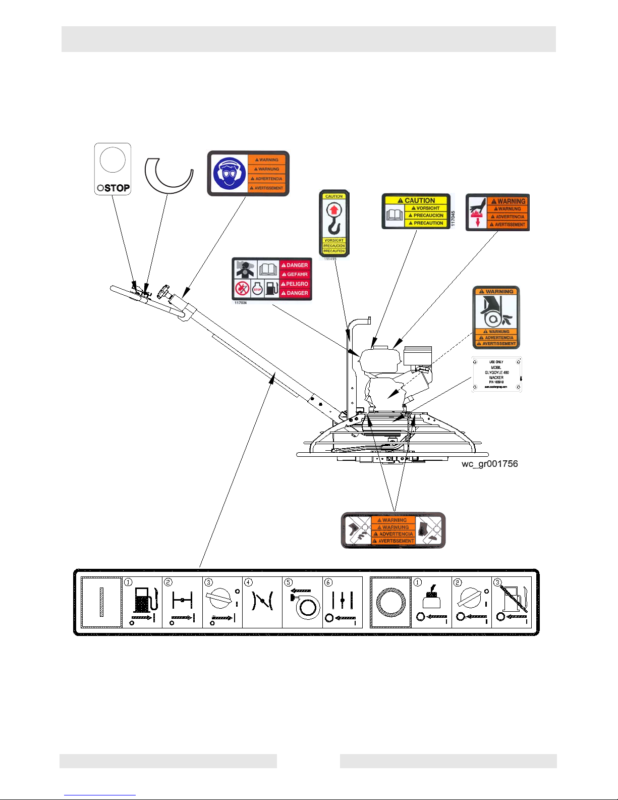
1.5 Label Locations
wc_si000139gb.fm 12
CT 36 / CT 48 Safety Information
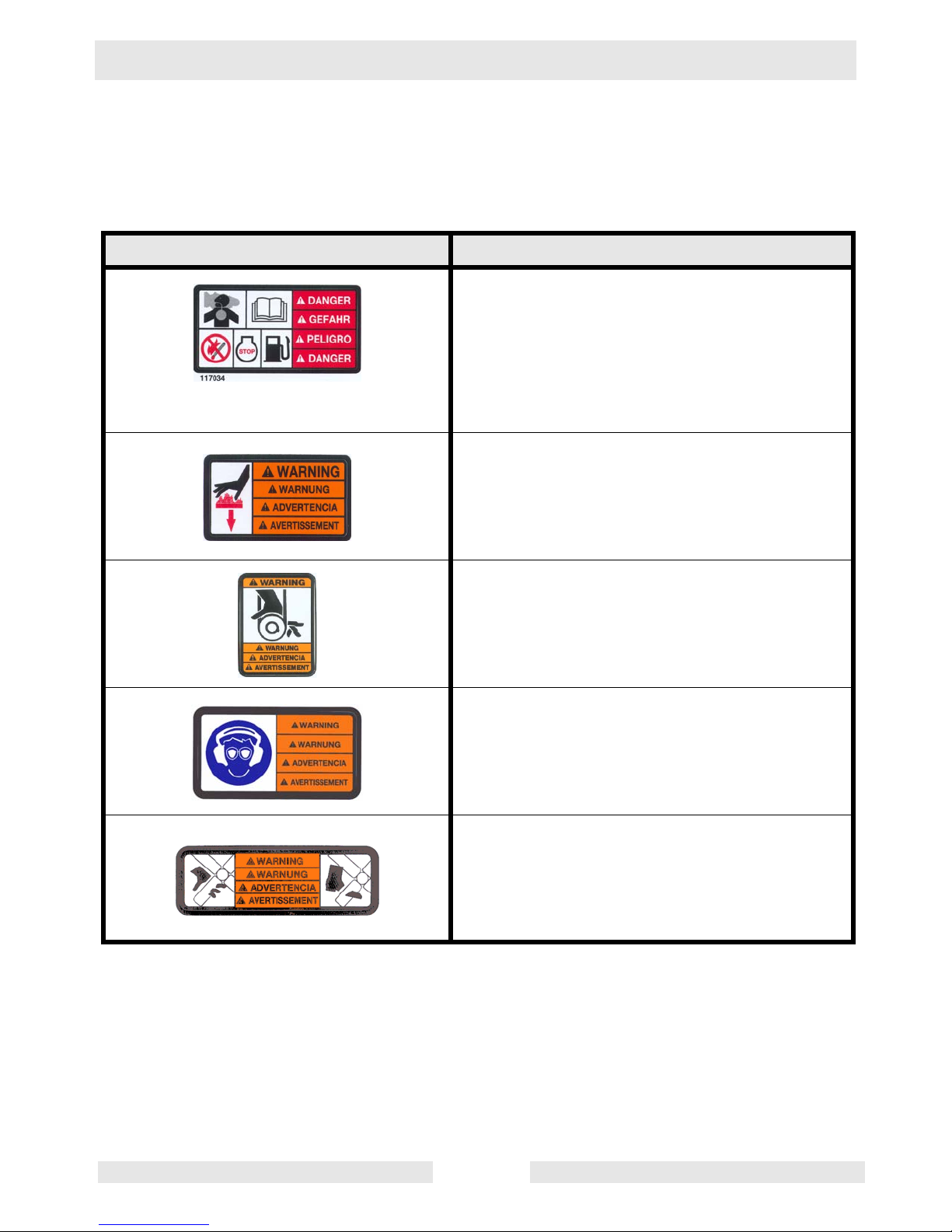
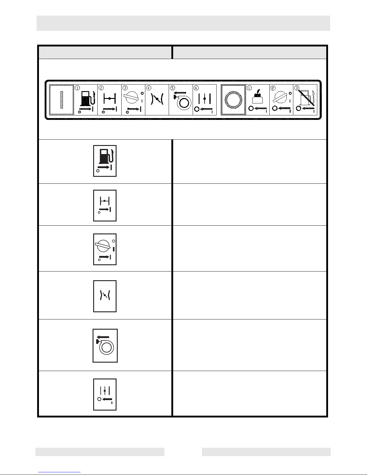
1.6 Safety and Information Labels
Wacker machines use international pictorial labels where needed.
These labels are described below:
Label Meaning
DANGER!
Engines emit carbon monoxide; operate only
in well-ventilated area. Read the Operator’s
Manual.
No sparks, flames, or burning objects near the
machine. Shut off the engine before refueling.
WARNING!
Hot surface!
WARNING!
Hand injury if caught in moving belt.
Always replace beltguard.
WARNING!
Always wear hearing and eye protection when
operating this machine.
WARNING!
Cutting hazard. Always replace blade guard!
wc_si000139gb.fm 13
Safety Information CT 36 / CT 48
Label Meaning
R e m o v e p a n f r o m t r o w e l b e f o r e l i f t i n g m a c h i n e
o v e r h e a d .
P a n s c a n f a l l a n d c a u s e d e a t h o r s e r i o u s i n j u r y i f
a p e r s o n i s h i t .
G l e i t s c h e i b e v o m B e t o n g l ä t t e r e n t f e r n e n b e v o r
d a s G e r ä t u b e r K o p f h ö h e g e h o b e n w i r d .
G l e i t s c h e i b e k a n n f a l l e n u n d s c h w e r e V e r l e t z u n g
o d e r T o d v e r u r s a c h e n w e n n P e r s o n a l g e t r o f f e n w i r d .
Q u i t e e l d i s c o d e f l o t a c i ó n a n t e s d e l e v a n t a r l a
m á q u i n a a l i s a d o r a d e h o r m i g ó n .
L o s d i s c o s p o d r í a n c a e r y m a t a r o l a s t i m a r
s e r i a m e n t e a u n a p e r s o n a q u e s e e n c u e n t r e c e r c a .
A v a n t d e l e v e r l a p p a r e i l a u - d e s s u s d e v o t r e t ê t e ,
ô t e r l e d i s q u e d e t a l o c h a g e d e l a t r u e l l e .
L e d i s q u e d e t a l o c h a g e p e u t t o m b e r e t e n t r a î n e r
d e g r a v e s b l e s s u r e s o u m ê m e l a m o r t .
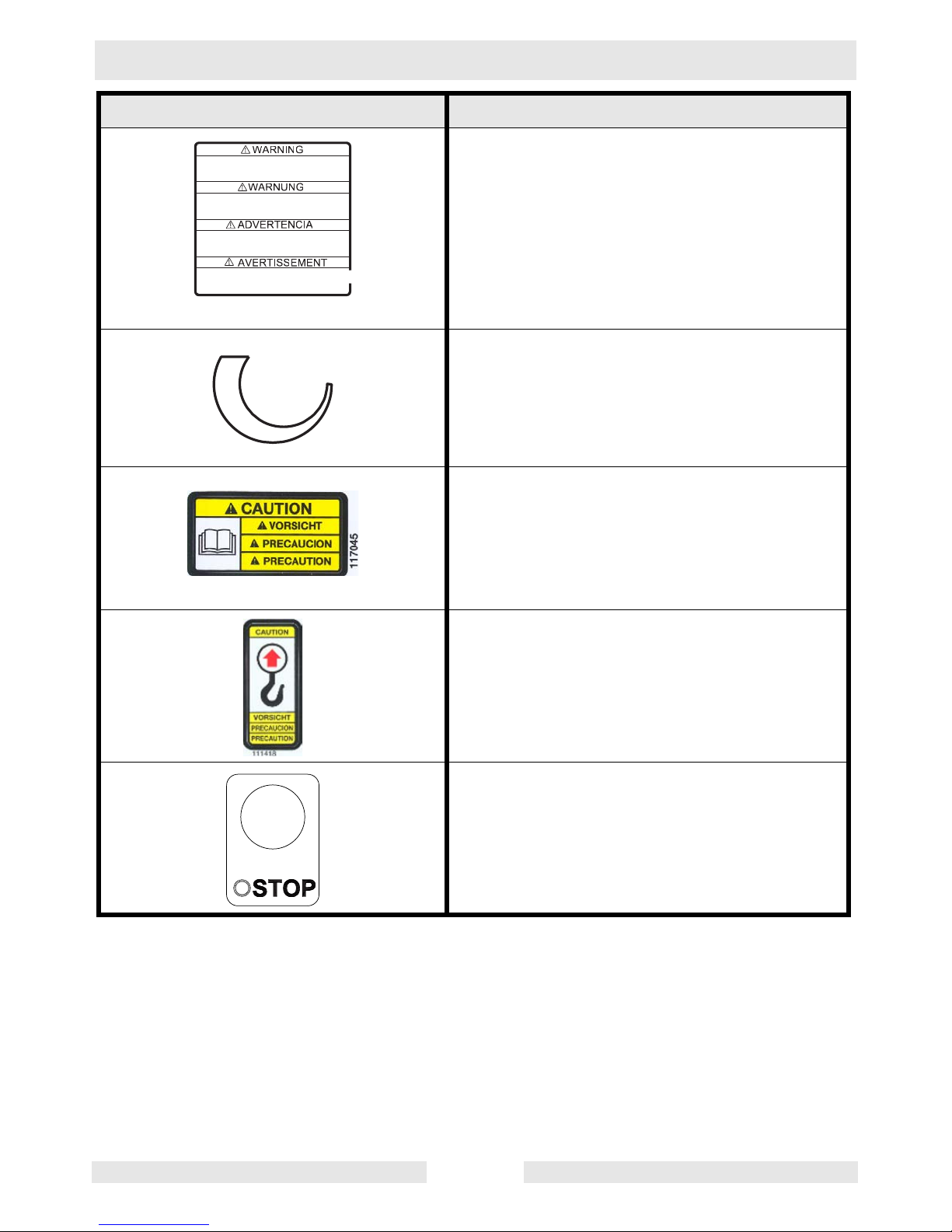
WARNING!
Remove pan from trowel before lifting machine
overhead. Pans can fall and cause death or
serious injury if a person is hit. (Located on top
side of float pan.)
1 1 8 6 8 8
Variable speed throttle
CAUTION!
Read and understand the supplied Operator’s
Manuals before operating this machine. Failure to do so increases the risk of injury to yourself or others.
CAUTION!
Lifting point.
Engine stop button:
Press to stop engine.
wc_si000139gb.fm 14
CT 36 / CT 48 Safety Information
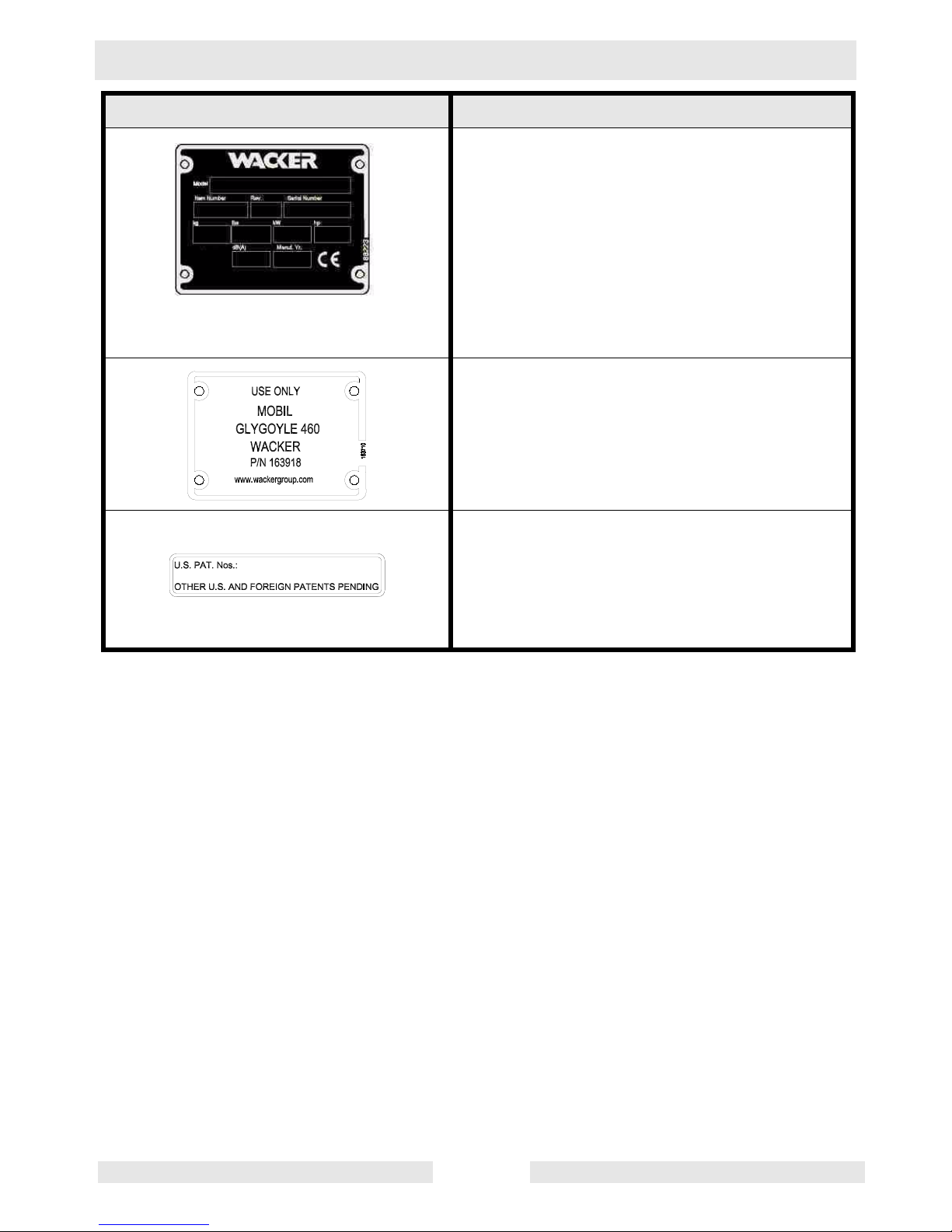
Label Meaning
A nameplate listing the model number, item
number, revision number, and serial number is
attached to each unit. Please record the information found on this plate so it will be available
should the nameplate become lost or damaged. When ordering parts or requesting service information, you will always be asked to
specify the model number, item number, revision number, and serial number of the unit.
Use only Glygoyle 460 gear oil in gearbox.
This machine may be covered by one or more
patents.
wc_si000139gb.fm 15
Safety Information CT 36 / CT 48
Label Meaning
Open the fuel flow valve.
Close the choke.
Turn engine key switch to “ON” position.
Place throttle in the IDLE position.
Pull the rewind starter.
Open the choke.
wc_si000139gb.fm 16
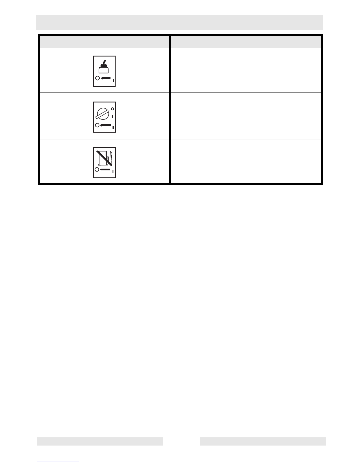
CT 36 / CT 48 Safety Information
Label Meaning
Press the stop button.
Turn engine key switch to “OFF” position.
Close the fuel flow valve.
wc_si000139gb.fm 17
Technical Data CT 36 / CT 48
2. Technical Data
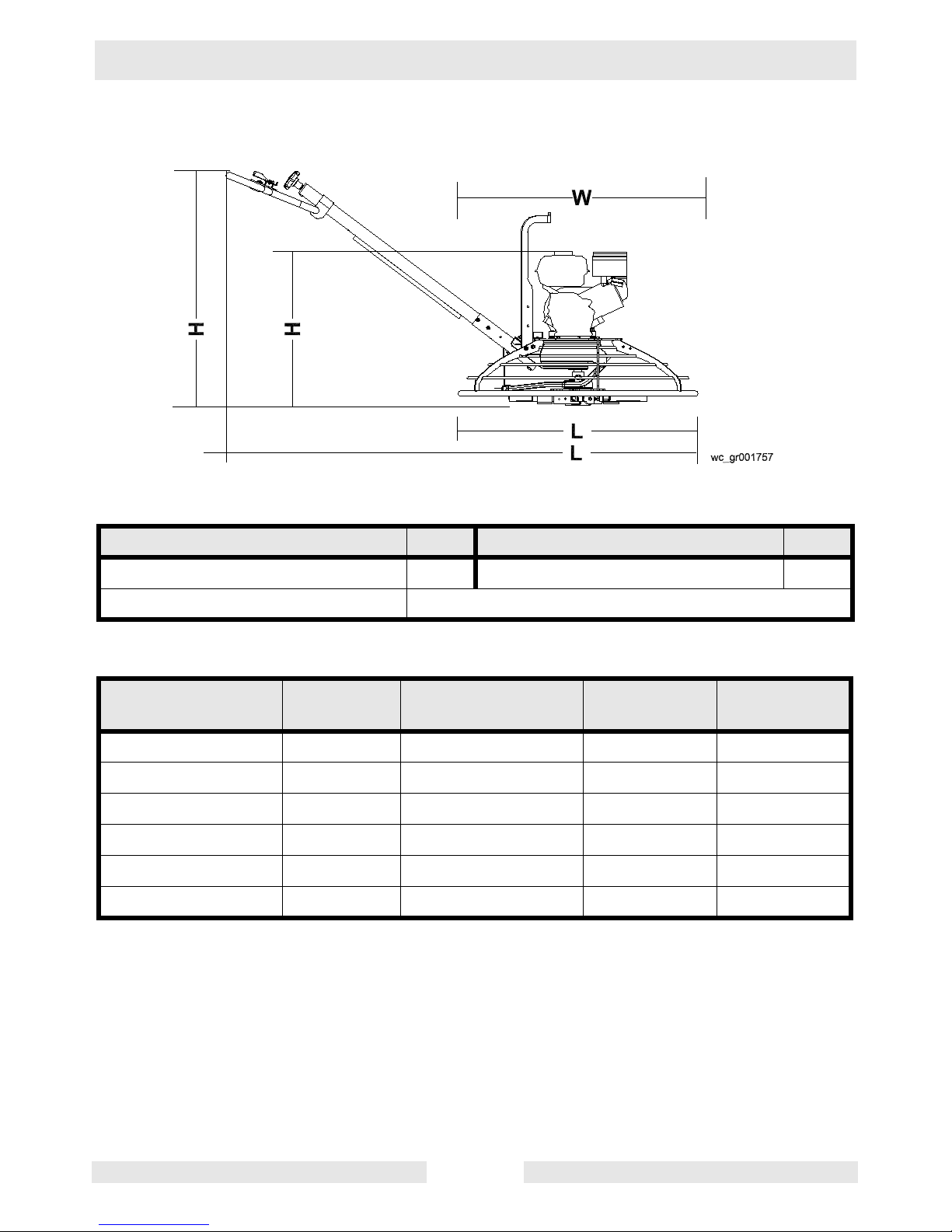
2.1 Dimensions and Weight
Guide
Description Ref. Description Ref.
Honda engine* A Variable Speed V
Engine Horse Power 4, 5, 6, 8, 9, 11, 13
*Standard models feature Wacker engine.
Handle Type Item No.
L
mm(in.)
Pitch
Type
Weight
kg (lbs.)
Solid 0159659 1740 (68.5) Twist 10 (21)
Folding 0159660 1740 (68.5) Twist 12 (26.5)
Adjustable/Folding 0164617 1740 (68.5) Twist 13 (28)
Adjustable 0164535 1740 (68.5) Twist 11 (24.5)
Adjustable/Folding 0159661 1740 (68.5) Pro-Shift® 15 (32.5)
Adjustable 0159662 1740 (68.5) Pro-Shift® 13 (29)
wc_td000141gb.fm 18

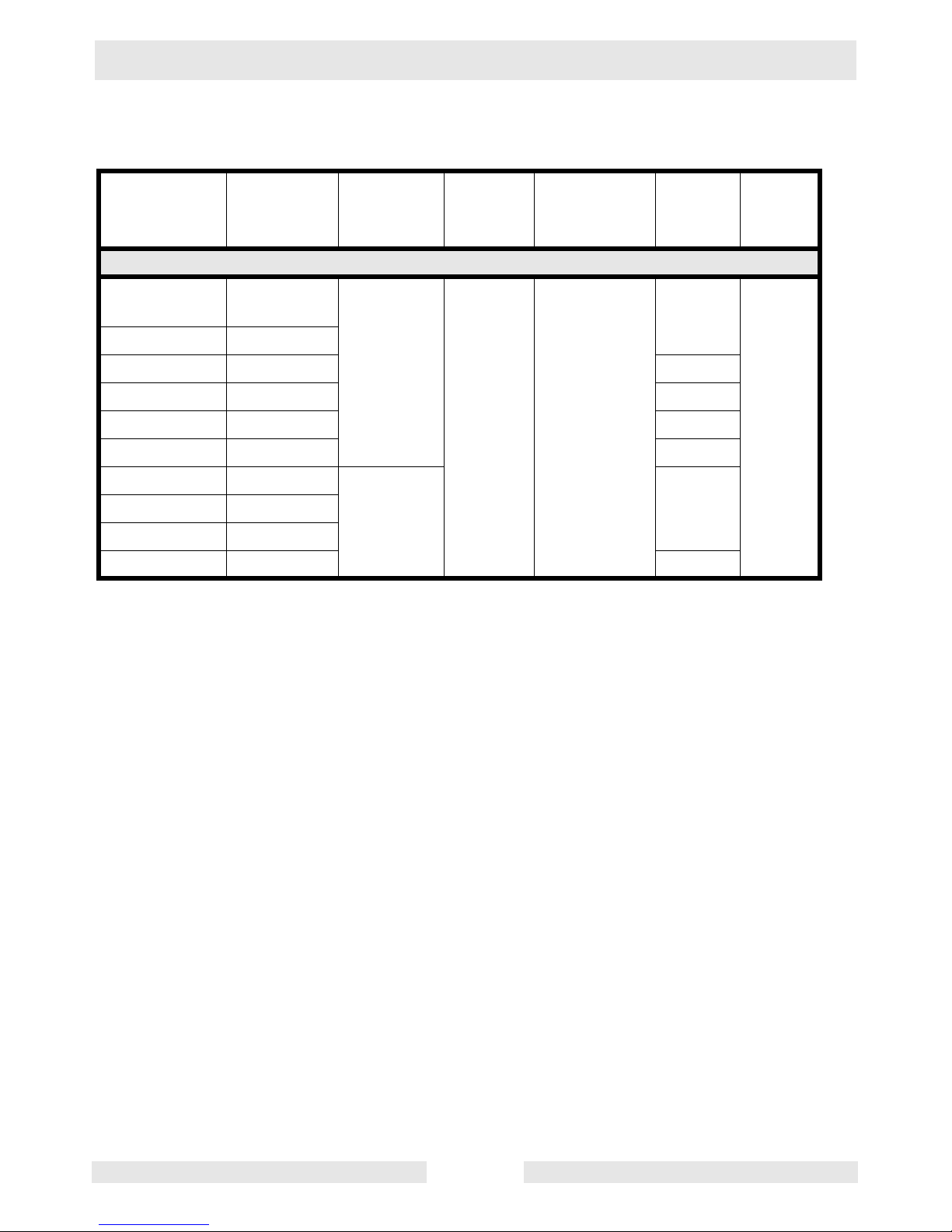
CT 36 / CT 48 Technical Data
without handle with handle
Model Item No.
CT 36-5A
0009438
0620106
CT 36-6 0009443
CT 36-8A 0009439
CT 36-8A-V 0009442
CT 36-9 0009444
CT 36-9-V 0009447
CT 48-8A 0009449
CT 48-9 0009453
LxWxH
mm
(in.)
915x915x607
(36x36x24)
915x915x607
(36x36x24)
915x915x686
(36x36x27)
915x915x686
(36x36x27)
915x915x686
(36x36x27)
915x915x686
(36x36x27)
1220x1220x686
(48x48x27)
1220x1220x686
(48x48x27)
LxWxH
mm
(in.)
2005x915x1040
(79x36x41)
2005x915x1040
(79x36x41)
2005x915x1040
(79x36x41)
2005x915x1040
(79x36x41)
2005x915x1040
(79x36x41)
2005x915x1040
(79x36x41)
2160x1220x1040
(85x48x41)
2160x1220x1040
(85x48x41)
without
weight kit
kg (lbs.)
with
weight kit
kg (lbs.)
85 (183) 91 (201)
85 (183) 91 (201)
94 (208) 103 (226)
94 (208) 103 (226)
90 (199) 98 (217)
90 (199) 98 (217)
105 (234) 114 (252)
105 (234) 114 (252)
CT 48-11A 0009450
CT 48-13A-V 0009452
1220x1220x712
(48x48x28)
1220x1220x712
(48x48x28)
2160x1220x1040
(85x48x41)
2160x1220x1040
(85x48x41)
113 (250) 122 (268)
121 (268) 130 (286)
wc_td000141gb.fm 19

Technical Data CT 36 / CT 48
2.2 Engine
Item No.
Engine Make
Engine Model
Rated Power
Spark Plug
Electrode Gap
Engine Speed - full load
Engine Speed - idle
Clutch engagement
Valve Clearance (cold)
intake:
exhaust:
Air Cleaner
Engine Lubrication
Engine Oil Capacity
Fuel
Fuel Tank Capacity
Fuel Consumption
Running time
kW (Hp)
mm (in.)
rpm
rpm
rpm
mm (in.)
type
oil grade
l (oz.)
type
l (qts.)
l (qts.)
/hr
hr.
CT 36-5A
0009438, 0620106
CT 36-6
0009443
Engine
Honda
GX 160 K1 QX2
4.3 (5.7) @ 3800rpm
NGK BPR 6ES NGK BR6HS
0.7 – 0.8 (0.028 – 0.031)
3800 ± 100
1450 ± 100
1800
0.15 (0.006)
0.20 (0.008)
Dual element
SAE 10W30 SG or SF SAE 10W30
0.6 (20)
Regular unleaded gasoline
3.6 (3.8)
1.8 (1.9) 1.52 (1.6)
22.4
4.2 (5.6) @ 3800 rpm
0.6–0.7 (0.024–0.028)
0.07–0.13 (0.0028–0.0051)
0.17–0.23 (0.0067–0.0091
Wacker
WM170
Champion RL86C
1400 ± 100
SE or higher
wc_td000141gb.fm 20

CT 36 / CT 48 Technical Data
Item No.
Engine Make
Engine Model
Rated Power
Spark Plug
Electrode Gap
Engine Speed - full load
Engine Speed - idle
Clutch engagement
Valve Clearance (cold)
intake:
exhaust:
Air Cleaner
Engine Lubrication
Engine Oil Capacity
Fuel
Fuel Tank Capacity
Fuel Consumption
Running time
kW (Hp)
mm (in.)
rpm
rpm
rpm
mm (in.)
type
oil grade
l (oz.)
type
l (qts.)
l (qts.)
/hr
hr.
CT 36-8A
0009439
CT 36-8A-V
0009442
CT36-9
0009444
CT 36-9-V
0009447
Engine
Honda Wacker
GX 240 K1 QA WM270
6.2 (8.3) @ 3800 rpm 6.5 (8.7) @ 3800 rpm
NGK BPR 6ES
0.7 – 0.8 (0.028 – 0.031)
3800 ± 100
1450 ± 100 1400 ± 100
1800
0.15 (0.006)
0.20 (0.008)
Dual element
SAE 10W30 SG or SF
1.1 (37)
Regular unleaded gasoline
6.0 (6.4)
2.7 (2.8) 2.5 (2.6)
2.25 2.4
NGK BR6HS
Champion RL86C
0.07–0.13 (0.0028–0.0051)
0.17–0.23 (0.0067–0.0091
SAE 10W30
SF, SE, SD, or SC
wc_td000141gb.fm 21

Technical Data CT 36 / CT 48
Item No.
Engine Make
Engine Model
Rated Power
Spark Plug
Electrode Gap
Engine Speed - full load
Engine Speed - idle
Clutch engagement
Valve Clearance (cold)
intake:
exhaust:
Air Cleaner
Engine Lubrication
Engine Oil Capacity
Fuel
Fuel Tank Capacity
Fuel Consumption
Running time
kW (Hp)
mm (in.)
rpm
rpm
rpm
mm (in.)
type
oil grade
l (oz.)
type
l (qts.)
l (qts.)
/hr
hr.
CT 48A-8A
0009449
CT 48-9
0009453
Engine
Honda Wacker
GX 240 K1 QA WM270
6.2 (8.3) @ 3800 rpm 6.5 (8.7) @ 3800 rpm
NGK BPR 6ES
0.7 – 0.8 (0.028 – 0.031)
3800 ± 100
1450 ± 100 1400 ± 100
1800
0.15 (0.006)
0.20 (0.008)
Dual element
SAE 10W30 SG or SF
1.1 (37)
Regular unleaded gasoline
6.0 (6.4)
2.7 (2.8) 2.5 (2.6)
2.25 2.4
NGK BR6HS
Champion RL86C
0.07–0.13 (0.0028–0.0051)
0.17–0.23 (0.0067–0.0091
SAE 10W30
SF, SE, SD, or SC
wc_td000141gb.fm 22

CT 36 / CT 48 Technical Data
Item No.
Engine Make
Engine Model
Rated Power
Spark Plug
Electrode Gap
Engine Speed - full load
Engine Speed - idle
Clutch engagement
Valve Clearance (cold)
intake:
exhaust:
Air Cleaner
Engine Lubrication
Engine Oil Capacity
Fuel
Fuel Tank Capacity
Fuel Consumption
Running time
kW (Hp)
mm (in.)
rpm
rpm
rpm
mm (in.)
type
oil grade
l (oz.)
type
l (qts.)
l (qts.)
/hr
hr.
CT 48-11A
0009450
CT 48-13A-V
0009452
Engine
Honda
GX 340 K1 QA GX 390 U1 QA
8.7 (11.6) @ 3800 rpm 10 (13.4) @ 3800 rpm
NGK BPR 6ES
0.7 – 0.8 (0.028 – 0.031)
3800 ± 100
1450 ± 100
1800
0.15 (0.006)
0.20 (0.008)
Dual element
SAE 10W30
SG or SF
1.1 (37)
Regular unleaded gasoline
6.0 (6.4)
2.7 (2.8)
2.25
wc_td000141gb.fm 23
Technical Data CT 36 / CT 48
2.3 Trowel
Model Item No.
Trowel
Diameter*
mm (in.)
Number
of
Blades
Gear Box
Lubrication
type/ml (oz.)
Speed
Range
rpm
Trowel
CT 36-5A
0009438
0620106
60–125
CT 36-6 0009443
CT 36-8A 0009439 60–125
CT 36-8A-V 0009442 25–200
CT 36-9 0009444 60–125
CT 36-9-V 0009447 25–200
CT 48-8A 0009449
915 (36)
Mobil
Glygoyle
4
460
Approx.
620 (21)
60–125CT 48-9 0009453
1220 (48)
CT 48-11A 0009450
CT 48-13A-V 0009452 25–200
*Trowel blades must NOT be interchanged, i.e., do NOT put larger diameter blades on a smaller
diameter trowel.
Pitch
Range
degrees
0–30
wc_td000141gb.fm 24

CT 36 / CT 48 Technical Data
2.4 Sound and Vibration Data
The required sound specification, Paragraph 1.7.4.f of 89/392/EEC
Machinery Directive, is:
• the sound pressure level at operator’s location (L
• the guaranteed sound power level (L
) = “B” dB(A)
WA
) : “A” dB(A)
pA
These sound values were determined according to ISO 3744 for the
sound power level (LWA) and ISO 6081 for the sound pressure level
(LpA) at the operator’s location.
• The weighted effective acceleration value, determined according to
ISO 8662 Part 1, is: “C” m/s2.
The sound and vibration specifications were obtained with the unit
operating on wetted and cured concrete at full engine speed.
Model Item No. A B C
CT 36-5A
0009438
0620106
103 89 5.3
CT 36-6 0009443 103 89 5.3
CT 36-8A 0009439 109 95 4.3
CT 36-8A-V 0009442 109 95 4.0
CT 36-9 0009444 109 95 7.1
CT 36-9-V 0009447 109 95 6.6
CT 48-8A 0009449 109 95 5.3
CT 48-9 0009453 109 95 5.3
CT 48-11A 0009450 113 96 7.1
CT 48-13A-V 0009452 115 98 4.1
wc_td000141gb.fm 25

Operation CT 36 / CT 48
3. Operation
3.1 Application
This trowel is a modern, high production machine intended for floating
and finishing freshly poured concrete slabs. The machine's good
balance, adjustable handle, and easily reached controls add to
operator comfort and productivity. An automatic stop sensor provides
added operator safety. Finishing rates will depend on operator skill and
job conditions.
DO NOT use this machine for any application other than troweling
concrete.
3.2 New Machine Set-up
Trowels are shipped from the factory with the handle removed. Follow
instructions on Installing Blades and Installing and Adjusting Handles
when setting up new machines or when installing new handles and
blades.
3.3 Recommended Fuel
The engine requires regular grade unleaded gasoline. Use only fresh,
clean gasoline. Gasoline containing water or dirt will damage fuel
system. Consult engine Owner’s Manual for complete fuel
specifications.
wc_tx000373gb.fm 26
CT 36 / CT 48 Operation
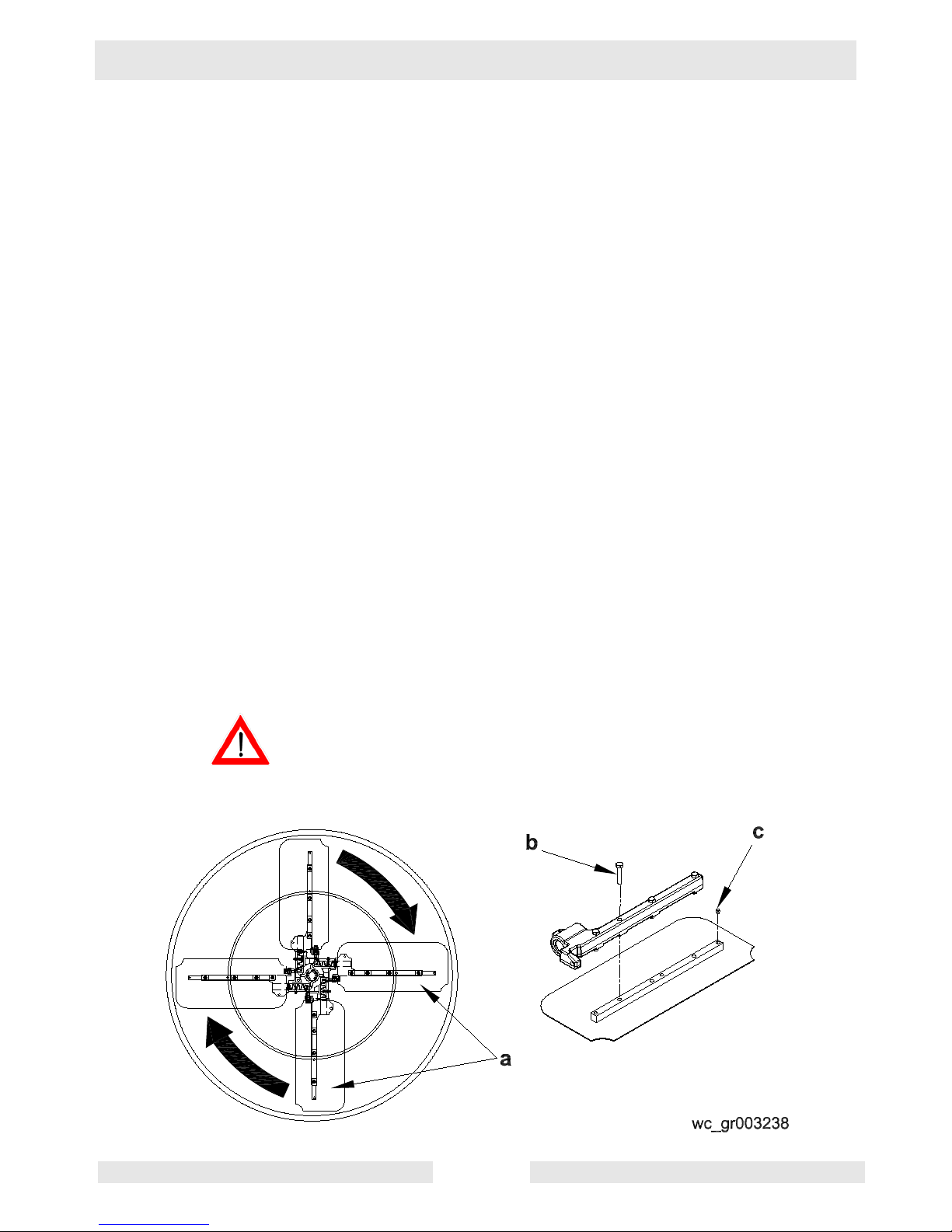
3.4 Installing Blades
See Graphic: wc_gr003238
There are four types of blades available for the trowels. Float pans are
large "pizza pan" style blades, which hook on over finish or
combination blades and are available for the 36" machines only. Float
blades are available for all machines and clip on over finish or
combination blades. Both are used in the earliest stages of work, and
are not pitched.
Finish blades are used in the final stages of working, and are
progressively pitched to burnish the concrete.
Combination blades can be used throughout the concrete working
process. They are used in place of float blades or pans and finish
blades.
Note: Trowel blades must NOT be interchanged, i.e., do NOT put
larger diameter blades on a smaller diameter trowel.
3.4.1 Finish blades are flat on both edges and can be installed in either
direction.
When installing combination blades, orient blades as shown (a). This
positions the raised edges of the blade correctly for the clockwise
rotation of the machine.
3.4.2 Secure blades to trowel arms with screws (b). Dip threads of screws in
grease prior to installation. This will prevent concrete from cementing
the screws in place and will make removal of the blades easier later on.
3.4.3 Plug the remaining threaded holes in the blade brace with plastic plugs
(c) to prevent them from filling with concrete.
Do not lift the trowel overhead with a float pan attached, as the pan
could fall off and strike personnel working in the vicinity.
WARNING
wc_tx000373gb.fm 27

Operation CT 36 / CT 48
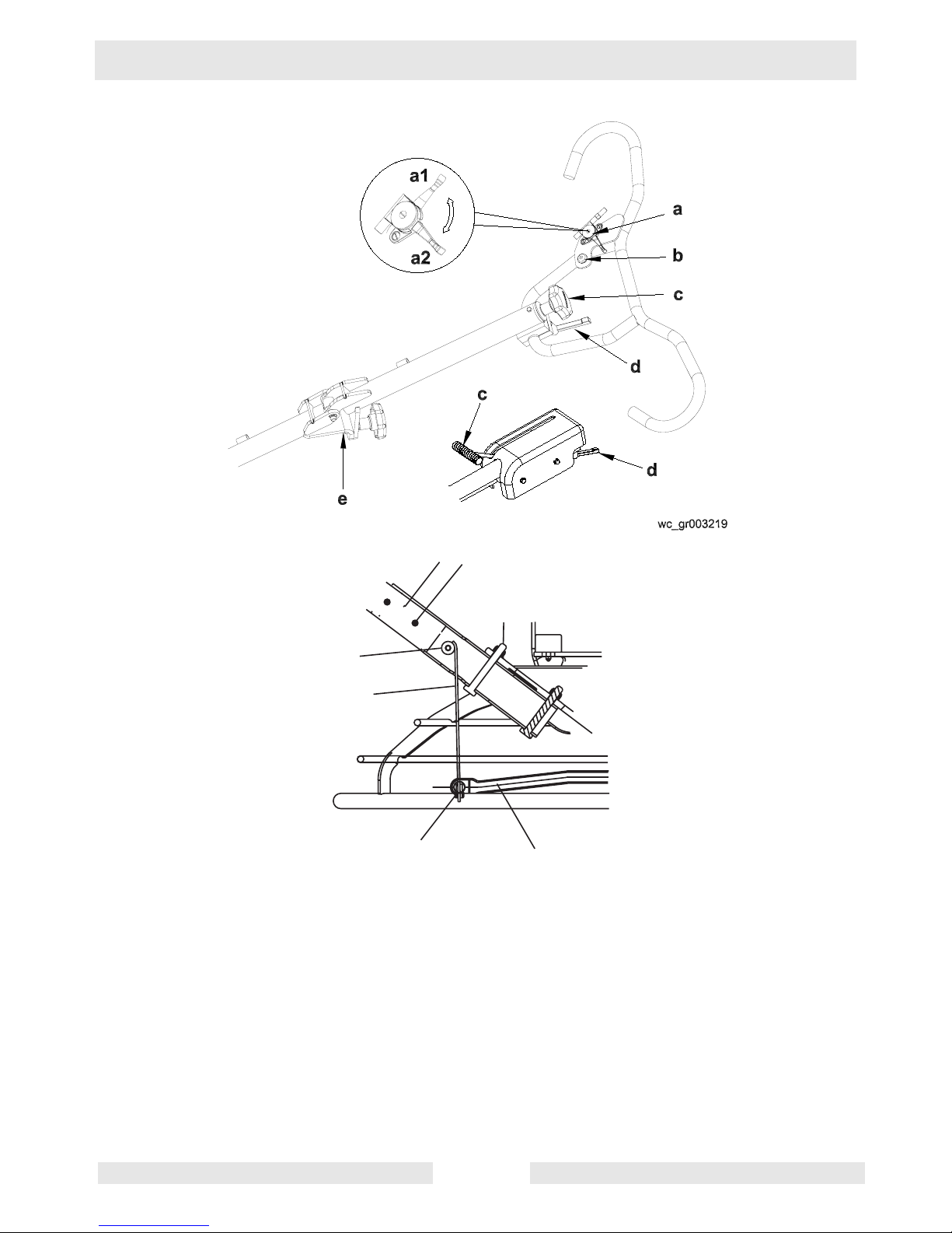
3.5 Installing and Adjusting Handles
See Graphic: wc_gr001758, wc_gr003219
On new machines the pipe handle comes assembled with the pitch
control (Twist or Pro-Shift®) (c), stop button (b), throttle (a), screws
(g), and nut (m).
To install the pipe handle assembly:
3.5.1 On machines with the foldable handle, straighten the handle and
tighten the knob (e) to secure the handle in position.
3.5.2 Pull the pitch control cable (j) from bottom end of the tube and remove
the nut from the cable.
3.5.3 Thread the cable through the handle base (f) and over the pulley (h)
as shown.
3.5.4 Attach the pipe handle to the handle base with two M8x65 screws (g).
Torque the screws to 25 Nm (18 ft.lbs.).
3.5.5 Push the Pro-Shift® handle all the way forward (away from the
operator) OR turn the twist pitch control handle counterclockwise as far
as possible. Connect the cable to the fork (k) as shown and adjust the
cable nut (m) so the cable is snug and the trowel blades lay flat (0°
pitch).
3.5.6 Move throttle (a1) to idle position. Remove air cleaner cover. Feed
cable through clamp on recoil cover. Connect throttle cable to engine
throttle bracket by placing z-bend through hole in throttle plate. Clamp
cable into throttle casing bracket. Replace air cleaner cover.
3.5.7 Connect electrical wire on handle to both ends of the engine wire. See
handle instruction sheet for additional detail on installation.
Note: On machines with Wacker engines, do not connect wires in bag
to wires in handle.
3.5.8 On machines with an adjustable handle, position the handle by
loosening the knob (d) and adjusting the handle up or down to suit the
operator. Tighten the knob to secure the handle in position.
wc_tx000373gb.fm 28
CT 36 / CT 48 Operation
e
f
g
h
wc_gr001758
k
j
wc_tx000373gb.fm 29
Operation CT 36 / CT 48
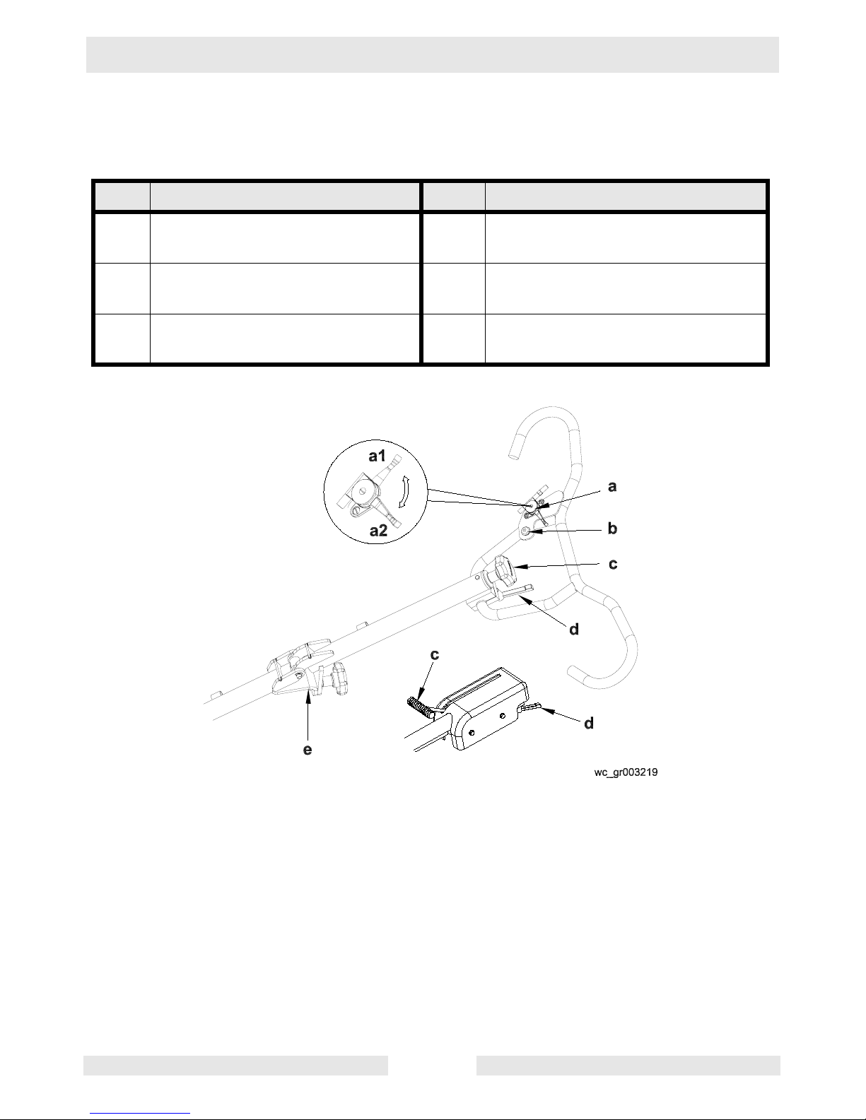
3.6 Controls
See Graphic: wc_gr003219
Ref. Description Ref. Description
a Throttle lever d Handle height adjustment (if
equipped)
b Stop button e Foldable handle adjustment (if
equipped)
c Twist pitch control or Pro-Shift®
pitch control
wc_tx000373gb.fm 30
 Loading...