

Page 1

Operator’s Manual
5000184477
Trowel
CT24-4A
Type
Document 5000184477
Date
Version
Language EN
CT24-4A
0917
12
Page 2

Copyright notice
© Copyright 2017 by Wacker Neuson Production Americas LLC
All rights, including copying and distribution rights, are reserved.
This publication may be photocopied by the original purchaser of the
machine. Any other type of reproduction is prohibited without express
written permission from Wacker Neuson Production Americas LLC.
Any type of reproduction or distribution not authorized by Wacker
Neuson Production Americas LLC represents an infringement of valid
copyrights. Violators will be prosecuted.
Trademarks
Manufacturer
Original instructions
All trademarks referenced in this manual are the property of their
respective owners.
Wacker Neuson Production Americas LLC
N92W15000 Anthony Avenue
Menomonee Falls, WI 53051 U.S.A.
Tel: (262) 255-0500 · Fax: (262) 255-0550 · Tel: (800) 770-0957
www.wackerneuson.com
This Operator’s Manual presents the original instructions. The original
language of this Operator’s Manual is American English.
Page 3

CT 24-4A Foreword
Foreword
SAVE THESE INSTRUCTIONS—This manual contains important instructions for
the machine models below. These instructions have been written expressly by
Wacker Neuson Production Americas LLC and must be followed during inst allation,
operation, and maintenance of the machines.
Machine Item Number
CT 24-24A 0620105, 0620849
Machine
identification
Serial number
(S/N)
Machine
documentation
wc_gr010143
A nameplate listing the model number, item number, revision number, and serial
number is attached to this machine. The location of the nameplate is shown above.
For future reference, record the serial number in the space provided below . You will
need the serial number when requesting parts or service for this machine.
Serial Number:
From this point forward in this documentation, Wacker Neuson Production
Americas L
Keep a copy of the Operator’s Manual with the machine at all times.
Use the separate Parts Book supplied with the machine to order replacement
rts.
pa
If you are missing either of these documents, please conta ct W acker Neuson to
LC will be referred to as Wacker Neuson.
order a replacement or visit www.wackerneuson.com.
When ordering parts or requesting service information, be prepared to provide
e machine model number, item number, revision number, and serial number.
th
wc_tx003230gb.fm 3
Page 4

Foreword CT 24-4A
Expectations
for
information in
this manual
Manufacturer’s
approval
This manual provides information and procedures to safely operate and
maintain the above Wacker Neuson model(s). For your own safety and to
reduce the risk of injury , carefully read, underst and, and observe all instructions
described in this manual.
Wacker Neuson expressly reserves the right to make technical modifications,
even without notice, which improve the performance or safety standards of its
machines.
The information contained in this manual is based on machines manufactured
up until the time of publication. Wacker Neuson reserves the right to change
any portion of this information without notice.
The illustrations, parts, and procedures in this manual refer to Wacker Neuson
factory-installed components. Your machine may vary depending on the
requirements of your specific region.
This manual contains references to approved parts, attachments, and modifications. The following definitions apply:
Approved parts or attachments are those either manufactured or provided by
Wacker Neuso
Approved modifications are those performed by an authorized Wacker
Neuson service center according to written instructions published by Wa
son.
Neu
Unapproved parts, attachments, and modifications are those that do not
n.
cker
meet the approved criteria.
Unapproved parts, attachments, or modifications may have the following consequences:
Serious injury hazards to the operator and persons in the work area
Permanent damage to the machine which will not be covered under warranty
Contact your Wacker Neuson dealer immediately if you have questions abo
approved or
unapproved parts, attachments, or modifications.
ut
CALIFORNIA
Proposition
65 Warning
Laws
pertaining to
spark
arresters
Combustion exhaust, some of its constituents, and certain vehicle components
contain or emit chemicals known to the State of California to cause cancer and
birth defects or other reproductive harm.
NOTICE: State Health Safety Codes and Public Resources Codes specify that in
certain locations spark arresters be used on internal combustion engines that use
hydrocarbon fuels. A spark arrester is a device designed to prevent accidental discharge of sparks or flames from the engine exhaust. Spark arresters are qualified
and rated by the United States Forest Service for this purpose. In order to comply
with local laws regarding spark arresters, consult the engine distributor or the local
Health and Safety Administrator.
4 wc_tx003230gb.fm
Page 5

EC Declaration of Conformity
Manufacturer
Wacker Neuson Production Americas LLC, N92W15000 Anthony Avenue,
Menomonee Falls, Wisconsin 53051, USA
Product
Product
Product category
Product function
Item number
CT24-4A
Trowel
To smooth and finish semi-cured concrete
5000620849
Directives and Standards
We hereby declare that this product meets and complies with the relevant regulations and
requirements of the following directives and standards:
2006/42/EC, 2014/30/EU, EN12649
Authorized Person for Technical Documents
Robert Raethsel, Wacker Neuson Produktion GmbH & Co. KG, Wackerstrasse 6, 85084
Reichertshofen, Germany
Menomonee Falls, WI, USA, 24.06.16
Keith Herr
Vice President and Managing Director
For Wacker Neuson
2016_CE_CT24-4A_en_FM10.fm
Jeff Volden
Director, Product Engineering
For Wacker Neuson
Scott Grahl
Manager, Product Engineering
For Wacker Neuson
Original Declaration of Conformity
Page 6

Page 7

CT 24-4A
Table of Contents
Foreword 3
EC Declaration of Conformity 5
1 Safety Information 9
1.1 Signal Words Used in this Manual ....................................................... 9
1.2 Machine Description and Intended Use ............................................. 10
1.3 Safety Guidelines for Operating the Machine ..................................... 11
1.4 Service Safety .................................................................................... 13
1.5 Operator Safety while Using Internal Combustion Engines ............... 15
2 Labels 16
2.1 Label Locations .................................................................................. 16
2.2 Label Meanings .................................................................................. 17
3 Lifting and Transporting 20
3.1 Lifting the Machine ............................................................................. 20
3.2 Transporting the Machine ................................................................... 21
4 Operation 22
4.1 Preparing the Machine for First Use ................................................... 22
4.2 New Machine Set-Up ......................................................................... 22
4.3 Recommended Fuel ........................................................................... 23
4.4 Refueling the Machine ........................................................................ 24
4.5 Installing Blades ................................................................................. 25
4.6 Unfolding Handle ................................................................................ 26
4.7 Controls .............................................................................................. 27
4.8 Operator Present Lever ...................................................................... 27
4.9 Before Starting ................................................................................... 28
4.10 Starting ............................................................................................... 28
4.11 Stopping ............................................................................................. 29
4.12 Position of the Operator ..................................................................... 30
4.13 Operation ............................................................................................ 30
4.14 Emergency Shutdown Procedure ....................................................... 31
4.15 Pitch Adjustment ................................................................................ 32
wc_bo5000184477_12TOC.fm
7
Page 8

Table of Contents
CT 24-4A
5 Maintenance 33
5.1 Maintaining the Emission Control System ...........................................33
5.2 Periodic Maintenance Schedule ..........................................................33
5.3 Engine Oil ............................................................................................34
5.4 Servicing the Air Cleaner .....................................................................35
5.5 Spark Plug ...........................................................................................36
5.6 Cleaning the Sediment Cup ................................................................37
5.7 Adjusting the Idle Speed .....................................................................38
5.8 Carburetor Adjustment ........................................................................39
5.9 Belt Replacement ................................................................................40
5.10 Trowel Lubrication ...............................................................................41
5.11 Storage ................................................................................................42
6 Troubleshooting 43
7 Technical Data 44
7.1 Dimensions and Weights .....................................................................44
7.2 Engine .................................................................................................45
7.3 Trowel ..................................................................................................46
7.4 Sound and Vibration Specifications .....................................................47
8 Emission Control Systems Information and Warranty 48
8.1 Emission Control Systems Warranty Statement .................................48
9 AEM Safety Manual 49
8
wc_bo5000184477_12TOC.fm
Page 9
CT 24-4A Safety Information
1 Safety Information
1.1 Signal Words Used in this Manual
is manual contains DANGER, WARNING, CAUTION, NOTICE, and NOTE
Th
signal words which must be followed to reduce the possibility of personal injury,
damage to the equipment, or improper service.
This is the safety alert symbol. It is used to alert you to potential personal hazards.
f Obey all safety messages that follow this symbol.
DANGER
DANGER indicates a hazardous situation which, if not avoided, will result in death
or serious injury.
f To avoid death or serious injury from this type of hazard, obey all safety
messages that follow this signal word.
WARNING
WARNING indicates a hazardous situation which, if not avoided, could result in
death or serious injury.
f To avoid possible death or serious injury from this type of hazard, obey all safety
messages that follow this signal word.
CAUTION
CAUTION indicates a hazardous situation which, if not avoided, could result in
minor or moderate injury.
f To avoid possible minor or moderate injury from this type of hazard, obey all
safety messages that follow this signal word.
NOTICE: Used without the safety alert symbol, NOTICE indicates a situation
which, if not avoided, could result in property damage.
Note: A Note contains additional information important to a procedure.
wc_si000741gb.fm
9
Page 10

Safety Information CT 24-4A
1.2 Machine Description and Intended Use
This machine is a walk-behind concrete finishing trowel. The Wacker Neuson
Walk-Behind Trowel consists of a frame onto which are mounted a gasoline
engine, a fuel tank, a gearbox, and a control handle. A set of four metal blades is
connected to the gearbox and is surrounded by a ring guard. The engine rotates
the blades through the gearbox and clutch mechanism. The rotating blades ride on
the surface of curing concrete, creating a smooth finish. The operator walks behind
the machine and uses the handle to control speed and direction of the machine.
This machine is intended to be used for floating and burnishing curing concrete.
This machine has been designed and built strictly for the intended use described
above. Using the machine for any other purpose could permanently damage the
machine or seriously injure the operator or other persons in the area. Machine
damage caused by misuse is not covered under warranty.
The following are some examples of misuse:
Using the machine as a ladder, support, or work surface
Using the machine to carry or transport passengers or equipment
Using the machine to finish inappropriate materials such as slurries, sealers, or
epoxy finishes
Operating the machine outside of factory specifications
Operating the machine in a manner inconsistent with all warnings found on the
machine and in the Operator’s Manual
This machine has been designed and built in accordance with the latest global
safety standards. It has been carefully engineered to eliminate hazards as far as
practicable and to increase operator safety through protective guards and labeling.
However, some risks may remain even after protective measures have been taken.
They are called residual risks. On this machine, they may include exposure to:
Heat, noise, exhaust, and carbon monoxide from the engine
Chemical burns from curing concrete
Fire hazards from improper refueling techniques
Fuel and its fumes, fuel spillage from improper lifting technique
Personal injury from improper lifting techniques or operating techniques
Cutting hazards from sharp or worn blades
To protect yourself and others, make sure you thoroughly read and understand the
safety information presented in this manual before operating the machine.
10
wc_si000741gb.fm
Page 11

CT 24-4A Safety Information
1.3 Safety Guidelines for Operating the Machine
Operator
training
Operator
qualifications
Application
area
Before operating the machine:
Read and understand the operating instructions contained in all manuals
delivered with the machine.
Familiarize yourself with the locat ion and proper use of all controls and safety
devices.
Contact Wacker Neuson for additional training if necessary.
When operating this machine:
Do not allow improperly trained people to operate the machine. People
operating the machine must be familiar with the potential ri sks and hazards
associated with it.
Only trained personnel are permitt ed to start , operate, and shut down the machi ne.
They also must meet the following qualificat ions:
have received instruction on how to properly use the machine
are familiar with required safety devices
The machine must not be accessed or operated by:
children
people impaired by alcohol or drugs
Be aware of the application area.
Keep unauthorized personnel, children, and pets away from the machine.
Remain aware of changing positions and the movement of ot her equipment and
personnel in the application area/job site.
Identify whether special hazards exist in the application area, such as toxic
gases, or unstable ground conditions, and take appropriate action to eliminate
the special hazards before using the machine.
Dust
precaution
wc_si000741gb.fm
Be aware of the application area.
Do not operate the machine in areas that contain flammable obj ects, fuels, or
products that produce flammable vapors.
Dust created by construction activities may cause silicosis or respiratory harm. To
reduce the risk of exposure:
Work in a well ventilated area
Use a dust control system
Wear an approved dust/particle respirator
11
Page 12

Safety Information CT 24-4A
Safety
devices,
controls, and
attachments
Safe
operating
practices
Only operate the machine when:
All safety devices and guards are in place and in working order.
All controls operate correctly.
The machine is set up correctly according to the instructions in the Operator’s
Manual.
The machine is clean.
The machine’s labels are legible.
To ensure safe operation of the machine:
Do not operate the machine if any safety devices or guards are missing or
inoperative.
Do not modify or defeat the safety devices.
Only use accessories or attachments that are approved by Wacker Neuson.
When operating this machine:
Remain aware of the machine’s moving parts. Keep hands, feet, and loos e
clothing away from the machine’s moving parts.
When operating this machine:
Do not operate a machine in need of repair.
Do not operate the machine with the beltguard missing. Exposed drive belt and
pulleys create potentially danger ous hazards that can cause serious injuries.
Do not use the trowel around pop-ups in the concrete that are lower than the
lowest ring on the ring guard.
Do not lift the machine solely by the handle. The component may fail, causing
the machine to fall, possibly injur ing bystanders.
Test the function of the engine control module before operating the trowel. Do
not operate the trowel if the engine control module is not functi oning properly.
Personal
Protective
Equipment
(PPE)
After Use
Wear the following Personal Protective Equipment (PPE) while operating this
machine:
Close-fitting work clothes that do not hinder movement
Safety glasses with side shields
Hearing protection
Safety-toed footwear
Stop the engine when the machine is not being operated.
Close the fuel valve on engines equipped with one when the machine is not
being operated.
Ensure that the machine will not tip over, roll, slide, or fall when not being
operated.
Store the machine properly when it is not being used. The machine should be
stored in a clean, dry location out of the reach of children.
wc_si000741gb.fm
12
Page 13

CT 24-4A Safety Information
1.4 Service Safety
Service
training
Precautions
Before servicing or maintaining the machine:
Read and understand the instructions contained in all manuals delivered with
the machine.
Familiarize yourself with the location and proper use of all controls and safety
devices.
Only trained personnel shall troubleshoot or repair problems occurring with the
machine.
Contact Wacker Neuson for additional training if necessary.
When servicing or maintaining this machine:
Do not allow improperly trained people to service or maintain the machine.
Personnel servicing or maintaining the machine must be familiar with the
associated potential risks and hazards.
Follow the precautions below when servicing or maintaining the machine.
Read and understand the service procedures before performing any service to
the machine.
All adjustments and repairs must be completed before operation. Do not
operate the machine with a known problem or deficiency.
All repairs and adjustments shall be completed by a qualified technician.
Turn off the machine before performing maintenance or making repairs.
Machine
modifications
Replacing
parts and
labels
Cleaning
When servicing or maintaining the machine:
Use only accessories/attachments that are approved by Wacker Neuson.
When servicing or maintaining the machine:
Do not defeat safety devices.
Do not modify the machine without the express written approval of Wacker
Neuson.
Replace worn or damaged components.
Replace all missing and hard-to-read labels.
When replacing electrical components, use components that are identical in
rating and performance to the original components.
When replacement parts are required for this machine, use only Wacker
Neuson replacement parts or those p arts equivalent to the original in a ll types of
specifications, such as physical dimensions, type, strength, and material.
When cleaning and servicing the machine:
Keep the machine clean and free of debris such as leaves, paper, cartons, etc.
Keep the labels legible.
When cleaning the machine:
Do not clean the machine while it is running.
Never use gasoline or other types of fuels or flammable solvents to clean the
machine. Fumes from fuels and solvents can become explosive.
wc_si000741gb.fm
13
Page 14

Safety Information CT 24-4A
Personal
Protective
Equipment
(PPE)
Safe service
practices
Wear the following Personal Protective Equipment (PPE) while servicing or
maintaining this machine:
Close-fitting work clothes that do not hinder movement
Safety glasses with side shields
Hearing protection
Safety-toed footwear
In addition, before servicing or maintaining the machine:
Tie back long hair.
Remove all jewelry (including rings).
Do not crank a flooded engine with the spark plug removed on gasoline-
powered engines. Fuel trapped in the cylinder will squirt out the spark plug
opening.
Do not test for spark on gasoline-powered engines if the engine is flooded or the
smell of gasoline is present. A stray spark could ignite the fumes.
Disconnect the spark plug on machines equipped with gasoline engines, before
servicing, to avoid accidental start-up.
Do not remove blades while the machine is hanging overhead.
Support the machine securely before changing blades.
Handle blades carefully. The blades can develop sharp edges which can cause
serious cuts.
14
wc_si000741gb.fm
Page 15

CT 24-4A Safety Information
1.5 Operator Safety while Using Internal Combustion Engines
WARNING
Internal combustion engines present special hazards during operation and fueling.
Failure to follow the warnings and safety standards could result in severe injury or
death.
f Read and follow the warning instructions in the engine owner’s manual and the
safety guidelines below.
DANGER
Exhaust gas from the engine contains carbon monoxide, a deadly poison.
Exposure to carbon monoxide can kill you in minutes.
f NEVER operate the machine inside an enclosed area, such as a tunnel, unless
adequate ventilation is provided through such items as exhaust fans or hoses.
Operating
safety
Refueling
safety
When running the engine:
Keep the area around exhaust pipe free of flammable materials.
Check the fuel lines and the fuel tank for leaks and cracks before starting the
engine. Do not run the machine if fuel leaks are present or the fuel lines are
loose.
When running the engine:
Do not smoke while operating the machine.
Do not run the engine near sparks or open flames.
Do not touch the engine or muffler while the engine is running or immediately
after it has been turned off.
Do not operate a machine when its fuel cap is loose or missing.
Do not start the engine if fuel has spilled or a fuel odor is present. Move the
machine away from the spill and wipe the machine dry before starting.
When refueling the engine:
Clean up any spilled fuel immediately.
Refill the fuel tank in a well-ventilated area.
Reinstall the fuel tank cap after refueling.
Do not smoke.
Do not refuel a hot or running engine.
Do not refuel the engine near sparks or open flames.
Use suitable tools for refueling (for example, a fuel hose or funnel).
Do not refuel if the machine is positioned in a truck fitted with a plastic bed liner.
Static electricity can ignite the fuel or fuel vapors.
wc_si000741gb.fm
15
Page 16

Labels CT 24-4A
2 Labels
2.1 Label Locations
16 wc_si000742gb.fm
Page 17
CT 24-4A Labels
2.2 Label Meanings
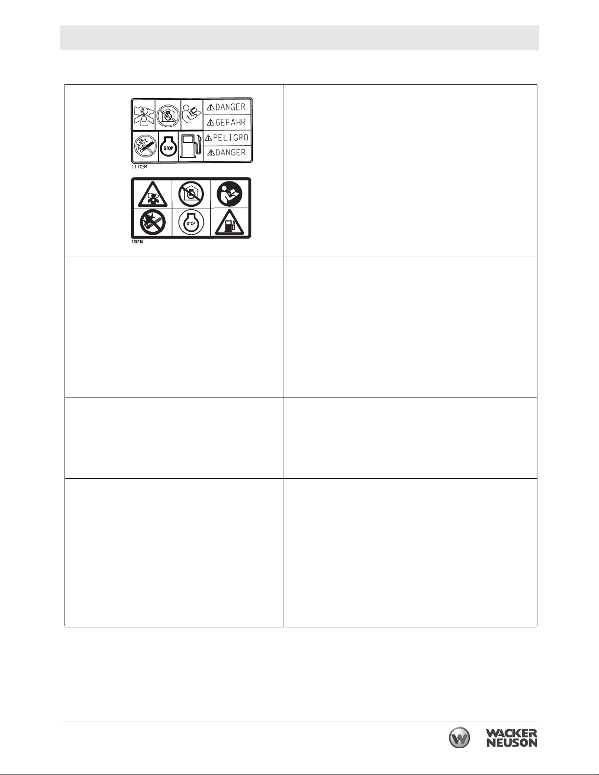
A DANGER
Asphyxiation hazard
Engines emit carbon monoxide.
Do not run the machine indoors or in an enclosed
area unless adequate ventilation, through such items
as exhaust fans or hoses, is provided.
Read the Operator’s Manual. No sparks, flames, or
burning objects near the machine. Stop the engine
before refueling.
B WARNING
Hot surface
C WARNING
Hand injury if caught in moving belt.
Always replace beltguard.
D WARNING
Always wear hearing and eye protection when operating
this machine.
wc_si000742gb.fm 17
Page 18
Labels CT 24-4A
178709
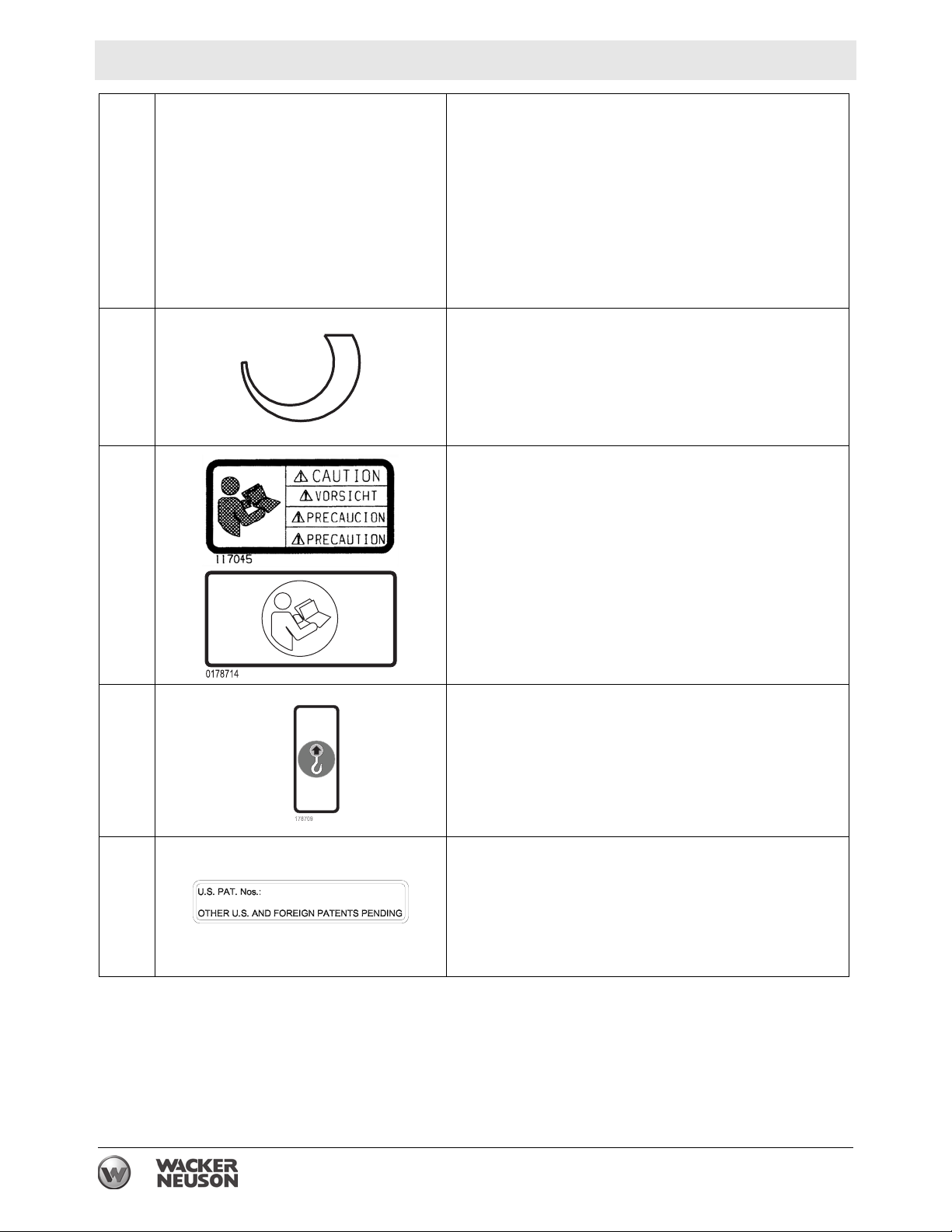
E WARNING
Cutting hazard. Always replace blade guard.
F Variable speed throttle
G CAUTION
Read and understand the supplied Operator’s Manual
before operating this machine. Failure to do so
increases the risk of injury to yourself and others.
H NOTICE
Lifting point
— This machine may be covered by one or more patents.
18 wc_si000742gb.fm
Page 19

CT 24-4A Labels
3
2
1
7
6
5
4
3
2
1
172847
J
111
172847
To start the machine:
1. Open the fuel flow valve.
2. Close the choke .
3. Push or turn engine switch to ON position.
4. Place throttle in the IDLE position.
5. Engage operator present lever.
6. Pull the rewind s tarter.
7. Open the choke.
To stop the machine:
1. Release operator present lever.
2. Push or turn engine switch to OFF position.
3. Close the fuel flow valve.
2
3
4
5
6
7
1
2
3
wc_si000742gb.fm 19
Page 20
Lifting and Transporting CT 24-4A
3 Lifting and Transporting
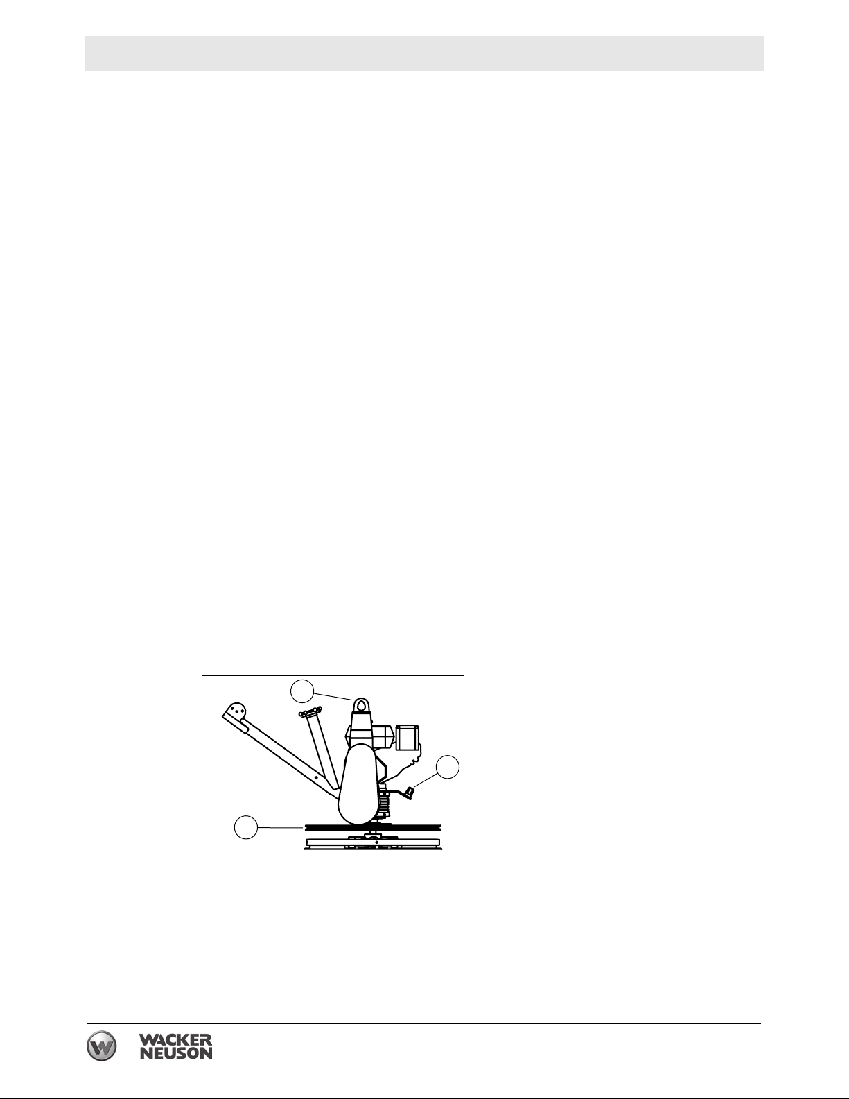
3.1 Lifting the Machine
NEVER lift the machine solely by the handle. The component may fail, causing the
machine to fall, possibly injuring bystanders.
WARNING
See Technical Data for the weight of the machine.
To lift the machine manually:
1. Stop machine.
2. Obtain a partner and plan the lift.
3. Balance the weight between the partners and lift the machine by the guard ring
(a).
To reduce risk of back injury while lifting, keep your feet flat on ground and shoulder
width apart. Keep your head up and back straight.
WARNING
To lift the machine mechanically:
WARNING
4. Stop machine.
5. See Dimensions and Weight for weight of machine and be sure that lifting
device(s) can safely lift the weight.
6. Attach hook, harness, or cable to the lifting bracket (b) on machine as shown
and lift as desired.
Do not lift the trowel overhead with a float pan attached, as the pan could fall off
and strike personnel working in the vicinity.
b
c
a
wc_gr004390
20
wc_tx003231gb.fm
Page 21

CT 24-4A Lifting and Transporting
3.2 Transporting the Machine
Requirements
Procedure
Transport vehicle capable of handling the weight of the trowel
Suitable ropes or chains
Follow the procedure below to tie down and transport the machine.
1. Lift the trowel onto the transport vehicle.
2. Position the handle so that it does not protrude outside the footprint of the
transport vehicle.
3. Connect the ropes/chains to the ring guard of the trowel as follows.
a.Connect them as low on the ring guard as possible to minimize stress on the
gearbox output shaft.
b.Use a crossing pattern as shown.
Result
4. Connect the ropes/chains to the transport vehicle. Do not overtighten them.
The machine is now ready to be transported.
wc_tx003231gb.fm
21
Page 22

Operation CT 24-4A
4 Operation
4.1 Preparing the Machine for First Use
1. Make sure all loose packaging materials have been removed from the machine.
2. Check the machine and its components for damage. If there is visible damage,
do not operate the machine! Contact your Wacker Neuson dealer immediately
for assistance.
3. Take inventory of all items included with the machine and verify that all loose
components and fasteners are accounted for.
4. Attach component parts not already attached.
5. Add fluids as needed and app licable , including fu el, en gine oil, and battery acid.
6. Move the machine to its operating location.
4.2 New Machine Set-Up
Trowels are shipped from the factory with the handle folded. Follow instructions on
Installing Blades and Unfolding Handle when setting up new machines or when
installing new blades.
22
wc_tx003232gb.fm
Page 23

CT 24-4A Operation
4.3 Recommended Fuel
The engine requires regular grade unleaded gasoline. Use only fresh, clean
gasoline. Gasoline containing water or dirt will damage the fuel system. Consult the
engine owner’s manual for complete fuel specifications.
Use of
oxygenated
fuels
Some conventional gasolines are blended with alcohol. These gasolines are
collectively referred to as oxygenated fuels. If you use an oxygenated fuel, be sure
it is unleaded and meets the minimum octane rating requirement.
Before using an oxygenated fuel, confirm the fuel's contents. Some states and
provinces require this information to be posted on the fuel pump.
The following is the Wacker Neuson approved percentage of oxygenates:
ETHANOL - (ethyl or grain alcohol) 10% by volume. You may use gasoline
containing up to 10% ethanol by volume (commonly referred to as E10). Gasoline
containing more than 10% ethanol (such as E15, E20, or E85) may not be used
because it could damage the engine.
If you notice any undesirable operating symptoms, try another service station, or
switch to another brand of gasoline.
Fuel system damage or performance problems resulting from the use of an
oxygenated fuel containing more than the percentages of oxygenates mentioned
above are not covered under warranty.
wc_tx003232gb.fm
23
Page 24

Operation CT 24-4A
4.4 Refueling the Machine
Requirements
Procedure
Machine shut down
Engine cool
Machine/fuel tank level with the ground
Fresh, clean fuel supply
Perform the procedure below to refuel the machine.
WARNING
Fire hazard. Fuel and its vapors are extremely flammable. Burning fuel can cause
severe burns.
f Keep all sources of ignition away from the machine while refueling.
f Do not refuel if the machine is positioned in a truck fitted with a plastic bed liner.
Static electricity can ignite the fuel or fuel vapors.
f Refuel only when the machine is outdoors.
f Clean up spilled fuel immediately.
1. Remove the fuel cap (a).
a
Result
b
wc_gr008400
2. Fill the fuel tank to the bottom of the fuel tank neck (b).
CAUTION
Fire and health hazard. Fuel expands when heated. Expanding fuel in an ove r-filled
tank can lead to spills and leaks.
f Do not overfill the fuel tank.
3. Reinstall the fuel cap.
The procedure to refuel the machine is now complete.
wc_gr008401
24
wc_tx003232gb.fm
Page 25

CT 24-4A Operation
4.5 Installing Blades
There are two types of blades available for the trowels. Float pans are large “pizza
pan” style blades, which hook on over finish blades. Float blades are used in the
earliest stages of work, and are not pitched.
Finish blades are used in the final stages of working, and are pro gressively pitched
to burnish the concrete.
Note: Trowel blades must NOT be interchanged, i.e., do NOT put larger diameter
blades on a smaller diameter trowel.
1. Secure blades to trowel arms with screws (b). Dip threads of screws in grease
prior to installation. This will prevent concrete from cementing the screws in
place and will make removal of the blades easier later on.
2. Plug the remaining threaded holes in the blade brace with plastic plugs (c) to
prevent them from filling with concrete.
Do not lift the trowel overhead with a float pan attached, as the pan could fall off
and strike personnel working in the vicinity.
WARNING
b
c
wc_gr004417
wc_tx003232gb.fm
25
Page 26

Operation CT 24-4A
4.6 Unfolding Handle
On new machines the pipe handle comes folded with the following components
attached: Twist pitch control (a), Operator Present Lever (b), throttle lever (c),
hinge pin (d), and adjustable lever (e).
To unfold and secure the pipe handle assembly:
1. While holding the hinge pin, unscrew and remove the adjustable lever and met al
washer.
2. Remove the hinge pin.
3. Straighten the pipe handle and re-insert the hinge pin.
4. Replace the met al wash er over the threa ded e nd of the h inge pin , and re-install
the adjustable lever.
5. Tighten the adjustable lever to lock the pipe handle in its fully opened position.
c
b
d
a
e
wc_gr004384
26
wc_tx003232gb.fm
Page 27

CT 24-4A Operation
4.7 Controls
Ref. Description Ref. Description
a Twist pitch control d Hinge pin
b Operator Present Lever e Adjustable lever
c Throttle lever — —
c
b
d
a
4.8 Operator Present Lever
When the Operator Present Lever (b) is released, the engine will shut off.
Watch for spinning blad es! Even after th e engine has shut of f, the trowel blades will
continue to rotate. To avoid severe injury, keep feet and fingers away from the ring
guard until the blades have come to a complete stop.
WARNING
e
wc_gr004384
wc_tx003232gb.fm
27
Page 28

Operation CT 24-4A
4.9 Before Starting
Before starting trowel, check the following:
oil level in engine
oil level in gearbox
fuel level
condition of air filter
condition of fuel lines
condition of trowel arms and blades
condition of ring guard
label descriptions
adjustable lever is tight
4.10 Starting
1. Open fuel valve by moving lever to the right (g1).
Note: If engine is cold, move choke lever to closed position (i1). If en gine is hot, set
choke to open position (i2).
2. Turn engine switch to “ON” (h1).
WARNING
WARNING
3. Move the throttle lever to the idle position (c1).
Start engine with throttle in the IDLE position. If the engine is started when the
throttle is not in the IDLE position, the trowel blades may spin unexpectedly and
cause injury.
4. Squeeze and hold the Operator Present Lever (b).
5. Pull starter rope (j).
Do not place foot on the ring guard when starting the engine, as severe injury can
occur if foot slips through the ring guard as the blades start to spin.
Note: If the engine oil is low, the engine will not start. If engine does not start,
check the oil level and add oil as needed.
6. Open choke as engine warms (i2).
7. Open throttle (c2) to operate trowel. Adjust blade RPM with throttle sp eed to suit
conditions.
28
wc_tx003232gb.fm
Page 29

CT 24-4A Operation
c
b
d
a
g1
g2
4.11 Stopping
1. Reduce engine RPM to idle by moving the throttle lever to idle position (c1).
2. Release the Operator Present Lever (b).
3. Turn engine switch to “OFF” (h2).
h2
h1
e
wc_gr004384
i2
i1
j
wc_gr001098
wc_tx003232gb.fm
4. Close fuel valve by moving lever to the left (g2).
29
Page 30

Operation CT 24-4A
4.12 Position of the Operator
Safe and efficient use of this machine is the operator’s responsibility. Full control of
the machine is not possible unless the operator maintains the proper working
position at all times.
While operating this machine the operator must:
stand or walk behind the machine, facing forward;
have both hands on the control handle;
and guide the motion of the trowel by applying do wnward pressure to the control
handle
4.13 Operation
Test the function of the Operator Present Lever before operating the trowel. Do not
operate the trowel if the Operator Present Lever is not functioning properly.
WARNING
Choose correct blade type and attach blades to trowel arms.
Note: When operating on sof t concrete, do not let trowel stand in one spot too long.
Always lift trowel from slab when operation is complete.
WARNING
WARNING
Note: “Left” and “Right” references are made from the operator's position.
1. Start engine and engage blades by increasing engine speed. Set speed with
throttle control on handle bar to appropriate speed for job conditions.
2. To move trowel forward twist handle clockwise (a).
3. To move backward twist handle counterclockwise (b).
4. To move to the left lift up slightly on the handle (c).
5. To move to the right press down slightly on the handle (d).
6. Clean trowel after each use to remove concrete splatter.
Allow the muffler to cool before cleaning or servicing the machine. A hot muffler
could ignite the fuel and start a fire.
Personnel other than the trowel operator should not be allowed in the work area, as
severe injury can occur from contact with operating trowel blades.
Do not attempt to clean, service or perform adjustments on the trowel while it is
running.
30
wc_tx003232gb.fm
Page 31

CT 24-4A Operation
a
c
b
wc_gr004418
4.14 Emergency Shutdown Procedure
Procedure
If a breakdown or accident occurs while the machine is operating, follow the
procedure below:
1. Stop the engine.
2. Close the fuel valve.
3. Remove the machine from the job site using correct lifting techniques.
4. Clean concrete from the blades and the machine.
d
wc_tx003232gb.fm
5. Contact the rental yard or machine owner for further instructions.
31
Page 32

Operation CT 24-4A
4.15 Pitch Adjustment
To adjust blade pitch (angle):
A = Twist pitch: turn the pitch adjusting knob (a) clockwise to increase pitch and
counterclockwise to decrease pitch.
Ref. B = Working condition of concrete C = Suggested working pitch
1 Wet surface working stage Flat (no pitch)
2 Wet to plastic working st age Slight pitch (5°)
3 Plastic working stage Additional pitch (10°)
4 Semi-hard working stage to
hard finishing stage (burnishing)
Maximum pitch (15°)
32
wc_tx003232gb.fm
Page 33

CT 24-4A Maintenance
5 Maintenance
5.1 Maintaining the Emission Control System
Normal maintenance, replacement or repair of emission control devices and
systems may be performed by any repair establishment or individual; however,
warranty repairs must be performed by a dealer/service center authorized by the
engine manufacturer. See the supplied engine owner’s manual for the applicable
emission warranty information.
5.2 Periodic Maintenance Schedule
The table below lists basic machine and engine maintenance. Tasks designated
with check marks may be performed by the operator . Tasks designated with square
bullet points require special training and equipment.
Refer to the engine owner’s manual for additional information.
Check fuel level.
Check engine oil level.
Inspect fuel lines.
Inspect air filter. Replace as needed.
Check external hardware.
Clean trowel after each use to
remove concrete splatter.
Grease blade arms as needed.
Clean air cleaner elements.
Change engine oil.
Check drive belt.
Clean sediment cup.
Daily
3
3
3
3
3
After
first
20 hrs.
Every
50
hrs.
Every
100
hrs.
Every
300
hrs.
wc_tx003233gb.fm
Check and clean spark plug.
Check and adjust valve clearances.
33
Page 34

Maintenance CT 24-4A
5.3 Engine Oil
1. Drain oil while the engine is still warm.
2. Remove the oil fill plug (a) and drain cap (b) to drain oil.
Note: In the interests of environmental protection, place a plastic sheet and a
container under the machine to collect any liquid which drains off. Dispose of this
liquid in accordance with environmental protection legislation.
3. Install drain cap.
4. Fill the engine crankcase with recommended oil up to the level of the plug
opening (c). See Technical Data for oil quantity and type.
5. Install the oil filler plug.
a
c
b
wc_gr00413
WARNING
Most used oil contains small amount s of materials that ca n cause can cer and other
health problems if inhaled, ingested, or left in contact with skin for prolonged
periods of time.
f Take steps to avoid inhaling or ingesting used engine oil.
f Wash skin thoroughly after exposure to used engine oil.
34
wc_tx003233gb.fm
Page 35

CT 24-4A Maintenance
5.4 Servicing the Air Cleaner
The engine is equipped with a dual element air cleaner. Service air cleaner
frequently to prevent carburetor malfunction.
NOTICE: Do not run engine without air cleaner. Severe engine dama ge will occur.
Never use gasoline or other types of low flash point solvents for cleaning the air
cleaner. A fire or explosion could result.
WARNING
To service:
1. Remove air cleaner cover (a). Remove both elements and inspect them for
holes or tears. Replace damaged elements.
2. Wash foam element (b) in solution of mild detergent and warm water. Rinse
thoroughly in clean water. Allow element to dry thoroughly. Soak element in
clean engine oil and squeeze out excess oil.
3. Tap paper element (c) lightly to remove excess dirt. Replace paper element if it
appears heavily soiled.
a
c
b
wc_gr000025
wc_tx003233gb.fm
35
Page 36

Maintenance CT 24-4A
5.5 Spark Plug
Clean or replace the spark plug as needed to ensure proper operation. Refer to
your engine operator’s manual.
The muffler becomes very hot during operation and remains hot for a while after
stopping the engine. Do not touch the muffler while it is hot.
WARNING
Note: Refer to section “Technical Data” for the recommended spark plug type and
the electrode gap setting.
1. Remove the spark plug and inspect it.
2. Replace the spark plug if the insulator is cracked or chipped.
3. Clean the spark plug electrodes with a wire brush.
4. Set the electrode gap (a).
5. Tighten the spark plug securely.
NOTICE: A loose spark plug can be come very ho t and may cause engine damage .
wc_gr000028
36
wc_tx003233gb.fm
Page 37

CT 24-4A Maintenance
5.6 Cleaning the Sediment Cup
1. Turn the fuel valve off.
2. Remove the sediment cup (a) and the O-ring (b).
3. Wash both thoroughly in a nonflammable solvent. Dry and reinstall them.
4. Turn the fuel valve on and check for leaks.
b
a
wc_gr000025
wc_tx003233gb.fm
37
Page 38

Maintenance CT 24-4A
5.7 Adjusting the Idle Speed
Remove the drive belt before making any adjustment to the carburetor. See Belt
Replacement. The blades will engage unless the belt is removed from the
machine.
WARNING
Adjust engine to the no load or idle speed per the Technical Data.
1. Start the engine and allow it to warm up to normal operating temperature.
2. Turn the throttle stop screw (a) in to increase speed, out to decrease speed.
Make sure the throttle lever is touching the stop screw before measuring rpm.
a
wc_gr001122
38
wc_tx003233gb.fm
Page 39

CT 24-4A Maintenance
5.8 Carburetor Adjustment
Remove the drive belt before making any adjustment to the carburetor. See Belt
Replacement. The blades will engage unless the belt is removed from the
machine.
WARNING
The pilot screw (a) is fitted with a limiter cap to prevent excessive enrichment of the
air-fuel mixture in order to comply with emission regulations. The mixture is set at
the factory and no adjustment should be necessary. Do not attempt to remove the
limiter cap. The limiter cap cannot be removed without breaking the pilot screw.
a
wc_gr001061
wc_tx003233gb.fm
39
Page 40

Maintenance CT 24-4A
5.9 Belt Replacement
The trowel is equipped with a self-adjusting clutch. This clutch automatically
tightens the belt and compensates for belt wear. Replace the belt if the clutch can
no longer tighten belt enough to engage gearbox without slipping.
To replace the drive belt:
1. Disconnect the spark plug lead.
To avoid accidental starting of the engine, always disconnect the spark plug lead
before working on machine.
WARNING
2. Loosen the screws (d) and remove the belt guard (c).
3. Slowly turn the pulley (b) and roll the belt (a) off.
Note: The clutch and the pulley are aligned at the factory and neither should be
removed during belt replacement.
4. Install the new belt.
5. Re-install the belt guard with washers and screws. Torque the screws to 5 Nm
(3.7 ft.lbs.).
a
c
b
d
wc_gr004429
40
wc_tx003233gb.fm
Page 41

CT 24-4A Maintenance
5.10 Trowel Lubrication
Grease trowel arms (b) with Shell Alvania RL2 grease or equivalent. Oil the pitch
control cable and other parts of trowel on an as needed basis.
Oil in the gearbox should not require replacement unless it was drained to service
gearbox. Check quantity through plug (a) located on side of gearbox. Oil level
should be to bottom of the plug threads. See Technical Data for oil quantity and
type.
a
b
wc_gr004389
wc_tx003233gb.fm
41
Page 42

Maintenance CT 24-4A
5.11 Storage
If trowel is being stored for more than 30 days:
Change engine oil.
Drain fuel from engine.
Remove spark plug and pour 15 ml (½ ounce) of SAE 30 engine oil into the
cylinder. Replace spark plug and crank engine to distribute oil. Refer to engine
manual.
Clean dirt from cylinder, cy linder head fins, blower housing, rot ating screen, and
muffler areas.
To save space, place handle in its storage position.
Cover trowel and engine and store in a clean, dry area.
42
wc_tx003233gb.fm
Page 43

CT 24-4A Troubleshooting
6 Troubleshooting
Problem / Symptom Reason / Remedy
Trowel does not develop full
speed.
Engine runs;
poor trowel operation.
Engine does not start or runs
erratically.
Trowel handle tends to rotate
when idling.
Remove deposits built up in engine cylinder and
engine head.
Engine speed too low. Adjust speed.
Clean or replace air filter.
Clean debris from moving parts and trowel blades.
In cold weather, warm engine in idle 3 or 4 minutes.
Check throttle lever and cable for proper operation.
Check drive belt for wear or damage.
Check clutch for wear or damage.
Clean debris from moving parts and trowel arms.
Check fuel level. Open fuel valve.
Clean air filter.
Check/replace spark plug.
Check in-line fuel filter.
Check engine oil level.
Check engine stop button.
Check that throttle is in idle position when starting
machine.
Check engine idle speed. (It may be too high).
Belt alignment may be off.
wc_tx003234gb.fm 43
Page 44

Technical Data CT 24-4A
C
E
D
A
B
7 Technical Data
7.1 Dimensions and Weights
Dimensions mm (in.) Dry Weight kg (lb)
A 1537 (60-1/2) without float pan 64 (141)
B 610 (24) with float pan 70 (153)
C 1003 (39-1/2) Full Wet (Operating) Weight kg (lb)
D 940 (37) without float pan 66 (145)
E 788 (31) with float pan 71 (157)
C
E
D
B
A
wc_gr004383
44
wc_td000545gb.fm
Page 45

CT 24-4A Technical Data
7.2 Engine
Engine Power Rating
Net power rating per SAE J1349. Actual power output may vary due to conditions
of specific use.
Item No.
Engine
Engine make Honda
Engine model GX 120 UT1 QX2
Max. rated power @ rated speed kW (Hp) 2.6 (3.5) @ 3600 rpm
Spark plug NGK BPR6ES / Denso
Electrode gap mm (in.) 0.7 – 0.8 (0.028 – 0.031)
Engine speed - operating rpm 3 80 0± 10 0
Engine speed - idle rpm 1 45 0± 10 0
Clutch engagement rpm 1800
Valve clearance (cold)
intake:
exhaust:
Air cleaner type Dual element
Engine lubrication oil grade SAE 10W30 API SJ or SL
mm (in.) 0.15 (0.006)
CT 24-4A
0620105, 0620849
W20EPR-U
0.20 (0.008)
wc_td000545gb.fm
Engine oil capacity L (oz.) 0.6 (20)
Fuel type Regular unleaded gasoline
Fuel tank capacity L (qt) 2.5 (2.64)
Running time hr 2
45
Page 46

Technical Data CT 24-4A
7.3 Trowel
Trowel
Model Item No.
CT 24-4A 0620105 610 (24) 4 Mobilgear
* Trowel blades must NOT be interchanged, i.e., do NOT put larger diameter blades on a
smaller diameter trowel.
Diameter*
mm (in.)
Number
of
Blades
Trowel
Gear Box
Lubrication
type/ml (oz.)
SH 220 Synthetic, ESeries
Approx.
620 (21)
Speed
Range
rpm
90–141 0–15
Pitch
Range
Degrees
46
wc_td000545gb.fm
Page 47

CT 24-4A Technical Data
7.4 Sound and Vibration Specifications
The required sound specification, Paragraph 1.7.4.2.4 of 2006/42/EC Machinery
Directive, is:
the sound pressure level at operator’s location (L
the guaranteed sound power level (L
) = 83 db(A)
WA
These sound values were determined according to ISO 3744 for the sound power
level (L
) and ISO 6081 for the sound pressure level (LpA) at the operator’s
WA
location.
ISO 5349 Part 1 Annex F states, “The vibration characteristics of a vibrating tool
can be highly variable. It is therefore important that the range of vibration
conditions associated with different workpieces, materials, working conditions,
methods of use of the tool, and exposure duration patterns be reported.”
The average hand and arm vibration value obtained for the entire operating rpm
range is 6.9 m/s².
The maximum hand and arm vibration value obtained within the entire operating
rpm range is 8.4 m/s².
The minimum hand and arm vibration value obtained within the entire operating
rpm range is 6.0 m/s².
) : 97 db(A)
pA
HA V
Uncertainties
The sound and vibration specifications were obtained on wetted and cured
concrete using the most commonly sold machine configurations. Vibration values
will vary depending on throttle position, operating conditions, and handle option.
Hand-transmitted vibration was measured per ISO 5349-1. This measurement
2
includes an uncertainty of 1.5 m/s
.
wc_td000545gb.fm
47
Page 48

Emission Control Systems Information and Warranty
8 Emission Control Systems Information and Warranty
The Emission Control Warranty and associated information is valid only for the
U.S.A., its territories, and Canada.
8.1 Emission Control Systems Warranty Statement
See the supplied engine owner’s manual for the applicable exhaust and
evaporative emission warranty statement.
48 wc_tx001753gb.fm
Page 49

CONCRETE POWER TROWEL
Table of Contents
Acknowledgment ....................................................................2
Foreword .................................................................................3
Safety Alerts ............................................................................4
A Word to the User/Operator ................................................5
Follow a Safety Program........................................................6
Prepare for Safe Operation ..................................................10
Start Safely ............................................................................17
Operate Safely ......................................................................19
Shut Down Safely .................................................................21
Perform Maintenance Safely ...............................................22
Final Word to the User .........................................................35
Acknowledgment
We wish to thank the members of the Association of Equipment Manufacturers for their invaluable
contributions in preparing this Safety Manual.
NOTICE OF COPYRIGHT PROTECTION
Copyright 2017, by the Association of Equipment Manufacturers. All rights reserved. This work may not be reproduced or disseminated in whole or in part by any means
2
without the prior written permission of the Association of Equipment Manufacturers.
Copyright ©2003–2016 AEM (Association of Equipment Manufacturers)
Revised 06/17
Page 50

Foreword
This safety manual is intended to point out some of the
basic safety situations that may be encountered during
the normal operation and maintenance of your trowel
and to instruct you in safety practices for dealing with
these conditions. This manual is NOT a substitute for
the manufacturer’s operating manual(s).
Additional precautions may be necessary, or some
instructions may not apply, depending on equipment,
attachments and conditions at the job site or in the
service area. The manufacturer has no direct control
over equipment application, operation, inspection, or
maintenance. Therefore, it is YOUR responsibility to use
good safety practices in these areas.
The information provided in this manual supplements
the specic information about your trowel that is
contained in the manufacturer’s operating manual(s).
Other information that may affect the safe operation of
your machine may be contained in the following:
• Safety signs
• Insurance requirements
• Employer safety and training programs
• Safety codes
• Local, state/pr
and r
egulations
ovincial, and federal laws, rules,
Read and understand
manuals before
operating
IMPORTANT! Before you operate this machine, make
sure you have the manufacturer’s manual(s) for this
trowel and all attachments. If the manufacturer’s
manual(s) are missing, obtain replacements from
your employer, equipment dealer, or directly from
the manufacturer. Keep this safety manual and the
manufacturer’s manual(s) with the machine at all times.
Read and understand all manuals.
Safety videos and other training resources are available
from some manufacturers and dealers. Operators are
encouraged to periodically review these resources.
3
Safety Alerts
Safety Alert Symbol
This Safety Alert Symbol means:
“Attention! Stay alert! Your safety is involved!”
The Safety Alert Symbol identies important safety
messages on equipment, safety signs, in manuals, or
elsewhere. When you see this symbol, be alert to the
possibility of death or personal injury. Carefully read the
message that follows and inform other operators. Follow
instructions in the safety message.
4
Signal Words
Signal words are distinctive words that are typically
found on safety signs on the concrete power trowels
and other job site equipment. These words may also be
found in this manual and the manufacturer’s manual(s).
These words are intended to alert the operator to a
hazard and the degree of severity of the hazard.
DANGER
WARNING
CAUTION
NOTICE
DANGER indicates a hazardous
situation that, if not avoided, will
result in death or serious injury.
WARNING indicates a hazardous
situation that, if not avoided, could
result in death or serious injury.
CAUTION indicates a hazardous
situation that, if not avoided, may
result in minor or moderate injury.
NOTICE is used to address
practices not related to physical
injury.
Page 51

A Word to the User/Operator
It is YOUR responsibility to read and understand this
safety manual and the manufacturer’s manual(s) before
operating this equipment. This safety manual takes you
step by step through the working day.
Graphics have been provided to help you understand
the text.
Hazard recognition and accident prevention depend
upon you being alert, careful, and properly trained in the
inspection, operation, transport, maintenance, and
storage of this equipment.
Read and
understand all
safety signs –
replace damaged
signs
Remember that YOU are the key to safety. Good
safety practices not only protect you but also protect
the people around you. Study this manual and the
manufacturer’s operating manual(s) for the specic
machine. Make them a working part of your safety
program. Keep in mind that this safety manual is written
only for concrete power trowels.
After studying the manufacturer’s operating manual(s)
and this safety manual, please contact the equipment
manufacturer with any remaining questions.
Practice all usual and customary safe working
precautions and remember:
Safe operation is up to you!
You can prevent death or serious injury caused by
unsafe work practices!
5
Follow a Safety Program
For Safe Operation
You must be a qualied and authorized operator for safe
operation of this trowel. You must clearly understand
the written instructions supplied by the manufacturer,
be trained—including actual operation—and know the
safety rules and regulations for the job site. It is a good
safety practice to point out and explain safety signs and
practices to others, and to make sure they understand
the importance of following these instructions.
Never operate while
impaired by alcohol
or drugs
WARNING! Death or serious injury could result from
operating machinery while impaired by drugs or alcohol.
Drugs and alcohol affect operator alertness,
coordination, and the ability to safely operate the
equipment. Never operate the trowel while impaired
by use of alcohol or drugs. Never knowingly allow
anyone to operate the machine when their alertness
or coordination is impaired.
6
An operator taking prescriptions or over-the-counter
medication must consult a medical professional
regarding any side effects of the medication that would
hinder their ability to safely operate this equipment.
Be Alert!
Know where to get assistance. Keep emergency
numbers for doctors, ambulance service, hospital, and
re department near your telephone. Know how to use a
rst aid kit and re extinguisher/re suppression system;
know their location and practice getting to them. Ensure
they have been properly tested and maintained.
Let others know where you will be working, and what
time you will be returning. In case of an emergency, you
want others to know where to nd you.
Be Aware!
Take advantage of training programs offered.
Know the proper response to a re or chemical spill on
your trowel.
Page 52

Follow a Safety Program
Be Careful!
Human error is the result of many factors: carelessness,
fatigue, sensory overload, preoccupation, unfamiliarity
with the machine or attachments, or drugs and alcohol,
to name a few. You can avoid death or serious injury
caused by these and other unsafe work practices. Be
careful; never assume accidents cannot happen to you.
For your safety and the safety of others, act safely and
encourage your fellow workers to act safely as well.
Protect Yourself
Wear all the personal protective clothing and Personal
Protective Equipment (PPE) issued to you or called for
by job conditions.
You may need:
• Hard hat
• Safety shoes
• Safety glasses, goggles, or face shield
• Heavy duty gloves
• Hearing protection
• Reective clothing
• Wet weather gear
• Respirator or lter mask
Wear whatever is needed to protect yourself—don’t take
chances.
WARNING! Avoid death or serious injury from
entanglement. Do not wear loose or frayed clothing
or accessories that could catch on moving parts.
Examples of items to avoid include opping cuffs,
dangling neckties and scarves, wallets attached to
chains, jewelry and wrist watches.
7
Follow a Safety Program
Know the Rules
Most job sites have rules governing equipment use and
maintenance. Before you start work at a new location,
check with the supervisor or safety coordinator. Ask
about the rules you will be expected to obey.
OSHA enforces federal laws within the United States
that apply to the safe operation, application, and
maintenance of equipment on some job sites. It is the
employer’s responsibility to comply with these laws. A
federal representative may periodically inspect a job site
to see that these laws are being followed.
There may be other local, state/provincial, federal laws
or international organizations that regulate the use of
this equipment, along with specic job site or employer
rules. It is important that you know and comply with all
applicable laws and rules, including those requiring
operator training and certification.
These are some of the rules you must work by:
Only qualied and authorized individuals may operate
•
this equipment.
Inspect your machine and attachments befor
•
use as specied by the manufactur
employer.
8
er and your
e each
Know the operating characteristics of your
•
equipment. Do not misuse it.
• Wear proper clothing and PPE. Check that others ar
also wearing appropriate clothing.
• All shields, guar
doors must be pr
• Know the rules regarding traf
what all signs, ags, and markings mean. Know hand,
ag, horn, whistle, siren, or bell signals, if used.
• Never modify or r
(except for qualied service personnel; then make
sure the part is re-installed or replaced if defective or
worn out).
ds, air lters, access panels, and
operly installed before each use.
c at your job site. Know
emove any part of the machine
Safety Rules
•
•
•
•
•
•
•
•
•
•
Know and understand
rules of operation
Keep bystanders
away
e
Page 53

Follow a Safety Program
• Never allow children to play near, ride on or
operate the equipment.
• Keep bystanders away from the machine during
operation.
• Know the work area before you use the equipment.
Be aware of possible hazards.
• Only use attachments and parts that are approved by
the manufacturer.
• Follow all safe shutdown instructions (See page 21,
Shut Down Safely).
Know the Equipment
Read and understand the DANGER, WARNING,
CAUTION, and NOTICE safety labels and other
informational signs on the machine, the attachments,
and in the manufacturer’s operating manual(s). Ask your
supervisor or dealer to explain any information you do
not understand. Failure to obey safety instructions could
result in death or serious injury.
Know the following about your equipment:
• Function, purpose, and use of all controls
• Correct operation speeds
• How to quickly stop equipment in an emergency
• Rated operating capacity
• Know the meaning of all identication symbols on the
controls and gauges
• Know the location and type of emergency
shut-down control the trowel is equipped with
• Never start or operate the trowel without protective
guards and panels in place
• Know the capabilities and limitations of the trowel
Read and understand
manuals before
operating
Dust Precaution
Some dust created by construction activities may cause
silicosis or respiratory harm.
Your risk of exposure varies depending on how often
you do this type of work. To reduce your risk, work
in a well ventilated area, use a dust control system,
and wear approved personal safety equipment such
as a dust/particle respirator designed to lter out
microscopic particles.
9
Prepare for Safe Operation
Load and Unload Safely
Precautions
• Power trowels are heavy and awkward to move
around.
• Do not attempt to lift the ride-on trowel by the guard
rings.
• Use proper heavy lifting procedures.
• Keep all non-essential personnel clear of the area.
• Never lift the trowel over areas where people are
standing or working.
• Remove tools and loose items before lifting.
• Make sure the crossbars on the safety catches are in
good condition if so equipped.
• Always consult the machine’s operator’s manual for
the best and proper lifting, loading, and unloading
methods.
Read and understand
manuals before
loading and unloading
10
Walk-Behind Trowels
Some walk-behind trowels can be lifted or moved
by two people utilizing lifting tubes or other special
attachments. Generally however, they must be lifted
using lifting bales (special lifting brackets), or other
specic lifting points provided by the manufacturer, and
cranes, hoists, or forklifts. Be certain any lifting devices
used have adequate capacity.
Ride-On Trowels
Ride-on trowels are very heavy. They require heavy-duty
lifting devices such as cranes or heavy-duty hoists to lift
them on and off the concrete slab.
Be certain any lifting devices used have adequate
capacity. Some ride-on trowels are equipped with lifting
bosses that are used with specialized apparatus to
assist in moving the trowels around. Use extreme care
when lifting or moving a ride-on trowel.
Page 54

Prepare for Safe Operation
Check and Use All
Available Safety Devices
To protect you and others around you, your machine
may be equipped with the safety equipment listed
below. Additional equipment may be required or some
items may not apply, depending on attachments used,
job site conditions, or applicable job site rules. Check
that each required item is securely in place and in
operating condition:
• Emer
•
• Alarms or Warning Lamps
• Drain Covers, Plugs, and Caps
• Pressure Relief Devices
• Lights
• Special enclosures or accessories requir
•
Use them! Never remove or disconnect any safety
device.
gency stop switch or other “Shut-Down”
devices
Guards, Shields & Panels
ed for
specic applications or job site conditions
Safety Signs
Check the Machine
Before beginning your work day, inspect the machine
and have all systems in good operational condition.
• Perform daily and periodic service procedures as
instructed by the equipment manufactur
• Check for broken, missing, loose, or damaged parts.
Make necessary r
• Keep handholds clean and free of grease, oil, dirt,
snow or ice.
• Ensure shielding is properly installed and in good
condition. Repair or r
• Ensure all tools or loose objects are removed or
ely fastened before operating the machine.
secur
epairs.
Inspect
the machine before
each work day
eplace if damaged or missing.
er.
11
Prepare for Safe Operation
Hydraulic Fluid Injection Hazard
WARNING! Accidental injection of pressurized uid
into the hands or body is dangerous and could result in
death or serious injury. Use caution when checking
hydraulic leaks as pressurized hydraulic fluid has
enough force to penetrate skin, causing serious
personal injury.
If a leak is discovered:
• Ensure engine is turned off; relieve pressur
hydraulic cir
• Wear proper hand and eye protection.
Visually examine the hydraulic hose or uid lines in
•
the vicinity of the leak for br
use your hand to check for leaks.
•
Repair or replace hydraulic lines per manufacturer’
r
ecommendation.
Fluid injection injuries are not always obvious. Victims
have reported such injuries feel like a bee sting or
splinter under the skin. If you suspect you have a uid
injection injury, do not take chances. Seek proper
medical care immediately. If any uid is injected into the
skin, it must be surgically removed within a few hours by
a doctor familiar with this type of injury.
12
cuit.
eaks or cracks.
e in
Do not
Pressurized
fluid can inject
into the body
Wear proper
s
hand and eye
protection
Page 55

Prepare for Safe Operation
Check the Cooling System
When checking the cooling system, make sure the
engine is turned off and is cool. Remove the key to
prevent fans from unexpectedly starting. Ensure the
coolers and engine compartment are clean and free
from debris, which could ignite and cause a re.
If the machine is air-cooled, be sure the cooling unit
has an unobstructed air ow. If it is liquid-cooled, check
coolant level (at overow tank, if provided).
Allow radiator to cool
before removing cap
slowly
WARNING! Allow the radiator to cool before
checking the level. Hot radiator uids could escape as
steam and burn you. (See page 27, Engine Coolant
Hazards.)
Use Caution When Fueling
WARNING! Avoid injury from re or explosion.
Never fill the fuel tank with the engine running, while
smoking or when near an open flame.
Never overll the tank or spill fuel. If fuel is spilled, clean
it up immediately.
Be sure to use the correct type and grade of fuel.
Ground the fuel funnel or nozzle against the ller neck to
prevent sparks that could ignite fuel vapors. Be sure to
replace the fuel ll cap (if equipped) when you are done.
No smoking and
no open flames in
flammable/explosive
atmospheres
13
Prepare for Safe Operation
Ultra-Low Sulfur Diesel (ULSD)
Fuel Hazard
Avoid Static Electricity Risk When Fueling
WARNING! Ultra-Low Sulfur Diesel (ULSD) poses a
greater static ignition hazard than earlier diesel
formulations. Avoid death or serious injury from re or
explosion; consult with your fuel or fuel system
supplier to ensure the delivery system is in
compliance with fueling standards for proper
grounding and bonding practices.
Static discharge
during fueling can
cause explosion
Follow Safe Operating Practices
Exhaust Fumes in a Closed Space Can Kill
Vent exhaust and assure a ow of fresh air when an
internal combustion engine is used in a closed space.
14
WARNING! Exhaust fumes from diesel, gasoline or
LP gas engines can kill. Do not breath exhaust fumes
from any kind of engine.
Ventilate
work area
Operating in Flammable/Explosive Atmospheres
WARNING! A trowel must not be operated in
flammable or explosive atmospheres. Use in
explosive atmospheres can result in res and/or
explosions which could cause serious injury or death.
Do not operate in
explosive/flammable
atmosphere
Page 56

Prepare for Safe Operation
Avoid Crystalline Silica (quartz) Dust
WARNING! Avoid exposure to dust containing
crystalline silica particles. This dust can cause
serious injury to the lungs (silicosis).
Avoid silica dust
Because crystalline silica is a basic component of sand
and granite, many activities at construction sites
produce dust containing crystalline silica. Trenching,
sawing and boring of material containing crystalline
silica can produce dust containing crystalline silica.
If dust which contains crystalline silica is present there
are guidelines which should be followed.
1. Be aware of the health effects of crystalline silica and
that smoking adds to the damage.
2. Be aware of and follow OSHA (or other) guidelines for
exposure to airborne crystalline silica.
3. Know the work operations where exposure to
crystalline silica may occur.
4. Participate in air monitoring or training programs
offered by the employer.
5. Be aware of and use optional equipment controls such
as water sprays, local exhaust ventilation, and
enclosed cabs with positive pressure air conditioning.
6. Where respirators are required, wear a respirator
approved for protection against crystalline silicacontaining dust. Do not alter the respirator in any way.
Workers who use tight-fitting respirators cannot have
beards/mustaches which interfere with the respirator
seal to the face.
7. If possible, change into disposable or washable work
clothes at the worksite; shower and change into clean
clothing before leaving the worksite.
8. Do not eat, drink, use tobacco products, or apply
cosmetics in areas where there is dust containing
crystalline silica.
9. Store food, drink and personal belongings away from
the work area.
10. Wash hands and face before eating, drinking, smoking, or applying cosmetics after leaving the exposure
area.
15
Prepare for Safe Operation
Know the Working Area
Learn as much about your working area as possible.
Check at Ground or Floor Level
Thoroughly check the area for unusual or dangerous
conditions, such as tools, or items that may damage the
trowel or be propelled by the trowels rotating blades.
Note where pipes and forms are located. Locate and
mark protrusions (rebar, anchor bolts, oor drains, etc.)
in the concrete.
Plan Your Work
Know in advance the conditions likely to be
encountered, and plan for any likely emergency.
Getting on and off a Ride-On Trowel
If operating a ride-on trowel, mount and dismount
carefully. Use the steps and hand holds provided. Do
not use control levers as hand holds and never use
guard rings as steps. Watch for surfaces that may be
slippery. Never jump off a ride-on trowel.
16
Operating on an Elevated Deck
(Multi-Story Operation)
Consult local/state regulations before you operate
equipment on an elevated deck. If operating on an
elevated deck, ensure perimeter safety cabling of proper
size and strength is in place. Do not operate the trowel
close to the edge of the deck.
Use three points
of contact when
mounting and
dismounting
Page 57

Start Safely
Warn Personnel Before Starting
Before starting, walk completely around the machine.
Make sure no one is on it or close to it. Let others
know you are starting up and don’t start until everyone
is completely clear of the machine. As the equipment
operator, you are responsible for the safe use of the
machine, so always make sure you have communicated
your work plans to others on the site.
Before starting,
walk completely
around trowel
Check the trowel thoroughly at delivery for any shipping
damage.
Locate the trowel in an accessible location, as close to
the work site as possible.
Secure the trowel after it is placed in its intended
operating position so it does not tip, roll, slide or fall.
Starting the Engine
WARNING! Never attempt to start the engine by
shorting across starter terminals. Serious injury or
death may result.
Know the exact starting procedure for your machine.
See the manufacturer’s operating manual(s) for starting.
• Familiarize yourself with war
operating contr
• Make sure controls are in the neutral/locked position.
• Clear the area of all persons.
Start the engine following the instructions in the
•
manufacturer’s operating manual(s).
• If necessary to run the engine or operate the machine in
an enclosed ar
WARNING! Never operate the machine without
adequate ventilation. Exhaust fumes can kill. Do not
breathe exhaust fumes!
For a walk-behind (pedestrian operated) trowel machine,
make sure that a circular area with a minimum radius
equal to the length of the machine is clear. This will
ensure safety of personnel around the machine.
ols.
ea, ensure there is adequate ventilation.
ning devices, gauges and
17
Start Safely
Starting Aids
If you have trouble starting the engine and need to use
jumper cables, follow the instructions in manufacturer’s
operating manual(s). Jump-starting is a two-person
operation. The operator must be in the operator’s seat
when jump-starting so the machine will be under control
when the engine starts.
WARNING! Improper jump-starting procedures may
cause serious injury or death from a battery explosion or
a run-away machine. Always use proper jump-starting
procedure. (See page 29, Battery Hazards.)
To avoid explosion,
follow proper jump-
starting procedures
Never start engine
by shorting across
starter terminals
18
Ether/cold start uid is HIGHLY FLAMMABLE. Before
using it, always read the instructions on the ether/
cold start uid container and the instructions in the
manufacturer’s operating manual(s).
WARNING! Avoid injury from explosion or re. If the
engine is equipped with a glow plug pre-heater or other
intake manifold type pre-heater, follow manufacturer’s
instructions before using ether/cold start uid.
After Starting Engine
Observe gauges, instruments, and warning lights to
assure that they are functioning and their readings are
within the operating range.
Run an Operating Check
Do not use a machine that is not in proper operating
condition. It is your responsibility to check the condition
of all systems and to run the check in a safe area.
Page 58

Operate Safely
Walk-Behind Trowels
• Ensure that the operator is familiar with the trowel
and is trained on its operation.
Do not start or operate the trowel if the drive train will
•
not disengage. Centrifugal for
and surface when starting can cause uncontrolled
handle movement that can cause serious injury. The
handle must not move while pulling the engine recoil
starter
.
• Visually check to be sure that the blades are fr
obstructions and the ar
• For trowels that use this feature, ensur
emer
gency stop switch is in the ON position.
• Move the throttle to the idle position.
• Switch the engine ON/OFF switch to the ON position.
• Never place your foot on the ring guar
the engine or severe injury can occur if your foot slips
thr
ough the ring guard as the blades start to spin.
While rmly holding the handle with one hand, start
•
the engine following the guidelines in the engine
manufactur
Hold the handle bar rmly with both hands while the
•
tr
owel is “throttled-up”.
er’s instruction manual.
ce between the tr
ea is clear for operation.
e that the
d when starting
owel
ee of
• If control of the tr
attempt to r
moving. Depending on the engine speed, the trowel
handle can swing ar
owel is lost, stay clear and do not
egain control until the tr
ound before it stops completely.
owel has stopped
Ride-On Trowels
• Ensure that the operator is familiar with the trowel
and is trained on its operation.
Ensure the operator is well rested and not fatigued,
•
is alert, and not impaired in any way (medications,
drugs, alcohol, etc.).
•
Adjust the seating if necessary and get into
a comfortable position wher
accessible.
•
Visually check to be sure that the blades are fr
obstructions and the ar
• Start the tr
engine manufactur
power
and cold start operation.
•
Observe any gauges and warning lights to ensur
they ar
manufactur
• Check operation of contr
operate pr
owel following the instructions in the
er’
owels, follow the instructions for glow plug
ed tr
e functioning and their readings ar
er’s normal operating range.
operly.
e all controls ar
ea is clear for operation.
s operation manual. For diesel
ols. Make certain they
e
ee of
e within the
e
19
Operate Safely
Electrical Equipment
Some walk-behind trowels are powered by electric
motors. Electric motors and components present
special hazards during operation. Read the operator’s
manual.
• Never operate a trowel with a damaged or wor
electrical cor
sure to use one heavy enough to carry the current
load. When trowel is used outdoors, use only
extension cords that are marked for outdoor use.
• Use only appr
extension cor
grounding-type plugs and
receptacles that accept the
machine’s plug.
• Use an electrically power
tr
owel that has been built
in accordance with the
requirements of the National
Electrical Code (NFPA-70)
and has been approved by a
Nationally Recognized Test
Lab.
20
d. When using an extension cord, be
opriate
ds that have
ed
• Keep all electrical cords away from r
components, heat, oil, and sharp edges to avoid
damaging them.
•
n
Avoid body contact with gr
pipes, metal railings, radiators and metal ductwork.
Always check the power supply befor
•
owel. Using the wr
tr
the motor
• Always make sur
stop position befor
power supply
• Do not operate an electric powered tr
rain or snow
cor
• Never operate the trowel in ar
ammable or explosive liquids or gases. Sparks
could ignite fumes.
.
e the motor switch is OFF or in the
e plugging the tr
.
. Keep the motor
ds dry.
ounded surfaces such as
ong voltage supply will damage
otating
e running the
owel into the
owel in the
, switch, and electrical
eas exposed to
Page 59

Shut Down Safely
Storage
Always store equipment properly when it is not being
used. Equipment should be stored in a clean, dry
location out of reach of children.
WARNING! Avoid death or serious injury. Never
leave a machine unattended with the engine running.
Safe Shutdown
The detailed shutdown procedure is given in your
manufacturer’s manual(s). In general, this includes:
• Stop machine.
• Position controls in neutral or locked position.
• Idle engine for short cool-down period.
• Stop engine and remove ignition key (if equipped).
• Cycle hydraulic controls to eliminate pressure.
• Lock covers and enclosures.
• Shut off master electric switch (if equipped).
Perform Maintenance Safely
Shut engine off,
remove key
21
Know What You’re Doing
Maintenance on this type of machine is not for
inexperienced or untrained personnel. It can be
hazardous unless performed properly. Be sure you
have the necessary skill, information, correct tools, and
proper equipment to do the job safely.
Be sure to maintain the equipment according to the
manufacturer’s instructions. Regularly check the
operation of the protective and safety devices.
Do not perform any work on a machine unless you are
authorized and qualied to do so.
If you have been authorized to perform maintenance,
read the manufacturer’s operating and service
manual(s). Study the instructions: check the lubrication
charts, examine all the instruction messages on the
machine.
Maintain equipment
22
Protect Yourself
Wear all the personal protective clothing and PPE
issued to you or called for by job conditions.
You may need:
• Hard hat
• Safety shoes
• Safety glasses, goggles or face shield
• Heavy duty gloves
• Hearing protection
• Reective clothing
• Wet weather gear
• Respirator or lter mask
Wear whatever is needed to protect yourself. Do not
take chances.
Page 60

Perform Maintenance Safely
WARNING! Avoid death or serious injury from
entanglement. Do not wear loose clothing or
accessories. Stay away from all rotating components
when the engine is running. Contact, wrapping or
entanglement with rotating or moving parts could result in
death or serious injury.
Wear a rubber apron and rubber gloves when working
with corrosives. Wear gloves and safety shoes when
handling wooden blocks or sharp-edged metal.
Always use safety glasses, goggles or a face shield.
They provide eye protection from uids under pressure,
during grinding and while servicing batteries. Protection
is also needed from ying debris, liquids and loose
material produced by equipment, tools and pressurized
air/water.
Wear a face shield and follow manufacturer’s instructions
when you disassemble spring-loaded components or work
with battery acids. Keep pockets free of all objects that
could fall out and drop into machinery.
Handle tools and heavy parts sensibly, with regard for
the safety of yourself and others. Lower items; don’t
drop them.
Avoid rotating parts
Wear eye protection
Do not
loosen
radiator cap
until cool
23
23
Perform Maintenance Safely
Prepare the Work Area
• Position the machine in a level area out of the way of
other working equipment.
• Make sure there is adequate light, ventilation and
clearance.
• Remove oil, grease or water to eliminate any slippery
surfaces.
• Clean around the area to be serviced to minimize
contamination.
Avoid falls, clean
slippery surfaces
Prepare the Machine
Stored energy sources (electrical, mechanical, hydraulic,
pneumatic, chemical, thermal, etc.) must be controlled
or reduced to a practical minimum before performing
any maintenance, repair, or service procedures.
CAUTION! Load and unload machinery using proper
procedures. (See page 10, Load and Unload Safely.)
24
Safety practices to prevent potential injuries from
energy-releasing sources include:
• Place controls in NEUTRAL or LOCKED position
before shutting off engine.
• Allow all moving parts to stop.
• Shut off engine.
• Follow your manufacturer’s recommendation for
relieving hydraulic system pressure.
• Lock ignition, remove key (if equipped) and take it
with you.
• Look and listen for evidence of moving parts before
dismounting.
• Shut off master electrical switch (if equipped).
• Securely support or block up machine before working
underneath machine or other lifted components.
• Securely support, block up, or lock up other
components with approved locking devices before
working near or underneath them.
• Relieve pressure before disconnecting or
disassembling any pressurized system.
• Block or relieve spring pressure before disassembling
any spring-loaded mechanism.
• Avoid ames, sparks, or smoking near any fuel,
hydraulic uid or other ammable material such as
spraying debris.
Page 61
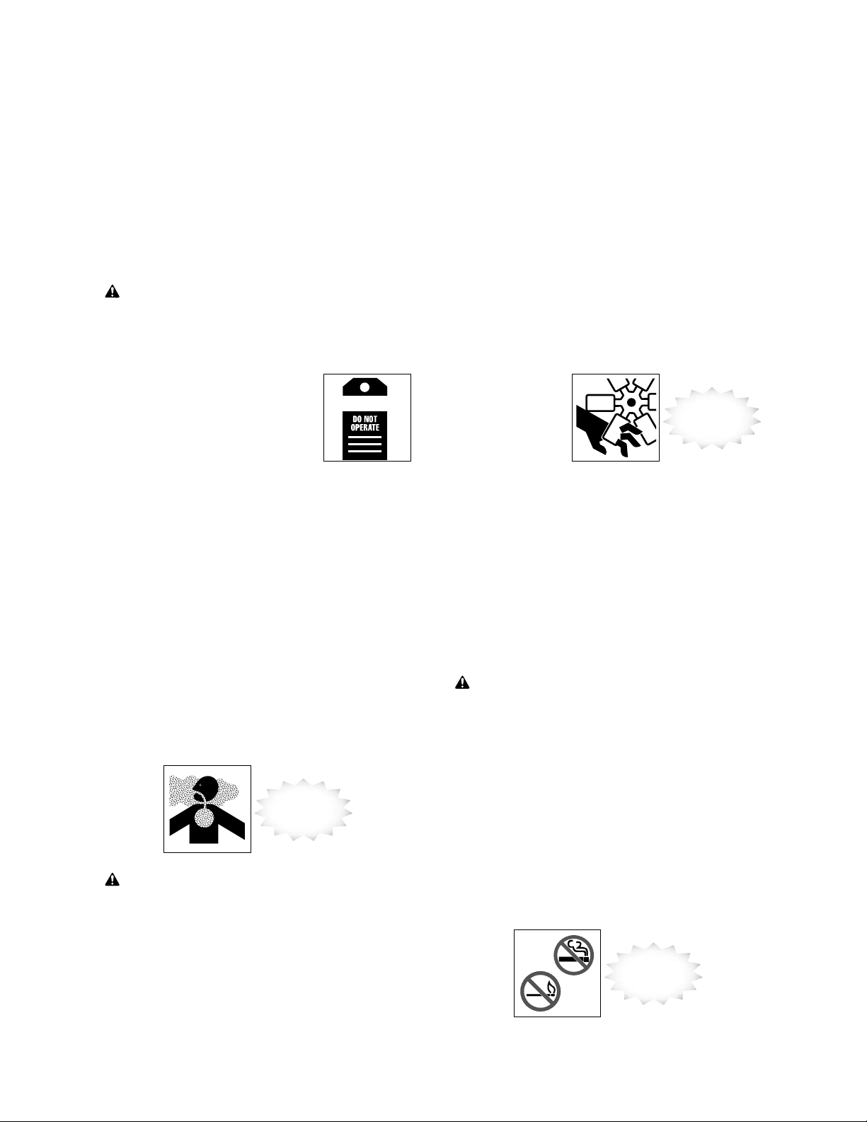
Perform Maintenance Safely
Attach a “DO NOT OPERATE” warning tag to the
control levers. Lockout/tagout the unit according to the
manufacturer’s operating manual(s). If there is a key,
remove it and take it with you.
Install approved support device(s) when working under
or near raised equipment.
Remove only guards or covers that provide access to
the area being serviced. Replace all guards and covers
when work is complete.
Do not operate the machine with gaurds removed.
WARNING! Avoid injury or death. Never work on
machinery with the engine running unless instructed
by the manufacturer’s manual(s) for specific service.
Trowel Maintenance and Repair
MAKE SURE the trowel is
disconnected from the power source
or the appropriate circuits are dead
and OSHA Lockout/Tagout is applied
before doing any maintenance or
repair work on the trowel.
WARNING
Trowel Blades, Pans and Attachments
• Do not attempt to clean, service or perform
adjustments on the tr
• Do not remove blades or pans while the tr
is hanging overhead. Always support the trowel
ely on a at, level surface befor
secur
blades or pans.
•
Always handle blades and pans carefully. Worn
blades or pans may develop sharp edges that can
cause serious cuts.
•
Always replace wor
parts designated by the manufactur
Replace blades and pans as a complete set – even
•
if only one blade or pan is showing wear or damage.
They can wear dif
and a dif
of the slab surface.
Only use
•
manufacturer
approved
polishing
and brush
attachments.
ence in blade size will damage the nish
fer
owel while it is running.
owel
e changing
n or damaged parts with service
er.
ferently depending on differ
Avoid
rotating parts
ent jobs,
25
25
Perform Maintenance Safely
Common Maintenance
Safety Practices
Use Proper Ventilation
Never run an engine in an enclosed area without an
approved ventilation system.
Ventilate work area
WARNING! Exhaust fumes contain carbon
monoxide which could be deadly if inhaled. Never
operate any type of engine without proper
ventilation. EXHAUST FUMES CAN KILL.
A feeling of tiredness, or nausea, is an indication of
being overcome by exhaust. Shut the engine off
immediately if this occurs.
26
Fuel Hazards
WARNING! Avoid serious injury or death. Always
use approved fuel containers and/or fuel dispensing
equipment to reduce the risk of explosion or fire.
Always observe these practices to reduce the possibility
of a serious accident:
• Shut off engine and ignition during refueling.
• Turn off all electrical switches.
• Ground the fuel nozzle against the ller neck.
• Keep sparks and open ames away fr
not smoke while refueling or when handling fuel
containers.
•
Do not cut or weld on or near fuel lines, tanks or
containers.
•
Do not overll the tank or spill fuel. Clean up spilled
fuel immediately. Clean spills immediately.
No smoking and no
open flames
om fuel. Do
Page 62

Perform Maintenance Safely
Ultra-Low Sulfur Diesel (ULSD) Hazard
WARNING! Ultra-Low Sulfur Diesel (ULSD) poses a
greater static ignition hazard than earlier diesel
formulations with higher sulfur content. Avoid death or
serious injury from re or explosion; consult with your
fuel or fuel system supplier to ensure the delivery
system is in compliance with fueling standards for
proper grounding and bonding practices.
Engine Coolant Hazards
WARNING! Avoid serious injury or death. Liquid
cooling systems build up pressure as the engine gets
hot, so use extreme caution before removing the
radiator cap.
• Stop the engine and wait for the system to cool.
• Wear protective clothing and safety glasses.
• Turn the radiator cap slowly to the rst stop to allow
the pressure to escape before removing completely.
Allow radiator to cool
before removing cap
slowly
Engine Coolant Hazards (cont.)
CAUTION! Before replacing engine coolant, refer to
the manufacturer’s operating manual(s) for direction.
Using incorrect coolant type may cause overheating and
increase safety risks.
Hydraulic System Hazards
Be sure to follow manufacturer’s instructions for relieving
uid pressure before performing any maintenance. The
hydraulic system is pressurized whenever the engine is
on and may hold pressure even after the engine is shut
off. Cycle hydraulic controls, including auxiliary hydraulic
control (if equipped), after the engine is shut off.
Check for
leaks and inspect
hoses
27
27
Perform Maintenance Safely
Hydraulic System Hazards (cont.)
During inspection of the hydraulic system:
• Wait for uid to cool before disconnecting the lines
Hot hydraulic uid can cause severe burns.
• Wear appropriate eye protection. Hydraulic uid can
cause permanent eye injury.
• When venting or lling the hydraulic system, loosen
the ller cap slowly and remove it gradually.
• Never reset any relief valve in the hydraulic system
to a pressure higher than recommended by the
manufacturer.
Hydraulic Fluid Injection Hazard
WARNING! Accidental injection of pressurized uid
into the hands or body is dangerous and could result in
death or serious injury. Use caution when checking
hydraulic leaks as pressurized hydraulic fluid has
enough force to penetrate skin, causing serious
personal injury.
If a leak is discovered:
• Ensure engine is turned off; relieve pressure in
hydraulic circuit.
• Wear proper hand and eye protection.
28
• Visually examine the hydraulic hoses or uid lines in
the vicinity of the leak for breaks or cracks. Do not
use your hand to check for leaks.
• Repair or replace hydraulic lines according to the
manufacturer’s recommendations.
Fluid injection injuries are not always obvious. Victims
have reported such injuries feel like a bee sting or
splinter under the skin. If you suspect you have a uid
injection injury, do not take chances. Seek proper
medical care immediately. If any uid is injected into the
skin, it must be surgically removed within a few hours by
a doctor familiar with this type of injury.
Wear
eye protection
Pressurized
fluid can inject
into the body
Page 63

Perform Maintenance Safely
Battery Hazards
The liquid in batteries contains acid, which is a POISON
and could cause SEVERE CHEMICAL BURNS.
Avoid injury:
• Wear a face shield to prevent contact with your eyes.
• Wear chemical-r
electr
olyte off your skin and regular clothing.
WARNING! Electrolyte will damage eyes or skin on
contact. Always wear a face shield to avoid
electrolyte in eyes.
If liquid from the battery contacts your eyes, ush
immediately with clean water and get medical attention.
Wear chemical-resistant gloves and protective clothing
to keep liquid off your skin. If liquid contacts exposed
skin or clothing, wash off immediately with clean water.
If liquid is ingested, drink large quantities of water or
milk. DO NOT induce vomiting. Seek medical attention
immediately.
esistant gloves and clothing to keep
Wear hand
protection
Wear face
protection
29
29
Perform Maintenance Safely
Avoid Explosion
WARNING! Avoid serious injury from explosion.
Lead-acid batteries produce extremely explosive gases
especially when being charged. Keep arcs, sparks,
flames and lighted tobacco away.
• Do not smoke near batteries.
• Keep them away from arcs, sparks and open ames.
• Provide adequate ventilation.
Never check the battery by placing a metal object
across the battery posts. The resulting spark could
cause an explosion.
WARNING! Avoid serious injury from battery
explosion. Do not charge a battery or jump-start the
engine if the battery is frozen.
Warm to 60°F (15.6°C) or the battery may explode and
could cause serious injury.
Safety rules during battery jump-starting:
• Follow the instructions for proper battery jump-
starting, as specied in the manufacturer’s manual(s).
• Be sure the machines are not touching.
• Adher
30
e to the polarity of the batteries and
connections.
•
Make the nal cable connection to the engine or
the farthest gr
Never make the nal connection at the starter or
dead battery. Sparks may ignite the explosive gases
pr
esent at the battery.
• When disconnecting cables, remove the cables in
r
everse order of connection (e.g., nal connection rst).
ound point away from the battery
Avoid sparks
and open flames
near batteries
When
jump-starting,
observe polarity and
make final
connection at
ground point
.
Page 64

Perform Maintenance Safely
Complete Service and Repairs Before
Machine is Released
Tighten all bolts, ttings, and connections to torques
specied by the manufacturer.
Inspect for leftover components such as cotter pins,
washers, locknuts, etc. after completing service.
Replace any missing parts.
Pressurized fluid
can inject into
the body
Start the engine and check for leaks. (See page 27,
Hydraulic System Hazards.) Operate all controls to
make sure the machine is functioning properly. Test
the machine if necessary. After testing, shut down and
check the work you performed.
Recheck all uid levels before releasing the equipment
for operation.
All parts should be inspected during repair and replaced
if worn, cracked or damaged. Excessively worn or
damaged parts could fail and cause injury or death.
Install all guards, covers, and shields after servicing.
Rell and recharge pressure systems only with
manufacturer-approved or recommended uids.
Verify service work
when completed
31
31
Notes
32
Page 65

Notes
33
Notes
34
Page 66

Final Word to the User
You have just nished reading the AEM Concrete Power Trowel Safety Manual. It is impossible
for this manual to cover every safety situation that you may encounter on a daily basis. Your
knowledge of these safety precautions and your application to the basic rules of safety will help
to build good judgment in all situations. Our objective is to help you develop, establish, and
maintain good safety habits to make operating a concrete power trowel easier and safer for
you.
Many pictorials in this safety manual can be downloaded at http://pictorials.aem.org.
For additional publications, visit our website at www.safetymaterials.org.
This manual is one in a series on the safe operation of machinery, published by AEM.
35
FORM PT-0416 06/17
Page 67

Important: For spare parts information, please see your Wacker Neuson Dealer, or visit the
Wacker Neuson website at http:/ /www.wackerneuson.com/.
Wichtig! Informationen über Ersatzteile erhalten Sie von Ihrem Wacker Neuson Händler oder
besuchen Sie die Wacker Neuson Website unter http://www.wackerneuson.com/.
Important : Pour des informations sur les pièces détachées, merci de consulter votre
distributeur Wacker Neuson, ou de visiter le site I nternet de Wacker Neuson sur
http://www.wackerneuson.com/.
Importante : Para saber más sobre las piezas de repuesto, póngase en contacto con su
distribuidor de Wacker Neuson o acceda al sitio web de Wacker Neuson en
http://www.wackerneuson.com/.
Importante : Per informazioni sui pezzi di ricambio, contattare il rivenditore Wacker Neuson o
visitare il sito di Wacker Neuson all’indirizzo www.wackerneuson.com.
Viktigt : För information om reservdelar, kontakta din Wacker Neuson-leverantör eller besök
Wacker Neusons webbplats på http://www.wackerneuson.com/.
Tärkeää : Pyydä varaosatietoja Wacker Neusonin jälleenmyyjältä ta i vi erai le Wacker Neusonin
web-sivustolla osoitteessa http://www.wackerneuson.com/
Viktig : For i nformasjon om reservedeler, vennligst kontakt din Wacker Neuson-forha ndler , e ller
besøk Wacker Neusons nettside på http://www.wackerneuson.com/.
Vigtigt : Hvis du ønsker oplysninger om reservedele, bedes du kontakte din Wacker Neuson
forhandler eller besøg Wacker Neuson websiden på http://www.wackerneuson.com/.
Belangrijk! Neem contact op met uw W acker Neuson dealer of bez oek de website van Wacker
Neuson op http://www.wackerneuson.com/ voor meer informatie over reserveonderdelen.
Importante : Para obter informações sobre as peças sobresselentes, consulte o seu
fornecedor da Wacker Neuson ou aceda ao site Web da Wacker Neuson em
http://www.wackerneuson.com
Ważne : W celu uzyskania informacji na temat części zamiennych skontaktuj się z
przedstawicielem firmy Wacker Neuson lub skorzystaj z witryny internetowej
http://wackerneuson.com/.
Důležité upozornění! Pro informace o náhradních dílech, prosím, kontaktujte svého Wacker
Neuson dealera, nebo navštivte webové stránky http://www.wackerneuson.com/.
FONTOS: A pótalkatrészekre vonatkozó információkért kérjük, forduljon Wacker Neuson
kereskedőjéhez vagy látogasson el a Wacker Neuson webol dalára a következő címen:
http://www.wackerneuson.com/.
Важно! Для ознакомления с информацией о запасных частях, пожалуйста, обратитесь к
местному торговому представителю компании Wacker Neuson или посетите веб-сайт
http://www.wackerneuson.com/.
Σημαντικό : Γι
οφορίες σχετικά με τα ανταλλακτικά, μιλήστε με τον αντιπρόσωπό σας της
α πληρ
Wacker Neuson, ή επισκεφθείτε τον ιστότοπο http://www.wackerneuson.com/.
Važno : Za rezervne dijelove obratite se svom Wa cker Neuson prodavaču ili posjetite mrežne
stranice tvrtke Wacker Neuson: http://www.wackerneuson.com/.
Önemli : Yedek parça bilgileri için Wacker Neuson Bayinize bakın veya Wacker Neuson web
sitesini ziyaret edin. http://www.wackerneuson.com/
重要 交換部品の情報については、ワッカーノイソンディーラーにお問い合わせ頂くか、ワッ
カーノイソンウェブサイト http://www.wackerneuson.com/ をご覧ください。
重要 有关备件信息,请咨询您的威克诺森经销商或访问威克诺森网站:
http://www.wackerneuson.com/。
Important : Pentru informaţii referitoare la piesele de schimb, vă rugăm să vă adresaţi
distribuitorului Wacker Neuson sau să vizitaţi site-ul web Wacker Neuson la adresa
http://www.wackerneuson.com/.
Важно : За информация относно резервни части, моля, обърнете се към местния дилър
на W
a
cker Neuson или посетете уебсайта на Wacker Neuson на адрес
http://www.wackerneuson.com/.
Wacker Neuson Produktion GmbH & Co. KG, Preußenstraße 41, D-80809 München,
Wacker Neuson Production Americas LLC, N92W15000 Anthony Ave., Menomonee Falls, WI. 53051
Wacker Neuson Limited - Room 1701–03 & 1717–20, 17/F. Tower 1, Grand Century Place, 193 Prince Edward
Road West, Mongkok, Kowloon, Hongkong. Tel: (852) 3605 5360, Fax: (852) 2758 0032
Tel.: +49-(0)89-3 54 02-0 Fax: +49 - (0)89-3 54 02-390
Tel.: (262) 255-0500 Fax: (262) 255-0550 Tel.: (800) 770-0957
Page 68

 Loading...