

Page 1

www.wackergroup.com
0109969en 001
10.2004
Gasoline portable cut-off saw
BTS ...
Operator´s Manual
Page 2

Page 3

Important information
This machine has been provided with an EPA-certified engine.
Additional information can be found in the engine
manufacturer‘s notes.
Engine exhaust, some of its constitvents, and certain vehicle
components contain or emit chemicals known to the State of
California to cause cancer and birth defects or other reproduc-
WARNING
tive harm.
Adjusting the engine speed will interfere with EPA certification and
Only authorized personnel can make adjustments to this engine.
Please contact you nearest engine dealer or your Wacker Dealer for more
T00940GB 1
Caution
This engine is an EPA engine.
the emissions.
information.
Page 4

T00940GB 2
Page 5

Warranty
for machines equipped with an EPA-certified engine (USA)
EMISSIONS COMPONENT DEFECT WARRANTY COVERAGE
The engine manufacturer warrant(“s”) to the initial retail purchaser and each
subsequent owner, that this non-road engine (herein “engine“) has been designed,
built, and equipped to conform at the time of initial sale to all applicable regulations of
the U.S.Environmental Protection Agency (EPA), and that the engine is free of defects
in materials and workmanship which would cause this engine to fail to conform with
EPA regulations during its warranty period.
For the components listed under PARTS COVERED, the service dealer authorized by
WACKER will, at nocost toyou, make the necessary diagnosis, repair, or replacement
necessary to ensure that the engine complies with applicable U.S. EPA regulations.
EMISSISON COMPONENT DEFECT WARRANTY PERIOD
The warranty period for this engine begins on the date of sale to the initial purchaser
and continues for a period of 2 years.
PARTS COVERED
Listed below are the parts covered by the Emission Components Defect Warranty.
Some ofthe parts listed below mayrequire scheduled maintenance and arewarranted
up to the first scheduled replacement point for that part.
Fuel Metering System
Carburetor and internal parts
Fuel filter, if applicable
Throttle stopper, if applicable
Choke System, if applicable
Air Induction System
Air cleaner plate, Air filter
Air cleaner case, Intake manifold
Ignition System
Spark plugs
Flywheel Magneto
Ignition Coil
Miscellaneous Items Used in Above Systems
Fuel hoses, clamps and sealing gaskets
OBTAINING WARRANTY SERVICE
To obtain warranty service, take your engine to the nearest authorized WACKER
service dealer. Bring your sales receipts indicating date of purchase for this engine.
The service dealer authorized by WACKER will perform the necessary repairs or
adjustments within a reasonable amount of time and furnish you with a copy of the
repair order. All parts and accessories replaced under this warranty become the
property of WACKER.
T00965GB 3
Page 6

WHAT IS NOT COVERED?
∗ Conditions resulting from tampering, misuse, improper adjustment
(unless theywere madeby the service dealer authorized by WACKER
during a warranty repair), alteration, accident, failure to use the
recommended fuel and oil, or not performing required maintenance
services.
∗ The replacement parts used for required maintenance services.
∗ Consequential damages such as loss of time, inconvenience, loss of
use of the engine or equipment, etc.
∗ Diagnosis and inspectionchargesthat do notresult in warranty-eligible
service being performed.
∗ Any non-authorized replacement part, or malfunction of authorized
parts due to use of non-authorized parts.
OWNER’S WARRANTY RESPONSIBILITIES
As the engine owner, you are responsible for the performance of the required
maintenance listed in your owner’s manual. WACKER recommends that you retain all
receipts covering maintenance on your engine, but WACKER cannot deny warranty
solely for the lack of receipts or for your failure to ensure the performance of all
scheduled maintenance. As the engine owner, you should however be aware that
WACKER may denywarranty coverage ifyour engine ora part hasfailed due toabuse,
neglect, improper maintenance or unapproved modifications.
You are responsible for presenting your engine to the nearest service dealer
authorized by WACKER when a problem exists.
If you have any questions regarding your warranty rights and responsibilities, you
should contact the WACKER CORPORATION Product Support Department (U.S.A. 1800-770-0957, Canada 1-877-977-0775) for the information.
THINGS YOU SHOULD KNOW ABOUT THE EMISSION CONTROL SYSTEM
WARRANTY:
T00965GB 4
Page 7

MAINTENANCE AND REPAIRS
You are responsible for the proper maintenance of the engine. You should keep all
receipts and maintenance records covering the performance of regular maintenance in
the event questions arise. These receipts and maintenance records should be
transferred to each subsequent owner of the engine. WACKER reserves the right to
deny warranty coverage if the engine has not been properly maintained. Warranty
claims willnot be denied, however, solely because ofthe lack of required maintenance
or failure to keep maintenance records.
MAINTENANCE, REPLACEMENT OR REPAIR OF EMISSION CONTROL DEVICES
AND SYSTEMS MAY BE PERFORMED BY ANY REPAIR ESTABLISHMENT OR
INDIVIDUAL; HOWEVER, WARRANTY REPAIRS MUST BE PERFORMED BY A
SERVICE DEALER AUTHORIZED BY WACKER. THE USE OF PARTS THAT ARE
NOT EQUIVALENT IN PERFORMANCE AND DURABILITY TO AUTHORIZED
PARTS MAY IMPAIR THE EFFECTIVENESS OF THE EMISSION CONTROL
SYSTEM AND MAY HAVE A BEARING ON THE OUTCOME OF A WARRANTY
CLAIM.
If other than the parts authorized byWACKER areused formaintenance replacements
or for the repair of components affecting emission control, you should assure yourself
that such parts are warranted by their manufacturer to be equivalent to the parts
authorized by WACKER in their performance and durability.
HOW TO MAKE A CLAIM
All repair qualifying under this limited warranty must be performed by a service dealer
authorized by WACKER. In the event that any emission-related part is found to be
defective during the warranty period, you shall notify WACKER CORPORATION
Product Support Department (U.S.A. 1-800-770-0957, Canada 1-877-977-0775) and
you will be advised of the appropriate warranty service dealer or service providers
where the warranty repair can be performed.
T00965GB 5
Page 8

T00965GB 6
Page 9

Operating instructions
1. Foreword
For your own safety and protection from bodily injuries, carefully read,
understand and follow the safety instructions in this manual.
Please operate and maintain your Wacker machine in accordance with
the instructions in this manual. Your Wacker machine will reward your
attention by giving trouble-free operation and a high degree of
availability.
Defective machine parts are to be replaced as soon as possible.
All rights, especially the right for copying and distribution are reserved
Copyright by Wacker Construction Equipment AG
No part of this publication may be reproduced in any form or by any
means, electronic or mechanical, including photocopying, without
express permission in writing from Wacker Construction Equipment AG.
Any type of reproduction, distribution or saving on data carriers of any
type or method not authorized by Wacker represents an infringement of
valid copyrights and will be prosecuted. We expressly reserve the right
to technical modifications - even without express due notice - which aim
at improving our machines or their safety standards.
7
Page 10

Table Of Contents
1. Foreword 7
2. Thank you for purchasing a WACKER product! 10
2.1 Packing ............................................................................................... 11
3. Delivery Inventory/Symbols 12
3.1 Delivery Inventory ............................................................................... 12
3.2 Symbols .............................................................................................. 12
4. Safety precautions 14
4.1 Use as designed ................................................................................. 14
4.2 General precautions ........................................................................... 14
4.3 Personal protective equipment ........................................................... 15
4.4 Fuels/Refuelling .................................................................................. 17
4.5 Putting into operation ......................................................................... 18
4.6 Cutting blades .................................................................................... 19
4.7 Kickback and lock-in ........................................................................... 22
4.8 Working behavior/Method of working ................................................. 23
4.9 Cutting metals .................................................................................... 24
4.10 Cutting masonry concrete, asbestos or asphalt ................................. 27
4.11 Transport and storage ........................................................................ 29
4.12 Maintenance ....................................................................................... 30
4.13 First aid ............................................................................................... 31
5. Technical data 32
6. Denomination of components 34
7. Putting into operation 36
7.1 Fitting cutting blades .......................................................................... 37
7.2 Tightening the V-belt/Checking V-belt tension ................................... 38
7.3 Fuels ................................................................................................... 39
7.4 Fuel storage ....................................................................................... 40
7.5 Refuelling ........................................................................................... 41
7.6 Starting the engine .............................................................................42
8
Page 11

Table Of Contents
7.7 Cold-starting ....................................................................................... 43
7.8 Warm-starting ..................................................................................... 44
7.9 Stopping the engine ........................................................................... 44
7.10 Adjusting the carburetor ..................................................................... 44
8. Maintenance 46
8.1 Changing the V-belt ............................................................................ 47
8.2 Cleaning the protective hood .............................................................. 48
8.3 Cleaning/changing the air filter ........................................................... 48
8.4 Prefilter and air cleaner insert ............................................................ 50
8.5 Replacing the spark plug .................................................................... 51
8.6 Checking the ignition spark ................................................................ 52
8.7 Replacing the suction head ................................................................ 53
8.8 Starter rope replacement .................................................................... 53
8.9 Replace the return spring ................................................................... 55
8.10 Cutting arm in inboard/outboard ......................................................... 56
8.11 Repositioning the cutting arm ............................................................. 57
8.12 Instructions for periodic maintenance ................................................. 59
8.13 Troubleshooting .................................................................................. 61
9. FBTS 62
9.1 Guide cart ........................................................................................... 62
9.2 Safety precautions .............................................................................. 63
10. Labels 64
EC - Confornity Certificate 65
DIN EN ISO 9001 CERTIFICATE 67
9
Page 12

Thank you for purchasing a WACKER product!
2. Thank you for purchasing a WACKER product!
Congratulations on choosing a WACKER Power Cut cutoff saw!
WACKER Portable Cut-off Saws feature specially designed highperformance engines with outstanding power-to-weight ratios, for
heavy-duty yet lightweight tools.
Other advantages of the WACKER Portable Cut-off Saws:
∗ Sturdy construction and high reliability.
∗ Maintenance-free electronic ignition, hermetically sealed to protect
against dust and moisture.
∗ Vibration damping with 2-mass system for Less fatigue-oróne working
even when guiding the Cut-off Saw by hand.
∗ Five-stage air-filter system for reliable working even under very dusty
conditions.
∗ Two options for mounting the cutting arm: Either inboard, for good
balance when guiding the unit manually, outboard, for flush cuts along
walls or curbsides or horizontally directly above the ground.
∗ Extensive range of accessories available, such as resinoid-bonded or
diamond-tipped cutting blades as well as a guide trolley, water
sprinkling system or angled fuel tank filler neck.
We want you to be satisfied with your WACKER product.
In order to guarantee the optimal function and performance of your
Cut-off Saw and to ensure your personal safety we would request you
to perform the following:
Read this instruction manual carefully before putting the Cut-off
Saw into operation for the first time, and strictly observe the
safety regulations! Failure to observe these precautions can lead
to severe injury or death
T00961GB 10
Page 13

2.1 Packing
Your WACKER Power Cut is packed in a cardboard box to prevent
shipping damage.
Cardboard is a basic raw material and is consequently reuseable or
suitable for recycling (waste paper recycling).
Thank you for purchasing a WACKER product!
T00961GB 11
Page 14
Delivery Inventory/Symbols
3. Delivery Inventory/Symbols
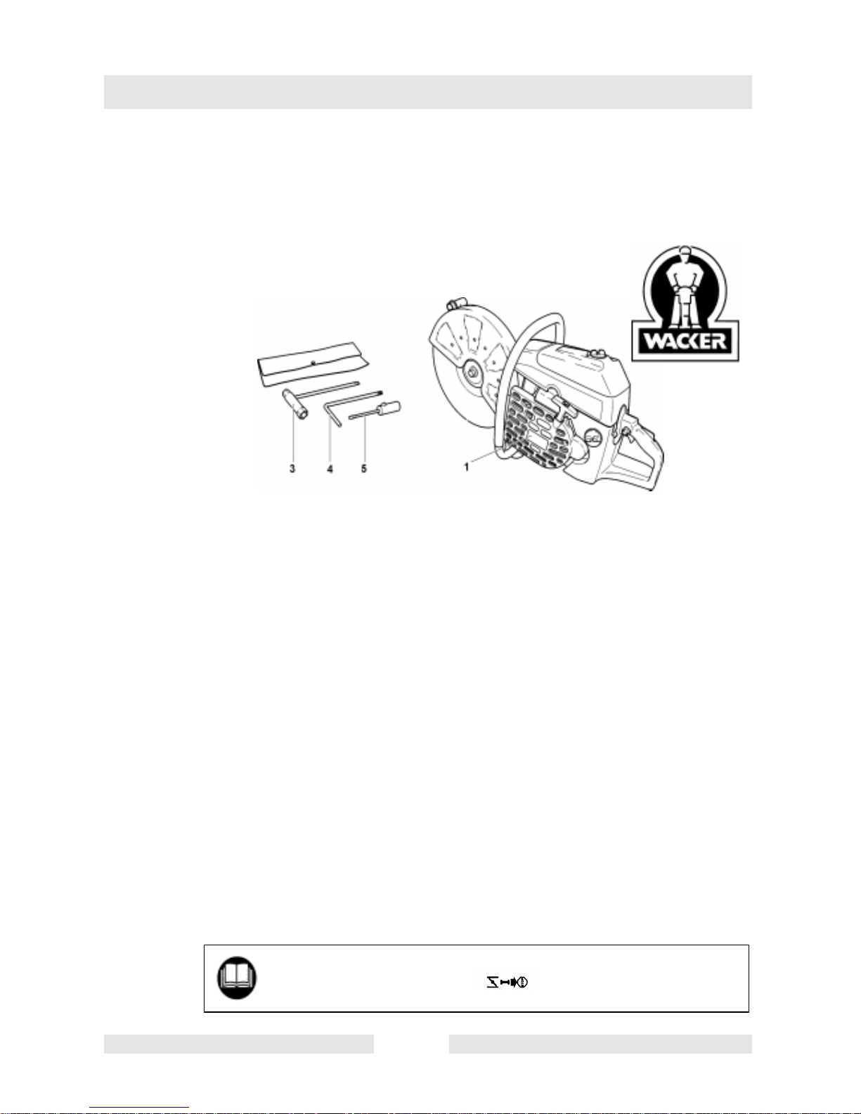
3.1 Delivery Inventory
In case one of the parts listed should not be included in the delivery
inventory, please consult your sales agent!
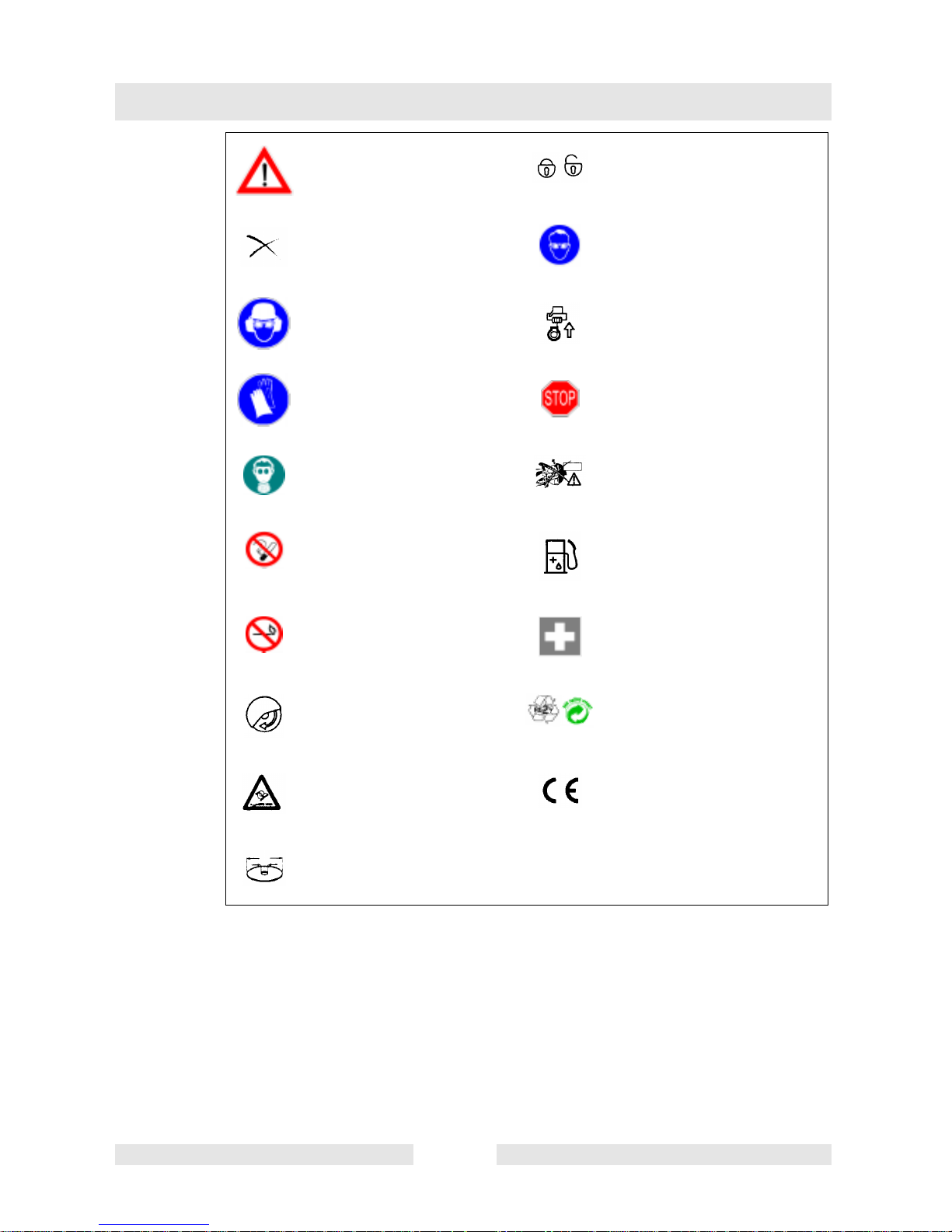
3.2 Symbols
You will notice the following symbols on the saw and in the operator´s
manual:
1. Cut-off saw
3. Universal wrench 13/19
4. Allen key
5. Screwdriver for carburetor adjusment
6. Operator‘s manual (not shown)
Read operator´s manual and
follow the warning and
safety precautions!
CombinationswitchStart/Stop
(I/O), choke
T00961GB 12
Page 15
Delivery Inventory/Symbols
Particular care and caution! Locked / Unlocked
Forbidden! Use eye protection!
Wear protective helmet, eye
and ear protection!
Wear protective gloves! Stop engine!
Wear respiratory protection! Warning! Kickback!
No smoking! Fuel/oil mixture
No open fire! First aid
Turning direction of cutting
blade
Engine - manual start
Recycling
Max. peripheral blade speed CE - marking
Cutting blade dimensions
T00961GB 13
Page 16
Safety precautions
4. Safety precautions
4.1 Use as designed
Cut-off saw
The cut-off saw may only be used for the cutting/shortening of
appropriate materials outdoors with a cutting blade approved for the
machine
Unauthorized working procedure
The cutting blades of the cut-off saw may not be used for grinding
purposes (removal of material with the side face of the cutting blade).
This could cause the blade to fracture! Fitting the cut-off saw with
circular saw discs, knives, brushes etc. is absolutely forbidden.
Non-authorized operators:
Persons who are not familiar with the operator´s manual, children,
teenagers, as well as persons under the influence of alcohol, drugs or
medication are not allowed to operate the machine.
4.2 General precautions
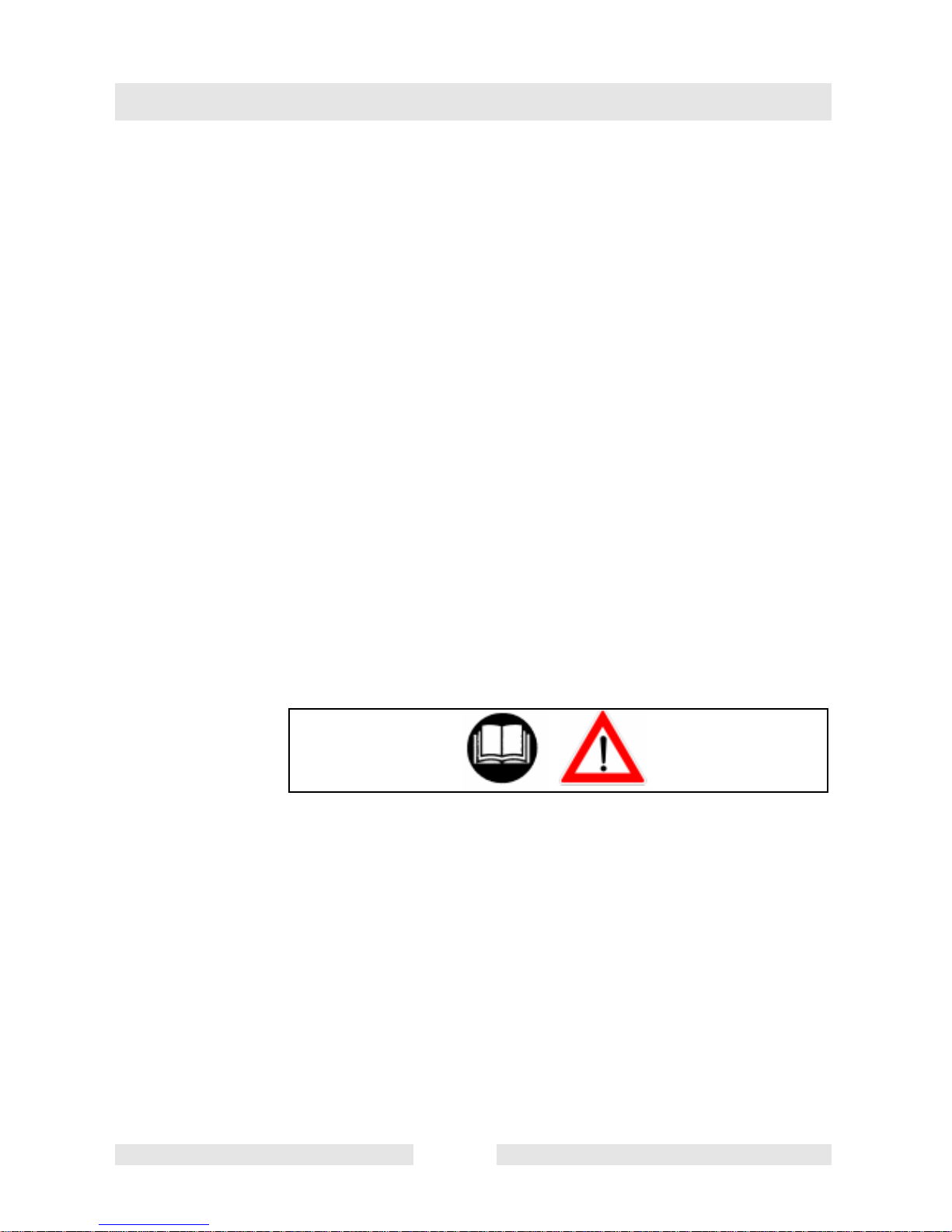
4.2.1 The operator MUST read this manual to ensure safe operation
(even if you already have experience in using cut-off saws), It is
important tobe familiar with the operationof this particular cut-off saw.
Users insufficiently informed will endanger themselves as well as
others due to improper handling.
1
4.2.2 Let only persons who have experience in using cut-off saws work with
this unit. When letting another person use the cut-off saw, this manual
must be provided along with it.
4.2.3 First-time operators should ask a specialist to instruct them in working
with gasoline-powered cut-off saws.
4.2.4 Children and persons under 18 years of age must not be allowed to
use this cut-off saw. Persons over the age of 16 years may, however,
use the cut-off saw for the purpose ofbeing trainedas longas theyare
under the supervision of a qualified trainer.
4.2.5 Working with the cut-off sawrequires high concentration.
4.2.6 Operate the PowerCut only ifyou are ingood physicalcondition. If you
are tired, your attention will be reduced. Be especially careful at the
end of a working day. Perform all work calmly and carefully. The user
has to accept liability for others.
SV00068GB 14
Page 17
4.2.7 Never work while under the influence of alcohol, drugs, medication or
other substances which may impair vision, dexterity or judgement.
2
4.2.8 Ar fire extinguisher must be available in the immediate vicinity when
working in easily inflammable vegetation or when it has not rained for
a long time (danger of fire).
4.2.9 Asbestos and other materials that can release toxins may be cut only
with the necessary safety precautions and after notification of the
proper authorities and under their supervision or that of a person
appointed by them.
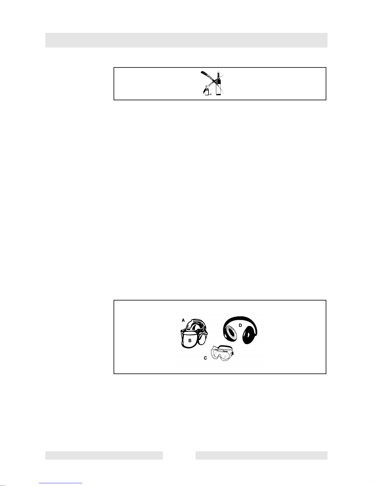
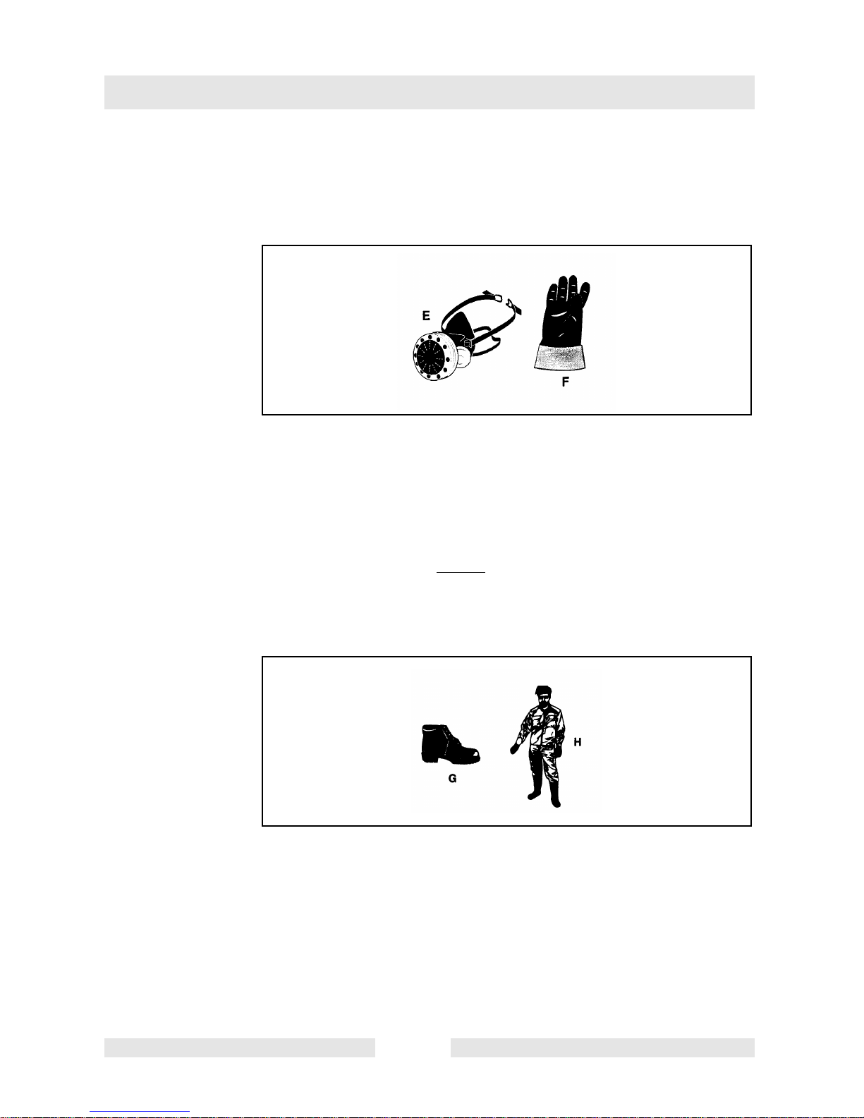
4.3 Personal protective equipment
4.3.1 In order to avoid head, eye, hand or foot injuries as well as to
protect your hearing the following protective equipment must be
used during operation of the cut-off saw:
Safety precautions
4.3.2 The kindof clothing should be appropriate, i. e. itshould be tight-fitting
but not be a hindrance. Clothing in which grains of material can
accumulate (trousers with cuffs, jackets and trousers with wide-open
pockets, etc.) must not be worn, particularly when cutting metal.
4.3.3 Do not wear any jewellery or clothing that can get caught or distract
from the operation of the cut-off saw.
3
4.3.4 It is necessary to wear a protective helmet whenever working with the
cut-off saw. The protective helmet (A) is to be checked in regular
intervals for damage and is to be replaced after 5 years at the latest.
Use only approved protective helmets.
4.3.5 The helmet visor (B) protects the face from dust and material grains.
In order to prevent injuries to eyes and face, always wear protective
goggles (C) or visor when using the cut-off saw.
SV00068GB 15
Page 18
Safety precautions
4.3.6 To prevent hearing damage, always wear suitable personal hearing
protection. (ear muffs (D), ear plugs, etc.). Octave brand analysis
upon request.
4
4.3.7 When dry-cutting dust-producing materials such as stone or concrete,
always wear approved respiratory protection (E).
4.3.8 Work gloves (F) of tough leather are part of the required work kit of
the cut-off saw and must always be worn when working with the cut-off
saw.
5
4.3.9 Always wear safety shoes or boots (G) with steel toes, non-skid
soles, and leg protectors when working with the cut-off saw. Safety
shoes equipped with a protective layer provide protection against cuts
and ensure a secure footing.
4.3.10 Always wear a work suit (H) of sturdy material.
SV00068GB 16
Page 19
4.4 Fuels/Refuelling
4.4.1 Go to a safe, level place before refuelling. Never refuel while on
scaffolding, on heaps of material, or in similar places!
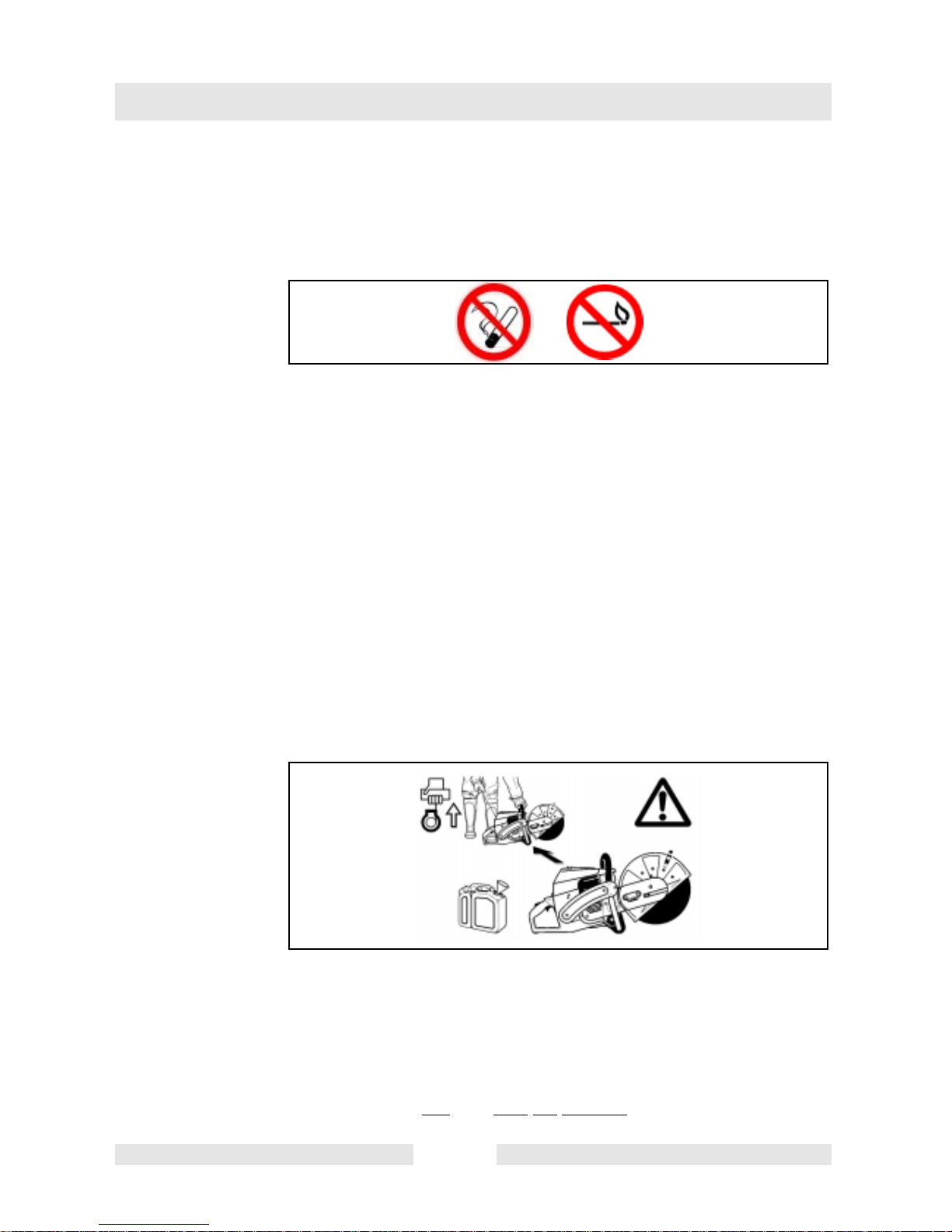
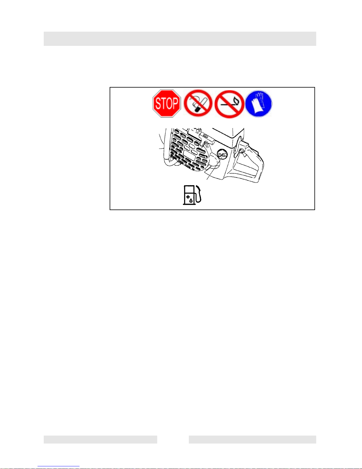
4.4.2 Switch off the engine before refuelling the Power Cut.
6
4.4.3 Do not smoke or work near open fires (6).
4.4.4 Let the engine cool down before refuelling.
4.4.5 Fuelscan contain substancessimilarto solvents. Eyesandskin should
not come in contact with mineral oil products. Always wear protective
gloves when refuelling (notthe regularwork gloves!).Frequently clean
and change protective clothes. Do not breathe in fuel vapors.
Inhalation of fuel vapours can be hazardous to your health.
4.4.6 Do not spill fuel. If a spill occurs, clean off the cutt-off sawimmediately.
Fuel should not come in contact with clothes. If your clothes have
come in contact with fuel, change them at once.
Safety precautions
4.4.7 Ensure that no fuel runs into the soil (environmental protection). Use
an appropriate base.
4.4.8 Refuelling is notallowed in closedspaces. Fuel vaporswill accumulate
near the floor (explosion hazard).
4.4.9 Make sure to firmly tighten the screw plug of the fuel tank.
3 meters
(10 feet)
7
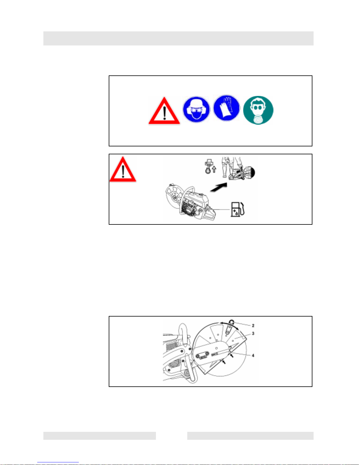
4.4.10 Before starting the engine, move to a location at least 3 meters (10
feet) from where you fuelled the cut-off saw (7), but not within the
extended swing range of the cutting blades (direction of sparks).
4.4.11 Fuel cannot bestoredfor an unlimitedperiodof time. Buyonly as much
as will be consumed in the near future.
4.4.12 When making up the gasoline/oil mixture, always put the oil in the
mixing container
SV00068GB 17
first, and then the gasoline.
Page 20
Safety precautions
4.4.13 Use only approved and marked containers for the transport and
storage of fuel.
Keep fuel away from children!
4.5 Putting into operation
4.5.1 Do not workon your own. There must be someone aroundin case
of an emergency (within shouting distance).
4.5.2 Observe all anti-noise regulations when working in residential areas.
4.5.3 Never use the PowerCut near inflammable materials or explosive
gases! The Power Cut can create sparks leading to fire or
explosion!
30 m(100 feet)
= Wear protective equipment
8
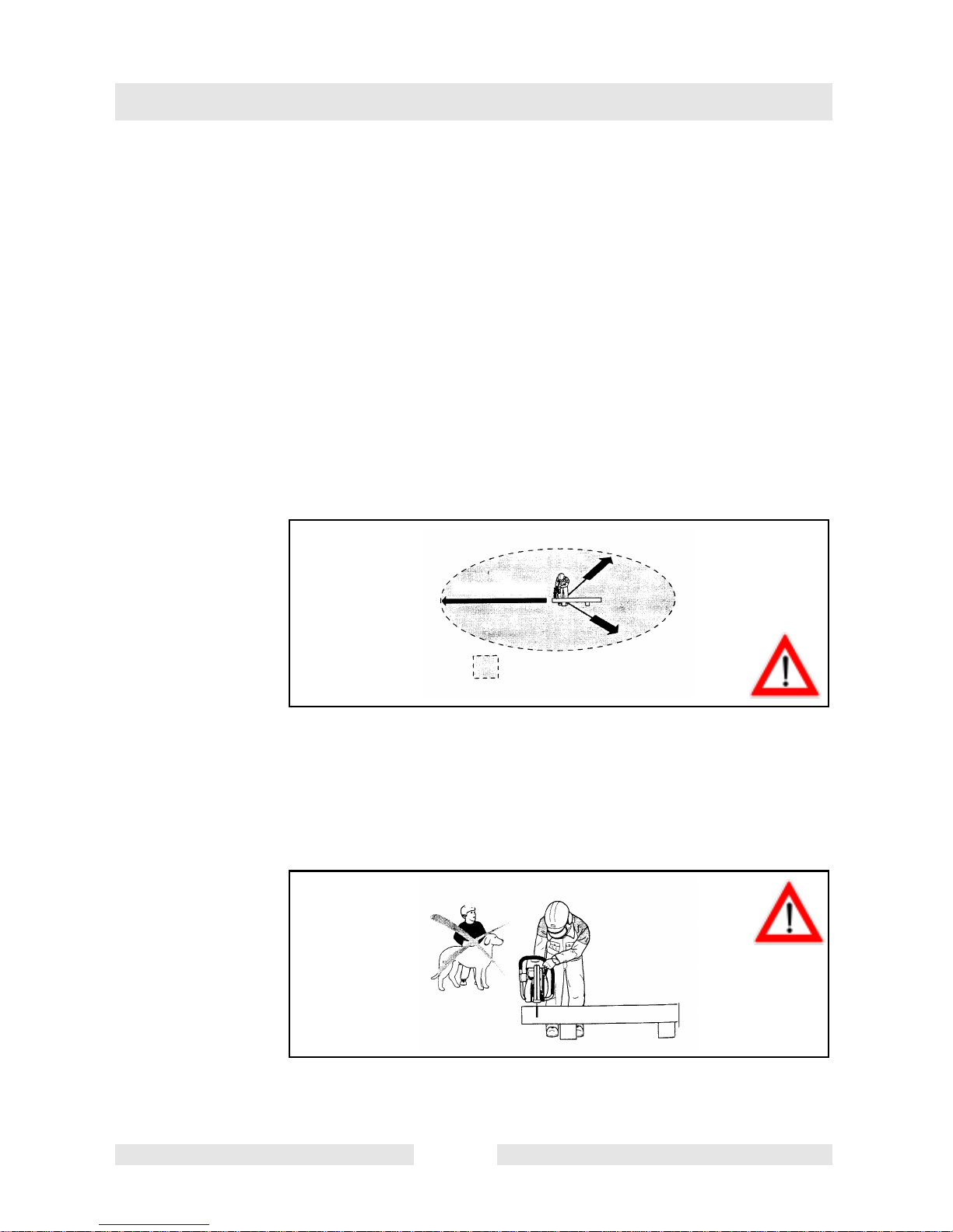
4.5.4 Make sure that all persons within 30 meters (100 feet), such as other
workers, arewearing protective gear (see „Protective Equipment“) (8).
Children and other unauthorized persons must remain more than 30
meters (100 feet) away from the working area. Keep an eye out for
animals as well (9).
9
4.5.5 Before starting work the cut-off saw must be checked for perfect
function and operating safety in aaccordance with regulations.
SV00068GB 18
Page 21
In particular, make sure that the cutting blade is in good conditions
(replace immediately if torn, damaged or bent), the cutting blade is
properlymounted, the protectivehood is lockedinplace, the V-belthas
the proper tension, the throttle moves easily and the half-throttle lock
button functions properly, the handles are clean and dry, and the
combination switch functions properly.
4.5.6 Start the cut-off saw only after complete assembly and inspection.
Never use the cutt-off saw when it is not completely assembled.
4.6 Cutting blades
4.6.1 The protective hood must always be on! Change cutting blades
only with the engine off!
Always make sure to observe the „direction of rotation“ markings.
When using diamond cutting blades.
Safety precautions
10
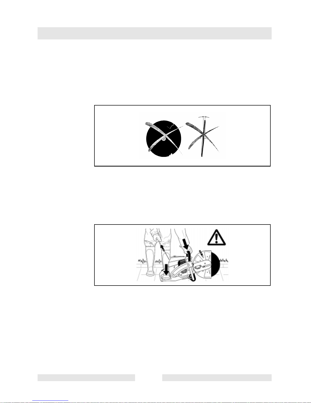
4.6.2 Cutting blades have been designed exclusively for radial loads. Never
use theside face of the cuttingblade for grinding purposes, asthere is
danger of blade fracture.
min. 5 m
(16 feet)
11
ATTENTION!
Never change direction (turning radius less than 5 meters (16
feet), exert lateral (sideways) pressure, or cant the cut-off saw
during cutting applications (11)!
4.6.3 Use a cutting blade only for cutting the materials it is intended for. The
proper type of blade must be selected for either metals or concrete.
SV00068GB 19
Page 22
Safety precautions
4.6.4 The arbour hole (bore) of the cutting blade must fit the shaft exactly. If
the arbour hole islarger thanthe shaftdiameter, aspacer ringmust be
used.
4.6.5 Free-hand cutting blades with a blade diameter of 355 mm (14“) must
be approved for speeds of up to 4370 1/min (rpm) or80 m/s (260 ft./
sec); blades with a blade diameter of 300 mm (12“) must be approved
for speeds of up 5100 1/min (rpm) or 80 m/s (260 ft./sec).
12
4.6.6 The cutting blade must be free of defects (12). Make sure by sound
testing with a piece of wood. Do not use defective cutting discs.
Always tighten the cutting blade‘s mounting bolt to a torqueof 30
Nm (22.2ft.lbs.). Otherwise, the cutting blade could warp.
4.6.7 Make sure you have a steady footing before starting the cutting blade.
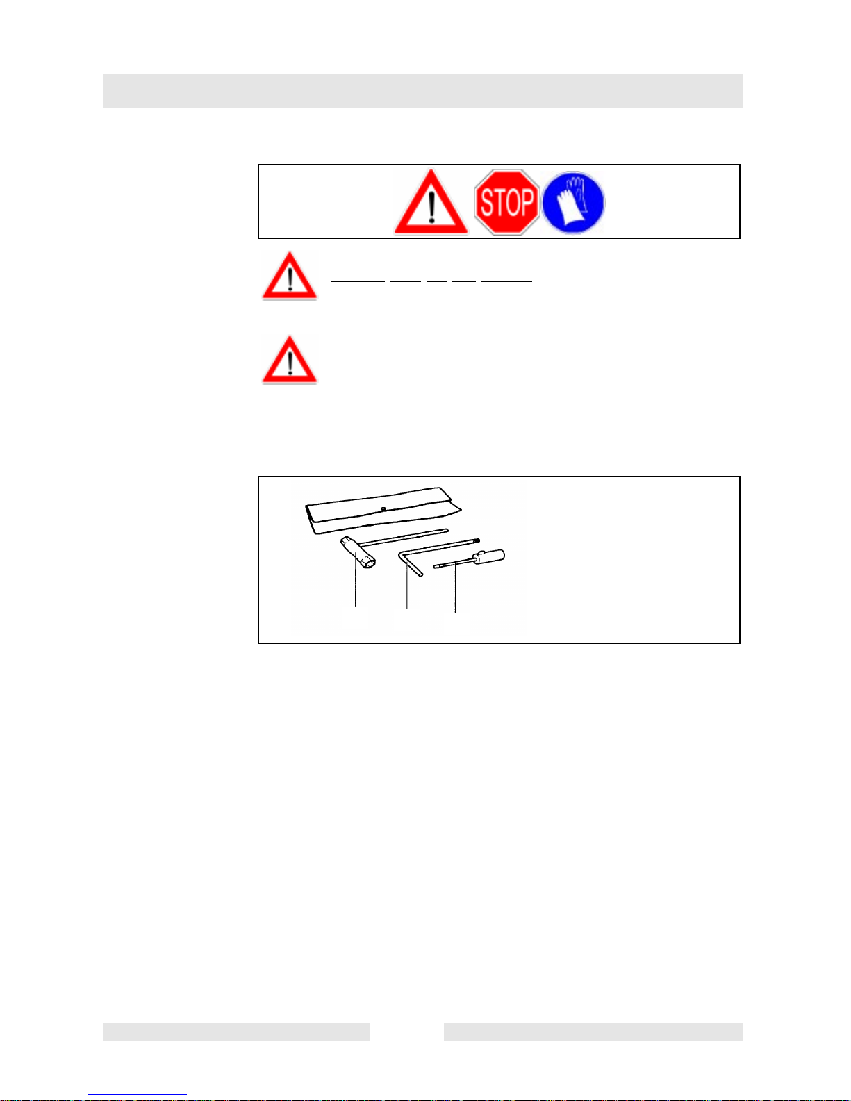
13
4.6.8 Put the cut-offsawinto operationonlyas described inthis manual (13).
Always place your left foot in the rear handle and grasp the other
handle firmly (with thumb and fingers). Other starting methods are not
allowed.
4.6.9 When starting the cut-off saw it must be well supported and securely
held. The cutting blade must not be touching anything.
4.6.10 If the cutting blade is new, test it by running it at least 60 seconds at
top speed. When doing this, make sure that no persons or body parts
are in the extended swing range of the cutting blade, in case it is
defective and flies apart.
SV00068GB 20
Page 23

Safety precautions
4.6.11 When working with the cut-off saw always hold it with both
hands. Take the back handle with the right hand and the tubular
handle with the left hand. Hold the handles tightly with your thumbs
facing your fingers.
4.6.12 ATTENTION: When yourelease the throttlelever the cutting blade
will keep spinning for a short period of time (free-wheeling effect.).
4.6.13 Always make sure that you have a safe footing.
4.6.14 Hold the cut-off saw such that you will not breathe in the exhaust gas.
Do not work in closed rooms or in deep holes or ditches (danger of
poisoning by fumes).
4.6.15 Immediately switch off the cut-off saw if you observe any
changes in its operating behavior.
*
Maintenance
*
Refuelling
*
Replacing the cutting blade
*
Repositioning the cutting arm
*
Work pause
*
Transport
*
14
Out of operation
4.6.16 Stop the engine (14) before checking the V-belt‘s tension or
retightening the V-belt, before replacing a cutting blade, before
changing the cutting arm (inboard to outboard or vice versa) and
before eliminating malfunctions.
4.6.17 Turn off theengine immediately andcheck the cuttingblade ifyou hear
or feel any change in cutting behaviour.
4.6.18 Turn off the cut-off saw when taking a break or stopping work (14).
Place the unit in such a way that the cutting blade is not touching
anything and cannot endanger anyone.
4.6.19 Do not put the overheated cut-off saw in dry grass or on any
inflammable objects. The muffler is very hot (danger of fire).
4.6.20 ATTENTION: After wet cutting,first turnoff thewater feed and then let
the blade run at least another 30 seconds, to fling off the remaining
water and prevent corrosion.
SV00068GB 21
Page 24

Safety precautions
4.7 Kickback and lock-in
4.7.1 There is a danger of kickback and lock-in. When working with the cutoff saw.
15
4.7.2 Kickback occurs when the top of the cutting blade is used for cutting
(15).
4.7.3 This causes the cut-off saw to be thrown back toward the user with
great force and out of control. Risk of injury!
To prevent kickback, observe the following:
4.7.4 Never cut with the section of the cutting blade shown in figure 15.
Be especially carefulwhen reinserting the discinto cuts thathave
already been started!
4.7.5 Lock-in occurs when the cut narrows (crack, or workpiece under
stress).
4.7.6 This causes the cut-off saw to suddenly jump forward, out of control
and with great force. Risk of injury!
To prevent lock-in, observe the following:
4.7.7 When reinserting the disc into previous cuts, have the cut-off saw
running at top speed. Always cut at top speed.
16
4.7.8 Always support the workpiece so that the cut is under pulling tension
(16), so that the cut does not press together and jam the cutting blade
as it proceeds through the material.
SV00068GB 22
Page 25

4.7.9 When starting a cut, applythe cuttingblade tothe workpiece with care.
Do not just shove it into the material.
4.7.10 Never cut more than onepiece ata time! When cutting, make sure that
no other workpiece is touched.
4.8 Working behavior/Method of working
4.8.1 Before starting work, check the work area for any hazards (electrical
wires, inflammable substances). Clearly mark the work area (for
example with warning signs or by cordoning off the area).
4.8.2 When working with the cut-off saw hold it firmly by the front and rear
handles. Never leave the cut-off saw unattended!
4.8.3 Whenever possible run the cut-off saw at the rated arbour speed (see
„Technical Data“).
Safety precautions
4.8.4 Only use the cut-off saw during good light and visibility periods. Be
aware of slippery or wet areas, and of ice and snow (risk of slipping).
4.8.5 Never work on unstable surfaces. Make sure that there are no
obstacles in the working area, risk of stumbling. Always ensure that
you have a safe footing.
17
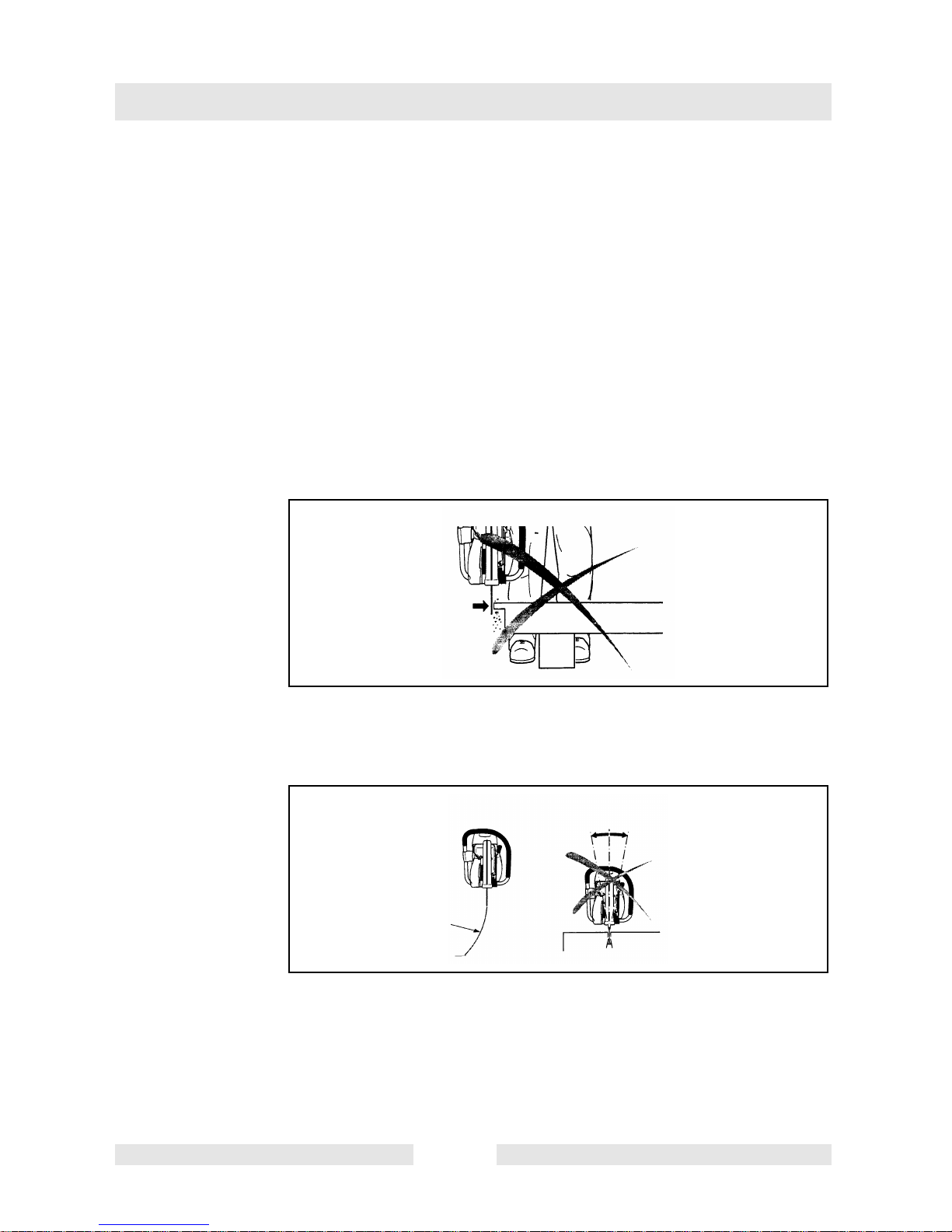
4.8.6 Never cut above your shoulder height (17).
4.8.7 Never stand on a ladder to cut (17).
4.8.8 Never use the cut-off saw while standing on scaffolding.
4.8.9 Do not lean over toofar whenworking. Whenputting down and picking
up the cut-off saw, do not bend over from the waist, but instead bend
in the knees. Save your back!
SV00068GB 23
Page 26

Safety precautions
18
4.8.10 Guide the cut-off saw in such a way that no part of your body is within
the extended swing range of the blade (18).
4.8.11 Use cutting blades only for the materials for which they are designed!
4.8.12 Do not use thecut-off saw to lift up and shovel away piecesof material
and other objects.
Important injury hazard! Before cutting, remove all foreign objects,
such asrocks, gravel, nails etc. fromthe cutting area. Otherwise, such
objects can be flung away by the blade with great speed.
4.8.13 When cutting workpieces down to length use a firm support. If
necessary, secure the workpiece from slipping, but do not steady it
with your foot or allow another person to hold it.
4.8.14 When cutting round items, always secure them against rotation.
4.8.15 When guiding the cut-off sawby hand,use the outboard position of the
cutter arm only when actually necessary. Otherwise, always use the
inboard position. This gives the unit a better balance, for reduced
operator fatigue.
4.9 Cutting metals
ATTENTION!
Always wear approved respiratory protection!
Materials that can release toxic substances may be cut only after
notifying the proper authorities and under their supervision or
that of a person appointed by them.
SV00068GB 24
Page 27

Safety precautions
19
CAUTION!
The rapid rotation of the cutting blade heats metal and melts it at
the point of contact. Swing the guard as far down as possible
behind the cut(19) in order to directthe stream ofsparks forward,
away from the operator (fire hazard).
4.9.1 Determine the direction of cutting, mark the cut and apply the blade to
the material at moderate speed, to cut a guide groove before going to
top speed and applying more pressure to the cut-off saw.
4.9.2 Keep the blade straight and vertical. Do not tip it, as this can break it.
4.9.3 The bestway to get a good, clean cut is to pull or move the cut-off saw
back and forth. Do not simply press the blade into the material.
20
4.9.4 Thick round stock is best cut in stages (20).
4.9.5 Thin tubing and pipes can be cut with a simple downward cut.
4.9.6 Treat large-diameter pipes as round stock. To prevent tipping and for
better control, do not let the blade sink too deeply into the material.
Instead, always cut shallow around the whole piece.
4.9.7 Worn blades have a smaller diameter than new blades, so that at the
same engine speed they have a lower effective circumferential speed
and therefore do not cut as well.
SV00068GB 25
Page 28

Safety precautions
21
4.9.8 Cut I-beams and L-bars in steps; see Figure 21.
4.9.9 Cut bands and plates like pipes: along the wide side with a long cut.
22
4.9.10 When cutting material under stress (supported material or material in
structures), always make a notch in the thrust (pressure) side, and
then cut from the tension side, so that the blade does not lock in (22).
Secure cutoff material from falling!
ATTENTION!
If there is a chance that the material is under stress, be prepared
for it to kick back. Make sure you can get out of the way if you
have to!
Be particularly careful in scrap-metal yards, junkyards, at
accident sites, and with haphazard piles of material. Precariously
balanced pieces or pieces under stress can act in unpredictable
ways, and may slide, jump out, or burst. Secure cutoff material
from falling (22)! Always exercise extreme caution and use only
equipment that is in perfect working order.
Observe the accident-prevention rules and regulations of your
employer and/or insurance organization.
SV00068GB 26
Page 29

Safety precautions
4.10 Cutting masonry concrete, asbestos or asphalt
ATTENTION!
Always wear approved respiratory protection!
Asbestos and other materials that can release toxic substances
may be cut only after notifying the proper authorities and under
their supervision or that of a person appointed by them. When
cutting prestressed and reinforced concrete piles, follow the
instructions and standards of the responsible authorities or the
builder of thestructural member. Reinforcement rodsmust be cut
in the prescribed sequence and in accordance with applicable
safety regulations.
NOTE!
Mortar, stone, and concrete develop large quantities of dust during
cutting. To increase the lifetime of the cutting blade (by cooling), to
improve visibility, and to avoid excessive dust creation, we strongly
recommend wet cutting instead of dry cutting.
In wet cutting, the blade is watered at an equal rate on both sides by a
trickle of water.WACKERoffers therightaccessories for allwet cutting
applications (see also “SPECIAL ACCESSORIES“).
4.10.1 Remove foreign objects such as sand, stones and nails found within
the working area.
Caution: Watch out for electric wires and cables!
23
The rapid rotation of the cutting blade at the point of contact
throws fragments out of the cut groove at high speed. For your
safety, swing the protective hood down as far as possible behind
the cut (23), so that material fragments are thrown forward, away
from the operator.
4.10.2 Mark the cut, and then make a groove about 5 mm deep (just under
0,2“) along the entire length of the planned cut. This groove will then
guide the cut-off saw accurately guring the actual cutoff.
SV00068GB 27
Page 30

Safety precautions
24
NOTE:
For long, straight cuts we recommend using a guide cart (24, see also
“SPECIAL ACCESSORIES“). This makes it much easier to guide the
unit in a straight line with less effort.
25
4.10.3 Whencutting slabs tosize, you neednotcut through theentirematerial
thickness (creating unnecessarydust). Instead, simplymake a shallow
groove, and thenknockoff theexcessmaterial cleanly ona flat surface
(25).
ATTENTION!
When cutting into lengths, cutting through material, making cutouts,
etc., always make sure to plan the direction and sequence of cuts in
such a way that the blade does not get jammed by the cut-off piece,
and that no persons can be injured by falling pieces.
SV00068GB 28
Page 31

4.11 Transport and storage
26
4.11.1 Always turn off the cut-off saw when transporting it or moving it
from place to place on a site (26).
4.11.2 Never carry or move the unit with the engine running or the blade
turning!
4.11.3 Carry the unit only bythe tubular(middle) handlewith the cutting blade
pointing behind you (26). Avoid touching the exhaust muffler (burn
hazard!).
Safety precautions
4.11.4 When moving the cut-off saw over longer distances, use a
wheelbarrow or wagon.
4.11.5 When transporting the cut-off saw in a vehicle, make sure it is securely
positioned in such a way that no fuel can leak out. Always remove the
cutting blade before transporting the unit in a vehicle.
4.11.6 The cut-off saw should be stored safely in a dry place. It must not be
left outdoors! Always dismount the cutting blade before storage. Keep
the cut-off saw away from children.
4.11.7 Before long-term storage and before shipping the cut-off saw ,
follow the instructions in the chapter on “Periodic care and
maintenance“. ALWAYS empty the fuel tank and run the
carburetor dry.
4.11.8 When putting cutting bladess in storage, be careful to:
4.11.9 Clean and dry them well.
4.11.10 Store them lying down flat.
4.11.11 Avoid dampness, freezing temperatures, direct sunshine, high
temperatures and temperature fluctuations, as these can cause
breakage and splintering.
4.11.12 Always check new cutting blades or blades that have been in
storage to make sure that they are free of defects.
SV00068GB 29
Page 32

Safety precautions
4.12 Maintenance
27
4.12.1 Switch off the cut-off saw (27) and pull out the plug cap Before
performing maintenance work.
4.12.2 Always check the cut-off saw before using it to make sure that it is in
good working order. In particular, make sure that the cutting blade is
properly mounted.Make surethat the cutting blade is undamaged and
suitable for the job it will be used for.
4.12.3 Operate the cut-off saw only at a low noise and emission level. Forthis
ensure the carburetor is adjusted correctly.
4.12.4 Clean the cut-off saw regularly.
4.12.5 Check the fuel tank cap regularly for good sealing.
Ovserve the accident prevention instructions issued by trade
associations and insurance companies. NEVER make any
modifications to the cut-off saw! You will only be putting your
own safety at risk!
28
SERVICE
Perform only the maintenance and repair works described in the
operator‘s manual. All other work must be carried out by WACKER
Service.
Use only original WACKER spares and accessories.
The use of non-WACKER spares, accessories, or cutting blades
increases the risk of accident. We cannot accept any responsibility for
accidents or damage occurring in association with the use of
accesories other than original WACKER.
SV00068GB 30
Page 33

4.13 First aid
For the event of a possible accident, please make sure that a first aid
kit is always immediately available close by. Immediately replace any
items used from the first aid box.
When calling for help, give the following information:
∗ Place of the accident
Safety precautions
29
∗ What happened
∗ Number of injured people
∗ Kind of injuries
∗ Your name!
NOTE!
Individuals with circulatory problems who are exposed to excessive
vibration may experience injury to blood vessels or the nervous
system.
Vibration may cause the following symptoms to occur in the fingers,
hands or wrists: “Falling asleep“ (numbness), tingling, pain, stabbing
sensation, alteration of skin colour or of the skin.
If any of these symptoms occur, see a physician!
SV00068GB 31
Page 34

Technical data
5. Technical data
Item no. 0008987 ... 0008988 ...
Displacement cm3 (cu in) 64 (3,9)
Bore mm (in) 47 (1,85)
Stroke mm (in) 37 (1,46)
Max. power kW (hp) 3,3 (4,5)
Max. torque Nm (ft.lbs.) 4,0 (3,0)
Idling speed 1/min [rpm] 2.500
Clutch engagement speed 1/min [rpm] 3.800
Engine speed limitation 1/min [rpm] 9.350
shaft speed 1/min [rpm] 4.300
Sound pressure level L
Sound power level L
Vibration acceleration a
- Tubular handle (idle/rated spindle speed)
- Rear handle (idle/rated spindle speed)
Carburetor (diaphragm carburetor) Typ (Type) TILLOTSON HS-273 A
Ignition system (with speed limitation) Typ (Type) electronic
Spark plug Typ (Type) NGK BPMR 7A / BOSCH WSR 6F /
Electrode gap mm (in) 0,5 (.020)
Fuel consumption at max. load per ISO 8893 l/h
Specific consumption at max. load per
ISO 8893
Fuel tank capacity l (US qt) 1,1 (1,2)
Mixture ratio fuel/two-stroke oil5)
Cutting blade fer max. 80 m/s (260 ft/sec.)2)
Arbor diameter mm (in) 20,0 (0,787“) 25,4 (1“)
Weight cut-off saw (empty tank, no blade) kg
per EN 1454
pA eq
per EN 1454
h,w
1) 4)
BTS 930L3 BTS 935L3
dB (A) 97
WA
2
m/s
CHAMPION RCJ 6Y
(US qt/h)
g/kWh
(oz./hph)
mm (in) 300 / 20,0 / 5
(12/0,787/0,2)
10,0
(lb)
(22)
109 db(A)
6 / 5
8 / 6
2,1
(2,2)
500
(13)
50:1
3)
350 / 25,4 / 5
3)
(14/1/0,2)
10,2
(22,5)
1
) Figures derived in equal part from idle and max.-speed operation.
2
) Circumference speed at max. engine speed.
3
) Outside diameter/arbor hole/thickness.
4
) At the workplace (at user‘s ear).
5
) With 2-cycle engine oil according to API TC, JASO FC. or ISO L-EGD
TD00676GB 32
Page 35

Technical data
BTS 1030L3 BTS 1035L3
Item no. 0008989 ... 0008990 ...
Displacement cm3 (cu in) 73 (4,5)
Bore mm (in) 50 (1,97)
Stroke mm (in) 37 (1,46)
Max. power kW (hp) 4,2 (5,7)
Max. torque Nm (ft.lbs.) 5,0 (3,7)
Idling speed 1/min [rpm] 2.500
Clutch engagement speed 1/min [rpm] 3.800
Engine speed limitation 1/min [rpm] 9.350
spindle speed 1/min [rpm] 4.300
Sound pressure level L
4)
pA eq
per EN 1454
1)
Sound power level L
Vibration acceleration a
per EN 1454
h,w
- Tubular handle (idle/rated spindle
speed)
- Rear handle (idle/rated spindle speed)
Carburetor (diaphragm carburetor) Typ (Type) TILLOTSON HS-273 A
Ignition system (with speed limitation) Typ (Type) electronic
Spark plug Typ (Type) NGK BPMR 7A / BOSCH WSR 6F /
Electrode gap mm (in) 0,5 (.020)
Fuel consumption at max. load per
ISO 8893
Specific consumption at max. load per
ISO 8893
Fuel tank capacity l (US qt) 1,1 (1,21)
Mixture ratio fuel/two-stroke oil5)
Cutting blade fer max. 80 m/s (260 ft/sec.)
2
)
Arbor diameter mm (in) 20,0 (0,787“) 25,4 (1“)
Weight cut-off saw (empty tank, no blade) kg ( lb) 10,0 (22) 10,2 (22,5)
dB (A) 99
110 db(A)
7 / 5
8 / 7
m/s
WA
2
CHAMPION RCJ 6Y
l/h (US qt/h) 2,7 (2,9)
g/kWh
(oz./hph)
500
(13)
50:1
mm (in) 300/20,0/5
(12/0,787/0,2)
3)
350/25,4/5
(14/1/0,2)
3)
1
) Figures derived in equal part from idle and max.-speed operation.
2
) Circumference speed at max. engine speed.
3
) Outside diameter/arbor hole/thickness.
4
) At the workplace (at user‘s ear).
5
) With 2-cycle engine oil according to API TC, JASO FC. or ISO L-EGD
TD00676GB 33
Page 36

Denomination of components
6. Denomination of components
Identification plate
Indicate when ordering spare parts!
T00962GB 34
Page 37

Denomination of components
1 Handle
2 Filter cover for air filter and spark plug cap
3 Cover lock
4 Tubular handle
5 Muffler
6 Protective hood
7 Protective hood handle
8 V-belt tension adjusting screw
9 Retaining nuts
10 Base
11 Carburetor adjustment opening
12 Identification plate
13 Fuel tank with handle
14 Starter grip
15 Combination switch Start/Stop (I/O), choke
16 Stop knob for halfway throttle
17 Safety locking button
18 Throttle lever
19 Fuel tank plug
20 Fan housing with starting assembly
21 Cutting blade
22 Cutting blade fastening bolt
23 Spring washer
24 Lock bore for V-belt pulley
T00962GB 35
Page 38
Putting into operation
7. Putting into operation
30
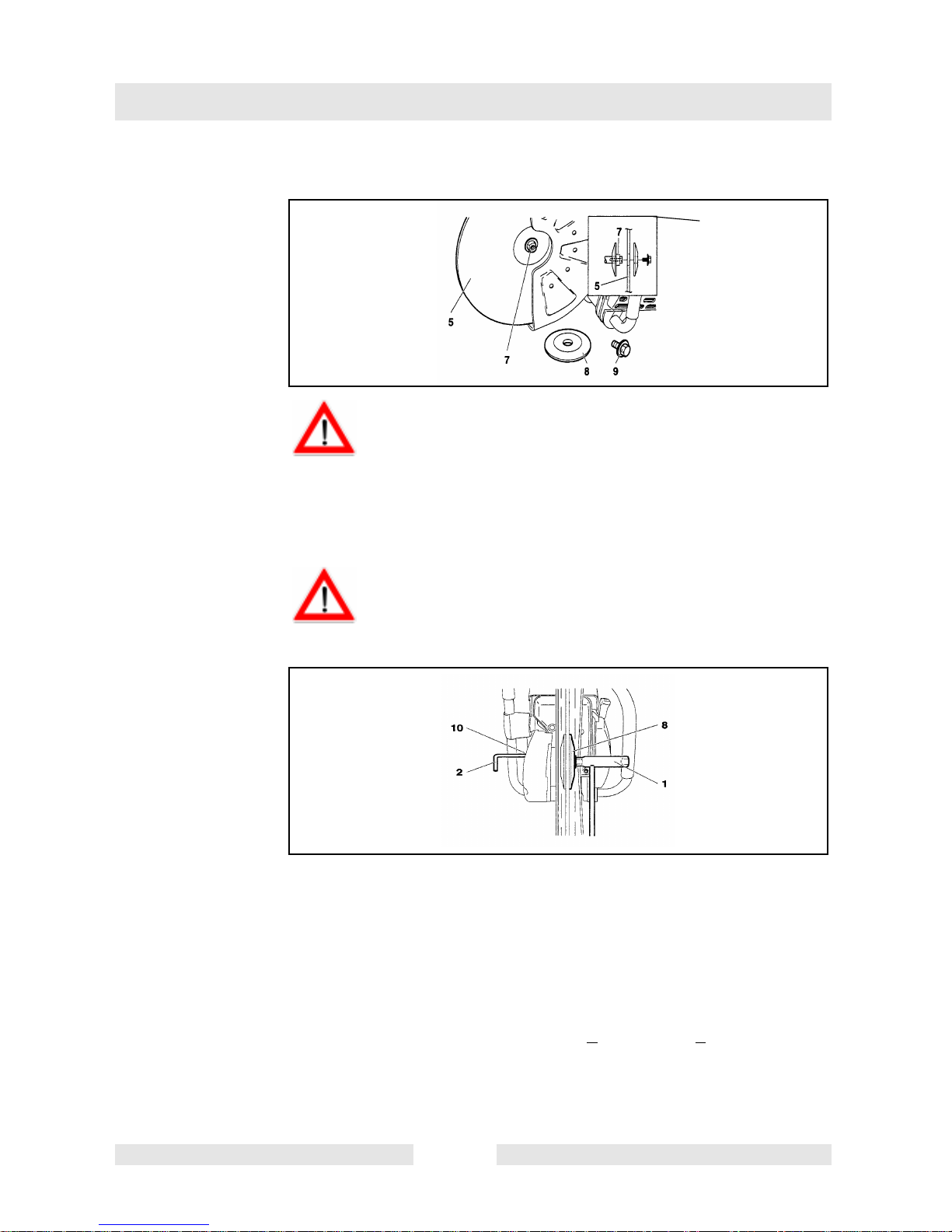
For the the following work, use the assembly tools included with
delivery:
ATTENTION:
Always turn off the engine and pull off the spark plug
cap before doing any work on the cut-off saw! Always
wear protective gloves!
ATTENTIONE:
Start the cut-off saw only after complete assembly and
inspection.
1.13/19 AF universal wrench
2. Allen key
3. Carburetor adjustment
screwdriver
31
1
2
3
Place the cut-off saw on a stable surface and carry out the following
assembly steps:
T00962GB 36
Page 39
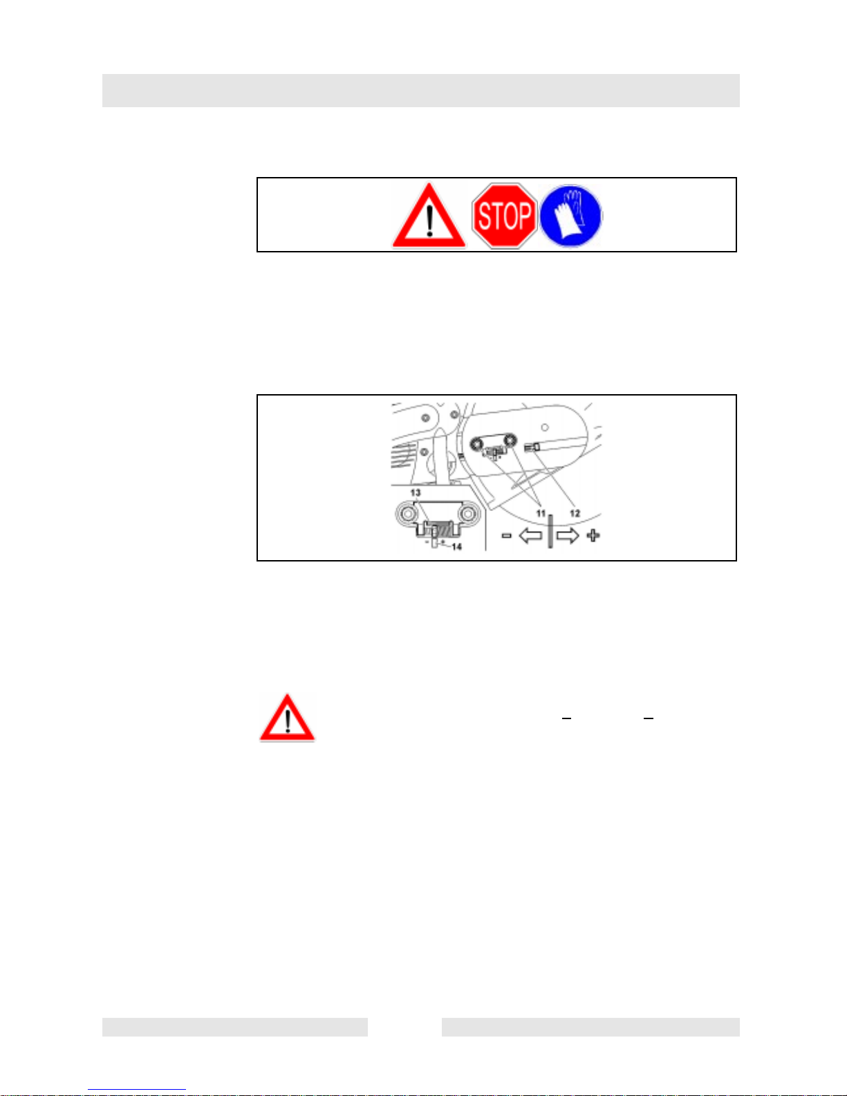
7.1 Fitting cutting blades
32
Inspect the disc for damage, see SAFETY
INSTRUCTIONS. Unscrew screw (9)andremove the spring
washer (8). Place the cutting disc (5) on the arbour (7).
NOTE: The arbor hole of the cutting disk must fit the shaft precisely.
Use an adapter ring to compensate for a larger arbor hole.
Putting into operation
Model
ATTENTION:
When using a diamond cutting disc be sure to mount it so
that it rotates in the proper direction!
33
Place the spring washer (8) on the arbour and insert the screw (32/9)
and tighten by hand.
Slowly turn the cutting disc until the stop hole of the V-belt wheel is
visible in the cutting arm hole (10). Insert the Allen key (2) as far as it
will go. The shaft is now blocked.
Tighten the screw with the combination wrench (1).
NOTE: Tighten the screw firmly 30
otherwise the cutting wheel could slip during cutting applications.
T00962GB 37
+2Nm(22+ 1,5 ft.lbs.), as
Page 40
Putting into operation
7.2 Tightening the V-belt/Checking V-belt tension
34
ATTENTION:
Exact V-belt tension is essential for maximum cutting
performance with minimum fuel consumption. Improper V-belt
tension will result in premature wear to the V-belt and V-belt
pulley or damage to theclutch bearing. Retighten new V-beltafter
first running hour!
35
NOTE: The two fastening nuts (11) must be loosened before
tightening the V-belt or checking the tension.
To increase the belt tension, turn the tightening screw (12) to the right
(clockwise) with the combination wrench included with the cut-off saw
The belt tension is correctly adjusted when the nut (13) is centred on
the mark (14).
ATTENTION: After tightening/inspection, make certain to
tighten the fastening nuts (11) 30
+ 2 Nm (22 + 1,5 ft.lbs.).
T00962GB 38
Page 41

7.3 Fuels
Putting into operation
ATTENTION:
The cut-off saw uses mineral-oil products (gasoline and oil).
Be especially careful when handling gasoline.
Do not smoke. Do not allow gasoline to come near flames, sparks
or fire (explosion hazard).
Gasoline 50:1
+
1000 cm
5000 cm
3
(1 liter) 20 cm
3
(5 liter) 100 cm
10000 cm3(10 liter) 200 cm
Us-gal.1,0 2,5 fl.oz.
Us-gal.2,5 6,4 fl.oz.
Us-gal.5,0 12,8 fl.oz.
The correct mixture ratio:
50:1 50 parts gasoline to 1 part oil.
36
Fuel mixture
The cut-offsaw ispowered by a high-performance two-cycle engine. It
runs on a mixture of gasoline and two-cycle engine oil.
The engine is designed for unleaded regular gasoline with a min.
octane valueof 91 ROZ. In case no suchfuel is available, you canuse
fuel with a higher octane value. This will not affect the engine.
3
3
3
In order to obtain an optimum engine output and to protect your
health and the environment use unleaded fuel only.
T00962GB 39
Page 42

Putting into operation
The 2-cycle engine oil must comply with API TC, JASO FC or ISO LEGD specifications.
NOTE: Forpreparing the fuel-oil mixture firstmix the entire oil quantity
with half of the fuel required, then add the remaining fuel. Shake the
finished mixture thoroughly before pouring it into the saw‘s tank.
ATTENTION: Open the tank cap carefully, as pressure might have
built up inside!
It is not wise to add more engine oil than specified to ensure safe
operation. This will only result in a higher production of
combustion residues which will pollute the environment and clog
the exhaust channel in the cylinder as well as the muffler. In
addition, fuel consumption will rise and performance will
decrease.
7.4 Fuel storage
Fuels have only a limited shelf-life. Buy only as much as you will use
in 4 weeks.
Only store fuel in approved and marked containers.
37
AVOID SKIN AND EYE CONTACT
Mineral oil products degrease your skin. If your skin comes in contact
with these substances repeatedly and for an extended period of time,
it will dry out. Various skin diseases may result. In addition, allergic
reactions are known to occur.
Eyes can be irritated by contact with oil. If oil comes into your eyes,
immediately wash them with clear water.
If your eyes are still irritated, see a doctor immediately!
T00962GB 40
Page 43
7.5 Refuelling
Putting into operation
38
Fuel mixture
ATTENCION: FOLLOW THE SAFETY PRECAUTIONS BY ALL
MEANS!
Be careful and cautious when handling fuels.
The engine must be turned off and cooled down!
Carefully clean the area around the fuel-tank filler neck to keep dirt
from getting in the tank.
Place the unit on its side on an even surface.
Unscrew the tank capand filltank withfuel mixture.Take careto avoid
spilling.
Tightly screw on the plug.
Clean tank cap and surrounding area after refuelling. Never start
or operate the cut-off saw in the same place as it was fuelled!
T00962GB 41
Page 44
Putting into operation
7.6 Starting the engine
if
39
3 meters
(10 feet)
40
ATTENCION:
Observe the SAFETY INSTRUCTIONS under all circumstances!
Start the cut-off saw only after complete assembly and
inspection!
Move at least 3 m (10feet) away from the place where you fuelled
the cut-off saw.
Make sure you have a good footing, and place the cut-off saw on
the ground in such a way that the cutting disc is not touching
anything.
necessary
41
Turn protective hood (3) to optimum position according to cutting
application (see drawing).
Grab handle (2) and move protective hood (3) to any position desired
between stops in either direction..
T00962GB 42
Page 45

ATTENCION:
By all means make sure that outer edge of stop plate (4) is parallel to
the edge of the protective hood (see arrows).
Visit a specialized work shop if this should not be the case.
7.7 Cold-starting
42
Putting into operation
Move the combination switch (5) upwards (choke position).
Grasp handle (hand pressure actuates the grip throttle lever lock (7)).
Push the throttle (8) in all the way and hold it.
Press the throttle lock (6) and release the throttle (8) (the throttle lock
will hold the throttle at half-throttle position).
43
Grasp the tubular handle firmly with one hand and press the cut-off
saw firmly against the ground:
Place the tip of your left foot in the rear handle.
Slowly pull out thestarter ropeuntil younotice resistance (the piston is
positioned before the top dead centre).
Now pull the starter rope with a fast and forceful movement until you
hear the first ignition.
T00962GB 43
Page 46

Putting into operation
ATTENCION: Do notpull outthe starter ropemore thanapprox. 50 cm
(20 feet), and lead it back by hand.
Move the combination switch (42/5) to the position “I“.
Keep pulling the starter rope until the engine starts running.
As soon as the engine is running, press the throttle (42/8) to release
the half-throttle lock (42/6), allowing the engine to idle.
7.8 Warm-starting
As described under „Cold starting“, except without moving the
combination switch (42/5) to the choke position.
7.9 Stopping the engine
44
Push the combination switch (9) down to position
7.10 Adjusting the carburetor
45
NOTE: The cut-off saw has been equipped with an
electronic ignition to limit the speed. The carburetor
also has a fixed jet which cannot be adjusted.
At the factory the idling speed has been set to approx.
2.500 1/min, but the running-in process of a new engine may
require slight readjustment of the idling speed.
Set the idling speed with a screwdriver (width
of blade: 4 mm) (0,16“).
The screwdriver shown has a molded-on lugto
assist in adjustment.
T00962GB 44
Page 47

Putting into operation
46
The following steps must be carried out: For the correct
adjustment of the idling speed
Start the engine and run it until it is warm (about 3 - 5 minutes).
47
Carry out carburetor adjustment with the scope of delivery.
Readjusting the idle speed
Proceed as follows if the cutting blade is turning while the engine is
idling: turn thethrottle valve‘s stopscrews (2) outwardsuntil thecutting
blade stops moving. Turn the screw back in if the engine stops running
while idling.
Stop engine
T00962GB 45
Page 48

Maintenance
8. Maintenance
48
ATTENCION
Before doing any work on the cut-off saw turn off the engine,
remove the cutting blade, pull the plug cap off the spark plug and
wear protective gloves!
ATTENCION
Start the cut-off saw only after complete assembly and
inspection.
49
SERVICE
NOTE
Because many of the parts and assemblies not mentioned in this
Instruction Manual are vital to the safety of the unit, and because
all parts are subject to a certain amount of wear and tear, it is
important for your own safety that you have the unit checked and
maintained regularly by a WACKER service station.
ATTENCION:
If the cutting blade should havebroken duringa cutting
application, take the cut-off saw to a WACKER service
station for its repair before using the machine again!
T00963GB 46
Page 49

8.1 Changing the V-belt
50
Loosen nuts (3).
Loosen the tighteningscrew(1) (counter-clockwise) untilthe end ofthe
screw (2) is visible in the gap.
Unscrew the nuts (3) and remove the cover (4).
Remove the screws (5) and (7) and remove the side cover (6).
NOTE:
Screw (5) is longer than screws (7). Make sure to put
them back in the right places during reassembly!
Maintenance
51
Loosen the screws (8) and remove the crankcase cover (9).
Remove the old belt (10) or belt pieces. Clean out the inside of the
cutting arm with a brush.
Put in a new V-belt.
NOTE:
Reassemble the crankcase housing cover (9), side cover (50/6) and
cover (50/4) in the reverse order.
To tighten the V-belt see “Tightening the V-belt / Checking V-belt
tension“.
T00963GB 47
Page 50

Maintenance
8.2 Cleaning the protective hood
52
Over time, the inside of the protective hood can become caked with
material residue (especially from wet cutting), which if allowed to
accumulate can hinder the free rotation of the cutting blade. For this
reason the hood must be cleaned out from tim to time.
Take off the cutting blade with spring washer and remove the
accumulated material from inside the hood with a strip of wood or
similar implement.
NOTE: See “Fitting cutting blades“ for
assembly of blades.
Clean the shaft and all disassembled parts with a cloth.
8.3 Cleaning/changing the air filter
53
Turn the cover lock (11) to the „Unlocked “ position and carefully
remover the filter cover (12).
Two sealingrings (54/15) are located betweenthe filter cover (12) and
the covering cap (54/14).
T00963GB 48
Page 51

Maintenance
54
Loosen the screws (13) and remove the covering cap (14).
Clean the sealing rings (15) with a small brush and check them for
damage.
55
Remove prefilter (17) from the filter cover.
Pull air filter insert (18) from the hood.
Remove the inner filter (16) from the intake opening.
Note:
Do not allow dirt to get into the carburetor!
Set the combination switch to “Choke“ or cover the carburetor with a
clean cloth.
T00963GB 49
Page 52

Maintenance
8.4 Prefilter and air cleaner insert
56
Service-notes:
Clean prefilter (1/7) daily ore more often if in the pesence of a lot of
dust. Replace latest after 20 hours running time!
Clean air cleaner insert (2/8) once every week, replace every 100
hours running time! This means that with proper maintenance the air
cleaner insert needs be replaced after the prefilter has been replaced
five times.
Cleaning prefilter and air cleaner insert
Knock thecontaminated prefilter (1/7) against a clean surface or wash
in a luke warm soap sud of commercially available dish washer
detergent. Do
not clean with fuel. Let prefilter dry thoroughly. The
air cleaner insert (2/8) filters the intake air throughtan extremely fine
paper filter lamellar system and should not be washed under any
circumstances. Open up the lamellas of the air cleaner insert slightly
and carefully knock against a clean surface.
Additional note:
The prefilter may be humidified with oil to increase its filtering
performance. Follow manufacturer‘s instructions!
ATTENCION:
If the air filter becomes damaged, replace immediately!
Pieces of cloth or large dirt particles can destroy the engine!
T00963GB 50
Page 53

8.5 Replacing the spark plug
ATTENCION:
Do not touch the spark plug or plug cap if the engine is running
(high voltage).
Switch off the engine before starting any maintenance work.
A hot engine can cause burns. Wear protective gloves!
The spark plug must be replaced in case of damage to the insulator,
electrode erosion (burn) or if the electrodes are very dirty or oily.
ATTENCION: Use only BOSCH WSR 6F spark plug, CHAMPION
RCJ-6Y or NGK BPMR 7A.
Maintenance
The use of a non-approved spark plug may result in damage to the
ignition system.
57
Turn the cover lock (6) to the “Unlocked “ position and carefully
remove the filter cover (7).
Flip up spark plug cover (8). Pull plug cap (9) off spark plug. Remove
spark plug only by using universal wrench delivered with machine.
Electrode gap
The electrode gap must be 0.5 mm (0,020“).
T00963GB 51
Page 54

Maintenance
8.6 Checking the ignition spark
58
Insert the combination wrench (9) between the hood and cylinder only
as shown.
ATTENCION!
not insert the combination tool into the spark plug hole, but make
Do
contact only with the cylinder (otherwise youmay damagethe engine).
Using
insulated pliers, holdthespark plug (10)(unscrewed but withthe
plug cap on) against the combination tool (away from the spark plug
hole!).
Switch the combination switch (11) to “I“.
Pull the starter rope hard.
If the function is correct, an ignition spark must be visible near the
electrodes.
T00963GB 52
Page 55
8.7 Replacing the suction head
59
The felt filter (13) of the suction head can become clogged. It is
recommended toreplace the suction head once every three months in
order to ensure unimpeded fuel flow to the carburetor.
Unscrew the fuel tank cap (12) and pull the loss-prevention stopper
out.
Empty fuel tank.
To remove the suction head for replacement, pull it out through the
tank filler neck using a piece of wire bent at one end to form a hook.
Maintenance
ATTENCION: Do not allow fuel to come into contact with skin!
8.8 Starter rope replacement
60
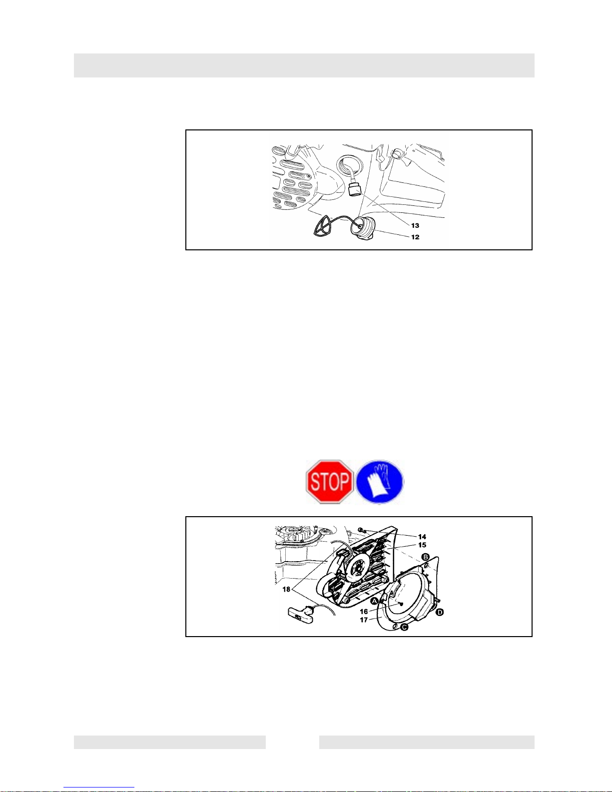
Loosen four screws (14). Remove the fan housing (15).
Unscrew 2 screws (16) and carefully remove air duct (17) from fan
housing.
Note and follow sequence (A-B-C-D).
Remove remainders of old rope (18).
T00963GB 53
Page 56

Maintenance
61
Thread a new 1000mm (40“)long and4,0 mm (0,16“) diameter starter
rope as shown in the drawing (do not forget washer (19) and then tie
knots at both ends.
Pull knot (20) into rope drum (21).
ATTENCION: The knot or, as the case may be, the end of the rope
should not jut out over the surface of the rope drum.
Insert knot (22) into the starter handle (23).
62
Guide therope into the recess (24) on the ropedrum and use the rope
to turn the drum two turns in the direction shown by the arrow.
Holding the rope drum in your left hand, straighten out the twist in the
rope with your right hand, pull the rope tight, and hold.
Release the rope drum. Thedrum‘s springforce willnow wind the rope
around the drum.
Repeatprocedure
the fan housing.
T00963GB 54
three times. The starterhandlemust stand outfrom
Page 57

NOTE: With the rope pulled all the way out, it must still be possible to
turn the pulley another 1/4 turn against the return spring.
ATTENCION! Injury hazard! When you pull out the starter rope
hold the starter handle firmly. It will whip back if the rope drum is
released by accident.
Assemble air duct in reverseorder (seepicture 63).Make sure that the
guide (25) is located inside the seat (26) at the fan housing.
When replaceing fan housing, it may be necessary to pull the starter
rope lightly so that the rope pulley catches.
8.9 Replace the return spring
Maintenance
63
Take off fan housing (see chapter “Starter rope replacement“).
Remove air duct from fan housing (see chapter “Starter rope
replacement“).
Remove retaining ring (1) (see accessories for extemal retaining ring
pliers).
Pull off rope drum (2).
Unscrew screws (3).
Carefully and evenly remove retum spring (4) from spring holder with
screw driver or similar tool. Be extremely careful, as return spring is
pretensed and could jump out of spring holder!
ATTENCION: Danger of bodily harm! Wear safety glasses and
safety gloves under all circumstances!
T00963GB 55
Page 58

Maintenance
Replacement retum springs are delivered inside a housing and
pretensed. CAUTION, the spring can jump out.
A spring that has jumped out can be placed back in the housing by
following the drawing (pay attention to the direction of rotation!).
The new return spring (4) must be lightly greased with multipurpose
grease before proceeding with mounting inside the fan housing. After
greasing insert retum spring (4), press in slightly so that the brackets
(5) snap intothe seats.Screw in screw(3) andonly tighten lightly.Tum
rope drum slightly when placing until it snaps in audibly. Mount
retaining ring. Coil starter rope (see chapter “starter rope
replacement“).
Assemble air duct (see picture 62). If the need arises, pull starter
handle lightly until the starting device grips wehn replacing the fan
housing.
8.10 Cutting arm in inboard/outboard
64
NOTE: The cut-offsaw is deliveredwith the cuttingarm mountedin the
inboard position (1). Forcutting up against obstacles, such as curbs or
walls, the cutting arm can be mounted to one side (outboard) (2). Use
this position only when actually necessary, and afterwards return the
cutting attachment to the inboard position. In this position the cut-off
saw has better balance, is easier to guide, and is not as fatiguing for
the operator.
T00963GB 56
Page 59
8.11 Repositioning the cutting arm
65
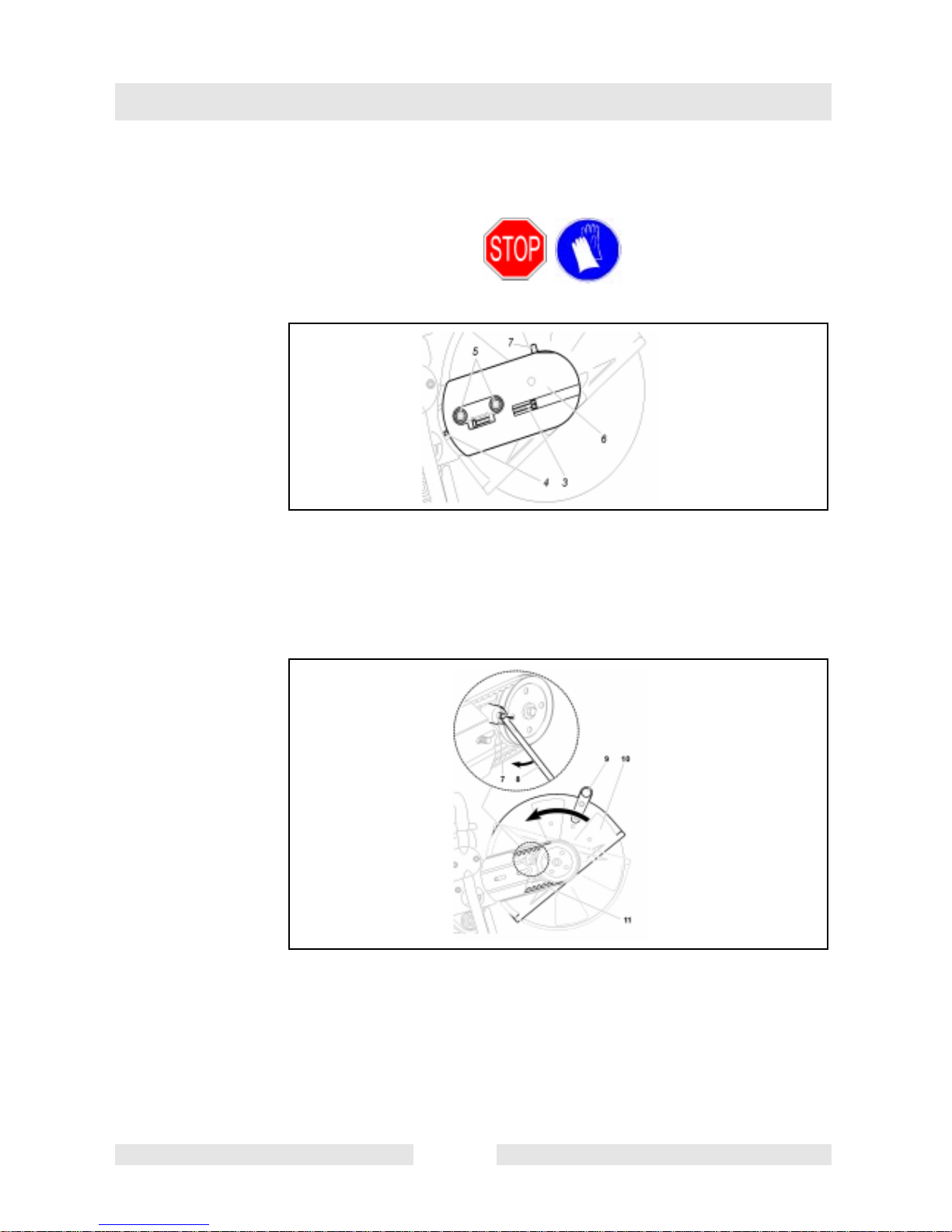
Loosen nuts (5).
Maintenance
Loosen the tighteningscrew(3) (counter-clockwise) untilthe end ofthe
screw (4) is visible in the gap. Unscrew the nuts (5) and remove the
cover (6).
66
Lift out stop bolt (7)with universalwrench (8) as shown in drawing until
protective hood (10) can be turned.
NOTE: The turning stop (65/7) is not active when the stop bolt (7) has
been pulled. The protective hood (10) can thus be turned further than
normally allowed by the turning stop (65/7).
Disengage V-belt and then remove cutting arm.
T00963GB 57
Page 60

Maintenance
67
Press the cutting arm (12) in the side position onto the drive arm
attachment.
Guide the V-belt (13) over the V-belt wheel (14).
68
Put the guard plate (15) on.
Screw on nuts (16) and tighten by hand.
To tighten the V-belt see “Tightening the V-belt / Checking V-belt
tension“.
Tighten the nuts (16) firmly with the combination wrench.
ATTENCION:
When you reposition the cutting attachment, the direction of
rotation of the cutting wheel changes.
Diamond blacks must befilted according to the turning direction!
T00963GB 58
Page 61

8.12 Instructions for periodic maintenance
To ensure long life, prevent damage and ensure the full functioning of
the safety features the following maintenance must be performed
regularly. Warranty claims can be recognized only if this work is
performed regularly and properly. Failure to perform the prescribed
maintenance work can lead to accidents!
Users of the cut-off saw must not perform any maintenance work not
described in this Instruction Manual. All such work must be carried out
by a WACKER service station.
General Entire Power Cut Clean exterior, check for damage. In case of
damage, have repaired by a qualified service
centre immediately
Maintenance
Cutting blade
Clutch
Protection hood Clean, check position
Before
each start
Every day Prefilter Clean. (Replace after 20 running hours)
Every
week
Cutting blade Checkfordamagesandmakesurethecorrect
V-belt Check V-belt tension.
Combination
switch, Safety
locking button,
Throttle lever
Fuel tank plug Check for tightness.
Idle speed Check (cutting blade must not turn on idle).
Fan housing Clean to ensure proper air cooling.
Starter Check for damage.
V-belt Check V-belt tension, inspect for damage and
Air filter cartridge Clean. (Replace after 100 running hours)
Inspect regularly for damage and wear.
cutting blade for the planned aplication has
been filted.
Functional check.
wear.
Every 3
months
T00963GB 59
Spark plug Check and replace if necessary.
Muffler Check tightness of mounting.
Suction head Replace.
Fuel tank Clean.
Bearing
Clutch drum
Clean and regrease.
Page 62

Maintenance
Storage Entire cut-off saw Clean exterior, check for damage. In case of
damage, have repaired by a qualified service
centre immediately
Cutting blade Remove and clean.
Fuel tank Empty and clean.
Carburetor Run empty.
T00963GB 60
Page 63

8.13 Troubleshooting
Malfunction System Observation Cause
Maintenance
Cutting blade
does not start
turning
Cutting blade
turns while
engine idles
Engine does
not start or only
with difficulty
Clutch Engine runs Damage to clutch
Carburetor,
Clutch
Ignition
system
Fuel supply Fuel tank is
Compression system
Cutting blade
turns
Ignition spark Malfunction in fuel supply
No ignition
spark
filled
Inside Cylinder base packing ring
Outside Spark plug does not seal.
Incorrect idle speed, clutch
stuck
system, compression
system, mechanical
malfunction.
Switch on STOP, fault or
short-circuit in the wiring,
plug cap or spark plug
defective.
Choke in wrong position,
carburetor defective,suction
head dirty, fuel line bent or
interrupted.
defective, radial shaft
packings defective, cylinder
or piston rings defective
Mechanical
malfunction
Insufficient
power
Engine does
not start or only
with difficulty
Low
performance
T00963GB 61
Carburetor Fuel tank is
Fuel supply Fuel tank is
Serveral
systems
may be
involved
simultaneously
Starterdoesnot
engage
filled Igntion
spark
filled
Engine is idling Air filter dirty, wrong
Spring in starter broken,
broken parts inside the
engine.
Wrong carburetor
adjustment.
Wrong idling adjustment,
suction head or carburetor
dirty. Tank venting defective,
fuel line interrupted, cable
defective, Stop switch
defective. Starting valve
dirty.
carburetor adjustment,
muffler clogged, exhaust
channel in cylinder clogged.
Page 64
FBTS
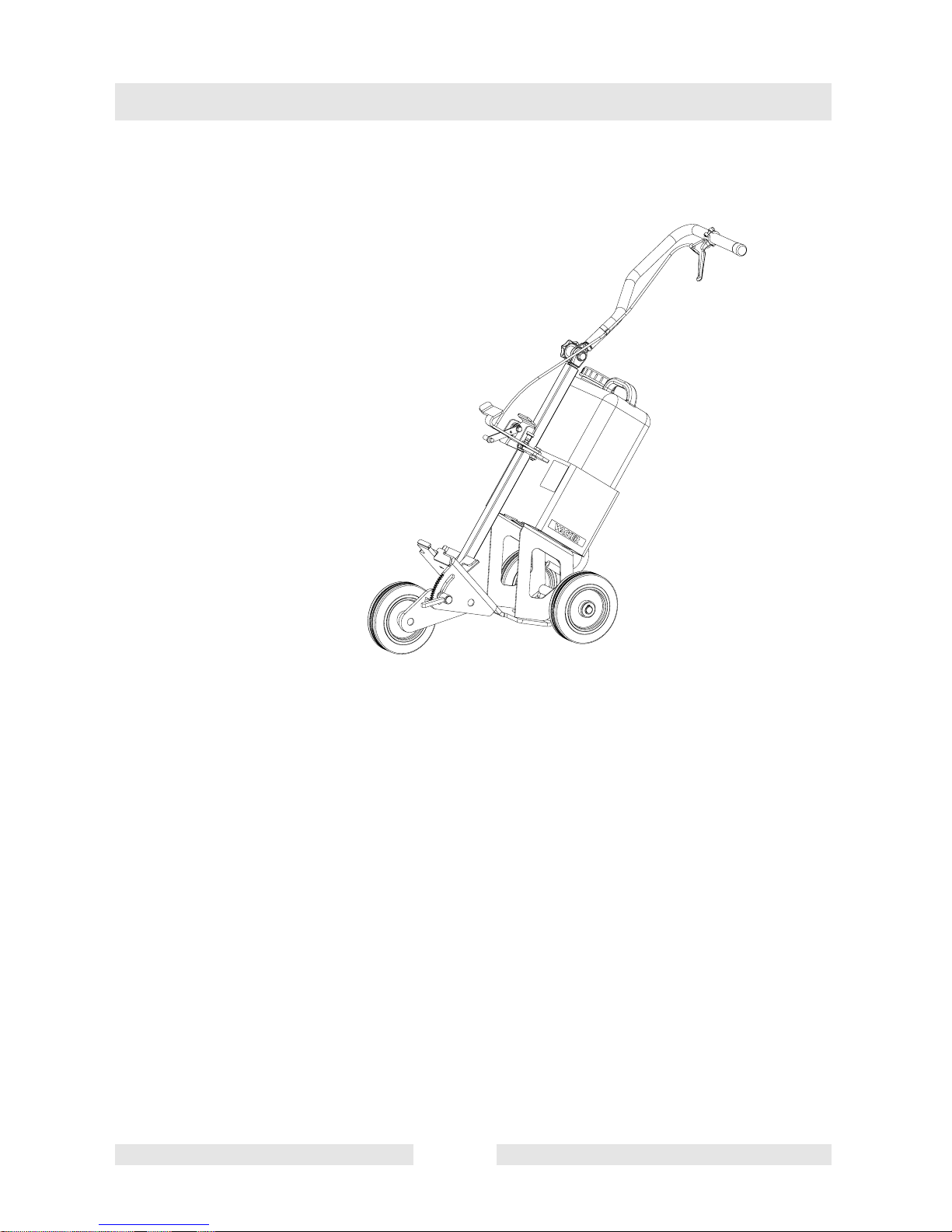
9. FBTS
9.1 Guide cart
The WACKER guide cart makes it much easier to carry out straight
cuts, while simultaneously enabling almost untiring working. It can be
adjusted for theoperator‘s height,and can beoperated withthe cutting
arm mounted in the inboard or outboard position. For easier refuelling
when using the trolley, we recommend adding an angled tank filler
neck.
The guidecart hasbeen equipped with a water tank anda water spray
system; the water will bind the dust during the cutting process and will
also help to cool the cutting disc.
Notches have been added to the area of the clamp lever, thus making
it easier to adjust the cutting depth of the blade. One notch is
equivalent to 10 mm (0,4“) cutting depth.
T00964GB 62
Page 65

9.2 Safety precautions
9.2.1 The mounting brackets for the cut-off saw must be cleaned before
placing the BTS into the guide cart.
9.2.2 The stopbolt must be correctly engaged to avoid a possible detaching
of the cut-off sawduring applications.
9.2.3 Be careful to verify that both the clamp lever for the cutting depth
setting and the star-shaped knob for the handle height setting are
tightly screwed down during cutting applications.
9.2.4 The guide cart should be cleaned with water after each use to avoid
possible malfunctions.
9.2.5 Park the equipmentonan even, horizontalsurface during workbreaks,
storage or transport. Also make sure that the equipment has been
secured against tipping over or rolling away.
FBTS
9.2.6 Push the throttle lever to the idle position (forwards) immediately after
ending the cutting process.
T00964GB 63
Page 66

Labels
10. Labels
1 Fuel to oil ratio
2 Wacker Logo
3 Type
4 Cover safety
5 Protective hoad safety
SK00658GB 64
Page 67

EC - Confornity Certificate
Wacker Construction Equipment AG , Preußenstraße 41, 80809 München
hereby certify that the construction equipment specified hereunder:
1. Category:
Portable gasoline cut-off saw
2. Type:
BTS 930L3 / BTS 935L3 BTS 1030L3 / BTS 1035L3
3. Equipment item number:
0008340 ... / 0008341 ...
0008987 ... / 0008988 ...
0008339 ... / 0007975 ... / 0008912 ...
0008989 ... / 0008990 ...
4. absolute installed power:
3,2 kW 4,2 kW
has been evaluated in conformity with Directive 2000/14/EC:
Conformity assessment
procedure
Annex V 109 dB(A) 110 dB(A) 111 dB(A)
Measured sound power level Guaranteed sound
power level
BTS 930/935L3 BTS 1030/1035L3
and has been manufactured in accordance with the following directives:
* 2000/14/EG
* 89/336/EG
* 98/37/EG
File certificate carefully
C0003106GB
Dr. Sick
Board of Directors
Page 68

Page 69

DIN EN ISO 9001 CERTIFICATE
Page 70

Page 71

Page 72

 Loading...