

Page 1

www.wackergroup.com
Cut-Off Saws
BTS 930-8340
BTS 935-8341
BTS 1030-8339
BTS 1035-7975
REPAIR MANUAL
0118754en 005
0903
0118754EN
Page 2

Page 3

BTS Repair Table of Contents
wc_br0118754enTOC.fm 1
1. Technical Data 5
1.1 BTS 930 / BTS 935 / BTS 1030 / BTS 1035 ........................................ 5
2. Special Tools 6
3. Clutch 7
3.1 Dismantling the clutch/drum ................................................................. 7
3.2 Mounting muffler and heat plate ........................................................... 8
3.3 Repairing the clutch ........................................... ..... ..... .... ..................... 8
3.4 Mounting the clutch/drum ..................................................................... 9
4. Ignition System 10
4.1 Checking the spark plug ..................................................................... 10
4.2 Replacing the plug connector ............................................................. 11
4.3 Removing/assembling the ignition / short circuit cable ....................... 12
4.4 Removing/checking/mounting the ignition armature .......................... 14
4.5 Removing/mounting the flywheel ....................................................... 15
5. Starting System 16
5.1 Removing/mounting the starter / return spring ................................... 16
5.2 Pretensioning/checking the return spring ........................................... 17
5.3 Replacing the starter ratchet .............................................................. 17
6. Carburetor 18
6.1 Setting the carburetor ......................................................................... 18
6.2 Removing the carburetor and intake hose ......................................... 19
6.3 Carburetor - dismantling/testing the control side ................................20
6.4 Carburetor - dismantling/testing the pump side ..................................21
6.5 Carburetor - Cleaning the fuel filter ..... ..... ..... ..................................... 21
Page 4

Table of Contents BTS Repair
wc_br0118754enTOC.fm 2
7. Hood System / Air Filter / Winter Operation 22
7.1 Air Filter ...............................................................................................22
7.2 Winter Operation .................................................................................23
8. Front Handle / Vibration Absorbers 24
8.1 Removing and replacing the bracket handle .......................................24
8.2 Replacing the vibration absorbers .......................................................24
9. Fuel Tank / Fuel Filter 25
9.1 Removing/inserting the ventilation valve .............................................25
9.2 Replacing the throttle lever mechanism ..............................................25
9.3 Replacing the fuel pipe ........................................................................26
9.4 Testing the fuel filter ............................................................................26
10. Cylinder / Piston / Decompression Valve 27
10.1 Dismantling/mounting the cylinder / piston ..........................................27
10.2 Testing the decompression valve ........................................................28
11. Crankcase / Crankshaft 29
11.1 Crankcase / crankshaft ........................................................................29
12. Cutting Attachment 30
12.1 Replacing the pressure disc ................................................................30
12.2 Removing / mounting the V-belt pulley ................................................30
12.3 Replacing the drive axle ......................................................................31
12.4 Removing the complete pressure ring .................................................31
12.5 Cutter guard holding attachments .......................................................31
12.6 Replacing the guard stop ....................................................................32
12.7 Replacing the fixing screw ...................................................................32
Page 5

BTS Repair Table of Contents
wc_br0118754enTOC.fm 3
12.8 Removing / mounting the cutting device bearings .............................. 33
12.9 Adjusting the cutter guard holding attachment ................................... 34
12.10 Tensioning the V-belt ......................................................................... 34
13. Torques 35
13.1 BTS 930 / BTS 935 / BTS 1030 / BTS 1035 ...................................... 35
Page 6

Table of Contents BTS Repair
wc_br0118754enTOC.fm 4
Page 7

BTS Repair Technical Data
wc_td000126gb.fm 5
1. Technical Data
1.1 BTS 930 / BTS 935 / BTS 1030 / BTS 1035
Item No.
BTS 930
0008340
BTS 935
0008341
BTS 1030
0008339
BTS 1035
0007975
Saw
Displacement
cm³ (in³)
62 73
Bore
mm (in.)
47 (1.8) 50 (2.0)
Stroke
mm (in.)
37 (1.5) 37 (1.5)
Max. Power
kW (Hp)
3.3 (4.4) 4.2 (5.5)
Max. Torque
Nm
4.0 5.0
Idling Speed
rpm
2500 2500
Clutch engagement speed
rpm
3800 3800
Engine speed limitation
rpm
9350 9350
Max. spindle speed
rpm
4300 4300
Carburetor (diaphragm)
type
Tillotson HS-273 A
Ignition system
(with speed limitatio n)
type
electronic
Spark plug
type
NGK BPMR 7A / BOSCH WSR 6F /
CHAMPION RCJ 6Y
Electrode gap
mm (in.)
0.5 (0.020)
Fuel consumption
1)
l/h (qts./h)
1.85 (2) 2.36 (2.5)
Specific consumpti o n
1)
g/kWh
500 500
Fuel tank capacity
l (qts.)
1.1 (1.2) 1.1 (1.2)
Mixture ratio (fuel/two-stroke oil) 50:1 50:1
Cutting disc for 80 m/sec. 2)
(DSA approved)
mm
3)
300/20.0/5 350/24.5/5 300/20.0/5 350/24.5/5
Arbor diameter
mm
20.0 25.4 20.0 25.4
V-belt AVX 838 LA AVX 838 LA
Overall weight
4)
kg (lbs.)
9.7 (21) 9.9 (22) 9.8 (21) 10 (22)
1) At max. load per ISO 8893
2) Circumferance speed at max. engine speed
3) Outside diameter / arbor hole / thickness
4) tanks empty, without cutting disc.
Page 8

Special Tools BTS Repair
wc_tx000326gb.fm 6
2. Special Tools
Ref. Part Number Description
1. 0068900 Puller for flywheel
2. 0117570 Puller for oil seals
3. 0117573 Puller for ball bearing count er support
4. 0117569 Puller for ball bearing inside puller
5. 0117575 Set of piston ring tenson belt
6. 0117571 Piston stop wedge
7. 0117574 Mounting tool for clutch hub
3
5
6
1
2
7
wc_gr001381
Page 9
BTS Repair Clutch
wc_tx000298gb.fm 7
3. Clutch
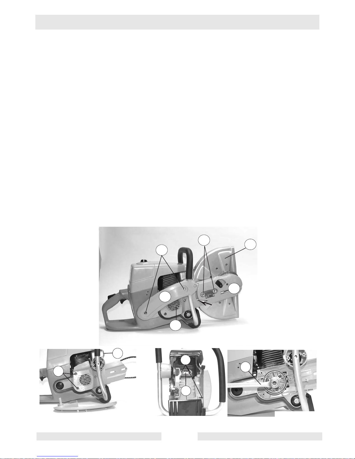
3.1 Dismantling the clutch/drum
See Graphic: wc_gr001384 and wc_gr001385
3.1.1 To dismantle the clutch and drum, remove the cutting device (1), strut
(2) and V-belt cover (3).
3.1.2 To remove the cutting device, loosen the fixing screws (4). Remove
screw (5) to the point whe re the end of the screw projects from the
cover (arrow).
3.1.3 The side strut is fixed with 3 screws (7) to the tank and the collector for
the right upper damper device.
3.1.4 The cover for the V-belt is fixed to the crankcase with 3 screws (8).
3.1.5 To remove the clutch and drum, the piston must be blocked. To do this,
unscrew the 3 screws (9) fixing the muffler (10) and insert the piston
stop wedge (0117571) into the exhaust port of the cylinder (11).
3.1.6 Unscrew the clutch with the special tool (0117574) and a 19mm
wrench (a).
Note: left-handed thread.
7
4
2
1
3
5
wc_gr001384
9
11
a
8
10
wc_gr001385
Page 10
Clutch BTS Repair
wc_tx000298gb.fm 8
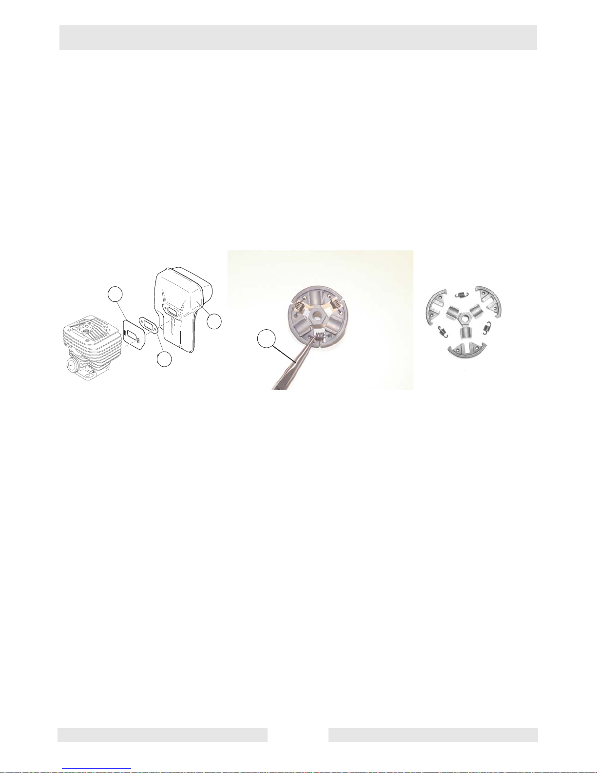
3.2 Mounting muffler and heat plate
See Graphic: wc_gr001 38 6
When mounting the muffler (10) ensure that the heat plate (12) is
installed correctly.
Note: The heat plate goes directly onto the cylinder, then the gasket
(13) and muffler.
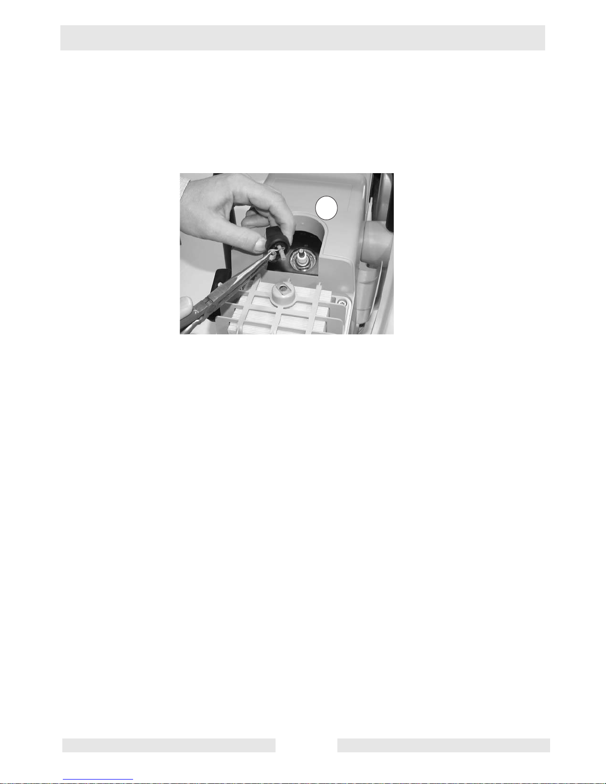
3.3 Repairing the clutch
See Graphic: wc_gr001 38 6
3.3.1 The tension springs of the clutch can be removed/ replaced with
pointed pliers (b). If spar es are requir ed, the 3 tension springs are onl y
available as individual parts.
3.3.2 The tension spring s shou ld on ly be re plac ed as a set if repl aceme nt is
required.
3.3.3 If the hub / flyweight is defective, the complete clutch must be
replaced.
wc_gr001386
b
Page 11
BTS Repair Clutch
wc_tx000298gb.fm 9
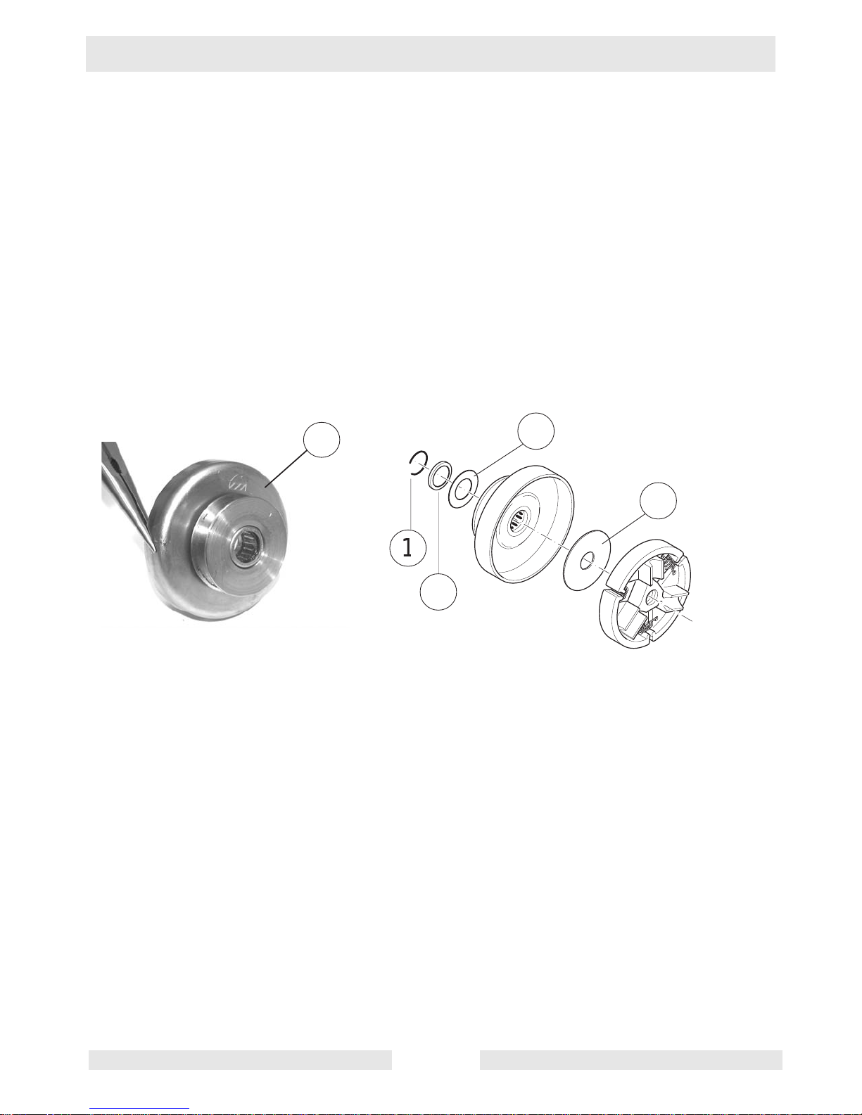
3.4 Mounting the clutch/drum
See Graphic : wc_gr001387
3.4.1 Before installing the clutch dr um, the ne edle bear ing that is pressed i n
must be greased. (Alvania #2)
3.4.2 When mounting the drum and the clutch, be careful to mount the
washers in the right order.
• (1) Ring (sits in the groove of the crankshaft)
• (2) End collar (with recess towards ring)
• (3) Guide washer
• (4) Clutch guide washer, before assembly.
Press into the support on the back of the clutch hub.
wc_gr001387
a
Page 12
Ignition System BTS Repair
wc_tx000299gb.fm 10
4. Ignition System
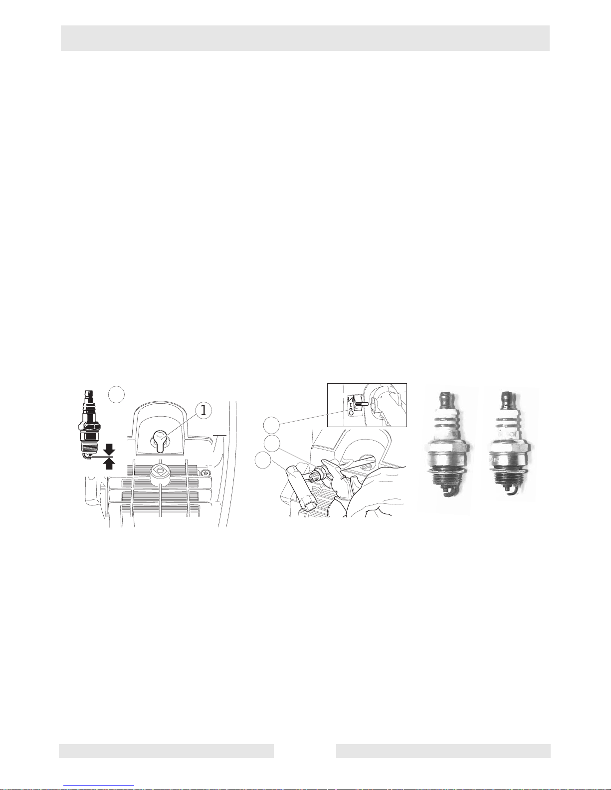
4.1 Checking the spark plug
See Graphic: wc_gr001 38 8
4.1.1 Remove filter hood.
4.1.2 Pull spark plug socket (1) off the spark plug and remove spark plug (2).
4.1.3 Connect spark plug (2) with plug socket and h old to ground (3). Pull out
starter cable. If no spark is produced, repeat procedure with new spark
plug.
Note: Switch (4) must be in position “I”.
4.1.4 Combustion and mo tor performance w ill be improved if the spark plugs
function properly. Dirty or faulty spark plugs should therefore be
cleaned or replaced.
• The spark plug pictured (a) has serious oil carbon deposits.
Clean or replace spark plug.
• This spark plug (b) is showing signs of wear (burning off) on the
middle electrode. Spark plug must be replaced.
S
T
O
P
0,5 mm
wc_gr001388
b
a
Page 13
BTS Repair Ignition System
wc_tx000299gb.fm 11
4.2 Replacing the plug connector
See Graphic : wc_gr001389
Hold the plug connector spring using pointed pliers and push the
rubber cap backwards over the ignition cable.
Note: Grease the ignition cable slightly beforehand.
a
wc_gr001389
Page 14

Ignition System BTS Repair
wc_tx000299gb.fm 12
4.3 Removing/assembling the ignition / short circuit cable
See Graphic: wc_gr001 39 0, wc_ g0 01 391, wc_gr001392 and wc_gr 001 393
Removing
4.3.1 Unscrew the starter device that is fixed with 4 screws (a).
4.3.2 Unscrew filter hood.
4.3.3 Remove ignition and short cir cuit cab le from the guide (1) of the hood .
4.3.4 Remove hood - to do this, unscrew the 3 screws (2).
4.3.5 The screw (2a) also holds the gr ounding wire.
4.3.6 Unscrew ignition from the ignition armature.
4.3.7 Loosen short circuit cable from the socket connection (b).
4.3.8 Loosen the hose clamp (3) of the intake hose.
4.3.9 Pull the suction hose (4) off the cylinder.
4.3.10 Loosen the locking device of the intake elbow from the tank housing.
To do this, push both levers inwards (arrows) and lift the intake elbow
slightly.
4.3.11 Push throttle control rod towards the cylinder using pointed pliers,
pulling upwards out of the guide of the gas grip (c).
4.3.12 Remove intake elbow with carburetor and choke shaft from the tank
housing (d).
4.3.13 Pull short circuit cable (5) from its place in the choke shaft (6).
4.3.14 Loosen grounding wire (7) from the socket connection of the contact
spring.
wc_gr001390
a
1
2
2a
3
4
b
wc_gr001391
Page 15

BTS Repair Ignition System
wc_tx000299gb.fm 13
Assembling
4.3.1 When mounting the short circuit cable, make sure that the connection
between the connector lug of th e short circuit cable and the contact
spring is in order (a).
4.3.2 Twist ignition cable into the ignition armature.
Note: To prevent moisture leaking in, fi ll protective cap (4) with silicone
before replacing.
4.3.3 As a safety measure, lay the short circuit cable in the brackets
underneath the ignition cable du ring assembly (b).
7
8
5
6
c
d
wc_gr001392
wc_gr001393
b
4
a
Page 16

Ignition System BTS Repair
wc_tx000299gb.fm 14
4.4 Removing/checking/mounting the ignition armature
See Graphic: wc_gr001 39 4
Removing
4.4.1 Unscrew starting device.
4.4.2 Remove the two screws (1) of the ignition armature. Clip off ignition
and short circuit cable.
Checking
4.4.1 In the event of a fault, first check the ignition ground connection.
To do this, loosen and then tighten the screws (1) a few times, then
check ignition once again.
Mounting
4.4.1 Connect ignition and short circuit cable.
4.4.2 Position with 0.012" – 0.016" (0.3 mm – 0.4 mm) (a) between ignition
device and magnet on the flywheel.
4.4.3 Press ignition device firmly whilst at the same time tightening the
screws evenly.
1
a
b
wc_gr001394
Page 17

BTS Repair Ignition System
wc_tx000299gb.fm 15
4.5 Removing/mounting the flywheel
See Graphic : wc_gr001395
Removing
4.5.1 Block the piston using the piston stop wedge.
4.5.2 Unscrew bolt (2) and remove washer (3).
4.5.3 Rem ove flywheel with pulling device 0037576 (a).
CAUTION: To avoid damage to the crankshaft, always use the
protective cap included with the pu lling device.
Mounting
4.5.1 Before mounting the flywheel, the cone seat and the crankshaft (4)
must be cleaned.
4.5.2 The flywheel is tightened with a torque of 23 ft.lbs. (30 Nm).
wc_gr001395
2
3
a
4
Page 18

Starting System BTS Repair
wc_tx000300gb.fm 16
5. Starting System
5.1 Removing/mounting the starter / return spring
See Graphic: wc_gr001 39 6
Removing the starter
5.1.1 Remove air duct (1).
5.1.2 Relieve the tension on the return spring by pulling out the starter cable
(2) slightly.
5.1.3 Hold cable drum and remove cable from rope drum. Let drum spool
back slowly.
Removing the return spring
5.1.1 To remove the return spring, remove the circlip ring (3); the return
spring (4) is in a cartridge which is fixed to the fan housing with three
screws (5).
Note: Lightly grea se new spring.
Mounting the return spring /starter cable
5.1.1 Thread cable through, kno tting (6) into the cab le dr um and kno tting (7)
into the starter grip (8).
5.1.2 The washer (9) is mounted between the starter grip and the knot.
Note: Melt cable ends.
2
1
wc_gr00139
6
Page 19

BTS Repair Starting System
wc_tx000300gb.fm 17
5.2 Pretensioning/checking the return spring
See Graphic : wc_gr001367
Pretensioning the return spring
Wrap the starter cable as far as p ossibl e aroun d th e dr um . Hol d cable
tight and turn the drum with the cable 2-3 times to pretension (a).
Checking the return spring
When the starter cable is fully extend ed, the rope drum m ust still turn
at least half a turn (b).
5.3 Replacing the starter ratchet
See Graphic : wc_gr001367
5.3.1 Knock out the bolts with a punch (c).
5.3.2 To assemble, push the punch in so far that there is only 0.06"–0.07"
(0.15 mm–0.2 mm) between the ratchet and the bolt (10).
22
10
c
b
a
wc_gr001397
Page 20

Carburetor BTS Repair
wc_tx000301gb.fm 18
6. Carburetor
6.1 Setting the carburetor
See Graphic: wc_gr001 39 8
Set Idling Nozzle “L” at 1 3/8 (-1/16) turn
For the basic setting, turn in the idling nozzle “L” carefully as far as it
will go. Then back off “L” nozzle 1 3/8 turn.
For fine tuning, the “L” nozzle only needs to be changed by max.
- 1/16 of a turn.
“S” Idling Screw
When during idling the engine speed is too high (moving of cutting
disc) or too low (engine stalls), correct the the settin g of idling screw
“S” (speed) accordingly.
“H” Main Nozzle
BTS 930/935: The main nozzle “H ” is set at the factor y to 6/8 of a turn.
BTS 1030/1035: The main nozzle “H” is set at the factory to 7/8 of a
turn except for machines built in 2002 (S/Ns 5289575 to 5355979)
which were set at the factory to 6/8 of a turn.
S
H
L
wc_gr001398
Page 21

BTS Repair Carburetor
wc_tx000301gb.fm 19
6.2 Removing the carburetor and intake hose
See Graphic : wc_gr001399
Removing the carburetor
6.2.1 Remove intake elbow with carburetor.
6.2.2 Remove choke shaft (1), choke rod (2) and throttle control rod (3).
Unscrew the two fixing screws (4).
6.2.3 Remove the carbure tor from the intake elbow.
6.2.4 The seal (5) must not block the bore (6) for ventilating th e con tr ol si de
of the carburetor (compensation system).
Intake hose
6.2.1 Pull the intake ho se (7) out of the intake elbow and check for damage.
6.2.2 Replace the insert (8) in the intake hose again before assembling the
carburetor.
wc_gr
001399
6
5
3
2
4
1
Page 22

Carburetor BTS Repair
wc_tx000301gb.fm 20
6.3 Carburetor - dismantling/testing the control side
See Graphic: wc_gr001 40 0
Dismantling the control side
6.3.1 Unscrew cover (1). Carefully remove the seal (2) and diaphragm (3)
from the control lever (4).
6.3.2 Remove control lever, spring (5) and inlet needle (6) from the
carburetor.
Testing the control membrane
6.3.1 After removing the control diaphragm, it must remain flat. The rim
around the stiffe ning plate (7) must be even. Faulty diaphragm must be
replaced immediately.
Testing the control unit
6.3.1 After removing the contr ol diaphragm, remove the int ake pin with valve
rocker and spring.
Note: If there is visible wear (arrows), the control unit must be
replaced.
wc_gr001400
Page 23

BTS Repair Carburetor
wc_tx000301gb.fm 21
6.4 Carburetor - dismantling/testing the pump side
See Graphic : wc_gr001401
Dismantling the pump side
Unscrew cover (8). Remove seal (9) and diaphragm (10) from the
carburetor.
Testing the pump membrane
The two valve flaps (arrow) must re st flat on the body of the carburetor.
Damaged diaphragms must be replaced immediately, as starting and
running problems may otherwise occur.
6.5 Carburetor - Cleaning the fuel filter
See Graphic : wc_gr001401
The fuel filter (11) may be carefully remove d fr om th e carbu r eto r b ody
for cleaning with a pointed object. After cleaning replace the fuel filter
with a pin.
wc_gr001401
a
a
Page 24

Hood System / Air Filter / Winter Operation BTS Repair
wc_tx000302gb.fm 22
7. Hood System / Air Filter / Winter Operation
7.1 Air Filter
See Graphic: wc_gr001 40 2
Only well-maintained filters will guarantee efficient engine
performance and a long working life. Damaged or worn filters must
therefore be replaced.
Removing the air filter
7.1.1 Remover filter hood (5), unscrew cover hood (4).
7.1.2 Filter system consists of the pre-filter (1), the paper cartridge (2) and
the inside filter (3).
Cleaning the pre-filter
7.1.1 Clean the pre-filter (a) in lukewarm soapy water using normal liquid
detergent. Dry before replacing.
Note: If the inserts are extremely dusty, the pre-filter may need to be
oiled slightly.
Cleaning the paper cartridge
7.1.1 Unscrew the 4 screws on the cover hood (4). To clean, fan the paper
cartridge (b) out slightly and tap gently.
Note: Never wash the paper cartridge to clean it.
Clean inside filter
7.1.1 The inside filter (c) should also be washed out in lukewarm soapy
water.
b
a
wc_gr001402
Page 25

BTS Repair Hood System / Air Filter / Winter
wc_tx000302gb.fm 23
7.2 Winter Operation
See Graphic : wc_gr001403
Temperatures below zero may cause the filter/ carburetor to freeze.
Remove summer-winter insert from summer mode (6) and insert in
winter mode (7) as shown.
Return to summer mode when temperature is above 32°F (0°C).
wc_gr00140
3
c
d
Page 26

Front Handle / Vibration Absorbers BTS Repair
wc_tx000303gb.fm 24
8. Front Handle / Vibration Absorbers
8.1 Removing and replacing the bracket handle
See Graphic: wc_gr001 40 4
To dismantle the front handle, the strut (1) with 3 screws and the foot
(2) with 2 screws must be unscrewed.
8.2 Replacing the vibration absorbers
See Graphic: wc_gr001 40 5
The system consists of 4 vibration absorbers, 3 of which are on the
clutch side.
8.2.1 To dismantle them, the front handle, filter system and tank must be
removed.
8.2.2 The fourth vibration absorber is on the flywheel side. To dismantle it,
the starter device must be removed.
8.2.3 The vibration absorbers are slotted into the housing. Mount the
sleeves (3+4) with the collars inwards.
8.2.4 Lightly grease vibration absorbers.
1
2
wc_gr001404
b
3
4
a
wc_gr001405
Page 27

BTS Repair Fuel Tank / Fuel Filter
wc_tx000304gb.fm 25
9. Fuel Tank / Fuel Filter
9.1 Removing/inserting the ventilation valve
See Graphic : wc_gr001406
Removing
Push the ventilation valve with a pin into the tank (arrow) and remove
with pointed pliers throug h the filler opening (a).
Inserting
Press the new ventilation valve with a pin into the housing until the
white sinter plastic projects about 2–3 mm beyond the tank (b).
9.2 Replacing the throttle lever mechanism
See Graphic : wc_gr001406
Push the two cylindrical pins (1) out of the handle dish (2).
The throttle lever (3), spring (4) and throttle lock (5) may now be
removed.
The throttle lock pin (6) for half throttle can also now be replaced.
2-3mm
(.080”-0.12”)
2
b
a
wc_gr001406
Page 28

Fuel Tank / Fuel Filter BTS Repair
wc_tx000304gb.fm 26
9.3 Replacing the fuel pipe
See Graphic: wc_gr001 40 7
Unscrew tank cap, remove suction head (7) from tank and pull off the
suction pipe (8). Pull suction pipe upwards out of the tank.
9.4 Testing the fuel filter
See Graphic: wc_gr001 40 7
Dirty felt filters or filters which have become hardened/blocked with
fuel will lead to leanin g of the fu el/air mix and w ill damag e the e ngine
(c).
Note: The fuel filter mus t therefore be checked/replaced regularly.
A fingernail test ca n b e u sed to ch eck wh ether the filter is blocke d (d) .
• Easy to push in = filter OK
• Cannot be pushed in = replace
wc_gr001407
c
d
Page 29

BTS Repair Cylinder / Piston / Decompression Valve
wc_tx000305gb.fm 27
10. Cylinder / Piston / Decompression Valve
10.1 Dismantling/mounting the cylinder / piston
See Graphic: wc_gr001408 and wc_gr001409
Dismantling the cylinder
10.1.1 To disman tle t he cylin der, u nscre w the 4 scr ews (1) from the cylinder
foot.
10.1.2 Pull cylinder off crankcase and piston.
Dismantling the cylinder - piston
10.1.1 Remove piston pin securing ring (2) from the an nul a r slo t i n the pi st on
using pointed pliers. Push piston pin out.
Note: During assembly, make sure the securing ring clicks completely
into the groove.
Mounting the cylinder - piston
10.1.1 Wh en mounting pist on, the arrow on top of the piston has to point in
direction of muff ler.
Note: Before assembling the piston ensure that the cylinder base
gasket (3) is fitted correctly.
Mounting the cylinder
10.1.1 Position the fork (4) of the piston ring tight ening device (0117575) onto
the crankcase. Press the piston ring together using the ring clamp.
When positioning the cylinder, push the ring clamp away downwards.
10.1.2 After positioning the cylinder, tighten fixing screw with a torque of 10
ft.lbs. (14 Nm) (b).
1
1
2
wc_gr001408
3
Page 30

Cylinder / Piston / Decompression Valve BTS Repair
wc_tx000305gb.fm 28
10.2 Testing the decompression valve
See Graphic: wc_gr001 40 9
Unscrew valve and check valve seating (a) and the hole in the cyli nder
for dirt.
Replace valve if dirty. Clean hole carefully.
4
b
a
wc_gr001409
Page 31

BTS Repair Crankcase / Crankshaft
wc_tx000306gb.fm 29
11. Crankcase / Crankshaft
11.1 Crankcase / crankshaft
See Graphic: wc_gr001410 and wc_gr001411
Complete crankcase
The complete crankcase is divided into the crankcase magnet side (2)
“MS”, and the crankcase clutch side (1) “KS”.
Removing the crankcase “MS”
To dismantle the magnet side (MS), unscrew the 4 fixing screws (3)
and the left lower screw (4).
Dismantling the crankcase
After removing the 5 fixing screws, separate the crankca se carefully by
tapping with a plastic hammer (a).
Replacing the crankshaft / bearing
First push bearing onto the crankshaft, then insert crankshaft with
bearing (5) into the case, “KS”. Place gasket on centering pins.
Note: To dismantle or assemble the bearings, heat the crankcase to
212–248°F (100–120°C ) .
Mounting the bearing / crankcase
Heat the crankcase “MS” and fit bearing into the case (b).
Note: The bearing faces with its open side to the crankshaft. Before
installation moisten the outside of the bearing with “Loctite 601”.
Mounting the crankcase
Tighten the 5 fixing screws with a torque of 7 ft.lbs. (10 Nm) (c).
1
2
4
3
a
wc_gr001410
5
b
c
wc_gr001411
Page 32

Cutting Attachment BTS Repair
wc_tx000307gb.fm 30
12. Cutting Attachment
12.1 Replacing the pressure disc
See Graphic: wc_gr001 41 2
12.1.1 Undo screw (1) and remove pressure disc.
Note: W ith the 25.4 mm (1") axle, the inner flange is located behi nd the
recess of the axle (2).
12.1.2 Remove axle and flange together.
12.2 Removing / mounting the V-belt pulley
See Graphic: wc_gr001 41 2
Removing
Block the V-belt pulley (3). To do this, push a pin throu gh the ho le (4)
in the V-belt pulley into the housing. Remove screw (5).
Mounting
When mounting the pulley, make sure that the shim 0108152 (6) is
mounted betwee n the V-belt pulley and the ball bearing .
Note: Th e V-belt pulley is on ly fixed in place when the cutting disk is
mounted.
wc_gr001412
1
2
3
4
5
6
Page 33

BTS Repair Cutting Attachment
wc_tx000307gb.fm 31
12.3 Replacing the drive axle
See Graphic : wc_gr001413
To remove the axle (7), the pressure disk (8) and the V-belt pulley must
be dismantled.
Note: When mo unting th e inner flang e disk, make su re that th e spacer
sleeve (9) 0108151 is mounted.
12.4 Removing the complete pressure ring
See Graphic : wc_gr001413
Unscrew the 3 screws with springs (10), the housing (14) and the
pressure ring (11).
Note: The screws (10) have to be fitted at angles of 120° and are
tightened to 7.3 ft.lbs. (10 Nm).
12.5 Cutter guard holding attachments
See Graphic : wc_gr001413
When mounting, place as follows:
Inside Outside
11 Pressure ring 14 Housing
12 Teflon ring 12 Teflon ring
13 Rubber part 16 Locking plate
- 15 Rubber part
10
14
wc_gr001413
Page 34

Cutting Attachment BTS Repair
wc_tx000307gb.fm 32
12.6 Replacing the guard stop
See Graphic: wc_gr001 41 4
Knock the shaft (1) with a pin out of the handle (2).
To assemble, push the ne w handle onto the shaf t until the shaft is flu sh
with the outside edge of the handle.
12.7 Replacing the fixing screw
See Graphic: wc_gr001 41 4
Push the screws (3) out of the housing.
Before inserting, wet the stop area (arrow) on the screws with “Loctite
609”.
wc_gr001414
Page 35

BTS Repair Cutting Attachment
wc_tx000307gb.fm 33
12.8 Remo ving / mounting the cutting device bearings
See Graphic : wc_gr001415
Removing
12.8.1 Warm housing, remove ball bearings, spacer sleeve and snap rings
from the housing.
Mounting
12.8.1 Hea t housing up to approx. 212°F (100°C).
12.8.2 Mount external snap ring (4).
12.8.3 Push ball bearing (5) up against the ring.
12.8.4 Insert middle ring (6) and spacer sleeve (7), then push second ball
bearing up to ring.
wc_gr001415
a
4
5
7
8
Page 36

Cutting Attachment BTS Repair
wc_tx000307gb.fm 34
12.9 Adjusting the cutter guard holding attachment
See Graphic: wc_gr001 41 6
If the guard is subjected to high stresses, the holding attachment and
the guard may no longer be aligned (arrows).
For correction, loosen screws (8) and adjust holding attachment.
12.10 Tensioning the V-belt
See Graphic: wc_gr001 41 6
12.10.1 After mounting the cutting device, tighten the nuts (9) by hand.
12.10.2 Turn the screw (10) until the squar e nut (11) is aligned with the marking
(12) on the hood.
12.10.3 Tighten the nuts (9) to 14 ft.lbs. (20 Nm).
8
wc_gr00141
6
Page 37

BTS Repair Torques
wc_tx000327gb.fm 35
13. Torques
13.1 BTS 930 / BTS 935 / BTS 1030 / BTS 1035
Assembly set Nm (ft.lbs.)
Muffler 10 + 1 (7) **
Crankcase 10 + 1 (7) **
Cylinder 14 + 1 (10) **
Ignition coil 6 + 1 (53 in.lbs.) **
Fro nt ha ndl e 7 ± 0.5 (60 in.lbs.)
Rubber mounts 7 ± 0.5 (60 in.lbs.)
Carburetor 1.5 ± 0.5 (13 in.lbs.)
Clutch 55 ± 0.2 (40)
Flywheel 30 ± 2.5 (22)
Spark plug 25 ± 2.5 (19)
V-belt pulley 25 + 5 (19)
** Screws with locking serration
Page 38

Torques BTS Repair
wc_tx000327gb.fm 36
Page 39

Threadlockers and Sealants
Threadlockers and Sealants
Threadlocking adhesives and sealants are specified throughout this
manual by a notation of “S” plus a number (S#) and should be used
where indicated. Threadlocking compounds normally break down at
temperatures above 175°C (350°F). If a screw or bolt is hard to
remove, heat it using a small propane torch to break down the sealant.
When applying sealant s, follow instru ctions on conta iner. The sealant s
listed below are recommended for use on Wacker equipment.
TYPE
( ) = Europe
COLOR USAGE
PART NO. SIZE
Loctite 222
Hernon 420
Omnifit 1150 (50M)
Purple Low strength, for locking threads smaller than 6 mm
(1/4").
Hand tool removable.
Temp. range, -54 to 149 ° C (-65 to 300 ° F)
73287 - 10 ml
Hernon 423
Omnifit 1350 (100M)
Blue Medium strength, for locking threads larger than
6 mm (1/4").
Hand tool removable.
Temp. range, -54 to 149 ° C (-65 to 300 ° F)
29311 - .5 ml
17380 - 50 ml
Loctite 271/277
Hernon 427
Omnifit 1550 (220M)
Red High strength, for all threads up to 25 mm (1”).
Heat parts before disassembly.
Temp. range, -54 to 149 ° C (-65 to 300 ° F)
29312 - .5 ml
26685 - 10 ml
73285 - 50 ml
Loctite 290
Hernon 431
Omnifit 1710 (230LL)
Green Medium to high strength, for locking preassembled
threads and for sealing weld porosity (wicking).
Gaps up to 0.13 mm (0.005")
Temp. range, -54 to 149 ° C (-65 to 300 ° F)
28824 - .5 ml
25316 - 10 ml
Loctite 609
Hernon 822
Omnifit 1730 (230L)
Green Medium strength retaining compound for slip or press
fit of shafts, bearings, gears, pulleys, etc.
Gaps up to 0.13 mm (0.005")
Temp. range, -54 to 149 ° C (-65 to 300 ° F)
29314 - .5 ml
Loctite 545
Hernon 947
Omnifit 1150 (50M)
Brown Hydraulic sealant
Temp. range, -54 to 149 ° C (-65 to 300 ° F)
79356 - 50 ml
Loctite 592
Hernon 920
Omnifit 790
White Pipe sealant with Teflon for moderate pressures.
Temp. range, -54 to 149 ° C (-65 to 300 ° F)
26695 - 6 ml
73289 - 50 ml
Loctite 515
Hernon 910
Omnifit 10
Purple Form-in-place gasket for flexible joints.
Fills gaps up to 1.3 mm (0.05")
Temp. range, -54 to 149 ° C (-65 to 300 ° F)
70735 - 50 ml
Loctite 496
Hernon 110
Omnifit Sicomet 7000
Clear Instant adhesive for bonding rubber, metal and plas-
tics; general purpose.
For gaps up to 0.15 mm (0.006")
Read caution instruct io ns befo re using.
Temp. range, -54 to 82 ° C (-65 to 180 ° F)
52676 - 1 oz.
Page 40

Threadlockers and Sealants
Loctite Primer T
Hernon Primer 10
Omnifit VC Activator
Aerosol
Spray
Fast curing primer for threadlocking, retaining and
sealing compounds. Must be used with stainless
steel hardware. Recommended for use with gasket
sealants.
2006124 6 oz.
TYPE
( ) = Europe
COLOR USAGE
PART NO. SIZE
Page 41

Torque Values
Torque Values
Metric Fasteners (DIN)
TORQUE VALUES (Based on Bolt Size and Hardness) WRENCH SIZE
Size ft.lb. Nm ft.lb. Nm ft.lb. Nm Inch Metric Inch Metric
M3 *11 1.2 *14 1.6 *19 2.1 7/32 5.5 - 2.5
M4 *26 2.9 *36 4.1 *43 4.9 9/32 7 - 3
M5 *53 6.0 6 8.5 7 10 5/16 8 - 4
M6 7 10 10 14 13 17 - 10 - 5
M8 18 25 26 35 30 41 1/2 13 - 6
M10 36 49 51 69 61 83 11/16 17 - 8
M12 63 86 88 120 107 145 3/4 19 - 10
M14 99 135 140 190 169 230 7/8 22 - 12
M16 155 210 217 295 262 355 15/16 24 - 14
M18 214 290 298 405 357 485 1-1/16 27 - 14
M20 302 410 427 580 508 690 1-1/4 30 - 17
1 ft.lb. = 1.357 Nm. * = in.lb. 1 Inch = 25.4 mm
8.8
10.9 12.9
Page 42

Torque Values
Inch Fasteners (SAE)
Size ft.lb. Nm ft.lb. Nm ft.lb. Nm Inch Metric Inch Metric
No.4 *6 0.7 *14 1.0 *12 1.4 1/4 5.5 3/32 -
No.6 *12 1.4 *17 1.9 *21 2.4 5/16 8 7/64 -
No.8 *22 2.5 *31 3.5 *42 4.7 11/32 9 9/64 -
No.10 *323.6*455.1*606.83/8 - 5/32 -
1/4 6 8.1 9 12 12 16 7/16 - 3/32 -
5/16 13 18 19 26 24 33 1/2 13 1/4 -
3/8 23 31 33 45 43 58 9/16 - 5/16 -
7/16 37 50 52 71 69 94 5/8 16 3/8 -
1/2 57 77 80 109 105 142 3/4 19 3/8 -
9/16 82 111 115 156 158 214 13/16 - - -
5/8 112 152 159 216 195 265 15/16 24 1/2 -
3/4 200 271 282 383 353 479 1-1/8 - 5/8 -
1 ft.lb. = 1.357 Nm. * = in.lb. 1 Inch = 25.4 mm
Page 43

Page 44

Wacker Construction Equipment AG · Preußenstraße 41 · D-80809 München · Tel.: +49-(0)89-354 02 - 0 · Fax: +49 - (0)89-354 02-390
Wacker Corporation · P.O. Box 9007 · Menomonee Falls, WI 53052-9007 · T el. : +1-(1)(262) 255-0500 · Fax: +1-(1)(262) 255-0550 · Tel. : (800) 770-0957
Wacker Asia Pacific Operations · Sunley Center, Unit 912, 9/F · 9 Wing Qin Street, Kwai Chung, N.T. · Hong Kong · Tel. + 852 2406 60 32 · Fax: + 852 2406 60 21
 Loading...