

Page 1

Operator’s Manual
Rammer
BS 60-2i
BS 70-2i
0175280en 005 0910
0175280EN
Page 2

Copyright
notice
© Copyright 2010 by Wacker Neuson Corporation.
All rights, including copying and distribution rights, are reserved.
This publication may be photocopied by the original purchaser of the machine. Any
other type of reproduction is prohibited without express written permission from
Wacker Neuson Corporation.
Any type of reproduction or distribution not authorized by W acker Neuson Corp oration
represents an infringement of valid copyrights. Violators will be prosecuted.
T ra d emarks
Manufacturer
All trademarks referenced in this manual are the property of their respective owners.
Wacker Neuson Corporation
N92W15000 Anthony Avenue
Menomonee Falls, WI 53051 U.S.A.
Tel: (262) 255-0500 · Fax: (262) 255-0550 · Tel: (800) 770-0957
www.wackerneuson.com
Original
instructions
This Operator’s Manual presents the original instructions. The original language of this
Operator’s Manual is American English.
Page 3

Foreword
Foreword
Machines covered in this manuall
Machine Item number
BS 60-2i 0009339 Rev 124, 200 and higher
0009393 Rev 123, 200 and higher
0009419 Rev 125
0009419 Rev 127, 200 and higher
0009420 Rev 126, 200 and higher
0620613 Rev 100, 200 and higher
0620614 Rev 100, 200 and higher
BS 70-2i 0009341 Rev 123, 200 and higheri
0009401 Rev 123, 200 and higher
0009426 Rev 125, 200 and higher
0009428 Rev 126, 200 and higher
Machine
documentation
Expectations
for
information in
this manual
Keep a copy of the Operator’s Manual with the machine at all times.
Use the separate Parts Book supplied with the machine to order replacement
parts.
Refer to the separate Repair Manual for detailed instructions on servicing and
repairing the machine.
If you are missing any of these documents, please contact Wacker Neuson
Corporation to order a replacement or visit www.wackerneuson.com.
When ordering parts or requesting service information, be prepared to provide
the machine model number, item number, revision number, and serial number.
This manual provides information and procedures to safely operate and main-
tain the above W acker Neuson model(s). For your own safety and to reduce the
risk of injury, carefully read, understand, and observe all instructions described
in this manual.
Wacker Neuson Corporation expressly reserves the right to make technical
modifications, even without notice, which improve the performance or safety
standards of its machines.
The information contained in this manual is based on machines manufactured
up until the time of publication. Wacker Neuson Corporation reserves the right
to change any portion of this information without notice.
CALIFORNIA
Proposition
65 Warning
Laws
pertaining to
spark
arresters
Engine exhaust, some of its constituents, and certain vehicle components, contain
or emit chemicals known to the State of California to cause cancer and birth
defects or other reproductive harm.
NOTICE: State Health Safety Codes and Public Resources Codes specify that in
certain locations spark arresters be used on internal combustion engines that use
hydrocarbon fuels. A spark arrester is a device designed to prevent accidental discharge of sparks or flames from the engine exhaust. Spark arresters are qualified
and rated by the United States Forest Service for this purpose. In order to comply
wc_tx000914gb.fm 3
Page 4

Foreword
with local laws regarding spark arresters, consult the engine distributor or the local
Health and Safety Administrator.
Manufacturer’s
approval
This manual contains references to approved parts, attachments, and modifications. The following definitions apply:
Approved parts or attachments are those either manufactured or provided by
Wacker Neuson.
Approved modifications are those performed by an authorized Wacker Neu-
son service center according to written instructions published by Wacker Neuson.
Unapproved parts, attachments, and modifications are those that do not
meet the approved criteria.
Unapproved parts, attachments, or modifications may have the following consequences:
Serious injury hazards to the operator and persons in the work area
Permanent damage to the machine which will not be covered under warranty
Contact your Wacker Neuson dealer immediately if you have questions about
approved or unapproved parts, attachments, or modifications.
4 wc_tx000914gb.fm
Page 5

BS 60-2i, BS 70-2i Table of Contents
Foreword 3
1 Emission Control System Information 7
2 Safety Information 13
2.1 Machine Description and Intended Use ............................................. 14
2.2 Operating Safety ................................................................................ 15
2.3 Operator Safety while using Internal Combustion Engines ................ 17
2.4 Service Safety .................................................................................... 18
3 Labels 20
3.1 Label Locations 20
3.2 Safety and Operating Labels .............................................................. 21
4 Lifting and Transporting 25
4.1 Lifting and Transporting the Machine ................................................. 25
5 Operation 26
5.1 Preparing the Machine for First Use ................................................... 26
5.2 Recommended Fuel ........................................................................... 26
5.3 Position of the Operator ..................................................................... 27
5.4 Before Starting ................................................................................... 28
5.5 To Start ............................................................................................... 28
5.6 To Stop ............................................................................................... 29
5.7 Emergency Shutdown Procedure ....................................................... 29
6 Maintenance 30
6.1 Periodic Maintenance Schedule ......................................................... 30
wc_bo0175280en_004TOC.fm 5
Page 6

Table of Contents BS 60-2i, BS 70-2i
6.2 Servicing the Air Filter .........................................................................31
6.3 Checking and Changing the Ramming System Oil .............................32
6.4 Shoe Hardware ...................................................................................34
6.5 Adjusting the Idle Speed .....................................................................35
6.6 Long-Term Storage .............................................................................36
7 Basic Troubleshooting 38
8 Technical Data 39
8.1 Rammer ...............................................................................................39
8.2 Sound Measurements .........................................................................40
8.3 Vibration Measurements .....................................................................40
8.4 Dimensions ..........................................................................................41
6 wc_bo0175280en_004TOC.fm
Page 7

Emission Control System Information
1 Emission Control System Information
Source of Emissions
The combustion process produces carbon monoxide, oxides of
nitrogen, and hydrocarbons. Control of hydrocarbons and oxides of
nitrogen is very important because, under certain conditions, they
react to form photochemical smog when subjected to sunlight. Carbon
monoxide does not react in the same way, but it is toxic.
Wacker Neuson utilizes lean carburetor settings and other systems to
reduce the emissions of carbon monoxide, oxides of nitrogen, and
hydrocarbons.
The U.S. and California Clean Air Acts
EPA and California regulations require all manufacturers to furnish
written instructions describing the operation and maintenance of
emission control systems.
The following instructions and procedures must be followed in order to
keep the emissions from your Wacker Neuson engine within the
emissions standards.
Tampering and Altering
Tampering with or altering the emission control system may increase
emissions beyond the legal limit. Among those acts that constitute
tampering are:
•Removal or alteration of any part of the intake, fuel, or exhaust
systems.
•Altering or defeating the speed-adjusting mechanism to cause the
engine to operate outside its design parameters.
Problems That May Affect Emissions
If you are aware of any of the following symptoms, have your engine
inspected and repaired by your servicing dealer.
•Hard starting or stalling after starting.
•Rough idle.
•Misfiring or backfiring under load.
•Afterburning (backfiring).
•Black exhaust smoke or high fuel consumption.
wc_tx000928gb.fm 7
Page 8

Emission Control System Information
Replacement Parts
The emission control systems on your Wacker Neuson engine were
designed, built, and certified to conform with EPA and California
emissions regulations. We recommend the use of genuine Wacker
Neuson parts whenever you have maintenance done. These originaldesign replacement parts are manufactured to the same standards as
the original parts, so you can be confident of their performance. The
use of replacement parts that are not of the original design and quality
may impair the effectiveness of your emission control system.
A manufacturer of an aftermarket part assumes the responsibility that
the part will not adversely affect emission performance. The
manufacturer or rebuilder of the part must certify that use of the part
will not result in a failure of the engine to comply with emission
regulations.
Maintenance
Follow the maintenance schedule. Remember that this schedule is
based on the assumption that your machine will be used for its
designed purpose. Sustained high-load or high-temperature operation,
or use in unusually wet or dusty conditions, will require more frequent
service.
OXYGENATED FUELS
Some conventional gasolines are being blended with alcohol or an
ether compound. These gasolines are collectively referred to as
oxygenated fuels. To meet clean air standards, some areas of the
United States and Canada use oxygenated fuels to help reduce
emissions.
If you use an oxygenated fuel, be sure it is unleaded and meets the
minimum octane rating requirement.
Before using an oxygenated fuel, try to confirm the fuel’s contents.
Some States / Provinces require this information to be posted on the
pump.
The following are EPA-approved percentages of oxygenates:
ETHANOL - (ethyl or grain alcohol) 10% by volume. You may use
gasoline containing up to 10% ethanol by volume. Gasoline containing
ethanol may be marketed under the name “Gasohol”. E85 fuel should
never be used, as it is an alternative fuel containing 85% ethanol, 15%
gasoline.
MTBE - (methyl tertiary butyl ether) 15% by volume. You may use
gasoline containing up to 15% MTBE by volume.
8 wc_tx000928gb.fm
Page 9

Emission Control System Information
METHANOL - (methyl or wood alcohol) 5% by volume. You may use
gasoline containing up to 5% methanol by volume, as long as it
contains cosolvents and corrosion inhibitors to protect the fuel system.
Gasoline containing more than 5% methanol by volume may cause
starting and/or performance problems. It may also damage metal,
rubber, and plastic parts of your fuel system.
If you notice any undesirable operating symptoms, try another service
station, or switch to another brand of gasoline.
Fuel system damage or performance problems resulting from the use
of an oxygenated fuel containing more than the percentages of
oxygenates mentioned above are not covered under warranty.
Emission Control System Warranty
Your new Wacker Neuson engine complies with the U.S. EPA
emissions regulations. Wacker Neuson provides the same emission
warranty coverage for engines sold in all 50 states.
YOUR WARRANTY RIGHTS AND OBLIGATIONS
All States
Wacker Neuson must warrant the emission control system on your
engine for the period of time listed below provided there has been no
abuse, neglect or improper maintenance of your engine. Where a
warrantable condition exists, Wacker Neuson will repair your engine
at no cost to you including diagnosis, parts and labor.
Your emission control system may include such parts as the
carburetor, the ignition system and the catalytic converter.
Also included may be hoses, connectors and other emission-related
assemblies.
MANUFACTURER’S WARRANTY COVERAGE:
The 1998 and later engines are warranted for two years. If any
emission-related part on your engine is defective, the part will be
repaired or replaced by Wacker Neuson.
wc_tx000928gb.fm 9
Page 10

Emission Control System Information
OWNER’S WARRANTY RESPONSIBILITY:
As the engine owner, you are responsible for the performance of the
required maintenance listed in your owner’s manual. Wacker Neuson
recommends that you retain all receipts covering maintenance on your
engine, but Wacker Neuson cannot deny warranty coverage solely for
the lack of receipts or for your failure to ensure the performance of all
scheduled maintenance.
As the engine owner, you should be aware that Wacker Neuson may
deny you warranty coverage if your engine or a part has failed due to
abuse, neglect, improper maintenance or unapproved modifications.
You are responsible for presenting your engine to a Wacker Neuson
dealer as soon as a problem exists. The warranty repairs should be
completed in a reasonable amount of time, not to exceed 30 days.
If you have any questions regarding your warranty rights and
responsibilities, you should contact your local Wacker Neuson dealer.
WARRANTY COVERAGE:
Wacker Neuson engines sold after January 1, 1998, are covered by
this Emission Control System Warranty for a period of two years from
the date of delivery to the original retail purchaser. This warranty is
transferable to each subsequent purchaser for the duration of the
warranty period.
Warranty repairs will be made without charge for diagnosis, parts or
labor. All defective parts replaced under this warranty become property
of Wacker Neuson. A list of warranted parts is located on the next
page. Normal maintenance items, such as spark plugs and filters, that
are on the warranted parts list are warranted up to the required
replacement interval only.
Wacker Neuson is also liable for damages to other engine
components caused by a failure of any warranted parts during the
warranty period.
Only Wacker Neuson approved replacement parts may be used in the
performance of any warranty repairs and must be provided without
charge to the owner. The use of replacement parts not equivalent to
the original parts may impair the effectiveness of your engine emission
control system. If such a replacement part is used in the repair or
maintenance of your engine, and an authorized Wacker Neuson dealer
determines it is defective or causes a failure of a warranted part, your
claim for repair of your engine may be denied. If the part in question is
not related to the reason your engine requires repair, your claim will not
be denied.
10 wc_tx000928gb.fm
Page 11

Emission Control System Information
TO OBTAIN WARRANTY SERVICE:
You must take your Wacker Neuson product along with proof of
original purchase date, at your expense, to any Wacker Neuson
authorized dealer during their normal business hours. Claims for repair
or adjustment found to be caused solely by defects in material or
workmanship will not be denied because the engine was not properly
maintained and used.
EXCLUSIONS:
FAILURES OTHER THAN THOSE RESULTING FROM DEFECTS IN
MATERIAL OR WORKMANSHIP ARE NOT COVERED BY THIS
WARRANTY. THIS WARRANTY DOES NOT EXTEND TO
EMISSION CONTROL SYSTEMS OR PARTS WHICH ARE
AFFECTED OR DAMAGED BY OWNER ABUSE, NEGLECT,
IMPROPER MAINTENANCE, MISUSE, MISFUELING, IMPROPER
STORAGE, ACCIDENT AND/OR COLLISION, THE
INCORPORATION OF, OR ANY USE OF, ANY ADD-ON OR
MODIFIED PARTS, UNSUITABLE ATTACHMENTS, OR THE
UNAUTHORIZED ALTERATION OF ANY PART.
THIS WARRANTY DOES NOT COVER REPLACEMENT OF
EXPENDABLE MAINTENANCE ITEMS MADE IN CONNECTION
WITH REQUIRED MAINTENANCE SERVICES AFTER THE ITEM’S
FIRST SCHEDULED REPLACEMENT AS LISTED IN THE
MAINTENANCE SECTION OF THE PRODUCT OWNER’S MANUAL,
SUCH AS SPARK PLUGS AND FILTERS.
DISCLAIMER OF CONSEQUENTIAL DAMAGE AND LIMITATIONS
OF IMPLIED WARRANTIES:
WACKER NEUSON DISCLAIMS ANY RESPONSIBILITY FOR
INCIDENTAL OR CONSEQUENTIAL DAMAGES SUCH AS LOSS OF
TIME OR THE USE OF THE POWER EQUIPMENT, OR ANY
COMMERCIAL LOSS DUE TO THE FAILURE OF THE EQUIPMENT;
AND ANY IMPLIED WARRANTIES ARE LIMITED TO THE
DURATION OF THIS WRITTEN WARRANTY. THIS WARRANTY IS
APPLICABLE ONLY WHERE THE U.S. EPA EMISSION CONTROL
SYSTEM WARRANTY REGULATION IS IN EFFECT.
wc_tx000928gb.fm 11
Page 12

Emission Control System Information
SYSTEMS COVERED
BY THIS WARRANTY
FUEL METERING CARBURETOR ASSEMBLY
EXHAUST SYSTEM MUFFLER
AIR INDUCTION AIR FILTER HOUSING
AIR FILTER ELEMENT*
IGNITION FLYWHEEL MAGNETO
IGNITION MODULE
SPARK PLUG CAP
SPARK PLUG*
MISCELLANEOUS
PARTS
* Indicates expendable maintenance items.
TUBING, FITTINGS, SEALS, GASKETS
AND CLAMPS ASSOCIATED
WITH THESE LISTED ITEMS
PARTS
DESCRIPTIONS
12 wc_tx000928gb.fm
Page 13
BS 60-2i, BS 70-2i Safety Information
2 Safety Information
2.1 Signal Words Used in this Manual
This manual contains DANGER, WARNING, CAUTION, NOTICE, and
NOTE signal words which must be followed to reduce the possibility
of personal injury, damage to the equipment, or improper service.
This is the safety alert symbol. It is used to alert you to potential personal hazards.
f Obey all safety messages that follow this symbol.
DANGER
DANGER indicates a hazardous situation which, if not avoided, will result in death
or serious injury.
f
To avoid death or serious injury from this type of hazard, obey all safety messages that
follow this signal word.
WARNING
WARNING indicates a hazardous situation which, if not avoided, could result in
death or serious injury.
To avoid possible death or serious injury from this type of hazard, obey all safety mes-
f
sages that follow this signal word.
CAUTION!
CAUTION indicates a hazardous situation which, if not avoided, could result in
minor or moderate injury.
f
To avoid possible minor or moderate injury from this type of hazard, obey all safety messages that follow this signal word.
NOTICE: Used without the safety alert symbol, NOTICE indicates a
situation which, if not avoided, could result in property damage.
Note: A Note contains additional information important to a procedure.
wc_si000496gb.fm 13
Page 14

Safety Information BS 60-2i, BS 70-2i
2.2 Machine Description and Intended Use
This machine is a vibratory rammer. The Wacker Neuson Rammer
consists of a gasoline or diesel engine, a clutch, a fuel tank, a springloaded ramming system, a ramming shoe, and a handle. The engine
transmits power through the ramming system and ramming shoe,
generating percussive impact force to compact soil. The operator
guides and controls the machine from behind using the handle.
This machine is intended to be used for compacting cohesive, mixed,
and granular soils in confined areas.
This machine has been designed and built strictly for the intended use
described above. Using the machine for any other purpose could
permanently damage the machine or seriously injure the operator or
other persons in the area. Machine damage caused by misuse is not
covered under warranty.
The following are some examples of misuse:
• Using the machine as a ladder, support, or work surface
• Using the machine to carry or transport passengers or equipment
• Using the machine as a hammer or for other demolition work
• Attaching the machine to any other machine
• Operating the machine outside of factory specifications
• Operating machine in a manner inconsistent with all warnings
found on the machine and in the Operator’s Manual
This machine has been designed and built in accordance with the
latest global safety standards. It has been carefully engineered to
eliminate hazards as far as practicable and to increase operator
safety through protective guards and labeling. However, some risks
may remain even after protective measures have been taken. They
are called residual risks. On this machine, they may include exposure
to:
• Heat, noise, exhaust, and carbon monoxide from the engine
• Fire hazards from improper refueling techniques
• Fuel and its fumes
• Personal injury from improper lifting techniques or operating
techniques
To protect yourself and others, make sure you thoroughly read and
understand the safety information presented in this manual before
operating the machine.
14 wc_si000496gb.fm
Page 15

BS 60-2i, BS 70-2i Safety Information
2.3 Safety Guidelines for Operating the Machine
Familiarity and proper training are required for the safe operation of the
machine. Machines operated improperly or by untrained personnel
can be hazardous. Read the operating instructions contained in this
WARNING
Operator qualifications
manual and the engine manual, and familiarize yourself with the
location and proper use of all controls. Inexperienced operators should
receive instruction from someone familiar with the machine before
being allowed to operate it.
Only trained personnel are permitted to start, operate, and shut down
the machine. They also must meet the following qualifications:
• have received instruction on how to properly use the machine
• are familiar with required safety devices
The machine must not be accessed or operated by:
•children
• people impaired by alcohol or drugs
Personal Protective Equipment (PPE)
Wear the following Personal Protective Equipment (PPE) while
operating this machine:
• Close-fitting work clothes that do not hinder movement
• Safety glasses with side shields
• Hearing protection
• Safety-toed footwear
2.3.1 Never operate this machine in applications for which it is not intended.
2.3.2 Do not allow anyone to operate this equipment without proper training.
People operating this equipment must be familiar with the risks and
hazards associated with it.
2.3.3 Do not touch the engine or muffler while the engine is on or
immediately after it has been turned off. These areas get hot and may
cause burns.
Do not operate the machine with unapproved accessories or
attachments.
2.3.4 Never leave the machine running unattended.
2.3.5 Never tamper with or disable the function of operating controls.
2.3.6 Never use the choke to stop the engine.
2.3.7 Never operate the machine in areas where explosions may occur.
2.3.8 Read, understand, and follow procedures in the Operator’s Manual
before attempting to operate the machine.
wc_si000496gb.fm 15
Page 16

Safety Information BS 60-2i, BS 70-2i
2.3.9 Make sure that all other persons are at a safe distance from the
machine. Stop the machine if people step into the working area of the
machine.
2.3.10 Be sure operator is familiar with proper safety precautions and
operation techniques before using machine.
2.3.11 Always wear protective clothing appropriate to the job site when
operating the machine.
2.3.12 Wear hearing protection when operating equipment.
2.3.13 Always keep hands, feet, and loose clothing away from moving parts
of the machine.
2.3.14 Always use common sense and caution when operating the machine.
2.3.15 Always be sure the rammer will not tip over, roll, slide, or fall when not
being operated.
2.3.16 Always turn the engine OFF when the rammer is not being operated.
2.3.17 Always guide the rammer in such a way that the operator is not
squeezed between the rammer and solid objects. Special care is
required when working on uneven ground or when compacting coarse
material. Make sure to stand firmly when operating the machine under
such conditions.
2.3.18 When working near the edges of breaks, pits, slopes, trenches and
platforms, always operate the rammer in such a way that there is no
danger of it tipping over or falling in.
2.3.19 Store the machine properly when it is not being used. The machine
should be stored in a clean, dry location out of the reach of children.
2.3.20 Close fuel valve on engines equipped with one when machine is not
being operated.
2.3.21 Always operate machine with all safety devices and guards in place
and in working order. Do not modify or defeat safety devices. Do not
operate machine if any safety devices or guards are missing or
inoperative.
2.3.22 Do not transport the machine while it is running.
2.3.23 Do not tip the machine for cleaning or for any other reason.
16 wc_si000496gb.fm
Page 17

BS 60-2i, BS 70-2i Safety Information
2.4 Operator Safety while Using Internal Combustion Engines
WARNING
Internal combustion engines present special hazards during operation and fueling. Failure to
follow the warnings and safety standards could result in severe injury or death.
f Read and follow the warning instructions in the engine owner’s manual and the
safety guidelines below.
DANGER
Exhaust gas from the engine contains carbon monoxide, a deadly poison. Exposure to carbon monoxide can kill you in minutes.
f NEVER operate the machine inside an enclosed area, such as a tunnel, unless
adequate ventilation is provided through such items as exhaust fans or hoses.
Operating safety
When running the engine:
• Keep the area around exhaust pipe free of flammable materials.
• Check the fuel lines and the fuel tank for leaks and cracks before
starting the engine. Do not run the machine if fuel leaks are present
or the fuel lines are loose.
When running the engine:
• Do not smoke while operating the machine.
• Do not run the engine near sparks or open flames.
• Do not touch the engine or muffler while the engine is running or
immediately after it has been turned off.
• Do not operate a machine when its fuel cap is loose or missing.
• Do not start the engine if fuel has spilled or a fuel odor is present.
Move the machine away from the spill and wipe the machine dry
before starting.
Refueling safety
When refueling the engine:
• Clean up any spilled fuel immediately.
• Refill the fuel tank in a well-ventilated area.
• Replace the fuel tank cap after refueling.
• Do not smoke.
• Do not refuel a hot or running engine.
• Do not refuel the engine near sparks or open flames.
wc_si000496gb.fm 17
Page 18

Safety Information BS 60-2i, BS 70-2i
• Do not refuel if the machine is positioned in a truck fitted with a
plastic bed liner. Static electricity can ignite the fuel or fuel vapors.
2.5 Service Safety
A poorly maintained machine can become a safety hazard! In order
for the machine to operate safely and properly over a long period of
time, periodic maintenance and occasional repairs are necessary.
WARNING
Personal Protective Equipment (PPE)
Wear the following Personal Protective Equipment (PPE) while
servicing or maintaining this machine:
• Close-fitting work clothes that do not hinder movement
• Safety glasses with side shields
• Hearing protection
• Safety-toed footwear
In addition, before servicing or maintaining the machine:
• Tie back long hair.
• Remove all jewelry (including rings).
Service training
Before servicing or maintaining the machine:
• Read and understand the instructions contained in all manuals
delivered with the machine.
• Familiarize yourself with the location and proper use of all
controls and safety devices.
• Only trained personnel shall troubleshoot or repair problems
occurring with the machine.
• Contact Wacker Neuson Corpor ation for additional training if
necessary.
When servicing or maintaining this machine:
• Do not allow improperly trained people to service or maintain the
machine. Personnel servicing or maintaining the machine must
be familiar with the associated potential risks and hazards.
2.5.1 Do not attempt to clean or service the machine while it is running.
Rotating parts can cause severe injury.
2.5.2 DO NOT operate the machine without an air cleaner.
2.5.3 DO NOT remove air cleaner cover, paper element, or precleaner while
engine is running.
2.5.4 DO NOT alter engine speeds. Run the engine only at speeds specified
in the Technical Data Section.
18 wc_si000496gb.fm
Page 19

BS 60-2i, BS 70-2i Safety Information
2.5.5 Do not crank a flooded engine with the spark plug removed on
gasoline-powered engines. Fuel trapped in the cylinder will squirt out
the spark plug opening.
2.5.6 Do not test for spark on gasoline-powered engines if the engine is
flooded or the smell of gasoline is present. A stray spark could ignite
the fumes.
2.5.7 Do not use gasoline or other types of fuels or flammable solvents to
clean parts, especially in enclosed areas. Fumes from fuels and
solvents can become explosive.
2.5.8 ALWAYS replace the safety devices and guards after repairs and
maintenance.
2.5.9 Keep the area around the muffler free of debris such as leaves, paper,
cartons, etc. A hot muffler could ignite the debris and start a fire.
2.5.10 ALWAYS do periodic maintenance as recommended in the Operator’s
Manual.
2.5.11 ALWAYS clean debris from engine cooling fins.
2.5.12 When replacement parts are required for this machine, use only
Wacker Neuson replacement parts or those parts equivalent to the
original in all types of specifications, such as physical dimensions,
type, strength, and material.
2.5.13 Disconnect the spark plug on machines equipped with gasoline
engines, before servicing, to avoid accidental start-up.
2.5.14 Keep the machine clean and labels legible. Replace all missing and
hard-to-read labels. Labels provide important operating instructions
and warn of dangers and hazards.
2.5.15 ALWAYS follow instructions when disconnecting fuel lines. Failure to
do so may result in fuel squirting from fuel system.
wc_si000496gb.fm 19
Page 20

Labels BS 60-2i, BS 70-2i
3 Labels
3.1 Label Locations
Q
R
20 wc_si000497gb.fm
Page 21

BS 60-2i, BS 70-2i Labels
3.2 Label Meanings
Ref. Label Meaning
A
To start the machine:
1. Move the throttle to the IDLE position.
2. Push the purge bulb 10 times.
3. Close the choke.
4. Pull the starter rope until engine starts.
5. Move the throttle to the FAST position.
To stop the machine:
1. Move the throttle past the SLOW position.
Warning! To reduce the risk of hearing loss, always
wear hearing protection when operating this
machine.
Read the Operator’s Manual.
Danger!
Asphyxiation hazard.
Engines emit carbon monoxide.
Do not run the machine indoors or in an
enclosed area unless adequate ventilation,
through such items as exhaust fans or hoses, is
provided.
No sparks, flames, or burning objects near the
machine.
Stop the engine before refueling.
wc_si000497gb.fm 21
This label is molded into the cover. If it becomes
illegible, the cover must be replaced. Refer to the
Parts Book for ordering information.
Page 22

Labels BS 60-2i, BS 70-2i
Ref. Label Meaning
D
F
Warning!
Springs are compressed. Release cover slowly to
avoid spring ejection.
See the Repair Manual for proper disassembly
instructions.
For optimal control, performance, and minimal hand/ar m
vibration, grasp handle as shown.
Read the Operator’s Manual.
G
H
Guaranteed sound power level in dB(A).
The air intake system is equipped with a filter indicator,
which indicates when a filter change is required.
Replace main paper filter element when yellow plunger
of the indicator appears in or near the red line.
22 wc_si000497gb.fm
Page 23

BS 60-2i, BS 70-2i Labels
Ref. Label Meaning
I
L
A nameplate listing the model number, item number,
revision number , and serial number is attached to each
unit. Please record the information found on this plate
so it will be available should the nameplate become lost
or damaged. When ordering parts or requesting service
information, you will always be asked to specify the
model number , item number , revision number , and serial
number of the unit.
This engine is certified to operate on regular unle ad e d
gasoline and two cycle oil located in separate tanks.
M
Gasoline
wc_si000497gb.fm 23
Page 24

Labels BS 60-2i, BS 70-2i
Ref. Label Meaning
N
O
Turtle = Idle/slow engine speed
Rabbit = Full/fast engine speed
This label is molded into the cover. If it becomes
illegible, the cover must be replaced. Refer to the
Parts Book for ordering information.
1. Move the throttle to the IDLE position.
2. Close the choke.
P
--
Engine oil tank.
This machine may be covered by one or more patents.
24 wc_si000497gb.fm
Page 25
BS 60-2i, BS 70-2i
4 Lifting and Transporting
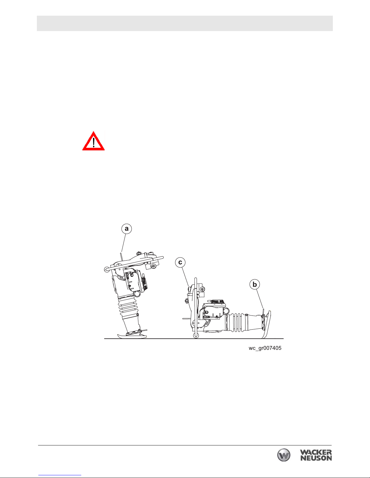
4.1 Lifting and Transporting
See Graphic: wc_gr007405
4.1.1 Always shut off the engine and close the fuel valve when transporting
the machine.
4.1.2 Make sure the lifting device has enough capacity to hold the machine
(see identification plate on the machine for weight).
4.1.3 Use the central lifting point (a) when lifting the machine.
Always inspect the lifting cable (a) for wear, damage, or abuse. Protect
the cable from any sharp edges. Do not use the cable if there are any
WARNING
4.1.4 Tie down the machine on the vehicle to prevent it from tipping, falling,
signs of cut wires, excessive wear, or other defects. Replace the
damaged cable immediately to avoid injury or death.
or rolling. Lay the machine down flat and tie it to the vehicle at points
(a) and (b).
NOTICE: Drain the fuel tank as required to prevent fuel leaking from
cap (c).
wc_tx001532gb.fm 25
Page 26

Operation BS 60-2i, BS 70-2i
5 Operation
5.1 Preparing the Machine for First Use
Preparing for first use
To prepare your machine for first use:
5.1.1 Make sure all loose p ackaging materials have been removed from the
machine.
5.1.2 Check the machine and its components for damage. If there is visible
damage, do not operate the machine! Contact your Wacker Neuson
dealer immediately for assistance.
5.1.3 Take inventory of all items included with the machine and verify that
all loose components and fasteners are accounted for.
5.1.4 Attach component parts not already attached.
5.1.5 Add fluids as needed and applicable, including fuel, engine oil, and
battery acid.
5.1.6 Move the machine to its operating location.
5.2 Recommended Fuel
The engine requires regular grade unleaded gasoline and Wacker
Neuson two-cycle oil or equivalent. Use only fresh, clean gasoline.
Gasoline containing water or dirt will damage fuel system. Refer to the
technical data for further information.
26 wc_tx000919gb.fm
Page 27

BS 60-2i, BS 70-2i Operation
5.3 Position of the Operator
For optimal control, performance, and minimal hand/arm vibration
follow the guidelines below when using the machine.
• Grasp the handle with both hands as shown.
Hand/Arm Vibration (HAV) has been optimized for the hand position shown.
Reported HAV levels are measured at
position
and ISO 5349.
• Run the rammer at full throttle.
• Walk behind the rammer.
A in conformance with EN 1033
• Use the handle to guide the rammer’s direction of travel. Allow
the rammer to pull itself forward. Do not try to overpower the
rammer.
• If you need to lift the rammer while operating, position the throttle
in the SLOW position. Position the rammer as needed then,
continue operation with the throttle in the FAST position.
For best compaction and shoe wear , the shoe must hit the ground flat
(b), not on its toe or heel.
If the rammer should tip on its side during operation, place the
rammer in the position shown (c) and shut off the engine.
wc_tx000919gb.fm 27
Page 28

Operation BS 60-2i, BS 70-2i
5.4 Before Starting
5.4.1 Read safety instructions at the beginning of this manual.
5.4.2 Make sure that the gas tank is full, and that the oil tank is at least ¼ full.
5.4.3 Place rammer on loose soil or gravel. DO NOT start rammer on hard
surfaces such as asphalt or concrete.
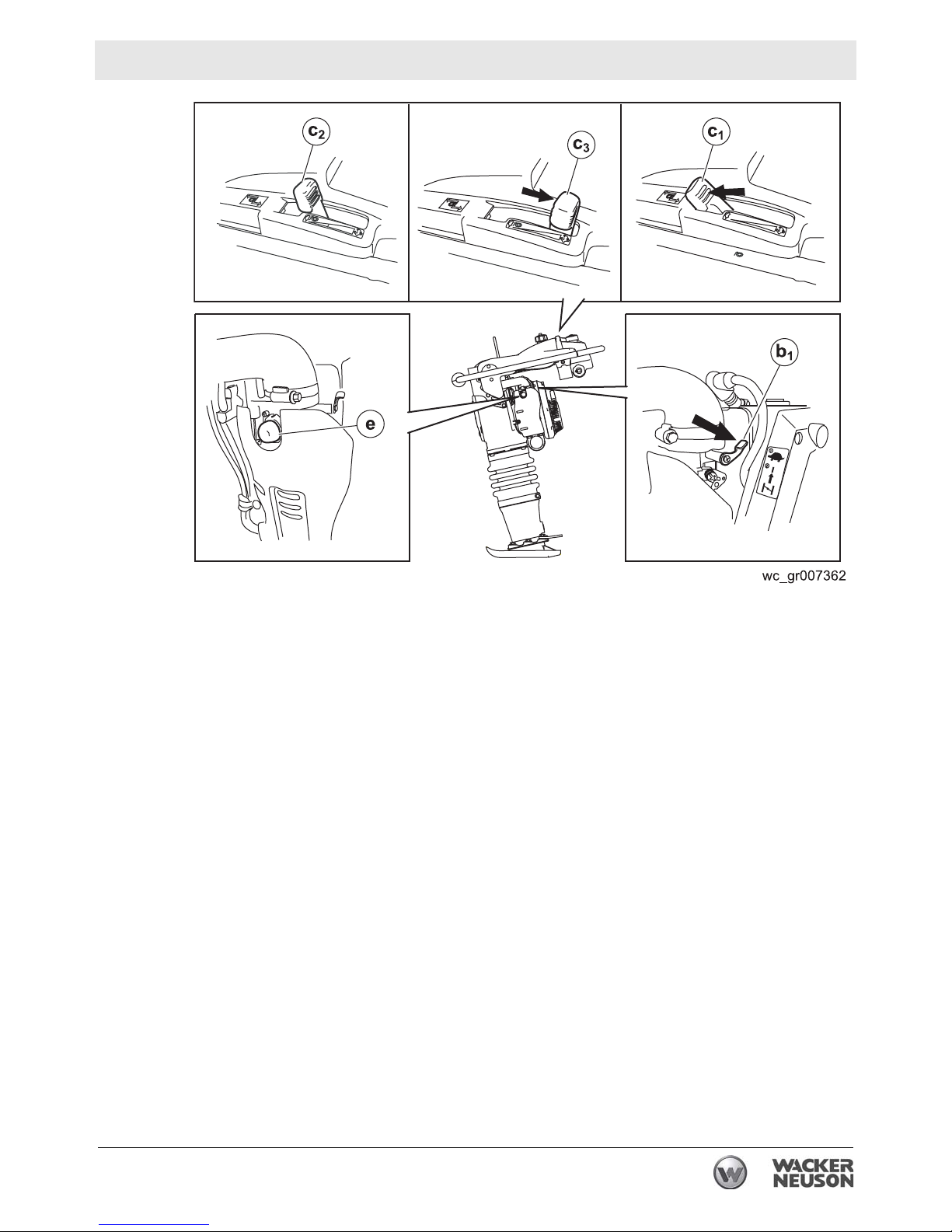
5.5 Starting
See Graphic: wc_gr007362
5.5.1 Set the throttle to the idle position (c2). This will automatically turn on
the flow of fuel.
5.5.2 Close the choke (b1).
5.5.3
5.5.4 Pull starter rope. Repeat until engine starts.
5.5.5 Open the throttle to the full position (c3). The choke will open
Pump the purge bulb
Note: The engine will not become flooded by pumping the purge bulb
more than 10 times. Pumping the purge bulb removes air from the fuel
system. It does not pump fuel into the carburetor.
Multiple pulls (typically less than 5 pulls) may be required to start an
engine:
• that has not been run before.
• that has not been run for a long period of time (a week or more.)
• that has been run completely out of fuel.
• in cold weather conditions.
automatically.
Note: The engine is equipped with a low oil level shutoff switch. If the
engine stops running after 15-30 seconds, check the oil level in the oil
tank and add Wacker Neuson two-cycle oil or equivalent as necessary.
(e)
6 to 10 times or until you see fuel in the bulb.
28 wc_tx000919gb.fm
Page 29
BS 60-2i, BS 70-2i Operation
5.6 Stopping
See Graphic: wc_gr007362
5.6.1 Place throttle in the idle position (c2).
5.6.2 Shut off the engine by moving the throttle through the detent to the off
position (c1). The engine will stop and the fuel valve will close.
5.7 Emergency Shutdown Procedure
Procedure
If a breakdown or accident occurs while the machine is operating,
follow the procedure below:
5.7.1 Reduce engine speed to idle.
5.7.2 Stop the engine.
5.7.3 Close the fuel valve.
5.7.4 Contact the rental yard or machine owner for further instructions.
wc_tx000919gb.fm 29
Page 30

Maintenance BS 60-2i, BS 70-2i
6 Maintenance
6.1 Periodic Maintenance Schedule
The table below lists basic machine maintenance. Tasks designated
with check marks may be performed by the operator. Tasks
designated with square bullet points require special training and
equipment.
Check fuel level.
Check engine oil level.
Check air filter indicator. Replace as
needed.
Check ramming system oil level in
sightglass.
Check fuel line and fittings for cracks or
leaks. Replace as needed.
Tighten ramming shoe hardware.
Check engine cylinder screws.
Check external hardware.
Clean engine cooling fins.
Daily
before
starting
3
3
3
3
After
first
5
hours
33
Every
week
or 25
hours
3
Every
month
or 100
hours
Every
3 months
or 300
hours
Every
Year
Clean and check spark plug gap.
Replace spark plug.
Clean recoil starter.
Change ramming system oil.*
Clean engine muffler and exhaust port.
Inspect lifting cable for wear, damage,
or abuse.
Inspect fuel filter.
* Change ramming system oil after first 50 hours of operation.
Note: If engine performance is poor, check, clean, and replace air filter elements as needed.
3
3
30 wc_tx000924gb.fm
Page 31
BS 60-2i, BS 70-2i Maintenance
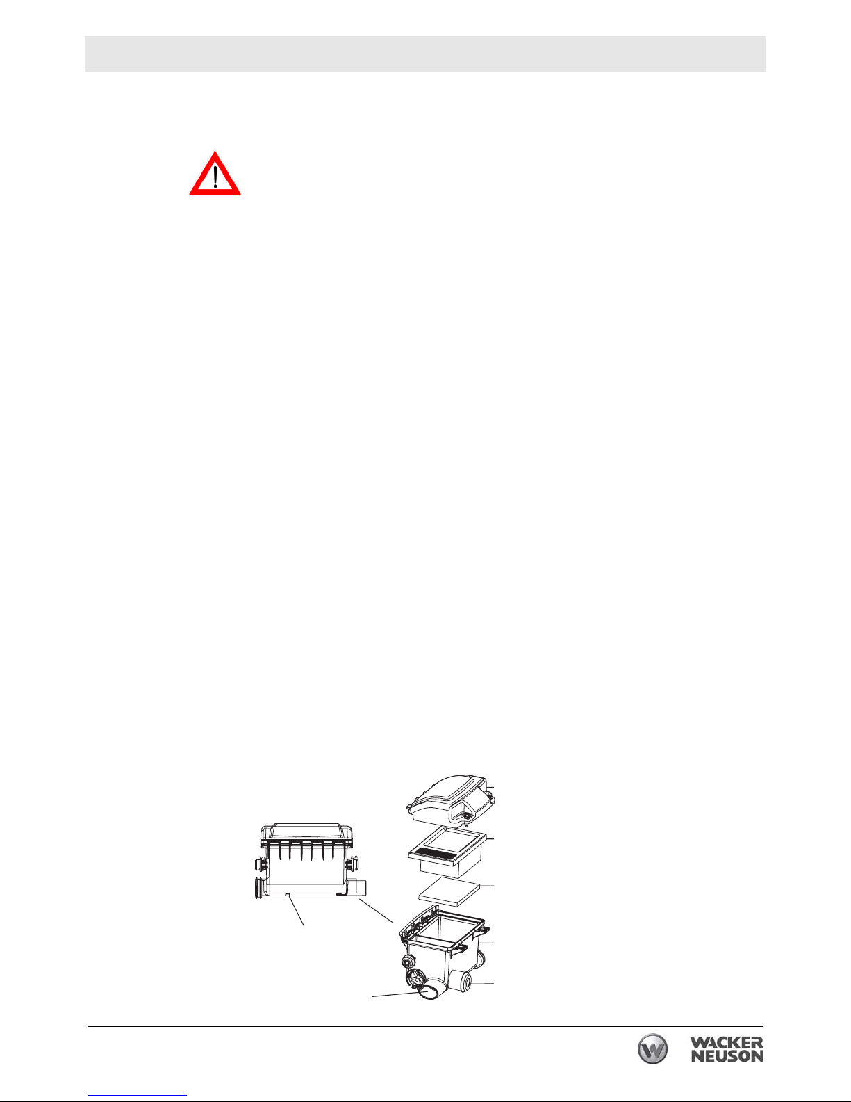
6.2 Servicing the Air Cleaner
See Graphic: wc_gr001168
NEVER use gasoline or other types of low flash point solvents for
cleaning the air filter. A fire or explosion could result.
WARNING
NOTICE: NEVER run engine without main paper filter element (b).
Severe engine damage will occur.
Filter Indicator
The air intake system is equipped with a filter indicator (h), which
indicates when a filter change is required. Replace the main paper filter
element (b) when the yellow plunger of the indicator appears in or near
the red line. Push and hold in the yellow plunger on top of the indicator
to reset it after replacing the main paper filter element.
Clean elements using the following procedure:
6.2.1 Remove the air cleaner cover (a). Remove the main paper filter
element (b) and the secondary prefilter (c) and inspect them for holes
or tears. Replace the elements if they are damaged.
6.2.2 Main paper filter element (b): Replace the main paper filter element if
it appears heavily soiled and/or when the yellow plunger of indicator
appears in or near the red line.
6.2.3 Prefilter (c): Clean it with low-pressure compressed air. When the
prefilter is very soiled, wash it in a solution of mild detergent and warm
water. Rinse it thoroughly in clean water. Allow the prefilter to dry
thoroughly before reinstalling it.
Note: Do not oil the prefilter.
6.2.4 Wipe out the filter housing (d) with a clean cloth. Do not use
compressed air.
NOTICE: Do not allow dirt to get into the engine intake port (k) while
cleaning. Damage to engine will result.
6.2.5 Check that the precleaner debris ejector slot (i) is clear.
a
b
c
wc_tx000924gb.fm 31
i
k
wc_gr001168
d
h
Page 32

Maintenance BS 60-2i, BS 70-2i
6.3 Checking and Changing the Ramming System Oil
Background
Lubricating oil is distributed throughout the ramming system by the
action of the rammer. Holes drilled in the piston carry oil from the
bottom of the rammer to the crankcase as the rammer operates. Oil in
the ramming system must be maintained at the correct level to ensure
the ramming system operates efficiently.
Checking the oil level
Perform the following procedure to check the ramming system oil
level.
Note: If the Rammer has been transported in the horizontal position or has
recently been used, upright it and allow it to stand in the upright position for
15 minutes before checking the oil level. This will allow the oil to settle and
provide a more accurate reading.
6.3.1 Tip the rammer so that it is perpendicular with the ground.
6.3.2 Check the oil through the sightglass (a).
The correct oil level will fill 1/2 to 3/4 of the sightglass. Add more oil if
necessary.
Adding oil
Perform the following procedure to add oil to the ramming system.
NOTICE: Do not overfill the ramming system with oil. Excessively high
levels of oil can create a hydraulic lock in the ramming system. This
can result in erratic operation and cause damage to the engine clutch,
the ramming system, and the shoe.
6.3.3 Tip the Rammer forward to allow access to the sightglass. Secure the
Rammer in this position.
32 wc_tx000924gb.fm
Page 33

BS 60-2i, BS 70-2i Maintenance
6.3.4 Remove the sightglass. Clean the threads of the sightglass, then
wrap the threads with Teflon tape.
6.3.5 Add oil to the machine through the sightglass opening in the housing.
6.3.6 Stand the machine upright to check the oil level. Add enough oil so
that when the machine is upright, oil will fill 1/2 to 3/4 of the sightglass.
At that point, install the sightglass. Torque the sightglass to 9 Nm (6
ft.lbs.).
Changing oil
Perform the following procedure to change the ramming system oil.
Note: Dispose of used oil in accordance with local environmental regulations.
6.3.7 Remove the drain plug (b). (On BS 50 machines, remove the
sightglass (a).)
6.3.8 Tilt the rammer backward until it is resting on the handle and drain the
oil into a suitable container.
Note: It may take up to 10 minutes for the oil to drain.
6.3.9 Reinstall the drain plug. Torque it to 54 Nm (40 ft.lbs.).
6.3.10 Add oil as stated above.
wc_tx000924gb.fm 33
Page 34

Maintenance BS 60-2i, BS 70-2i
6.4 Shoe Hardware
See Graphic: wc_gr005385
On new machines, or after replacing shoe, check and tighten shoe
hardware after the first 5 hours of operation. Inspect hardware every
week thereafter.
Torque hardware as specified.
Cast Iron Shoe Plastic Shoe
T5
T3
wc_gr005385
T1
T1
T5
T3
Torque Nm Ft.lbs.
T1 86 63
T3 19 14
T5 78.7 58
34 wc_tx000924gb.fm
Page 35

BS 60-2i, BS 70-2i Maintenance
6.5 Adjusting the idle speed
See Graphic: wc_gr007402
Refer to Technical Data for correct idle and operating rpm. For best
accuracy, use a tachometer when making idle speed adjustments.
6.5.1 Remove the guard (c).
6.5.1 Start the engine and allow it to warm up to operating temperature.
6.5.2 Set the engine idle speed with engine running at idle and choke (a) fully
open. Adjust idle speed screw (b), in or out, to obtain correct idle
speed.
NOTICE: DO NOT turn the adjusting screw in too tight or you may
damage the carburetor.
6.5.3 Reinstall the guard.
wc_tx000924gb.fm 35
Page 36

Maintenance BS 60-2i, BS 70-2i
6.6 Long-Term Storage
Introduction
Extended storage of equipment requires preventative maintenance.
Performing these steps helps to preserve machine components and
ensures the machine will be ready for future use. While not all of
these steps necessarily apply to this machine, the basic procedures
remain the same.
When
Prepare your machine for extended storage if it will not be operated
for 30 days or more.
Preparing for storage
Follow the procedures below to prepare your machine for storage.
• Complete any needed repairs.
• Replenish or change oils (engine, exciter , hydraulic & gear-case)
per the intervals specified in the Scheduled Maintenance table.
• Grease all fittings and, if applicable, repack bearings.
• Inspect engine coolant. Replace coolant if it appears cloudy, is
more than two seasons old, or does not meet the average lowest
temperature for your area.
• If your machine has an engine equipped with a fuel valve, start
the engine, close the fuel valve, and run the engine until it stops.
• Consult the engine owner’s manual for instructions on preparing
the engine for storage.
Stabilizing the fuel
After completing the procedures listed above, fill the fuel tank
completely and add a high-quality stabilizer to the fuel.
• Choose a stabilizer that includes cleaning agents and additives
designed to coat/protect the cylinder walls.
• Make sure the stabilizer you use is compatible with the fuel in
your area, fuel type, grade and temperature range. Do not add
extra alcohol to fuels which already contain it (for example, E10).
• For engines with diesel fuel, use a stabilizer with a biocide to
restrict or prevent bacteria and fungus growth.
• Add the correct amount of stabilizer per the manufacturer’s
recommendations.
36 wc_tx000924gb.fm
Page 37

BS 60-2i, BS 70-2i Maintenance
Storing the machine
Perform these remaining steps to store your machine.
• Wash the machine and allow it to dry.
• Move the machine to a clean, dry, secure storage location. Block
or chock wheels to prevent machine movement.
• Use touch-up paint as needed to protect exposed metal against
rust.
• If the machine has a battery, either remove or disconnect it.
NOTICE: Allowing the battery to freeze or completely discharge is
likely to cause permanent damage. Periodically charge the battery
while the machine is not in use. In cold climates, store and charge the
battery indoors or in a warm location.
• Cover the machine. Tires and other exposed rubber items should
be protected from the weather. Either cover them or use a readily
available protectant.
wc_tx000924gb.fm 37
Page 38

Basic Troubleshooting BS 60-2i, BS 70-2i
7 Basic Troubleshooting
Problem / Symptom Reason / Remedy
Engine does not start, or
stalls.
Engine does not accelerate, is
hard to start, or runs erratically.
Engine overheats. • Clean cooling fins and fan blades.
Engine runs, rammer does not
tamp.
• No fuel in tank.
• Low oil level in tank.
• Spark plug fouled.
• Fuel valve closed.
• Low oil level in tank.
• Spark plug fouled.
• Clean muffler and exhaust port.
• Crankshaft seals are leaking.
• Check air cleaner.
• Inspect clutch for damage. Replace if necessary.
• Broken connecting rod or crankgear.
Engine runs, rammer opera-
tion is erratic.
Engine shuts off after idling for
an extended period.
• Low engine performance. Compression loss.
Plugged exhaust port.
• Oil/grease on clutch.
• Broken/worn springs.
• Soil buildup on ramming shoe.
• Broken parts in ramming system or crankcase.
• Engine operating speed is too high.
• The engine has a feature that automatically
shuts itself off after running at idle speeds for
approximately 17 ½ minutes.
38 wc_tx001533gb.fm
Page 39

BS 60-2i, BS 70-2i Technical Data
8 Technical Data
8.1 Rammer
Engine Power Rating
Net power rating per 80/1269/EEC and ISO 3046-1. Actual power
output may vary due to conditions of specific use.
Item Number:
Engine model
Engine speed - operating
Engine speed - idle
Max. rated power @ rated speed
Clutch engagement
Spark plug
Electrode gap
Cylinder head
compression (cold)
Air cleaner
BS 60-2i
0009339
0009419
0620613
Rammer
type
rpm
rpm
kW(Hp)
rpm
type
mm (in)
bar/cm
(psi)
type
3
1.8 (2.4) @ 4400 rpm
Three stage with cyclonic precleaner
BS 60-2i
0009393
0009420
0620614
WM80
4400 ± 100
2000 ± 100
2500 ± 100
Champion RL95YC
0.5 (0.020)
8.0–9.7 (120–140)
BS 70-2i
0009341
0009401
0009426
0009428
2.0 (2.7) @
4400 rpm
Engine lubrication
Fuel tank capacity
Fuel
Fuel consumption
Running time
Oil tank capacity
Ramming system lubrication
Ramming system capacity
wc_td000284gb.fm 39
oil grade
l (qts.)
type
l(qt.)/hr
hour
l (qts.)
oil grade
ml (oz.)
Wacker Neuson two-cycle or other oil meet-
ing the NMMA TC-W3 specification
3.0 (3.2)
Regular unleaded gasoline
1.2 (1.3) 1.4 (1.3)
2.5 2.3
0.70 (0.75)
SAE 10W30
890 (30)
Page 40

Technical Data BS 60-2i, BS 70-2i
8.2 Sound Measurements
Products are tested for sound pressure level in accordance with EN
ISO 11204. Sound power level is tested in accordance with European
Directive 2000/14/EC - Noise Emission in the Environment by
Equipment for use outdoors.
• the sound pressure level at operator's location (LpA):
BS 60-2 = 98 dB(A)
BS 70-2 = 92 dB(A).
• the guaranteed sound power level (LWA) = 108 dB(A).
8.3 Vibration Measurements
Products are tested for hand/arm vibration (HAV) level in accordance
with ISO 5349, EN1033, and EN500-4 where applicable.
• HAV BS 60-2i = 7.6 m/s
• HAV BS 70-2i = 6.8 m/s
2
2
Refer to Section Proper Operation for further details.
40 wc_td000284gb.fm
Page 41

BS 60-2i, BS 70-2i Technical Data
8.4 Dimensions
Machine Item Number
BS 60-2i
0009339
0009393
0009419
0009420
0620613
0620614
BS 70-2i
0009341
0009401
0009426
0009428
A
mm (in.)
280 (11.02)
280 (11.02)
280 (11.02)
280 (11.02)
280 (11.02)
280 (11.02)
330 (12.99)
280 (11.02)
330 (12.99)
280 (11.02)
B
mm (in.)
336 (13.25)
342 (13.45)
336 (13.25)
342 (13.45)
336 (13.25)
342 (13.45)
342 (13.45)
336 (13.25)
342 (13.45)
336 (13.25)
wc_td000284gb.fm 41
Page 42

Page 43

EC DECLARATION OF CONFORMITY
WACKER NEUSON CORPORATION, N92W15000 ANTHONY AVENUE, MENOMONEE FALLS, WISCONSIN USA
AUTHORIZED REPRESENTATIVE IN THE EUROPEAN UNION Axel Häret
WACKER NEUSON SE
Preußenstraße 41
80809 München
hereby certifies that the construction equipment specified hereunder:
1. Category:
Vibratory Rammer
2. Machine function:
This machine is intended to be used for compacting cohesive, mixed, and granular soils in confined areas.
3. Type / Model
Rammer BS 60-2, BS 60-2i, BS 70-2, BS 70-2i
4. Item number of equipment:
0009417, 0009421, 0009419, 0009420, 0009424, 0009425, 0009427, 0009426, 0009428
5. Net installed power:
BS 60-2, BS 60-2i 1,8 kW
BS 70-2, BS 70-2i 2,0 kW
Has been sound tested per Directive 2000/14/EC:
Conformity Assessment
Procedure
ANNEX VIII Lloyds Register Quality
Name and address of notified body Measured sound power level Guaranteed sound power level
106 dB(A) 108dB(A)
Assurance Limited (Notified
Body No 0088)
71 Fenchurch Street
London EC3M 4BS
United Kingdom
6. This machinery fulfills the relevant provisions of Machinery Directive 2006/42/EC and is also produce d in accordan ce with
these standards:
2000/14/EC
2004/26/EC
2004/108/EC
EN 500-1
EN 500-4
12-18-09
Date
William Lahner Paul Sina
Vice President of Engineering Manager, Product Engineering
The original language of this EC Declaration of Conformity is American English.
2010-CE-BS60-2--BS70-2_en.fm
WACKER NEUSON CORPORATION
Page 44

Wacker Neuson SE · Preußenstraße 41 · D-80809 München · Tel.: +49-(0)89-3 54 02-0 · Fax: +49 - (0)89-3 54 02-390
Wacker Neuson Corporation · N92W15000 Anthony Ave. · Menomonee Falls, WI 53051 · Tel. : (262) 255-0500 · Fax: (262) 255-0550 ·Tel. : (800) 770-0957
Wacker Neuson Limited - Room 1701–03 & 1717–20, 17/F. Tower 1, Grand Century Place, 193 Prince Edward Road West, Mongkok, Kowloon, Hongkong.
Tel: (852) 3605 5360, Fax: (852) 2758 0032
 Loading...