

Page 1

Item Number / Artikel-Nummer / Número de referencia / Numéro de référence :
0007567, 0007566
This manual is divided into the sections listed below:
Diese Betriebsanleitung ist in folgende Kapitel eingeteilt:
Este manual está compuesto por las siguientes secciones:
Ce manuel contient les sections suivantes:
BS65Y
Operation
1A
Betrieb
1B
Operación
1C
Opération
1D
Machine Parts / Maschinenteile / Repuestos de la máquina / Pièces de la machine
2
This manual provides information and procedures to safely operate and maintain this WACKER model. For your
own safety and protection from injury, carefully read, understand and observe the safety instructions described
in this manual. THE INFORMATION CONTAINED IN THIS MANUAL WAS BASED ON MACHINES IN PRODUCTION
AT THE TIME OF PUBLICATION. WACKER CORPORATION RESERVES THE RIGHT TO CHANGE ANY PORTION
OF THIS INFORMATION WITHOUT NOTICE.
(English)
(Deutsch)
(Español)
(Français)
WARNING
!
Engine exhaust, some of its constituents, and certain vehicle
components contain or emit chemicals known to the State of
California to cause cancer and birth defects or other
reproductive harm.
1040SD71
Diese Betriebsanleitung enthält Informationen und Verfahren, um dieses WACKER Gerät sicher zu bedienen und zu
warten. Für Ihre Sicherheit und zur Verhinderung von Verletzungen, diese Betriebsanleitung bitte genau durchlesen
und die Angaben befolgen. DIE HIERIN ENTHALTENEN INFORMATIONEN SIND AKTUELL ZUM ZEITPUNKT DER
VERÖFFENTLICHUNG. ÄNDERUNGSRECHT VORBEHALTEN.
Este manual contiene información y procedimientos que son necesarios para operar y mantener esta máquina
WACKER. Para su propia seguridad y protección, lea por favor este manual cuidadosamente y observe todas las
instrucciones de seguridad descritas en este manual. TODA LA INFORMACION EN ESTE MANUAL SE BASA EN
MAQUINAS EN PRODUCCION VEGENTE A PARTIR DE LA FECHA DE PUBLICACION. TODOS DERECHOS
RESERVADOS POR WACKER CORPORACION.
Ce manuel fournit des informations et des procédures destinées à utiliser et à entretenir en toute sécurité cette machine
WACKER. Pour votre propre sécurité et afin d’éviter tout accident, lisez, comprenez et respectez soigneusement les
consignes de sécurité décrites dans ce manuel. LES INFORMATIONS CONTENUES DANS CE MANUEL SONT
BASEES SUR LES MACHINES EN COURS DE PRODUCTION AU MOMENT DE LA PUBLICATION. WACKER
CORPORATION SE RESERVE LE DROIT DE MODIFIER TOUTE PARTIE DE CES INFORMATIONS SANS
PREAVIS.
i
Page 2
BS65Y
Rev. Serial Number
MENOMONEE FALLS, WI USA 53051
hpkWlbs
dB(A) Manuf. Yr.
Model
kg
MADE
IN USA
Item Number
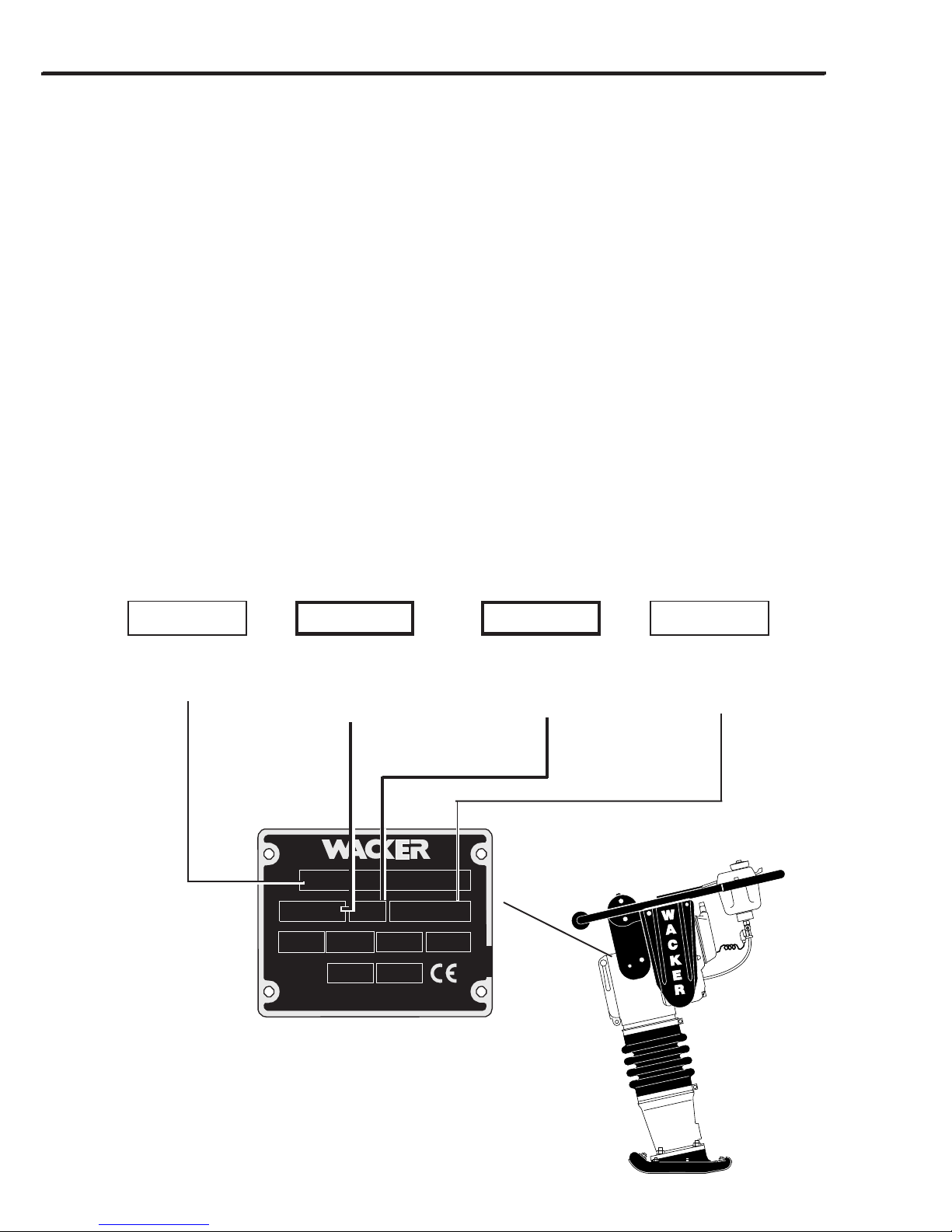
Nameplate / Typenschild / Placa de Identificación / Plaque signalétique
A nameplate listing the Model Number, Item Number, Revision, and Serial Number is attached to each unit. Please
record the information found on this plate so it will be available should the nameplate become lost or damaged. When
ordering parts or requesting service information, you will always be asked to specify the model, item number,
revision number, and serial number of the unit.
Ein Typenschild mit Typ, Artikelnummer, Version und Maschinen-Nummer ist an jedem Gerät angebracht. Die Daten
von diesem Schild bitte notieren, damit sie auch bei Verlust oder Beschädigung des Schildes noch vorhanden sind.
Der Typ, die Artikel-Nummer, die Versions-Nummer und die Maschinen-Nummer sind bei der Ersatzteilbestellung
oder Nachfragen bezüglich Service-Informationen stets erforderlich.
Una placa de identificación con el modelo, número de referencia, nivel de revisión y número de serie ha sido añadida
en cada máquina. Favor de anotar los datos en la placa en caso de que la placa de identificación sea destruida o
perdida. En todos los pedidos para repuestos necesita siempre el modelo, el número de referencia, el nivel de
revisión y el número de serie de la máquina en cuestión.
Une plaque signalétique mentionnant le modèle, le numéro de référence, le niveau de revision et le numéro de série
est fixée sur chaque machine. Veuillez noter les informations relevées sur cette plaque de façon à ce qu’elles soient
toujours disponibles si la plaque signalétique venait à être perdue ou endommagée. Lorsque vous commandez des
pièces détachées ou vous sollicitez des informations auprès-vente, on vous demandera toujours de préciser
le modèle, le numéro de référence, le niveau de revision et le numéro de série de la machine.
My machine’s numbers are / Die Nummern meines Gerätes sind /
Los números de mi máquina son / Les numéros de ma machine sont :
Model number
Typ
Modelo
Modèle
Item Number
Artikel-Nummer
Número de referencia
Numéro de référence
BS65YBS65Y
BS65Y
BS65YBS65Y
0001010100010101
00010101
0001010100010101
101101
00075660007566
0007566
00075660007566
101
101101
Revision
Version
Nivel de revisión
Niveau de revision
88223
Serial Number
Maschinen-Nummer
Número de Serie
Numéro de Série
WACKER
1014SD91
ii
Page 3

This machine may be covered by one or more of the following patents:
111891
OF THESE U.S. PATENTS:
4643611; 4555238; 5564375; 5586630; 4419048
WACKER MACHINES PROTECTED BY ONE OR MORE
Dieses Gerät ist unter einem oder mehreren der folgenden Patente geschützt:
Puede ser que las patentes a continuación sean válidas para esta máquina:
Cette machine peut être protégée sous les brevets d’invention ci-dessous :
BS65Y
PATENT PENDING
111545
Keep this manual or a copy of it with the machine. If you lose this manual or need an
additional copy, please contact WACKER Corporation. This machine is built with user
safety in mind, however, it can present hazards if improperly operated and serviced.
Follow operating instructions carefully! If you have questions about operating or
servicing this equipment, please contact WACKER Corporation.
Diese Betriebsvorschrift oder eine Kopie stets mit der Maschine aufbewahren. Weitere
Kopien sind von WACKER Corporation erhältlich. Diese Maschine ist unter Betracht der
Verbrauchersicherheit entwickelt, kann jedoch bei unfachgemäßem Gebrauch oder Wartung
Gefahren darstellen. Die Vorschriften genauestens befolgen! Sollten Sie Fragen bezüglich
Betrieb oder Service dieser Maschine haben, so steht WACKER Corporation Ihnen gerne zur
Verfügung.
Mantenga este manual o una copia de el con la máquina. Si se pierde o si Ud. desea un
ejemplar adicional, favor comunicarse con WACKER. Esta máquina fue fabricada con la
seguridad del usuario en mente; sin embargo, situaciones peligrosas pueden presentarse
si la máquina es utilizada o mantención es dada inapropiadamente. Siga las instrucciones
de operación cuidadosamente. Si Ud. tiene preguntas acerca de la operación o mantención
de este equipo, favor de comunicarse con WACKER CORPORATION.
Conserver ce manuel ou une copie de celui-ci avec la machine. Si vous perdez ce manuel
ou que vous avez besoin d’un exemplaire supplémentaire, veuillez contacter WACKER
Corporation. Cette machine est construite dans le soucis de la sécurité de l’utilisateur, elle
peut cependant présenter des dangers si elle est utilisée et entretenue de façon incorrecte.
Respectez attentivement les consignes d’utilisation ! Si vous avez des questions concernant
l’utilisation ou l’entretien de cet équipement, veuillez contacter WACKER Corporation.
iii
Page 4

BS65Y
EMISSION CONTROL SYSTEM
INFORMATION
Source of Emissions
The combustion process produces carbon monoxide,
oxides of nitrogen, and hydrocarbons. Control of hydrocarbons and oxides of nitrogen is very important because, under certain conditions, they react to form photochemical smog when subjected to sunlight. Carbon
monoxide does not react in the same way, but it is toxic.
WACKER utilizes lean carburetor settings and other
systems to reduce the emissions of carbon monoxide,
oxides of nitrogen, and hydrocarbons.
The U.S. and California Clean Air Acts
EPA and California regulations require all manufacturers
to furnish written instructions describing the operation
and maintenence of emission control systems.
The following instructions and procedures must be followed in order to keep the emissions from your WACKER
engine within the emissions standards.
Tampering and Altering
Tampering with or altering the emission control system
may increase emissions beyond the legal limit. Among
those acts that constitute tampering are:
• Removal or alteration of any part of the intake, fuel, or
exhaust systems.
• Altering or defeating the speed-adjusting mechanism
to cause the engine to operate outside its design
parameters.
Problems That May Affect Emissions
If you are aware of any of the following symptoms, have
your engine inspected and repaired by your servicing
dealer.
• Hard starting or stalling after starting.
• Rough idle.
• Misfiring or backfiring under load.
• Afterburning (backfiring).
• Black exhaust smoke or high fuel consumption.
Replacement Parts
The emission control systems on your WACKER engine
were designed, built, and certified to conform with EPA
and California emissions regulations. We recommend
the use of genuine WACKER parts whenever you have
maintenence done. These original-design replacement
parts are manufactured to the same standards as the
original parts, so you can be confident of their performance. The use of replacement parts that are not of the
original design and quality may impair the effectiveness
of your emission control system.
A manufacturer of an aftermarket part assumes the
responsibility that the part will not adversely affect emission performance. The manufacturer or rebuilder of the
part must certify that use of the part will not result in a
failure of the engine to comply with emission regulations.
Maintenance
Follow the maintenance schedule. Remember that this
schedule is based on the assumption that your machine
will be used for its designed purpose. Sustained highload or high-temperature operation, or use in unusually
wet or dusty conditions, will require more frequent service.
OXYGENATED FUELS
Some conventional gasolines are being blended with
alcohol or an ether compound. These gasolines are
collectivly referred to as oxygenated fuels. To meet clean
air standards, some areas of the United States and
Canada use oxygenated fuels to help reduce emissions.
If you use an oxygenated fuel, be sure it is unleaded and
meets the minimum octane rating requirement.
Before using an oxygenated fuel, try to confirm the fuel’s
contents. Some states / Provinces require this information to be posted on the pump.
The following are EPA approved percentages of oxygenates:
ETHANOL - (ethyl or grain alcohol) 10% by volume. You
may use gasoline containing up to 10% ethanol by
volume. Gasoline containing ethanol may be marketed
under the name “Gasohol”.
MTBE - (methyl tertiary butyl ether) 15% by volume. You
may use gasoline containing up to 15% MTBE by volume.
METHANOL - (methyl or wood alcohol) 5% by volume.
You may use gasoline containing up to 5% methanol by
volume, as long as it contains cosolvents and corrosion
inhibitors to protect the fuel system. Gasoline containing
more than 5% methanol by volume may cause starting
and/or performance problems. It may also damage metal,
rubber, and plastic parts of your fuel system.
If you notice any undesirable operating symptoms, try
another service station, or switch to another brand of
gasoline.
Fuel system damage or performance problems resulting from the use of an oxygenated fuel containing more than the percentages of oxygenates mentioned above are not covered under warranty.
iv
Page 5

BS65Y
Emission Control System Warranty
Your new WACKER engine complies with the U.S. EPA emissions regulations. WACKER provides the same emission
warranty coverage for engines sold in all 50 states.
YOUR WARRANTY RIGHTS AND OBLIGATIONS
All States
WACKER must warrant the emission control system on your engine for the period of time listed below provided there
has been no abuse, neglect or improper maintenance of your engine. Where a warrantable condition exists, WACKER
will repair your engine at no cost to you including diagnosis, parts and labor.
Your emission control system may include such parts as the carburetor, the ignition system and the catalytic converter.
Also included may be hoses, connectors and other emission-related assemblies.
MANUFACTURER’S WARRANTY COVERAGE:
The 1998 and later engines are warranted for two years. If any emission-related part on your engine is defective, the
part will be repaired or replaced by WACKER.
OWNER’S WARRANTY RESPONSIBILITY:
As the engine owner, you are responsible for the performance of the required maintenance listed in your owner’s
manual. WACKER recommends that you retain all receipts covering maintenance on your engine, but WACKER
cannot deny warranty coverage solely for the lack of receipts or for your failure to ensure the performance of all
scheduled maintenance.
As the engine owner, you should be aware that WACKER may deny you warranty coverage if your engine or a part
has failed due to abuse, neglect, improper maintenance or unapproved modifications.
You are responsible for presenting your engine to a WACKER dealer as soon as a problem exists. The warranty repairs
should be completed in a reasonable amount of time, not to exceed 30 days.
If you have any questions regarding your warranty rights and responsibilities, you should contact your local WACKER
dealer.
WARRANTY COVERAGE:
WACKER engines sold after January 1, 1998, are covered by this Emission Control System Warranty for a period of
two years from the date of delivery to the original retail purchaser. This warranty is transferable to each subsequent
purchaser for the duration of the warranty period.
Warranty repairs will be made without charge for diagnosis, parts or labor. All defective parts replaced under this
warranty become property of WACKER. A list of warranted parts is located on the next page. Normal maintenance
items, such as spark plugs and filters, that are on the warranted parts list are warranted up to the required replacement
interval only.
WACKER is also liable for damages to other engine components caused by a failure of any warranted parts during
the warranty period.
Only WACKER approved replacement parts may be used in the performance of any warranty repairs and must be
provided without charge to the owner. The use of replacement parts not equivalent to the original parts may impair the
effectiveness of your engine emission control system. If such a replacement part is used in the repair or maintenance
of your engine, and an authorized WACKER dealer determines it is defective or causes a failure of a warranted part,
your claim for repair of your engine may be denied. If the part in question is not related to the reason your engine requires
repair, your claim will not be denied.
v
Page 6

BS65Y
TO OBTAIN WARRANTY SERVICE:
You must take your WACKER product along with proof of original purchase date, at your expense, to any WACKER
authorized dealer during their normal business hours. Claims for repair or adjustment found to be caused solely by
defects in material or workmanship will not be denied because the engine was not properly maintained and used.
EXCLUSIONS:
FAILURES OTHER THAN THOSE RESULTING FROM DEFECTS IN MATERIAL OR WORKMANSHIP ARE NOT
COVERED BY THIS WARRANTY. THIS WARRANTY DOES NOT EXTEND TO EMISSION CONTROL SYSTEMS
OR PARTS WHICH ARE AFFECTED OR DAMAGED BY OWNER ABUSE, NEGLECT, IMPROPER MAINTENANCE,
MISUSE, MISFUELING, IMPROPER STORAGE, ACCIDENT AND/OR COLLISION, THE INCORPORATION OF, OR
ANY USE OF, ANY ADD-ON OR MODIFIED PARTS, UNSUITABLE ATTACHMENTS, OR THE UNAUTHORIZED
ALTERATION OF ANY PART.
THIS WARRANTY DOES NOT COVER REPLACEMENT OF EXPENDABLE MAINTENANCE ITEMS MADE IN
CONNECTION WITH REQUIRED MAINTENANCE SERVICES AFTER THE ITEM’S FIRST SCHEDULED REPLACEMENT AS LISTED IN THE MAINTENANCE SECTION OF THE PRODUCT OWNER’S MANUAL, SUCH AS
SPARK PLUGS AND FILTERS.
DISCLAIMER OF CONSEQUENTIAL DAMAGE AND LIMITATIONS OF IMPLIED WARRANTIES:
WACKER DISCLAIMS ANY RESPONSIBILITY FOR INCIDENTAL OR CONSEQUENTIAL DAMAGES SUCH AS
LOSS OF TIME OR THE USE OF THE POWER EQUIPMENT, OR ANY COMMERCIAL LOSS DUE TO THE FAILURE
OF THE EQUIPMENT; AND ANY IMPLIED WARRANTIES ARE LIMITED TO THE DURATION OF THIS WRITTEN
WARRANTY. THIS WARRANTY IS APPLICABLE ONLY WHERE THE U.S. EPA EMISSION CONTROL SYSTEM
WARRANTY REGULATION IS IN EFFECT.
Emission Control System Warranty Parts
SYSTEMS COVERED PARTS
BY THIS WARRANTY DESCRIPTIONS
FUEL METERING CARBURETOR ASSEMBLY
EXHAUST SYSTEM MUFFLER
AIR INDUCTION AIR FILTER HOUSING
AIR FILTER ELEMENT*
IGNITION FLYWHEEL MAGNETO
IGNITION MODULE
SPARK PLUG CAP
SPARK PLUG*
MISCELLANEOUS PARTS TUBING, FITTINGS, SEALS, GASKETS
AND CLAMPS ASSOCIATED
WITH THESE LISTED ITEMS
* Indicates expendable maintenance items.
vi
Page 7

1A OPERATION BS65Y
1.1 Safety Information
This manual contains DANGER, WARNING, CAUTION, and NOTE callouts which must be followed to reduce the
possibility of personal injury, damage to the equipment, or improper service.
This is the safety alert symbol. It is used to alert you to potential
personal injury hazards. Obey all safety messages that follow
!
this symbol to avoid possible injury or death.
!
DANGER
DANGER indicates an imminently hazardous
situation which, if not avoided, will result in
death or serious injury.
!
WARNING
WARNING indicates a potentially hazardous
situation which, if not avoided, could result in
death or serious injury.
!
CAUTION
CAUTION indicates a potentially hazardous
situation which, if not avoided, may result in
minor or moderate injury.
CAUTION: Used without the safety alert symbol,
CAUTION indicates a potentially hazardous situation
which, if not avoided, may result in property damage.
Note:
Contains additional information
important to a procedure.
Laws Pertaining to Spark Arresters
Notice: State Health Safety Codes and Public Resources Codes dictate when an engine
must use a spark arrester. State codes will also specify that a spark arrester be rated by
the United States Forest Service.
The correct spark arresting muffler for use on this machine is WACKER P/N 58406.
1A-2
Page 8

BS65Y OPERATION 1A
1.2 Operating Safety
Familiarity and proper training are required for the safe operation of equipment! Equipment operated improperly or
by untrained personnel can be dangerous! Read the operating instructions and familiarize yourself with the
location and proper use of all instruments and controls. Inexperienced operators should receive instruction from
someone familiar with the equipment before being allowed to operate the rammer.
!
WARNING
NEVER operate rammer in applications for which it
is not intended.
NEVER allow improperly trained personnel to operate rammer.
NEVER use choke to stop engine.
NEVER touch hot muffler, engine cylinders, or
cooling fins. Burns will result.
NEVER use accessories or attachments which are
not recommended by WACKER for rammer. Damage to rammer and/or injury to user may result.
NEVER leave a running machine unattended.
ALWAYS read, understand, and follow procedures
in Operator’s Manual before attempting to operate
equipment.
ALWAYS be sure operator is familiar with proper
safety precautions and operation techniques before using rammer.
ALWAYS wear protective clothing when operating
rammer. For instance, goggles or safety glasses will
protect against eye damage caused by flying debris,
and wearing safety shoes will reduce the chance of
foot injuries.
ALWAYS keep hands, feet, and loose clothing away
from moving parts of rammer.
ALWAYS use common sense and caution when
operating rammer.
ALWAYS be sure rammer will not tip over, roll, slide,
or fall when not being operated.
ALWAYS turn engine OFF when rammer is not being
operated.
ALWAYS close fuel valve when rammer is not being
operated.
ALWAYS remove or disconnect engine spark plug
before servicing rammer, to avoid accidental start-up.
1A-3
Page 9

1A OPERATION BS65Y
1.3 Operator Safety while using Internal Combustion Engines
Internal combustion engines present special hazards during operation and fueling! Failure to follow the safety
guidelines described below could result in severe injury or death.
!
DANGER
NEVER smoke while operating rammer.
NEVER smoke when refueling engine.
NEVER refuel hot or running engine.
NEVER refuel engine near open flame.
NEVER spill fuel when refueling engine.
NEVER operate rammer near open flames.
ALWAYS refill fuel tank in well-ventilated area.
ALWAYS replace fuel tank cap after refueling.
1.4 Service Safety
Poorly maintained equipment can become a safety hazard! In order for the equipment to operate safely and properly
over a long period of time, periodic maintenance and occasional repairs are necessary.
!
WARNING
NEVER attempt to clean or service rammer while it
is running.
ALWAYS replace safety devices and guards after
repairs and maintenance.
NEVER operate equipment with safety devices or
guards removed or not in working order.
NEVER operate equipment without air cleaner.
NEVER remove air cleaner or air cleaner cover while
operating rammer.
NEVER alter engine to run at speeds other than
those specified in Technical Data Section.
1A-4
ALWAYS keep area around muffler free of debris in
order to reduce the chance of an accidental fire.
ALWAYS do Periodic Maintenance as recommended
in Operator’s Manual.
ALWAYS clean debris from engine cooling fins.
ALWAYS replace worn or damaged components
with spare parts designed and recommended by
WACKER for servicing this rammer.
Page 10
BS65Y OPERATION 1A
1.5 Technical Data
Engine speed - full rpm 4500 ± 200
Engine speed - idle rpm 1500 ± 100
Clutch engagement rpm 2800 ± 100
Cylinder head compression-cold
psi (kg/cm2) 120–140 (8.0–9.7)
Spark plug - Gap in. (mm) Champion RL86C: 0.035 (0.8–0.9)
Bosch WR 8 AC: 0.02 (0.5)
P/N 48333
Engine Lubrication oil grade Two-cycle or outboard motor oil conforming to BIA-TC-W
specifications - ratio 50:1
Note: Use 25:1 for first tank of fuel.
Ramming System Lubrication
oil grade SAE 30
oz. (ml) 25 (750)
Sound and Vibration Measurements
The required sound specifications, per Appendix 1, Paragraph 1.7.4.f of the EC-Machine Regulations, are:
- the sound pressure level at operator’s location (LpA) = 93 dB(A)
-
the sound power level (LWA) = 104 dB(A)
These sound values were determined according to ISO 3744 for the sound power level (LWA) and ISO 6081 for the sound
pressure level (LpA) at the operator’s location.
The weighted effective acceleration value, determined according to ISO 8662 Part 1, is 10 m/s2.
The sound and vibration measurements were obtained with the machine operating on crushed gravel at nominal engine
speed.
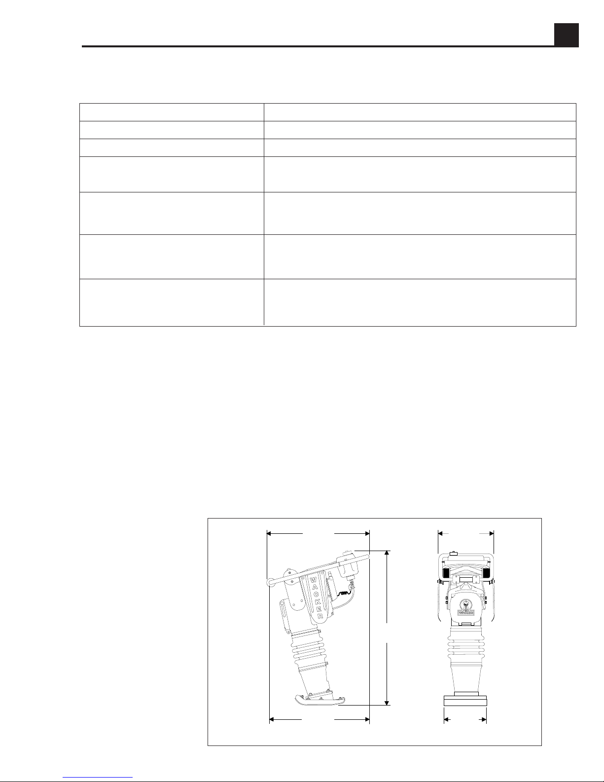
1.6 Dimensions
in. (mm)
WACKER
28 (710)
37
(940)
14 (360)
1014SD89
27 (685)
11 (280)
13 (330)
1A-5
Page 11

1A OPERATION BS65Y
c
c
1
2
c
3
b
1
b
2
f
1002SD08
1.7 Recommended Fuel
This rammer engine requires a two-cycle gasoline/oil
mixture.
Note:
Mix regular unleaded gasoline and two-cycle / outboard
motor oil in separate container before filling tank.
Use 25:1 mixture for first tank of fuel only. Use
50:1 mixture thereafter.
WACKER
d
1002SD27
a
2
1014SD91
1.9 Before Starting
1. Read safety instructions at the beginning of this
manual.
2. Fill tank with proper fuel mixture.
3. Set ramming stroke. Read Sections 1.13 and 1.14.
4. Place rammer on loose soil or gravel. DO NOT start
rammer on hard surfaces such as asphalt or concrete.
a
1
1005SD68
Fuel Ratio 50:1
Gasoline Oil Gasoline Oil
1 gallon 2.5 ounces 5 liters 100 ml
3 gallons 8.0 ounces 10 liters 200 ml
5 gallons 13.0 ounces 15 liters 300 ml
1.8 Application
Rammers are designed to compact loose soils and
gravel to prevent settling and to provide a firm, solid base
for the placement of footings, concrete slabs, foundations, and other structures.
1A-6
1.10 To Start
1. Open fuel valve (a
2. If engine is cold, close choke (b
3. Open throttle no more than 1/4 (c
4. Press button (f) on carburetor twice.
5. Pull starter rope (d) until engine starts.
6. Open choke (b
Note:
Cold engine should run approximately one
(1) minute at idle
).
1
) on carburetor as engine warms up.
2
(c
) on carburetor.
1
).
2
)
to warm up.
1
Page 12
BS65Y OPERATION 1A
1.11 To Stop
1. Place throttle in “IDLE” (c
2. Shut off engine by closing fuel valve
).
1
(a2) on tank.
1.12 Proper Operation
1. Open throttle completely (c
smoothest operation. Do not overthrottle. Best compaction is achieved when rammer is running smoothly.
Normally, a low stroke setting requires a lower engine
speed.
CAUTION: Running the engine too fast will result in
poor operation and unnecessary wear to components.
2. Guide rammer with handle. Allow machine to pull
itself forward. DO NOT try to overpower the machine.
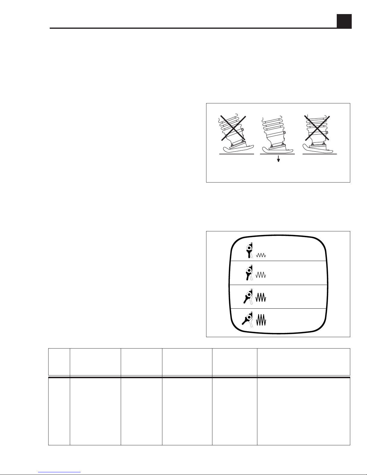
3. For best compaction, shoe must hit the ground flat
(g), not on its toe or heel. This will save on excessive
shoe wear.
), then adjust for the
3
g
1002SD24
1.13 Selecting Ramming Stroke
GLÄTTUNGSARBEIT
The length of the ramming stroke directly affects the
impact force delivered by the rammer. Selecting the best
1
level depends on job requirements and soil conditions.
The label located inside the front cover indicates the
2
general compaction application, together with approximate throttle settings and impact levels for each stroke
level. It should be used as a general guide when
3
selecting ramming stroke.
4
Summary of Stroke and Throttle Settings
Stroke Throttle Percussion Stroke at Single-Stroke Applications
Setting Position Blows/Min. Ramming Shoe Impact in
in. (mm) lbs. (kN)
1 1/4–1/2 750 up to 1 (25) 2040 (9.2) smoothing
2 1/2–3/4 650 up to 2.6 (65) 2640 (11.7) normal compaction
3 3/4–full load 650 up to 3 (75) 3400 (15.1) heavy compaction
LISSAGE
SMOOTHING
APLANAMIENTO
NORMALE VERDICHTUNGSARBEIT
COMPACTAGE NORMAL
NORMAL COMPACTION WORK
COMPACTACION NORMAL
STARKE VERDICHTUNGSARBEIT
COMPACTAGE FORT
HEAVY COMPACTION WORK
COMPACTACION FUERTE
NASSE UND BINDIGE BÖDEN
SOLS HUMIDES ET COHERENTS
WET AND COHESIVE SOILS
SUELOS COHERENTES
39761
4 full load 600 up to 3.2 (80) 3640 (16.2) wet and cohesive soils;
not for hard soils which
are difficult to compact
1A-7
Page 13
1A OPERATION BS65Y
1.14 Adjusting Ramming Stroke
When adjusting the ramming stroke, observe the following precautions to avoid injury to yourself and others.
!
WARNING
- Adjust stroke with machine standing upright and resting on a firm, level surface. Do not adjust stroke if the
machine is in an unstable position where it can easily tip or slide.
- Always stop engine before adjusting stroke. The clutch could engage, causing rammer to jump unexpectedly.
- Adjustment should be performed by one person and with no one else near the machine. The tool used to make
the adjustment could slip out of your hands and hit someone standing nearby.
b
a
1
2
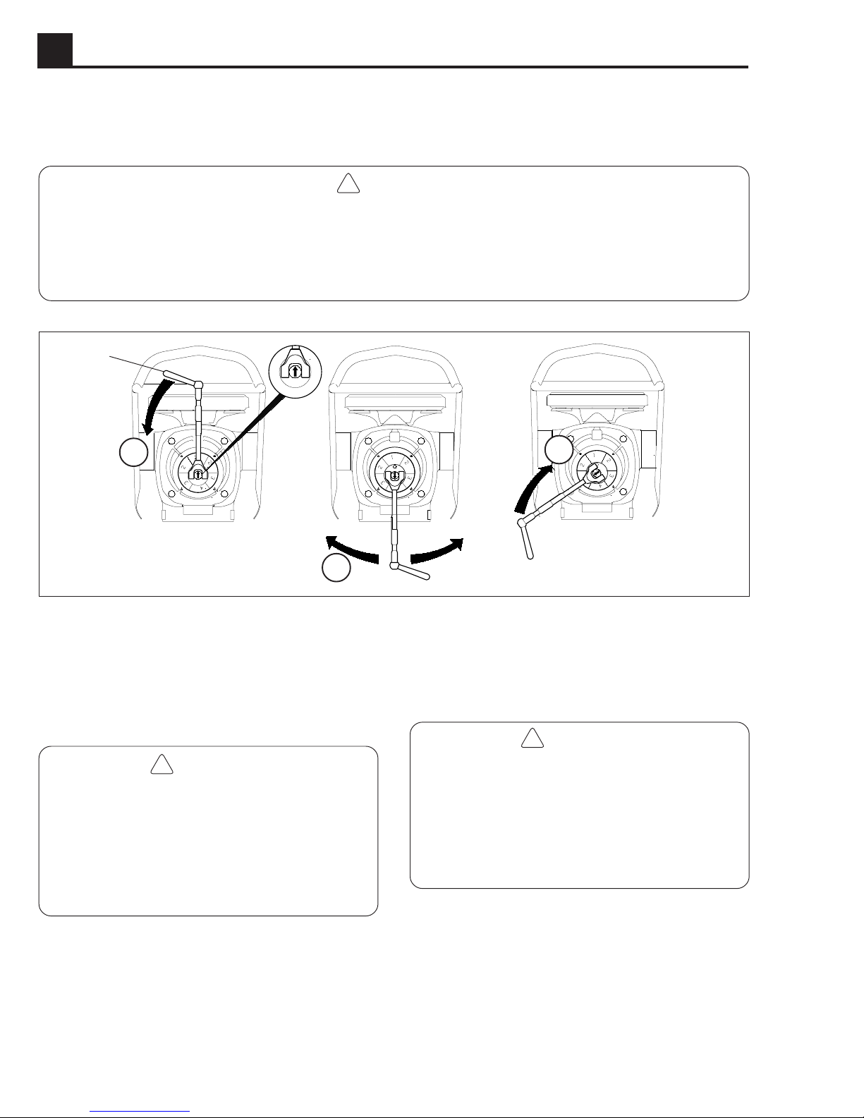
To adjust ramming stroke:
1. Remove adjusting tool from cover. Open cover.
2. Check that arrow (a) on center of locking lever is
pointing up.
!
WARNING
If arrow is pointing down, the spring system is not
balanced and could cause the top half of the rammer
to drop unexpectedly while making the stroke adjustment. To balance spring system, stand behind the
rammer and use guide handle to rock machine back
and forth until you feel the spring system relax. The
arrow should now be facing up.
3. Insert adjusting tool (b) into bore on locking lever.
Make sure it is fully seated so it will not slip out. Steady
rammer by holding guide handle and use adjusting
tool to push locking lever straight down until it is
completely disengaged (refer to Operation 1 in illustration above).
3
1006SD66
4. Using adjusting tool, move locking lever until center
arrow is pointing at the desired stroke setting (Operation 2).
!
WARNING
During this adjustment, tension is applied to the
spring system. This tension will release as the
locking lever is returned back to its locked position.
When this happens, the rammer will settle, causing
the handle and crankcase to drop down. The
movement is slight but happens quickly. Be aware
of this when moving locking lever.
5. Push or pull the adjusting tool to move the locking
lever back to its locked position (Operation 3). When
the locking lever is halfway between the locked and
unlocked position the spring system will settle and
move as described in warning above.
6. Remove adjusting tool. Close cover and lock it in
place with tool.
1A-8
Page 14

BS65Y OPERATION 1A
1.15 Periodic Maintenance Schedule
Daily After Every Every Every
before first week month 3 months
starting 5 or or or
hours 25 hrs. 100 hrs. 300 hrs.
Check fuel level.
Check oil level in sightglass.
Check cannister type air filter.
Replace filter element as required.
Tighten ramming shoe hardware.
Check and tighten engine cylinder screws.
Check and tighten external hardware.
Clean engine cooling fins.
Clean and check spark plug gap.
Replace spark plug.
Clean recoil starter.
Change ramming system oil.*
Clean engine muffler and exhaust port.
* Change ramming system oil after first 50 hours of operation.
1.16 Canister-Type Air Cleaner
1. To remove air cleaner, unsnap spring clips (j), and
remove cover (k) and filter element (l).
2. Gently tap element on flat surface to knock off loose
dirt. Be careful not to damage rubber seals or dent
element. If element is heavily soiled or wet, replace it.
Note:
3. Place element on bracket. Replace cover. By pressing centers of clips in toward cover, the clips will snap
into place. Be sure cover is properly seated and clips
securely in grooves on cover before starting machine.
DO NOT wash or use compressed air to clean
filter element.
k
l
j
1002SD06
1A-9
Page 15

1A OPERATION BS65Y
1.17 Low Maintenance Air Cleaner
This air cleaner is self-cleaning and uses the movement of the machine to shake dust and dirt loose from the air cleaner
element while the rammer is operating. Under normal operating conditions this element will not require cleaning and
should not be removed from the machine. If the element does become plugged with dirt, the engine will begin to lose
power. In this case the air cleaner element can be removed and cleaned as described below. Replace element if it
becomes so plugged with dirt it can no longer be cleaned.
1. Remove the two locknuts from the top of the air
cleaner and lift air cleaner off.
2. Use compressed air directed from the inside of the air
cleaner, through the grommet hole (a), to blow dirt
and dust from element.
CAUTION: Air pressure must not exceed 100 psi.
a
3. Run fresh water through grommet hole
runs clear.
(a) until water
CAUTION: DO NOT use solvents, fuel oil, or gasoline
to wash filter.
4. Plug or cover hole in air cleaner (b) using a cork or
tape to prevent dirty water from entering inside of
element. Soak air cleaner (c) in a solution of warm
water and a low suds detergent for at least 15 minutes. Longer periods of time (up to several hours) of
soaking may be required, depending on how dirty the
element is.
5. Remove air cleaner from wash and repeat rinse
described in Step 3. Allow element to air dry in a dustfree area. DO NOT use heat to speed drying.
6. Inspect grommet before assembly and replace it if it
is worn or damaged. Install grommet on element
carefully to avoid cutting it.
7. Install air cleaner on mount and secure it with washers
and locknuts. DO NOT overtighten. Overtightening
can deform washers and indent top of air cleaner.
b
c
1002SD10
1002SD12
Note:
so it slides easily on mount.
Apply grease or liquid soap to inside of grommet
1A-10
Page 16

BS65Y OPERATION 1A
WACKER
1.18 Lubrication
1. Change ramming system oil after first 50 hours of
operation and every 300 hours thereafter. To drain oil,
remove plug
on handle.
(d) and tilt machine back until it is resting
e
2. With rammer on level surface, add oil through plug
Proper ramming system lubrication is indicated when
approximately 1/2–3/4 of the sightglass (f) is full.
(e).
1.19 Shoe Hardware
On new machines, or after replacing shoe, check and
tighten shoe hardware (g, h) after the first 5 hours of
operation. Inspect hardware every week thereafter.
Torque hardware as specified.
58 ft.lbs.
(79 Nm)
g
f
d
1014SD95
18 ft.lbs.
(25 Nm)
h
1.20 Carburetor Adjustments
Bing Carburetor
Idle Speed
Adjust engine idle speed with the throttle closed and the
engine running at idle. Attach tachometer and set idle
speed screw (i) on carburetor to achieve the specified
idle speed. Refer to “Technical Data”.
No other carburetor adjustments are required.
1004SD06
i
1002SD11
1A-11
Page 17

1A OPERATION BS65Y
WACKER
WACKER
1.21 Long-term Storage
1. Drain fuel from tank.
2. Start engine and run until remaining fuel is used.
3. Remove spark plug. Pour approximately 1 oz. (30 ml) of clean SAE 30W engine oil into cylinder through spark plug
opening.
4. Pull starter rope slowly to distribute oil in engine.
5. Re-install spark plug.
1.22 Transportation
1. Always shut off engine and close fuel valve
when transporting machine.
2. Make sure lifting device has enough capacity
to hold machine (see identification plate on
machine for weight).
3. Use central lifting point (a) when lifting machine.
4. Tie down machine on vehicle to prevent it
from tipping, falling, or rolling. Lay machine
down flat and tie to vehicle at points (b) and
a
(c).
CAUTION: Drain fuel tank as required to
prevent fuel leaking from cap (d).
1.23 Troubleshooting
Problem / Symptom Reason / Remedy
Engine does not start, or stalls. 1. No fuel in tank.
2. Spark plug fouled.
3. Fuel valve closed.
b
d
1014SD90
c
Engine does not accelerate, 1. Improper fuel mix. Too much oil.
is hard to start, or runs erratically. 2. Spark plug fouled.
Engine overheats. 1. Improper fuel mix. Not enough oil.
Engine runs; rammer does not tamp. 1. Inspect clutch for damage. Replace if necessary.
Engine runs, rammer operation is erratic. 1. Oil/grease on clutch.
1A-12
3. Clean muffler and exhaust port.
4. Crankshaft seals are leaking.
5. Air cleaner may be clogged.
2. Carburetor set too lean.
3. Clean cooling fins and fan blades.
2. Broken connecting rod or crankgear.
3. Low engine performance. Compression loss.
Plugged exhaust port.
2. Broken/worn springs.
3. Soil buildup on ramming shoe.
4. Broken parts in ramming system or crankcase.
5. Engine operating speed is too high.
 Loading...