

Page 1

0114549en 010 0510
0114549EN
Repair Manual
Rammer
BS 50 / BS 60 / BS 70
BS 500 / BS 600 / BS 700
BS 65 / BS 650
DS 70 / DS 720
Page 2

Copyright
notice
© Copyright 2010 by Wacker Neuson Corporation.
All rights, including copying and distribution rights, are reserved.
This publication may be photocopied by the original purchaser of the machine. Any
other type of reproduction is prohibited without express written permission from
Wacker Neuson Corporation.
Any type of reproduction or distribution not authorized by W acker Neuson Corporatio n
represents an infringement of valid copyrights. Violators will be prosecuted.
Tra d emarks
All trademarks referenced in this manual are the property of their respective owners.
Manufacturer
Wacker Neuson Corporation
N92W15000 Anthony Avenue
Menomonee Falls, WI 53051 U.S.A.
Tel: (262) 255-0500 · Fax: (262) 255-0550 · Tel: (800) 770-0957
www.wackerneuson.com
Page 3
Foreword
wc_tx001543gb.fm 3
Foreword
Machines covered in this manual.
Machine
documentation
Keep a copy of the Operator’s Manual with the machine at all times.
Use the separate Parts Book supplied with the machine to order replacement
parts.
If you are missing any of these documents, please contact Wacker Neuson
Corporation to order a replacement or visit www.wackerneuson.com.
When ordering parts or requesting service information, be prepared to provide
the machine model number, item number, revision number, and serial number.
BS 50-4 0009386, 0009415, 0620108, 0620071, 0620077, 0620078
BS 50-2 0009380, 0009382, 0009384, 0009410, 0009411, 0009413, 0620025,
0620048, 0620609, 0620610, 0620733, 0620609, 0620610, 0620733
BS 50-2i 0009332, 0009338, 0009383, 0009412, 0009414, 0009416, 0009473,
0620026, 0620611
BS 500 0007550, 0008048, 0008049, 0008204, 0009074, 0009075
BS 500-4 0009329
BS 500-oi 0009165, 0009343
BS 500S 0009211
BS 60-4 0009340, 0009422, 0620000, 0620051, 0620109, 0620110, 0620072,
0620073, 0620074, 0620483, 0620563, 0620812, 0620813, 0620816,
0620819, 0620820
BS 60-2 0009388, 0009391, 0009417, 0009418, 0009421, 0620612
BS 60-2i 0009339, 0009393, 0009419, 0009420, 0620613, 0620614
BS 600 0007551, 0008205, 0008207, 0009076, 0009077, 0009307
BS 600-4 0009331
BS 600-oi 0009166, 0009262
BS 600S 0009212
BS 70-2 0009397, 0009399, 0009424, 0009425, 0009427
BS 70-2i 0009341, 0009401, 0009426, 0009428
BS 700 0007552, 0008051, 0008052, 0008206, 0009078, 0009079, 0009308
BS 700-oi 0009167, 0009328
BS 65-V 0009396, 0009423
BS 650 0008209
DS 70 0009342, 0009402, 0009403, 0620049, 0620050, 0620052, 0620053,
0620054
Page 4
Foreword
4 wc_tx001543gb.fm
Expectations
for
information in
this manual
This manual provides information and procedures to safely operate and main-
tain the above Wacker Neuson model(s). For your own safety and t o reduce the
risk of injury, carefully read, understand, and observe all instructions described
in this manual.
Wacker Neuson Corporation expressly reserves the right to make technical
modifications, even without notice, which improve the performance or safety
standards of its machines.
The information contained in this manual is based on machines manufactured
up until the time of publication. Wacker Neuson Corporation reserves the right
to change any portion of this information without notice.
CALIFORNIA
Proposition
65 Warning
Engine exhaust, some of its constituents, and certain vehicle components, contain
or emit chemicals known to the State of California to cause cancer and birth
defects or other reproductive harm.
Laws
pertaining to
spark
arresters
NOTICE: State Health Safety Codes and Public Resources Codes specify that in
certain locations spark arresters be used on internal combustion engines that use
hydrocarbon fuels. A spark arrester is a device designed to prevent accidental discharge of sparks or flames from the engine exhaust. Spark arresters are qualified
and rated by the United States Forest Service for this purpose. In order to comply
with local laws regarding spark arresters, consult the engine distributor or the local
Health and Safety Administrator.
Manufacturer’s
approval
This manual contains references to approved parts, attachments, and modifications. The following definitions apply:
Approved parts or attachments are those either manufactured or provided by
Wacker Neuson.
Approved modifications are those performed by an authorized Wacker Neu-
son service center according to written instructions published by Wacker Neuson.
Unapproved parts, attachments, and modifications are those that do not
meet the approved criteria.
Unapproved parts, attachments, or modifications may have the following consequences:
Serious injury hazards to the operator and persons in the work area
Permanent damage to the machine which will not be covered under warranty
Contact your Wacker Neuson dealer immediately if you have questions about
approved or unapproved parts, attachments, or modifications.
Page 5

wc_br0114549en_010TOC.fm 5
Table of ContentsRammer Repair
Foreword 3
1 Safety Information 9
1.1 Signal Words Found in this Manual ...................................................... 9
1.2 Machine Description and Intended Use ............................................. 10
1.3 Operating Safety ................................................................................ 11
1.4 Operator Safety while using Internal Combustion Engines ................ 13
1.5 Service Safety .................................................................................... 14
2Tools 17
2.1 Recommended Special Tools ............................................................ 17
2.2 Recommended Repair Tools .............................................................. 18
3 Maintenance Schedules 19
3.1 Periodic Maintenance Schedule (BS 50/60/70-2, BS 65) ................... 19
3.2 Periodic Maintenance Schedule (BS 500/600/700/650) ..................... 20
3.3 Periodic Maintenance Schedule (BS 50/60/70-2i) .............................. 21
3.4 Periodic Maintenance Schedule (BS 500/600/700-oi) ........................ 22
3.5 Periodic Maintenance Schedule (DS 70) ........................................... 23
3.6 Periodic Maintenance Schedule (DS 720) ......................................... 24
4 Engine and Upper Machine Components 25
4.1 Removing the Silencing Cover ........................................................... 25
4.2 Replacing the Throttle Control (2010 and later 2-stroke models) ....... 26
4.3 Replacing the Throttle Control (2010 4-stroke models) ...................... 28
4.4 Throttle Control (pre-2010 models) .................................................... 31
4.5 Replacing the Stop Switch (2010 and later 2-stroke models) ............ 32
4.6 Replacing the Stop Switch (2010 and later 4-stroke models) ............ 35
4.7 Replacing the Guide Handle (2010 and later 2-stroke models) ......... 37
4.8 Replacing the Guide Handle (2010 and later 4-stroke models) ......... 40
4.9 Replacing the Guide Handle (pre-2010 models) ................................ 44
4.10 Shock Mounts ..................................................................................... 45
Page 6

6 wc_br0114549en_010TOC.fm
Table of Contents Rammmer Repair
4.11 Tillotson Carburetor (BS 500/600/700/650 only) .................................46
4.12 Fuel Lines (BS 50/60/70-2, BS 65) ......................................................48
4.13 Fuel Tank (BS Models) ........................................................................49
4.14 Fuel Tank (DS Models) .......................................................................50
4.15 Fuel Tank Cap .....................................................................................52
4.16 Muffler (pre-2009 BS Models) .............................................................54
4.17 Engine Cooling Fins ............................................................................55
4.18 Muffler (DS Models) ............................................................................56
4.19 Replacing the Carburetor (WM 80 engines) ........................................58
4.20 Replacing the WM 80 Engine (2010 and later models) .......................62
4.21 Replacing the WM 80 Engine (pre-2010 models) ...............................64
4.22 Replacing the Carburetor (WM 100 Engines) .....................................66
4.23 Replacing the WM 100 Engine ............................................................70
4.24 Removing the WM 90 Engine ..............................................................74
4.25 Engine (DS Models) ............................................................................76
4.26 Clutch (2- and 4-stroke models) ..........................................................78
4.27 Clutch (DS 720 only) ...........................................................................80
4.28 Clutch (DS 70 only) .............................................................................82
5 Ramming System 84
5.1 Bellows ................................................................................................84
5.2 Replacing the Ramming Shoe .............................................................87
5.3 Spring System Cover Removal and Installation ..................................90
5.4 Spring System .....................................................................................96
5.5 Inspecting the Spring System ..............................................................98
5.6 Protective Pipe ....................................................................................99
5.7 Ramming System Lubrication (BS 500/600/700/650, DS 720) .........100
5.8 Ramming System Lubrication (BS 50/60/70, BS 65, DS 70) ............102
6 Crankcase 104
6.1 Crank Gear and Connecting Rod ......................................................104
6.2 Crank Gear, Connecting Rod, and Adjuster Assembly (BS 650/65 only) 106
6.3 Clutch Drum ......................................................................................110
Page 7

wc_br0114549en_010TOC.fm 7
Table of ContentsRammer Repair
7 Oil Injection (if equipped) 112
7.1 Testing the Float Switch (2010 and later models) ............................ 112
7.2 Replacing the Float Switch (2010 and later models) ........................ 114
7.3 Float Switch Testing and Replacement (pre-2010 models) ............. 116
7.4 Oil Line Check Valve ........................................................................ 118
7.5 Oil Pump / Cartridge Assembly ........................................................ 120
8 Low Oil Shutdown (if equipped) 123
8.1 Testing the Low Oil Unit ................................................................... 123
9 Troubleshooting 124
9.1 Engine Hard to Start ......................................................................... 124
9.2 Engine Does Not Start ...................................................................... 125
9.3 Engine Does Not Accelerate or Runs Poorly ................................... 125
9.4 Engine Overheats ............................................................................. 126
9.5 Rammer Does Not Tamp ................................................................. 126
9.6 Rammer Jumps Erratically ............................................................... 127
10 Technical Data 128
10.1 BS 50-2 ............................................................................................ 128
10.2 BS 50-4 ............................................................................................ 129
10.3 BS 500 .............................................................................................. 130
10.4 BS 500S ........................................................................................... 131
10.5 BS 50-2i ............................................................................................ 132
10.6 BS 500-oi .......................................................................................... 133
10.7 BS 60/70-2 ....................................................................................... 134
10.8 BS 60-4 ............................................................................................ 135
10.9 BS 600/700 ....................................................................................... 136
10.10 BS 600S ........................................................................................... 137
10.11 BS 60/70-2i ....................................................................................... 138
10.12 BS 600/700-oi ................................................................................... 139
10.13 BS 600/700 High Altitude ................................................................. 140
10.14 BS 65-V ............................................................................................ 141
10.15 BS 650 .............................................................................................. 142
Page 8

8 wc_br0114549en_010TOC.fm
Table of Contents Rammmer Repair
10.16 DS 70 ................................................................................................144
10.17 DS 720 ..............................................................................................146
Page 9
Rammer Repair Safety Information
wc_si000514gb.fm 9
1 Safety Information
1.1 Signal Words Found in this Manual
This manual contains DANGER, WARNING, CAUTION, NOTICE, and
NOTE signal words which must be followed to reduce the possibility
of personal injury, damage to the equipment, or improper service.
NOTICE: Used without the safety alert symbol, NOTICE indicates a situation which, if not avoided,
could result in property damage.
Note: A Note contains additional information important to a procedure.
This is the safety alert symbol. It is used to alert you to potential personal hazards.
f Obey all safety messages that follow this symbol.
DANGER
DANGER indicates a hazardous situation which, if not avoided, will result in death
or serious injury.
f To avoid death or serious injury from this type of hazard, obey all safety mes-
sages that follow this signal word.
WARNING
WARNING indicates a hazardous situation which, if not avoided, could result in
death or serious injury.
f To avoid possible death or serious injury from this type of hazard, obey all safety
messages that follow this signal word.
CAUTION
CAUTION indicates a hazardous situation which, if not avoided, could result in
minor or moderate injury.
f To avoid possible minor or moderate injury from this type of hazard, obey all
safety messages that follow this signal word.
Page 10

Safety Information Rammer Repair
10 wc_si000514gb.fm
1.2 Machine Description and Intended Use
This machine is a vibratory rammer. The Wacker Neuson Rammer
consists of a gasoline or diesel engine, a clutch, a fuel tank, a springloaded ramming system, a ramming shoe, and a handle. The engine
transmits power through the ramming system and ramming shoe,
generating percussive impact force to compact soil. The operator
guides and controls the machine from behind using the handle.
This machine is intended to be used for compacting cohesive, mixed,
and granular soils in confined areas.
This machine has been designed and built strictly for the intended use
described above. Using the machine for any other purpose could
permanently damage the machine or seriously injure the operator or
other persons in the area. Machine damage caused by misuse is not
covered under warranty.
The following are some examples of misuse:
• Using the machine as a ladder, support, or work surface
• Using the machine to carry or transport passengers or equipment
• Using the machine as a hammer or for other demolition work
• Attaching the machine to any other machine
• Operating the machine outside of factory specifications
• Operating machine in a manner inconsistent with all warnings
found on the machine and in the Operator’s Manual
This machine has been designed and built in accordance with the
latest global safety standards. It has been carefully engineered to
eliminate hazards as far as practicable and to increase operator
safety through protective guards and labeling. However, some risks
may remain even after protective measures have been taken. They
are called residual risks. On this machine, they may include exposure
to:
• Heat, noise, exhaust, and carbon monoxide from the engine
• Fire hazards from improper refueling techniques
• Fuel and its fumes
• Personal injury from improper lifting techniques or operating
techniques
To protect yourself and others, make sure you thoroughly read and
understand the safety information presented in this manual before
operating the machine.
Page 11

Rammer Repair Safety Information
wc_si000514gb.fm 11
1.3 Operating Safety
Operator qualifications
Only trained personnel are permitted to start, operate, and shut down
the machine. They also must meet the following qualifications:
• have received instruction on how to properly use the machine
• are familiar with required safety devices
The machine must not be accessed or operated by:
•children
• people impaired by alcohol or drugs
Operator training
Before operating the machine:
• Read and understand the operating instructions contained in all
manuals delivered with the machine.
• Familiarize yourself with the location and proper use of all
controls and safety devices.
• Contact Wacker Neuson Corporation for additional training if
necessary.
When operating this machine:
• Do not allow improperly trained people to operate the machine.
People operating the machine must be familiar with the potential
risks and hazards associated with it.
Personal Protective Equipment (PPE)
Wear the following Personal Protective Equipment (PPE) while
operating this machine:
• Close-fitting work clothes that do not hinder movement
• Safety glasses with side shields
• Hearing protection
• Safety-toed footwear
1.3.1 Never operate this machine in applications for which it is not intended.
1.3.2 Do not allow anyone to operate this equipment without proper training.
People operating this equipment must be familiar with the risks and
hazards associated with it.
1.3.3 Do not touch the engine or muffler while the engine is on or
immediately after it has been turned off. These areas get hot and may
cause burns.
1.3.4 Do not operate the machine with unapproved accessories or
attachments.
Page 12

Safety Information Rammer Repair
12 wc_si000514gb.fm
1.3.5 Never leave the machine running unattended.
1.3.6 Never tamper with or disable the function of operating controls.
1.3.7 Never use the choke to stop the engine.
1.3.8 Never operate the machine in areas where explosions may occur.
1.3.9 Read, understand, and follow procedures in the Operator’s Manual
before attempting to operate the machine.
1.3.10 Make sure that all other persons are at a safe distance from the
machine. Stop the machine if people step into the working area of the
machine.
1.3.11 Be sure operator is familiar with proper safety precautions and
operation techniques before using machine.
1.3.12 Always keep hands, feet, and loose clothing away from moving parts
of the machine.
1.3.13 Always use common sense and caution when operating the machine.
1.3.14 Always be sure the rammer will not tip over, roll, slide, or fall when not
being operated.
1.3.15 Always turn the engine OFF when the rammer is not being operated.
1.3.16 Always guide the rammer in such a way that the operator is not
squeezed between the rammer and solid objects. Special care is
required when working on uneven ground or when compacting coarse
material. Make sure to stand firmly when operating the machine under
such conditions.
1.3.17 When working near the edges of breaks, pits, slopes, trenches and
platforms, always operate the rammer in such a way that there is no
danger of it tipping over or falling in.
1.3.18 Store the machine properly when it is not being used. The machine
should be stored in a clean, dry location out of the reach of children.
1.3.19 Close fuel valve on engines equipped with one when machine is not
being operated.
1.3.20 Always operate machine with all safety devices and guards in place
and in working order. Do not modify or defeat safety devices. Do not
operate machine if any safety devices or guards are missing or
inoperative.
1.3.21 Do not transport the machine while it is running.
1.3.22 Do not tip the machine for cleaning or for any other reason.
Page 13
Rammer Repair Safety Information
wc_si000514gb.fm 13
1.4 Operator Safety while using Internal Combustion Engines
Operating safety
When running the engine:
• Keep the area around exhaust pipe free of flammable materials.
• Check the fuel lines and the fuel tank for leaks and cracks before
starting the engine. Do not run the machine if fuel leaks are
present or the fuel lines are loose.
When running the engine:
• Do not smoke while operating the machine.
• Do not run the engine near sparks or open flames.
• Do not touch the engine or muffler while the engine is running or
immediately after it has been turned off.
• Do not operate a machine when its fuel cap is loose or missing.
• Do not start the engine if fuel has spilled or a fuel odor is present.
Move the machine away from the spill and wipe the machine dry
before starting.
Refueling safety
When refueling the engine:
• Clean up any spilled fuel immediately.
• Refill the fuel tank in a well-ventilated area.
• Replace the fuel tank cap after refueling.
• Do not smoke.
• Do not refuel a hot or running engine.
• Do not refuel the engine near sparks or open flames.
WARNING
Internal combustion engines present special hazards during operation and fueling.
Failure to follow the warnings and safety standards could result in severe injury or
death.
f Read and follow the warning instructions in the engine owner’s manual and the
safety guidelines below.
DANGER
Exhaust gas from the engine contains carbon monoxide, a deadly poison. Exposure to carbon monoxide can kill you in minutes.
f NEVER operate the machine inside an enclosed area, such as a tunnel, unless
adequate ventilation is provided through such items as exhaust fans or hoses.
Page 14

Safety Information Rammer Repair
14 wc_si000514gb.fm
• Do not refuel if the machine is positioned in a truck fitted with a
plastic bed liner. Static electricity can ignite the fuel or fuel
vapors.
1.5 Service Safety
A poorly maintained machine can become a safety hazard! In order
for the machine to operate safely and properly over a long period of
time, periodic maintenance and occasional repairs are necessary.
Personal Protective Equipment (PPE)
Wear the following Personal Protective Equipment (PPE) while
servicing or maintaining this machine:
• Close-fitting work clothes that do not hinder movement
• Safety glasses with side shields
• Hearing protection
• Safety-toed footwear
In addition, before servicing or maintaining the machine:
• Tie back long hair.
• Remove all jewelry (including rings).
Service training
Before servicing or maintaining the machine:
• Read and understand the instructions contained in all manuals
delivered with the machine.
• Familiarize yourself with the location and proper use of all
controls and safety devices.
• Only trained personnel shall troubleshoot or repair problems
occurring with the machine.
• Contact Wacker Neuson Corporation for additional training if
necessary.
When servicing or maintaining this machine:
• Do not allow improperly trained people to service or maintain the
machine. Personnel servicing or maintaining the machine must
be familiar with the associated potential risks and hazards.
1.5.1 Do not attempt to clean or service the machine while it is running.
Rotating parts can cause severe injury.
1.5.2 DO NOT operate the machine without an air cleaner.
1.5.3 DO NOT remove air cleaner cover, paper element, or precleaner while
engine is running.
WARNING
Page 15

Rammer Repair Safety Information
wc_si000514gb.fm 15
1.5.4 DO NOT alter engine speeds. Run the engine only at speeds specified
in the Technical Data Section.
1.5.5 Do not crank a flooded engine with the spark plug removed on
gasoline-powered engines. Fuel trapped in the cylinder will squirt out
the spark plug opening.
1.5.6 Do not test for spark on gasoline-powered engines if the engine is
flooded or the smell of gasoline is present. A stray spark could ignite
the fumes.
1.5.7 Do not use gasoline or other types of fuels or flammable solvents to
clean parts, especially in enclosed areas. Fumes from fuels and
solvents can become explosive.
1.5.8 ALWAYS replace the safety devices and guards after repairs and
maintenance.
1.5.9 Keep the area around the muffler free of debris such as leaves, paper,
cartons, etc. A hot muffler could ignite the debris and start a fire.
1.5.10 ALWAYS do periodic maintenance as recommended in the Operator’s
Manual.
1.5.11 ALWAYS clean debris from engine cooling fins.
1.5.12 When replacement parts are required for this machine, use only
Wacker Neuson replacement parts or those parts equivalent to the
original in all types of specifications, such as physical dimensions,
type, strength, and material.
1.5.13 Disconnect the spark plug on machines equipped with gasoline
engines, before servicing, to avoid accidental start-up.
1.5.14 Keep the machine clean and labels legible. Replace all missing and
hard-to-read labels. Labels provide important operating instructions
and warn of dangers and hazards.
1.5.15 ALWAYS follow instructions when disconnecting fuel lines. Failure to
do so may result in fuel squirting from fuel system.
1.5.16 Service and Repair Safety
The service procedures contained in this manual are intended for use
by an individual equipped with the proper tools and equipment and
familiar with safe shop practices.
Should questions arise during the service or repair of this equipment
please contact Wacker Neuson for assistance! Wacker Neuson
Corporation maintains a staff of trained service specialists to answer
your questions and to provide assistance and training.
WARNING
Page 16

Safety Information Rammer Repair
16 wc_si000514gb.fm
DO NOT remove bottom spring cover without first reading disassembly
procedures or receiving instruction from someone familiar with its safe
removal! The spring cover is under heavy spring pressure and could
cause a serious injury if the proper disassembly procedures are not
followed.
DO NOT run the engine while it is off the machine without first
removing the clutch! Centrifugal force will cause the clutch shoes to
separate and fly off the engine crankshaft with considerable force.
Page 17
Rammer Repair Tools
wc_tx001544gb.fm 17
2Tools
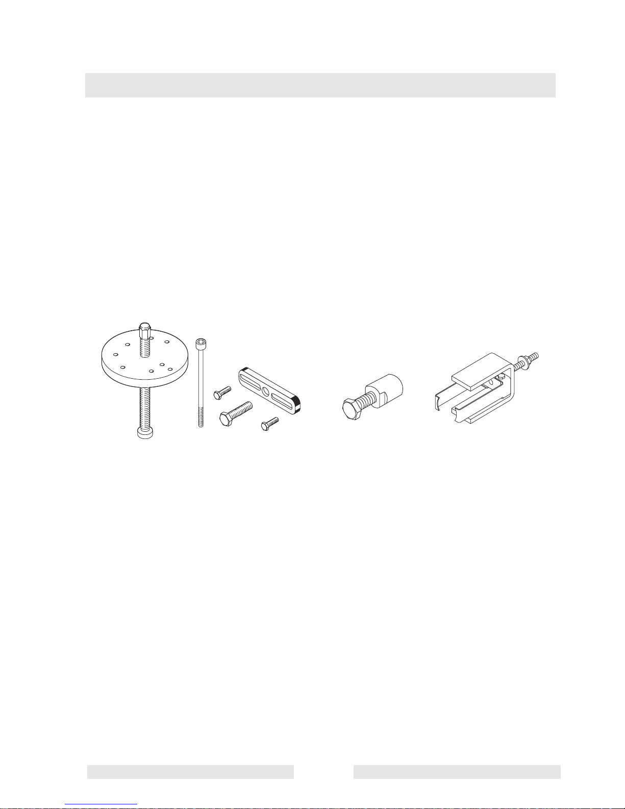
2.1 Recommended Special Tools
See Graphic: wc_gr001305rm
P/N 0081423 Spring box tool
P/N 0117972 Clutch puller
P/N 0153566 Clutch puller (DS 70 only)
P/N 0116816 Impact bushing puller
0081423
0117972
0116816
wc_gr001305rm
0153566
Page 18

Tools Rammer Repair
wc_tx001544gb.fm 18
2.2 Recommended Repair Tools
Hex key or socket: 4 mm, 5 mm, 6 mm, 8 mm
Ratchet wrench
Extension
Sockets: 10 mm, 13 mm, 17 mm, 19 mm (3/4”), 24 mm,
27 mm (1-1/16”), 32 mm, 38 mm (1-1/2”)
Open-end wrench: 13 mm
Screwdriver
Needle-nose pliers
Large-diameter retaining-ring pliers
Rubber mallet
Punch
Bearing puller
Slide hammer
Drift pin
Impact wrench
Torque wrench (up to 210 Nm [155 ft.lbs.])
Loctite 243
Shell Alvania RL 2 (No. 2) grease
Hydraulic press
Two threaded rods M8 x 120 mm and nuts
Split puller
Source of compressed air
Page 19
Rammer Repair Maintenance Schedules
wc_tx001545gb.fm 19
3 Maintenance Schedules
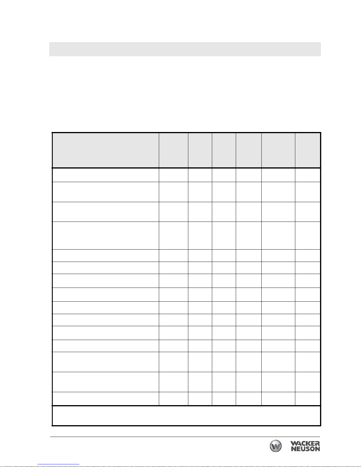
3.1 Periodic Maintenance Schedule (BS 50/60/70-2, BS 65)
The table below lists basic machine maintenance. Tasks designated
with check marks may be performed by the operator. Tasks
designated with square bullet points require special training and
equipment.
Daily
before
starting
After
first
5
hours
Every
week
or 25
hours
Every
month
or 100
hours
Every
3 months
or 300
hours
Every
Year
Check fuel level.
3
Check air filter indicator. Replace
as needed.
3
Check ramming system oil level in
sightglass.
3
Check fuel line and fittings for
cracks or leaks. Replace as
needed.
Tighten ramming shoe hardware.
Check engine cylinder screws.
Check external hardware.
33
Clean engine cooling fins.
3
Clean and check spark plug gap.
Replace spark plug.
Clean recoil starter.
3
Change ramming system oil.*
Clean engine muffler and exhaust
port.
Inspect lifting cable for wear,
damage, or abuse.
3
Inspect fuel filter.
3
* Change ramming system oil after first 50 hours of operation.
Note: If engine performance is poor, check, clean, and replace air filter elements as needed.
Page 20
Maintenance Schedules Rammer Repair
20 wc_tx001545gb.fm
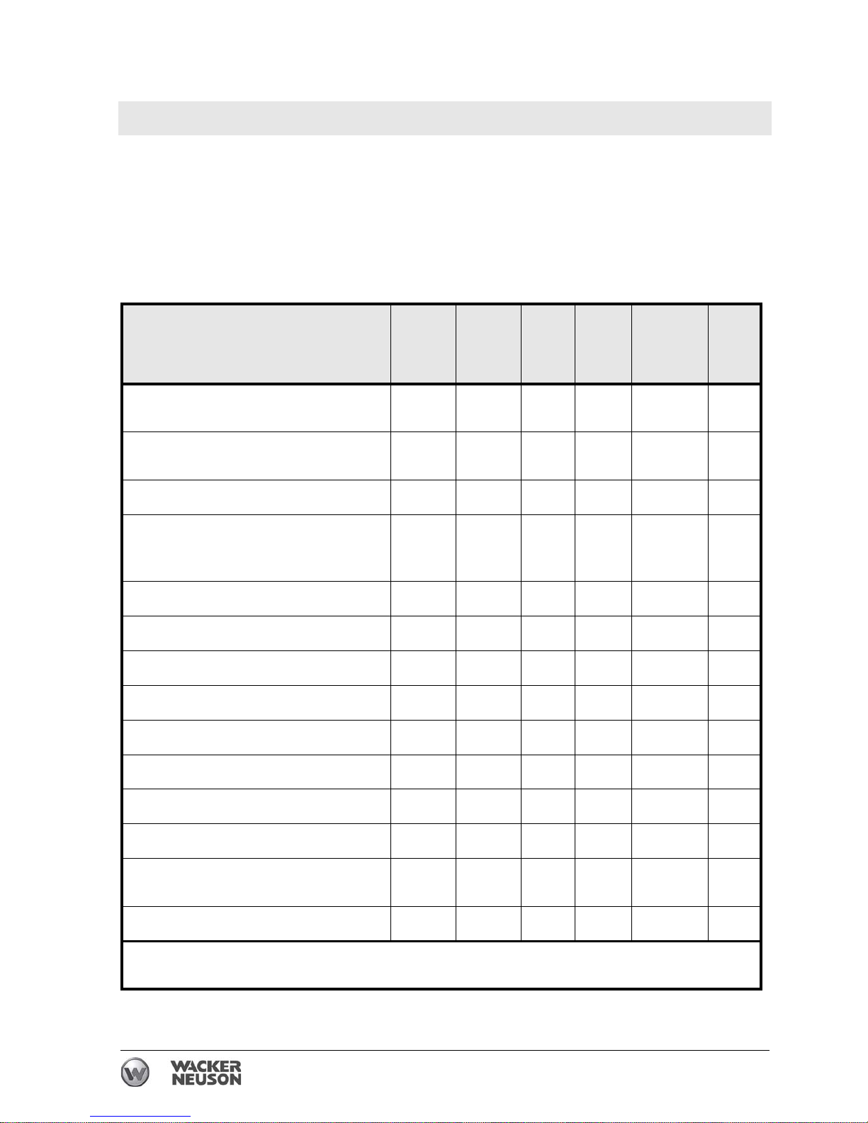
3.2 Periodic Maintenance Schedule (BS 500/600/700/650)
The table below lists basic machine maintenance. Tasks designated
with check marks may be performed by the operator. Tasks
designated with square bullet points require special training and
equipment.
Daily
before
starting
After
first
5 hours
Every
week
or 25
hours
Every
month
or 100
hours
Every
3 months
or 300
hours
Every
Year
Check fuel level. Check engine oil
level.
3
Inspect air filter. Replace as
needed.
3
Check oil level in sightglass.
3
Check fuel line and fittings for
cracks or leaks. Replace as
needed.
Tighten ramming shoe hardware.
Check external hardware.
33
Clean engine cooling fins.
3
Clean and check spark plug gap.
Change engine oil.
Replace spark plug.
Clean recoil starter.
3
Change ramming system oil.*
Inspect lifting cable on rammer for
wear, damage, or abuse.
3
Inspect fuel filter.
3
* Change ramming system oil after first 50 hours of operation.
Note: If engine performance is poor, check, clean, and replace air filter elements as needed.
Page 21
Rammer Repair Maintenance Schedules
wc_tx001545gb.fm 21
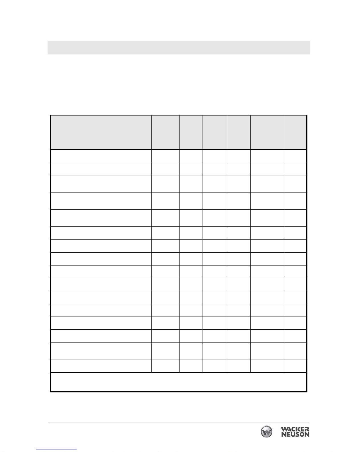
3.3 Periodic Maintenance Schedule (BS 50/60/70-2i)
The table below lists basic machine maintenance. Tasks designated
with check marks may be performed by the operator. Tasks
designated with square bullet points require special training and
equipment.
Daily
before
starting
After
first
5
hours
Every
week
or 25
hours
Every
month
or 100
hours
Every
3 months
or 300
hours
Every
Year
Check fuel level.
3
Check engine oil level.
3
Check air filter indicator. Replace as
needed.
3
Check ramming system oil level in
sightglass.
3
Check fuel line and fittings for cracks or
leaks. Replace as needed.
Tighten ramming shoe hardware.
Check engine cylinder screws.
Check external hardware.
33
Clean engine cooling fins.
3
Clean and check spark plug gap.
Replace spark plug.
Clean recoil starter.
3
Change ramming system oil.*
Clean engine muffler and exhaust port.
Inspect lifting cable for wear, damage,
or abuse.
Inspect fuel filter.
3
* Change ramming system oil after first 50 hours of operation.
Note: If engine performance is poor, check, clean, and replace air filter elements as needed.
Page 22
Maintenance Schedules Rammer Repair
22 wc_tx001545gb.fm
3.4 Periodic Maintenance Schedule (BS 500/600/700-oi)
The table below lists basic machine maintenance. Tasks designated
with check marks may be performed by the operator. Tasks
designated with square bullet points require special training and
equipment.
Daily
before
starting
After
first
5
hours
Every
week
or 25
hours
Every
month
or 100
hours
Every
3 months
or 300
hours
Every
Year
Check fuel level.
Inspect air filter. Replace as
needed.
Check engine oil level.
Check ramming system oil level
in sightglass.
Check fuel line and fittings for
cracks or leaks.
Tighten ramming shoe hardware.
Check engine cylinder screws.
Check external hardware.
Clean engine cooling fins.
Clean and check spark plug gap.
Replace spark plug.
Clean recoil starter.
Change ramming system oil.*
Clean engine muffler and
exhaust port.
Inspect crane lifting cable for
wear, damage, or abuse.
Inspect fuel filter. Inspect oil filter.
* Change ramming system oil after first 50 hours of operation.
Note: If engine performance is poor, check, clean, and replace air filter elements as needed.
Page 23
Rammer Repair Maintenance Schedules
wc_tx001545gb.fm 23
3.5 Periodic Maintenance Schedule (DS 70)
Daily
before
starting
After
first
5
hours
Every
week
or
25 hours
Every
month
or
100 hours
Every 3
months or
300 hours
Every 5
months or
500 hours
Check fuel level.
3
Check engine oil level.
3
Check air filter indicator.
Replace as needed.
3
Check rammer oil level in
sightglass.
3
Check fuel line, cap and
fittings for cracks or leaks.
Replace as needed.
3
Check bellows for damage and fit.
3
Tighten ramming shoe
hardware.
Check external hardware.
33
Clean engine cooling fins.
3
Change engine oil.*
Clean engine oil filter.*
Clean recoil starter.
Change ramming system
oil.*
Inspect lifting cable for
wear, damage, or abuse.
Check and adjust valve
clearance. **
Replace engine oil filter.
Check fuel filter, clean or
replace.
* Perform initially after first 50 hours of operation.
Note: If engine performance is poor, check, clean, and replace air filter elements as needed.
** Perform initially after first 25 hours of operation.
Page 24
Maintenance Schedules Rammer Repair
24 wc_tx001545gb.fm
3.6 Periodic Maintenance Schedule (DS 720)
The table below lists basic machine maintenance. Tasks designated
with check marks may be performed by the operator. Tasks
designated with square bullet points require special training and
equipment.
Daily
before
starting
After
first
5
hours
Every
week
or
25 hours
Every
month
or
100 hours
Every 3
months or
300 hours
Every 5
months or
500 hours
Check fuel level.
Check engine oil level.
Check rammer oil level in
sightglass.
Check fuel line, cap and
fittings for cracks or leaks.
Check bellows for damage
and fit.
Tighten ramming shoe
hardware.
Check external hardware.
Clean engine cooling fins.
Change engine oil.*
Clean engine oil filter.*
Clean recoil starter.
Change ramming system
oil.*
Inspect crane lifting cable for
wear, damage, or abuse.
Check and adjust valve
clearance.**
Replace engine oil filter.
Check fuel filter, clean or
replace.
* Perform initially after first 50 hours of operation.
** Perform initially after first 25 hours of operation.
Note: If engine performance is poor, check, clean, and replace air filter elements as needed.
Page 25
Rammer Repair Engine and Upper Machine Components
wc_tx001546gb.fm 25
4 Engine and Upper Machine Components
4.1 Removing the Silencing Cover
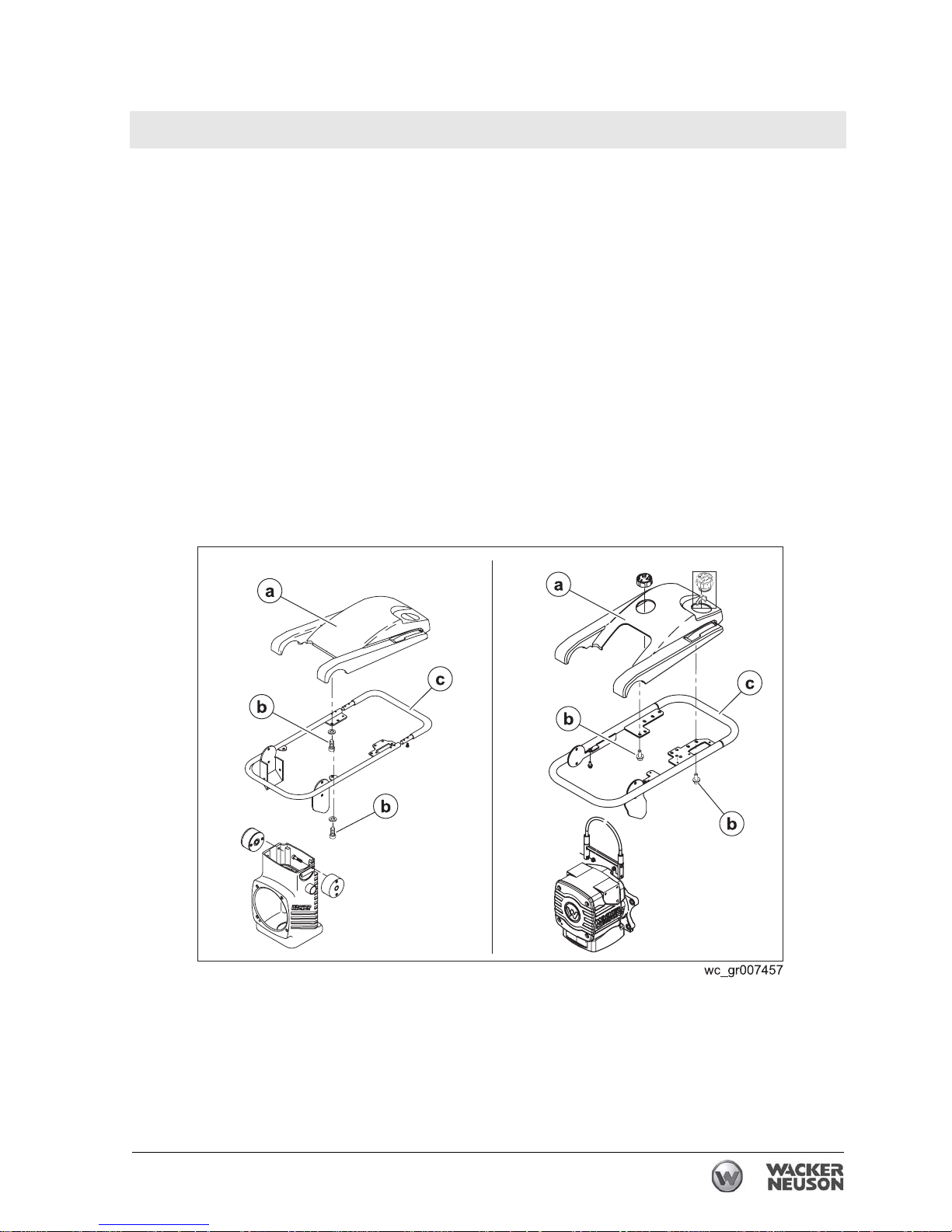
See Graphic: wc_gr007457
Recommended Tools
Ratchet Wrench
Torque Wrench
Hex Key or Hex Socket: 5 mm
Loctite 243 (Blue)
Remove the four socket head cap screws (b) that hold the silencing
cover (a) to the guide handle (c). When reinstalling the silencing cover,
apply Loctite 243 and torque the screws to 9.4 Nm (6.9 ft.lbs.).
Page 26
Engine and Upper Machine Components Rammer Repair
26 wc_tx001546gb.fm
4.2 Replacing the Throttle Control (2010 and later 2-stroke models)
Requirements
• Machine shut down and cool
• Torque wrench
Removal
Perform the procedure below to remove the throttle control.
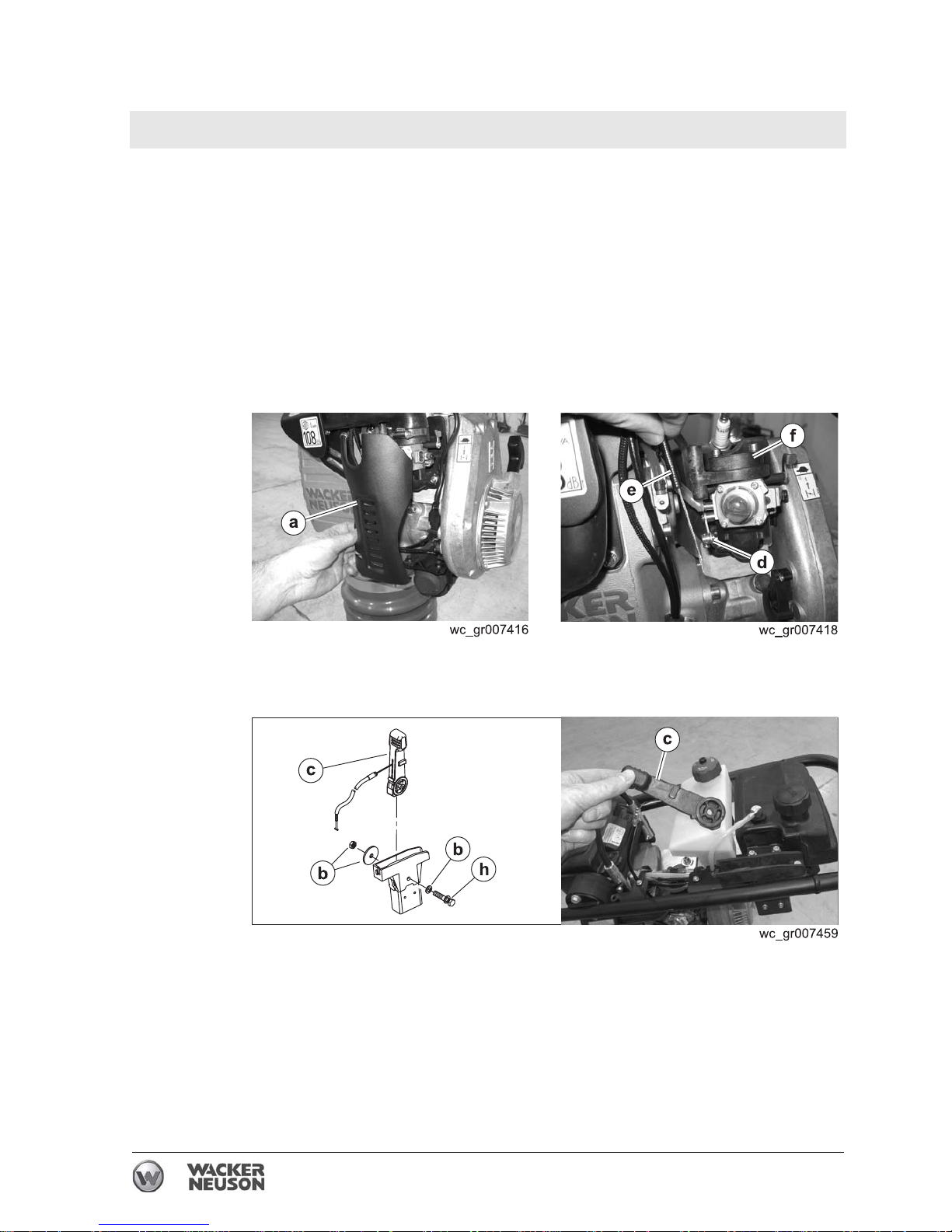
4.2.1 Remove the silencing cover. See topic Removing the Silencing Cover.
4.2.2 Remove the carburetor guard (a).
4.2.3 Loosen the swivel (d) and slide the throttle cable and casing (e) from
the carburetor adapter (f).
4.2.4 Remove the bolt (h) and hardware (b).
4.2.5 Remove the throttle control
(c) from the machine.
Result
The throttle control has now been removed.
Page 27
Rammer Repair Engine and Upper Machine Components
wc_tx001546gb.fm 27
Installation
Perform the procedure below to install the throttle control.
4.2.1 Connect the throttle control (c) to the machine with bolt (h) and
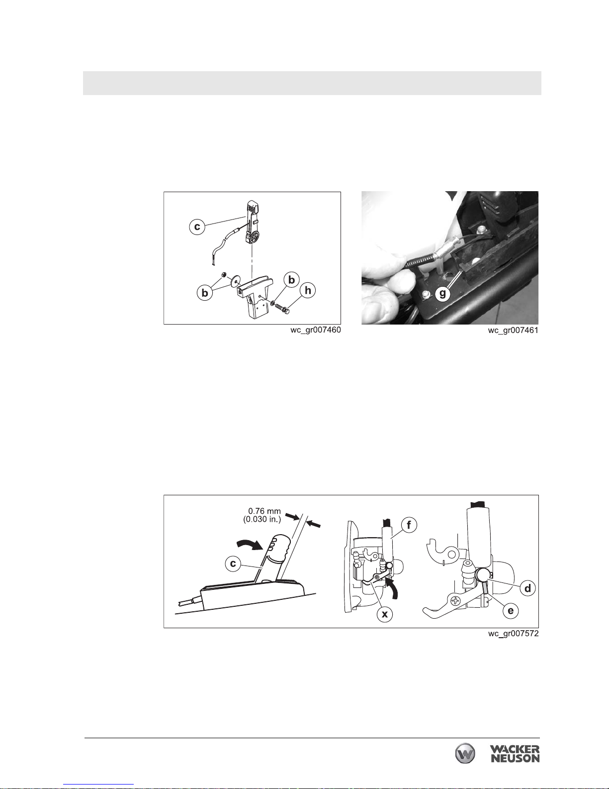
hardware (b). Adjust the nut on the throttle control lever so that the
lever moves freely but still holds its position while the rammer is
operating. The recommended torque value is 2.9 Nm (2.1 ft.lbs.).
4.2.2 Connect the throttle cable to the machine at point (g).
4.2.3 Connect the throttle cable to the carburetor. To do so:
a. Place the throttle control (c) in the full throttle position with a 0.76
mm (0.030 in.) feeler gauge between the throttle control and the
machine.
b. Rotate the throttle lever (x) so that it is tight against the carburetor
adapter (f).
c. Thread the throttle cable (e) through the carburetor adapter and
through the swivel (d). Pull the throttle cable taught, then tighten the
swivel screw.
d. Release the throttle lever.
4.2.4 Install the carburetor guard
(a). Torque the screws to 23 Nm (16 ft.lbs.)
Result
The replacement procedure is now complete.
Page 28
Engine and Upper Machine Components Rammer Repair
28 wc_tx001546gb.fm
4.3 Replacing the Throttle Control (2010 4-stroke models)
Requirements
• Machine shut down and cool
• Torque wrench
Removal
Perform the procedure below to remove the throttle control.
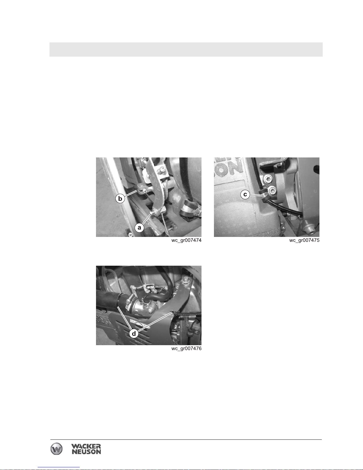
4.3.1 Remove the silencing cover. See topic Removing the Silencing Cover.
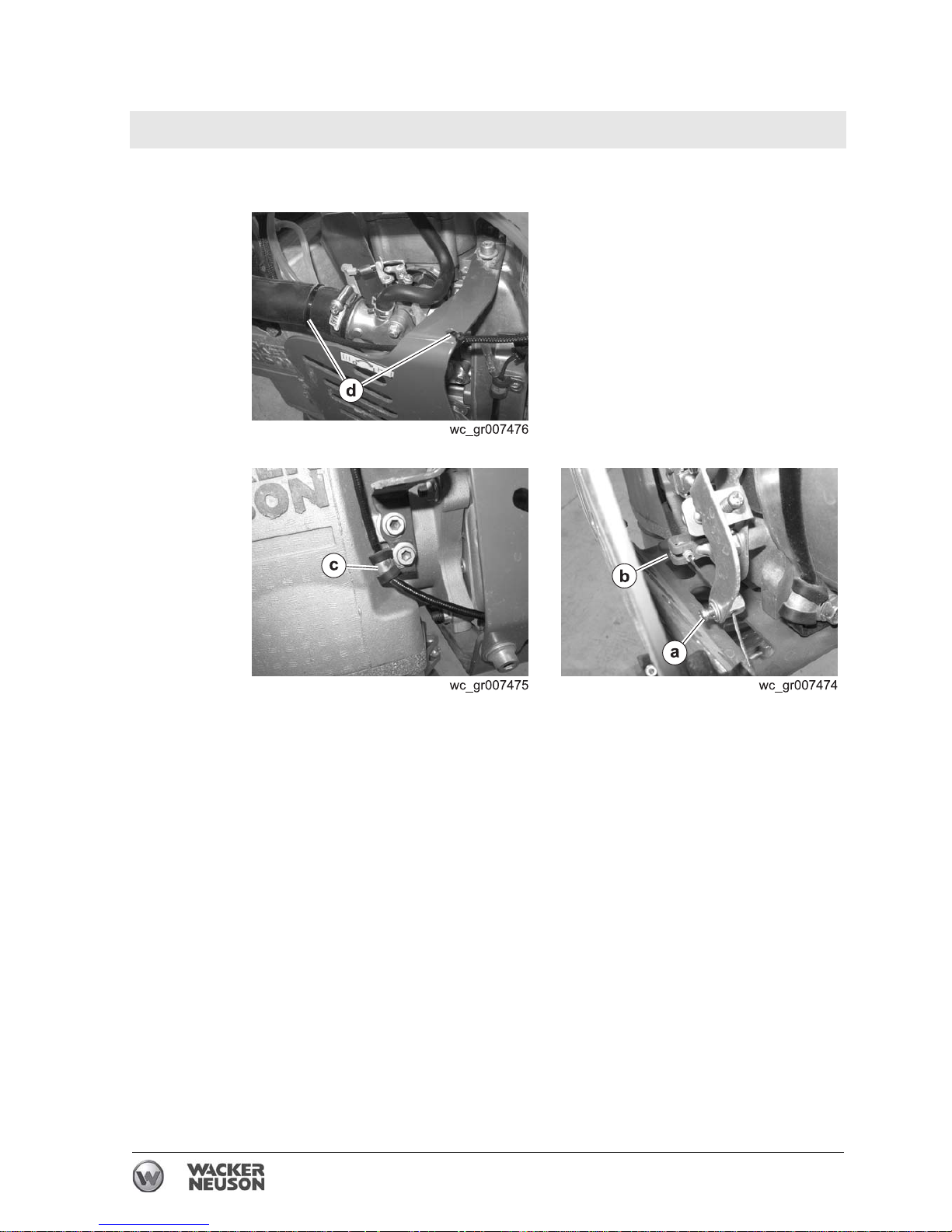
4.3.2 Disconnect the throttle cable at the swivel (a) and the clamp (b).
4.3.3 Remove the clamp (c).
4.3.4 Clip the wire ties (d).
This procedure continues on the next page.
Page 29
Rammer Repair Engine and Upper Machine Components
wc_tx001546gb.fm 29
Continued from the previous page.
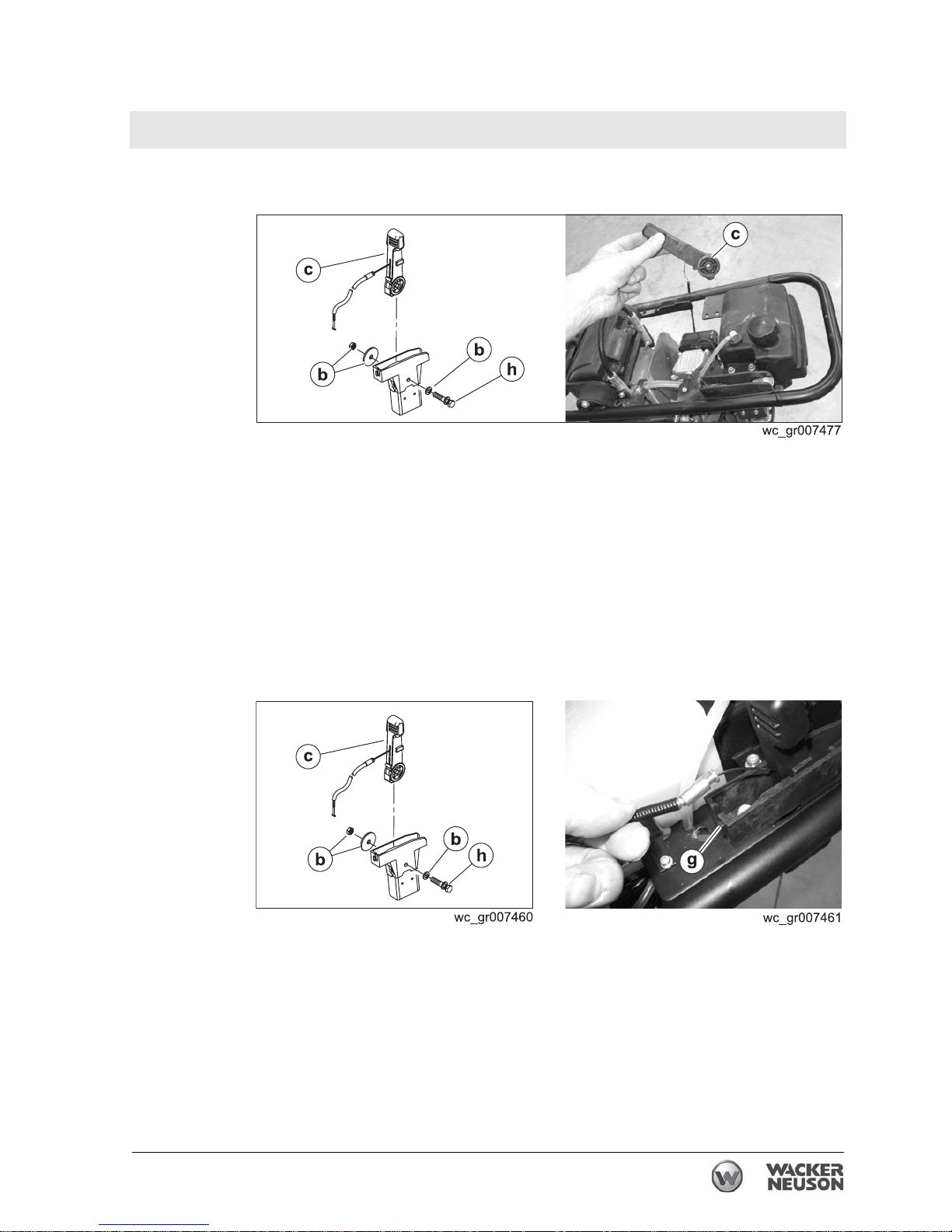
4.3.5 Remove the bolt (h) and hardware (b).
4.3.6 Remove the throttle lever (c) from the machine.
Result
The removal procedure is now complete.
Installation
Perform the procedure below to install the throttle control.
4.3.1 Connect the throttle lever (c) to the machine with bolt (h) and
hardware (b). Adjust the nut on the throttle control lever so that the
lever moves freely but still holds its position while the rammer is
operating. The recommended torque value is 2.9 Nm (2.1 ft.lbs.).
4.3.2 Connect the throttle cable to the machine at point
(g).
This procedure continues on the next page.
Page 30
Engine and Upper Machine Components Rammer Repair
30 wc_tx001546gb.fm
Continued from the previous page.
4.3.3 Support the throttle cable with new wire ties (d).
4.3.4 Install the clamp (c).
4.3.5 Connect the throttle cable at the swivel (a) and the clamp (b).
4.3.6 Reinstall the silencing cover.
Result
The replacement procedure is now complete.
Page 31
Rammer Repair Engine and Upper Machine Components
wc_tx001546gb.fm 31
4.4 Throttle Control (pre-2010 models)
See Graphic: wc_gr003876
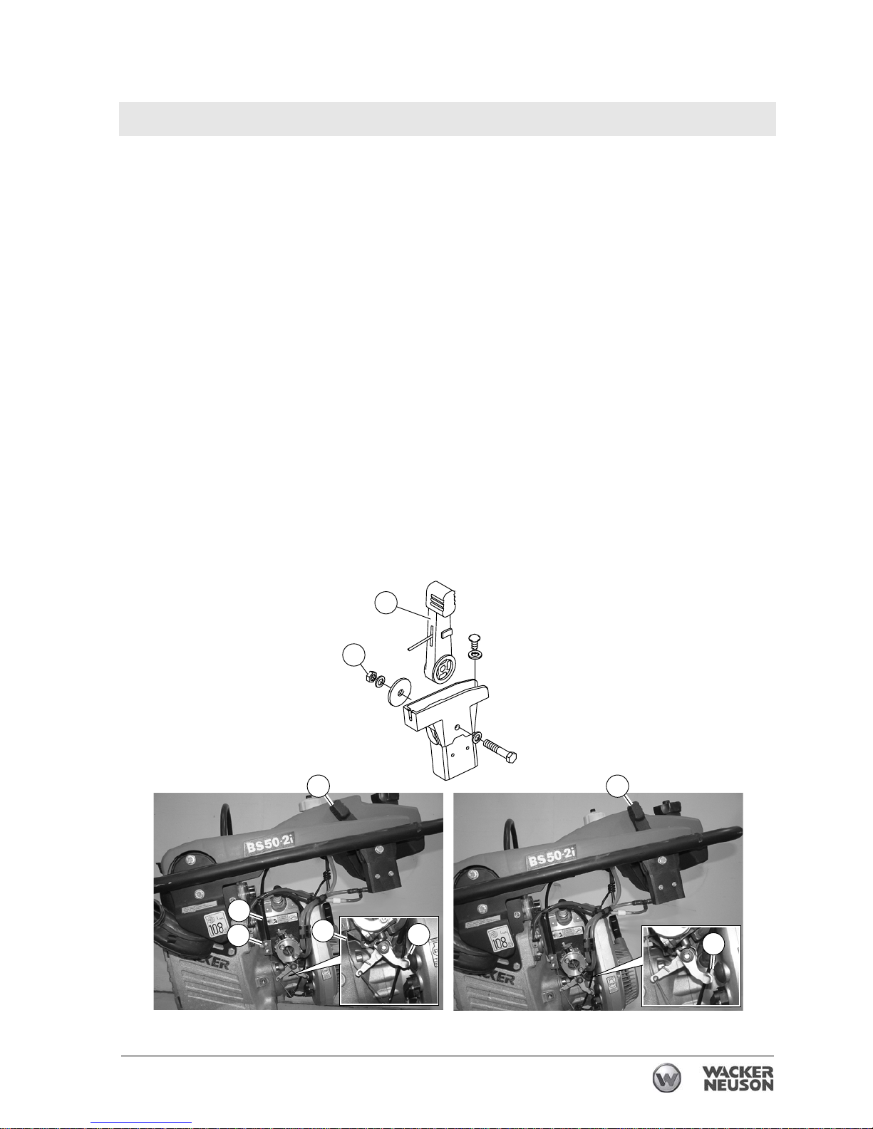
4.4.1 Adjust the nut (a) on the throttle control lever (b) so that the lever
moves freely but still holds its position while the rammer is operating.
The recommended torque value is 2.9 Nm (2.1 ft.lbs.).
To adjust the throttle cable:
4.4.2 Place the throttle lever in the STOP position (c).
4.4.3 Loosen the clamp screws (d).
4.4.4 Slide the throttle cable (e) through the clamp until there is slack (f) in
the throttle cable and the stop lever activates the stop button (g).
4.4.5 Tighten the clamp screws.
4.4.6 Place the throttle control in the IDLE position (h).
4.4.7 Check that the stop button is not activated. There should be a gap (i)
between the stop lever and the stop button.
4.4.8 Adjust the cable at the clamp as necessary so that the engine stops
when the throttle control is in the STOP position and idles when the
throttle control is in the IDLE position.
wc_gr003876
c
a
b
h
d
f
g
i
e
Page 32
Engine and Upper Machine Components Rammer Repair
32 wc_tx001546gb.fm
4.5 Replacing the Stop Switch (2010 and later 2-stroke models)
Requirements
• Machine shut down and cool
• Torque wrench
Removal
Perform the procedure below to remove the stop switch.
4.5.1 Remove the silencing cover. See topic Replacing the Silencing Cover.
4.5.2 Remove the throttle control. See topic Replacing the Throttle Control.
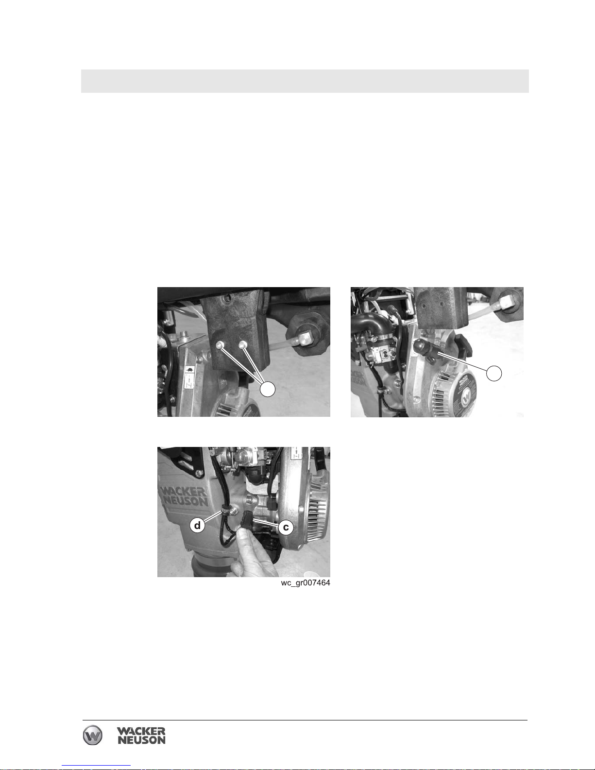
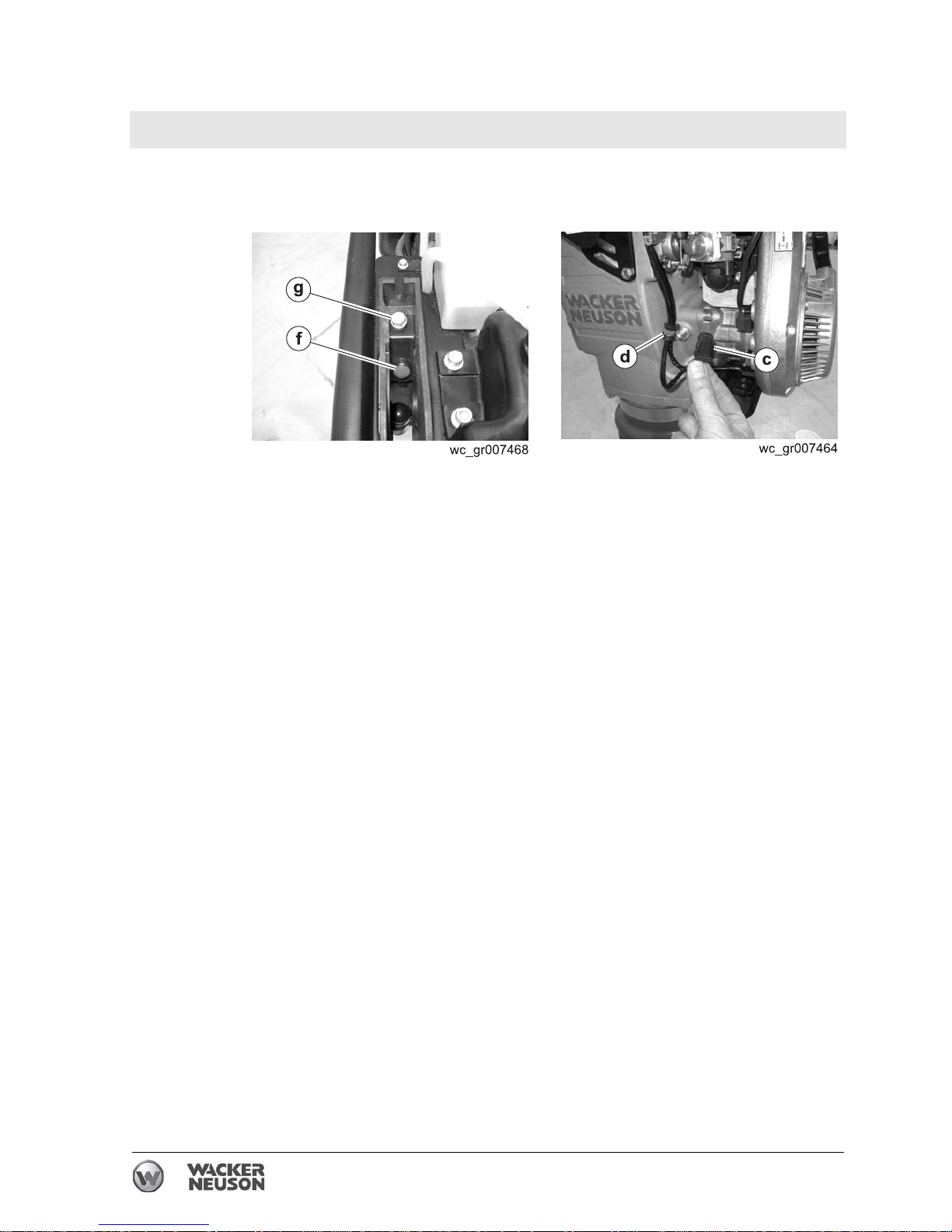
4.5.3 Remove the two screws (a) the hold the fuel valve to the throttle
control bracket. Allow the fuel valve (b) to hang by the fuel hoses.
4.5.4 Disconnect the stop switch wiring (c) from the engine.
4.5.5 Remove the clamp
(d).
This procedure continues on the next page.
wc_gr007463
a
wc_gr007462
b
Page 33
Rammer Repair Engine and Upper Machine Components
wc_tx001546gb.fm 33
Continued from the previous page.
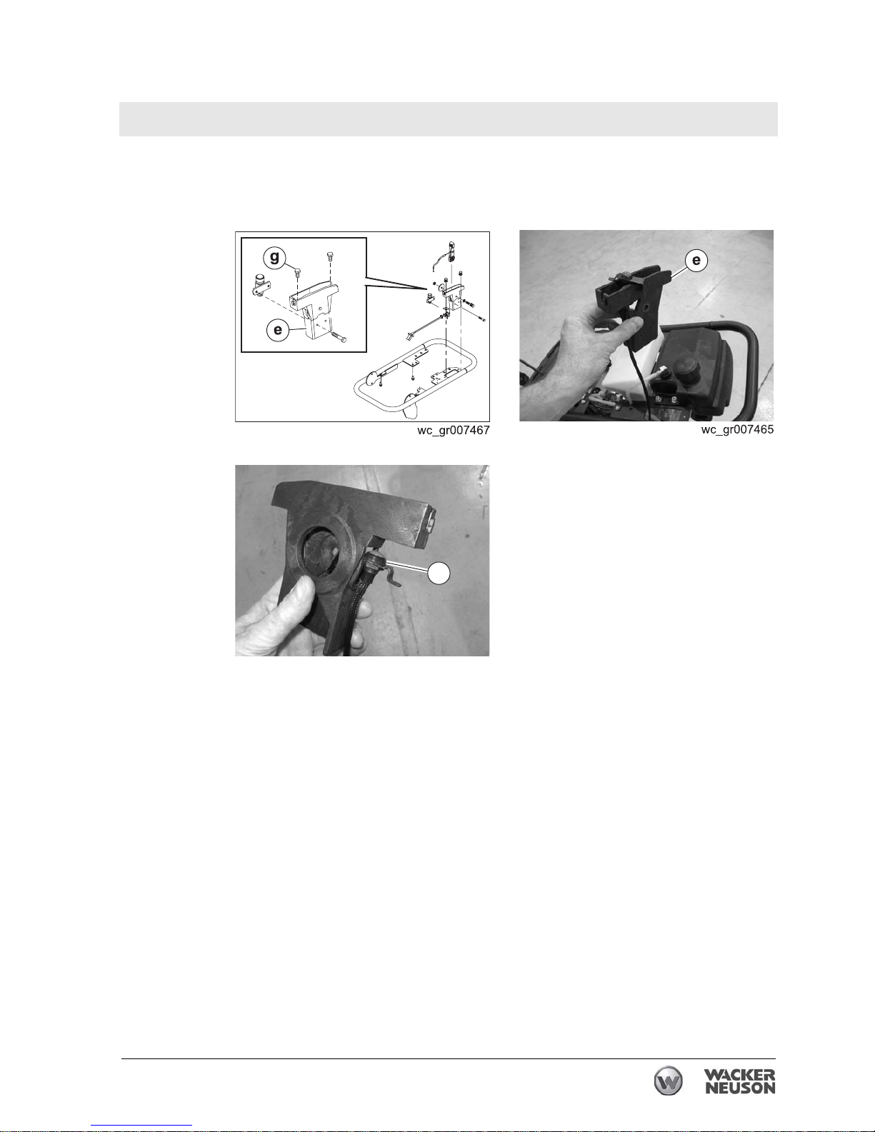
4.5.6 Remove the screws (g) that hold the throttle control bracket to the
machine and pull the throttle control bracket (e) (with stop switch) from
the machine.
4.5.7 Pull the stop switch (f) and wiring from the throttle control bracket.
Result
The removal procedure is now complete.
Installation
Perform the procedure below to install the stop switch.
4.5.1 Slide the stop switch (f) into the throttle control bracket (e) and thread
the wiring through the throttle control bracket.
This procedure continues on the next page.
wc_gr007466
f
Page 34
Engine and Upper Machine Components Rammer Repair
34 wc_tx001546gb.fm
Continued from the previous page.
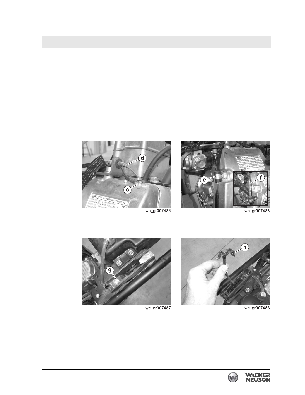
4.5.2 Install the throttle control bracket and the stop switch (f) with screws
(g).Torque the screws to 10 Nm (7 ft.lbs.).
4.5.3 Reconnect the stop switch wiring (c) to the engine.
4.5.4 Reinstall the clamp (d).
4.5.5 Reinstall the throttle control.
4.5.6 Reinstall the silencing cover.
Result
The replacement procedure is now complete.
Page 35
Rammer Repair Engine and Upper Machine Components
wc_tx001546gb.fm 35
4.6 Replacing the Stop Switch (2010 and later 4-stroke models)
Requirements
• Machine shut down and cool
• Torque wrench
Removal
Perform the procedure below to remove the stop switch.
4.6.1 Remove the silencing cover. See topic Replacing the Silencing Cover.
4.6.2 Remove the throttle control. See topic Replacing the Throttle Control.
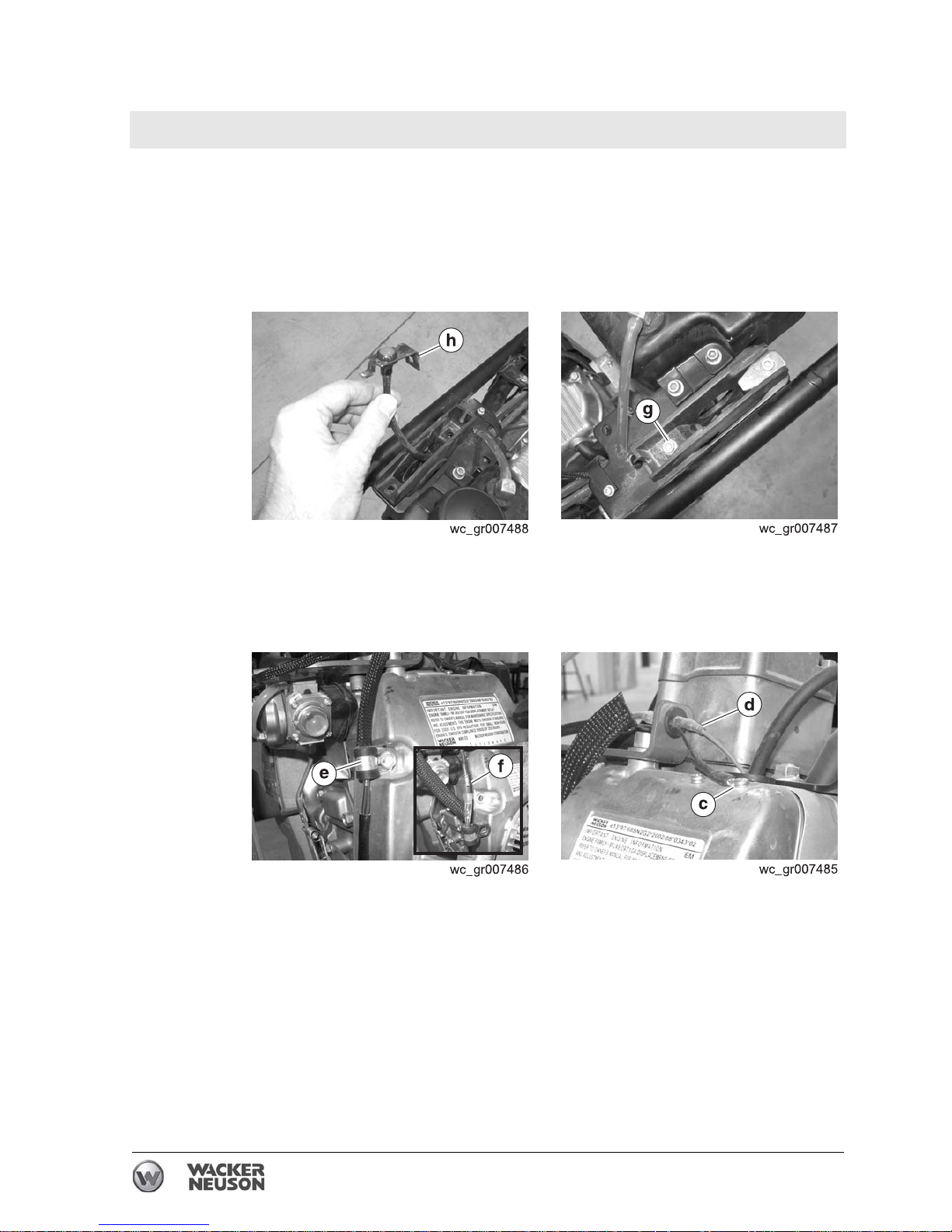
4.6.3 Disconnect the wiring (c and d) from the engine.
4.6.4 Remove the clamp (e). Disconnect the wiring connector (f).
4.6.5 Remove the screw (g) that holds the stop switch and remove the stop
switch (h) from the throttle control bracket.
Result
The removal procedure is now complete.
This procedure continues on the next page.
Page 36
Engine and Upper Machine Components Rammer Repair
36 wc_tx001546gb.fm
Continued from the previous page.
Installation
Perform the procedure below to install the stop switch.
4.6.1 Slide the stop switch
(h) into the throttle control bracket and thread the
wiring through the throttle control bracket.
4.6.2 Install the stop switch to the machine with screw (g). Torque the screw
to 9 Nm (6 ft.lbs.).
4.6.3 Reconnect the wiring connector (f). Apply Loctite 243® to the screw
holding the clamp (e) and reinstall the clamp (e). Torque the screw to
25 Nm (18 ft.lbs.).
4.6.4 Reconnect the wiring
(c and d) to the engine.
Result
The procedure to replace the stop switch is now complete.
Page 37
Rammer Repair Engine and Upper Machine Components
wc_tx001546gb.fm 37
4.7 Replacing the Guide Handle (2010 and later 2-stroke models)
Requirements
• Machine shut down and cool
• Loctite® 243
Removal
Perform the procedure below to remove the guide handle.
4.7.1 Remove the silencing cover. See topic Replacing the Silencing Cover.
4.7.2 Remove the throttle control. See topic Replacing the Throttle Control.
4.7.3 Remove the throttle control bracket. See topic Replacing the Stop
Switch
.
4.7.4 Drain the fuel tank (optional).
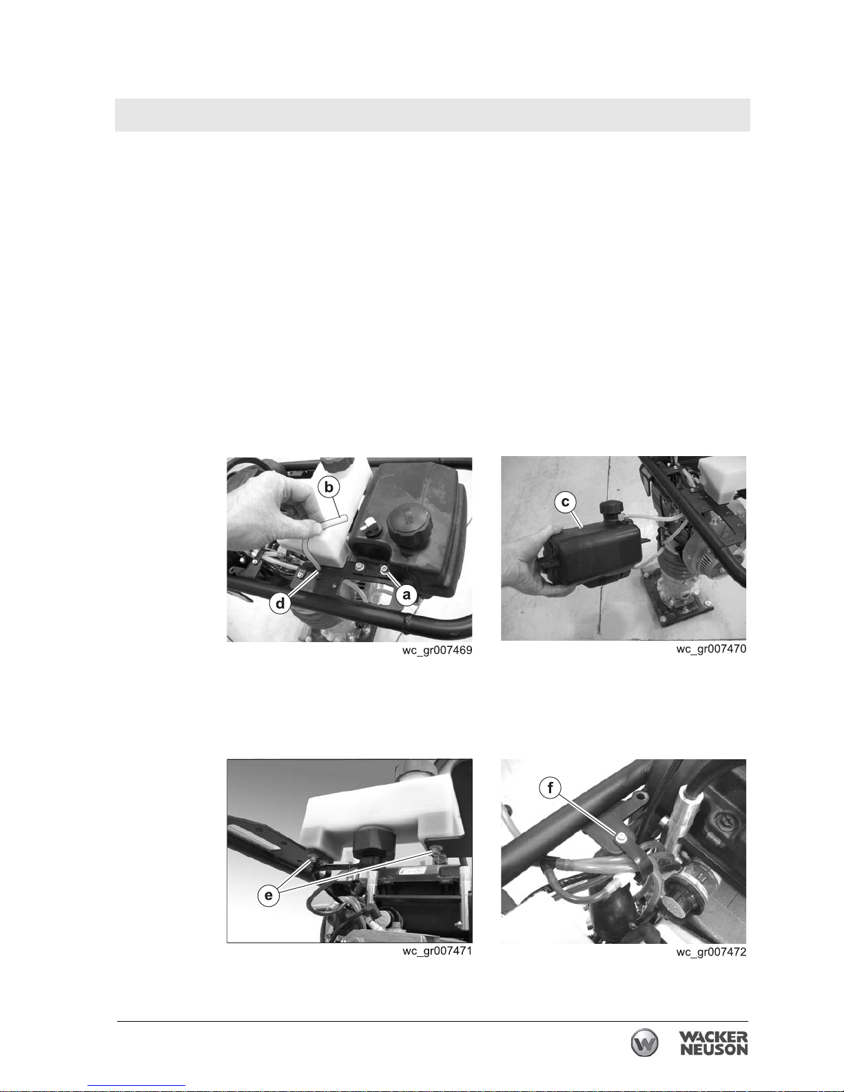
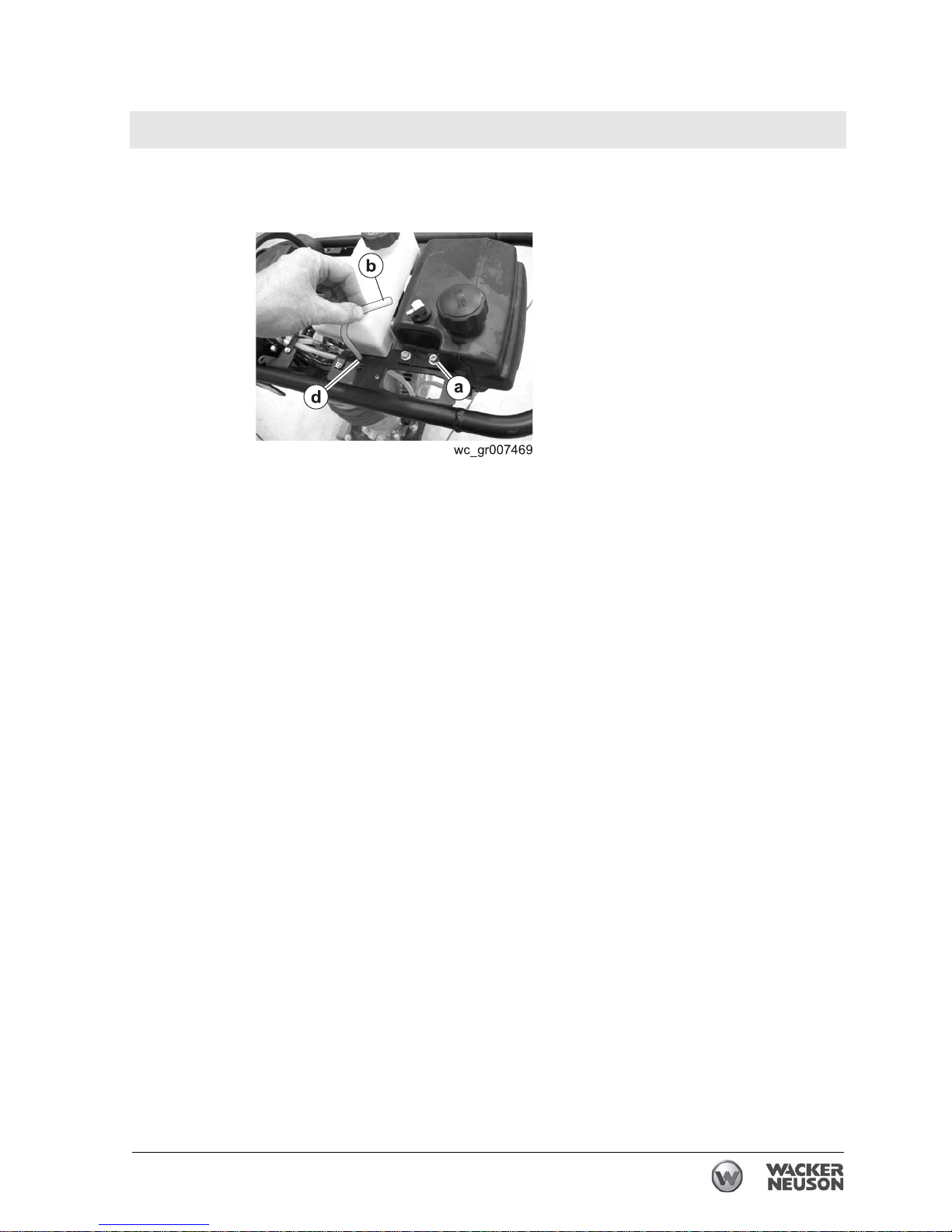
4.7.5 Remove the screws (a) that hold the fuel tank to the guide handle.
4.7.6 Disconnect the upper fuel line (b) from the tank. Thread the fuel line
through the hole in the guide handle (d), then reconnect it to the fuel
tank
(c). Place the fuel tank on top of engine.
4.7.7 On machines with oil tanks, remove the screws (e) that hold the oil
tank to the guide handle and place the oil tank on top of the engine.
4.7.8 Remove the oil hose and the fuel hose from the clips (f) on the
handles.
This procedure continues on the next page.
Page 38
Engine and Upper Machine Components Rammer Repair
38 wc_tx001546gb.fm
Continued from the previous page.
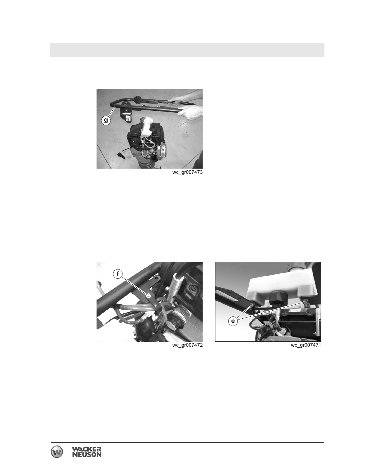
4.7.9 Remove the screws that hold the guide handle (g) to the shock
mounts and remove the guide handle from the machine.
Result
The removal procedure is now complete.
Installation
Perform the procedure below to install the guide handle.
4.7.1 Install the guide handle to the shock mounts. Use Loctite® 243 on the
screws and torque the screws to 24 Nm (18 ft.lbs.).
4.7.2 Feed the hoses through the clips (f).
4.7.3 Install the oil tank to the guide handle using the screws (e). Torque the
screws to 9 Nm (6 ft.lbs.).
This procedure continues on the next page.
Page 39
Rammer Repair Engine and Upper Machine Components
wc_tx001546gb.fm 39
Continued from the previous page.
4.7.4 Thread the upper fuel line (b) through the hole (d) in the guide handle
and connect it to the fuel tank.
4.7.5 Install the fuel tank with screws (a). Torque the screws to 9 Nm (6
ft.lbs.).
4.7.6 Install the throttle control bracket. See topic Replacing the Stop Switch.
4.7.7 Install the throttle control. See topic Replacing the Throttle Control.
4.7.8 Install the silencing cover. See topic Replacing the Silencing Cover.
Result
The replacement procedure is now complete.
Page 40
Engine and Upper Machine Components Rammer Repair
40 wc_tx001546gb.fm
4.8 Replacing the Guide Handle (2010 and later 4-stroke models)
Requirements
• Machine shut down and cool
• Torque wrench
• Loctite® 243
Removal
Perform the procedure below to remove the guide handle.
4.8.1 Remove the silencing cover. See topic Replacing the Silencing Cover.
4.8.2 Remove the throttle control. See topic Replacing the Throttle Control.
4.8.3 Remove the stop switch. See topic Replacing the Stop Switch.
4.8.4 Drain the fuel tank (optional).
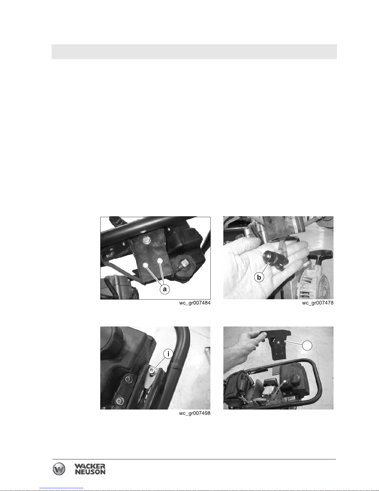
4.8.5 Remove the screws (a) that hold the fuel valve. Allow the fuel valve (b)
to hang freely.
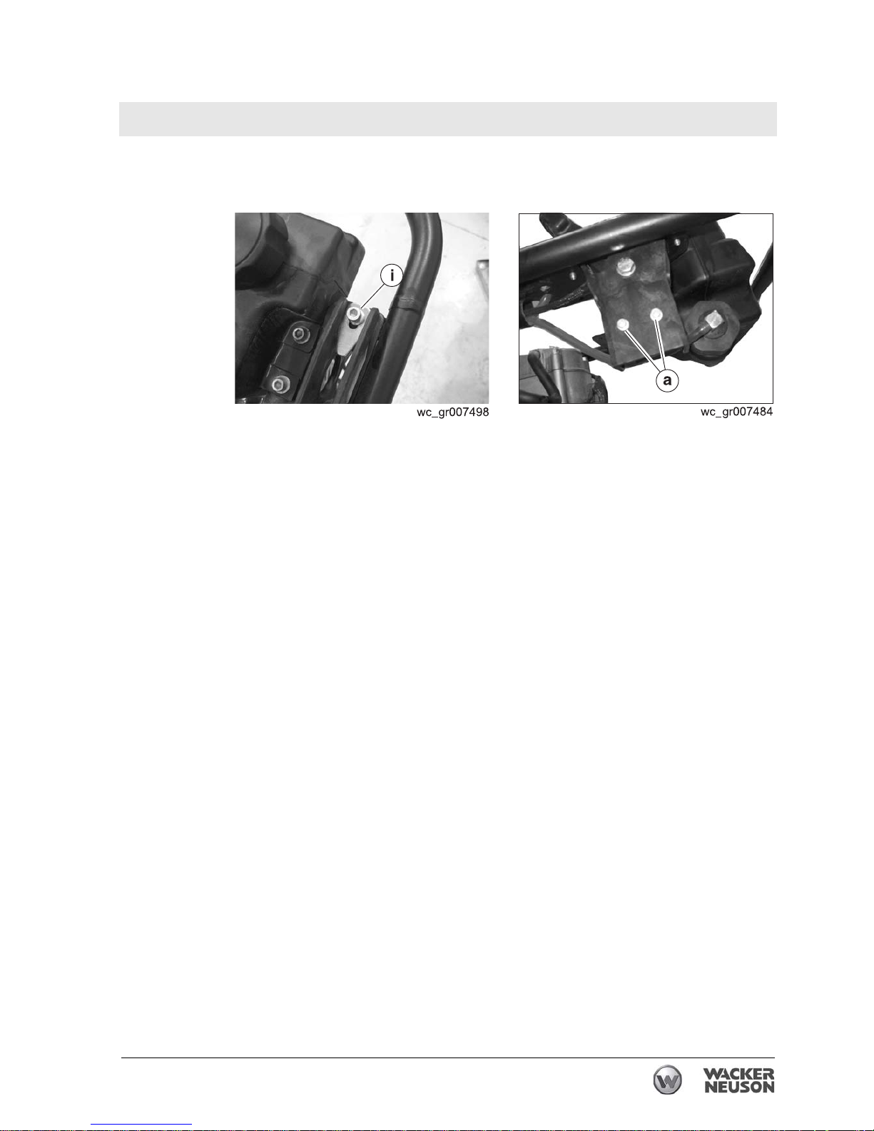
4.8.6 Remove the screw that holds the throttle stop (i) and remove the
throttle stop.
4.8.7 Remove the throttle control bracket (j).
This procedure continues on the next page.
wc_gr007499
a
1
j
Page 41
Rammer Repair Engine and Upper Machine Components
wc_tx001546gb.fm 41
Continued from the previous page.
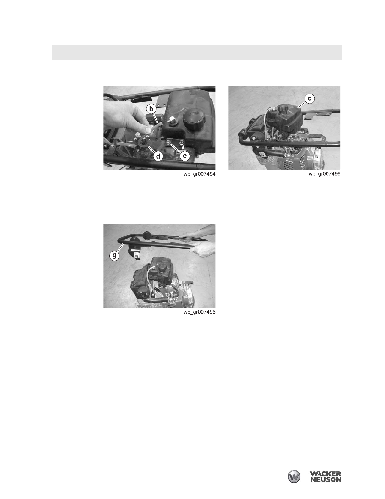
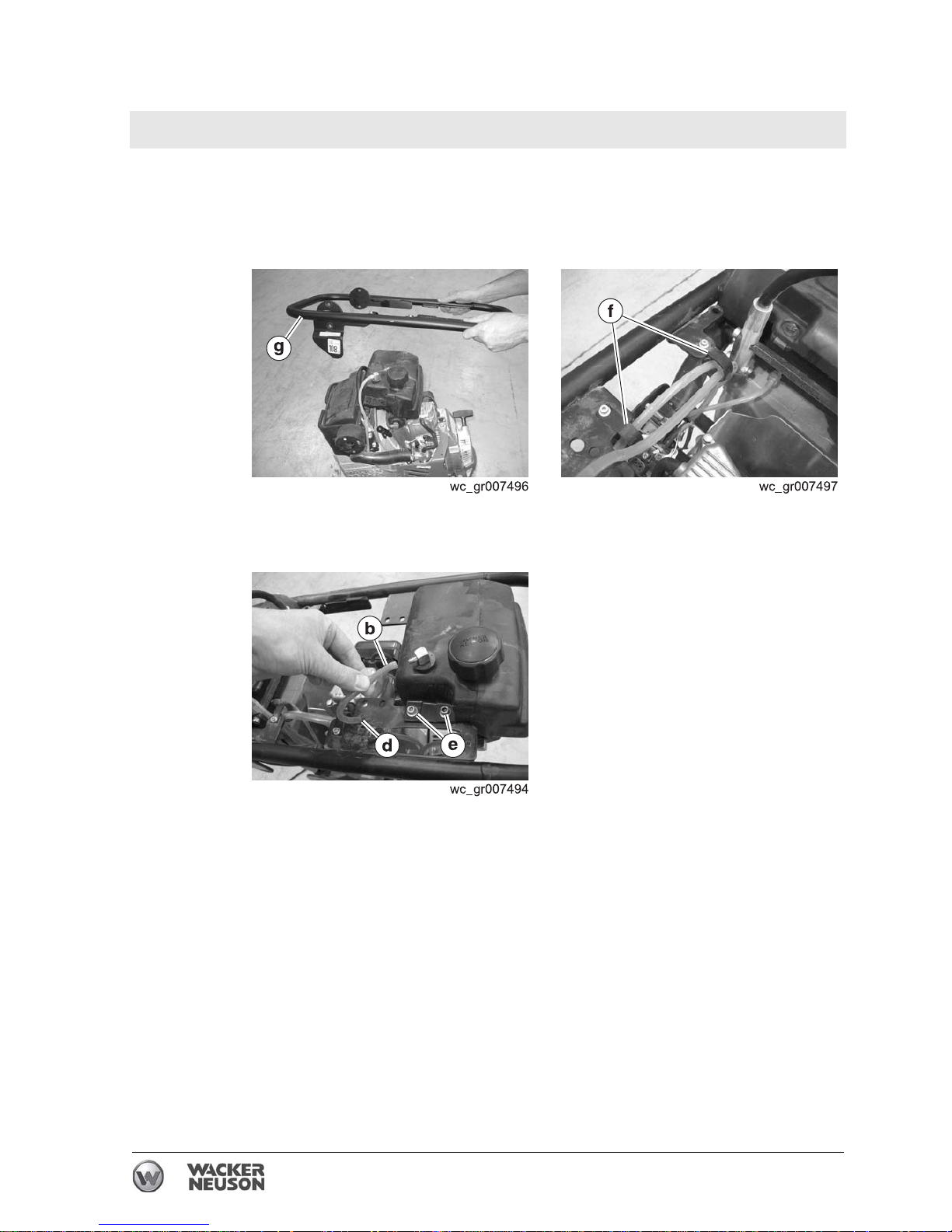
4.8.8 Remove the screws (e) that hold the fuel tank to the guide handle.
4.8.9 Disconnect the upper fuel line (b) from the tank. Thread the fuel line
through the hole in the guide handle (d), then reconnect it to the fuel
tank. Place the fuel tank (c) on top of engine.
4.8.10 Remove the screws that hold the guide handle (g) to the shock
mounts and remove the guide handle from the machine.
Result
The removal procedure is now complete.
Page 42
Engine and Upper Machine Components Rammer Repair
42 wc_tx001546gb.fm
Installation
Perform the procedure below to install the guide handle.
4.8.1 Install the guide handle (g) to the shock mounts. Use Loctite® 243 on
the screws and torque the screws to 24 Nm (18 ft.lbs.).
4.8.2 Feed the hoses through the clips (f).
4.8.3 Install the fuel tank to the guide handle with screws (e). Torque the
screws to 9 Nm (6 ft.lbs.).
4.8.4 Thread the upper fuel line
(b) through the hole in the guide handle (d),
then reconnect it to the fuel tank.
This procedure continues on the next page.
Page 43
Rammer Repair Engine and Upper Machine Components
wc_tx001546gb.fm 43
Continued from the previous page.
4.8.5 Install the throttle stop and the throttle control bracket with screw (i).
Torque the screw to 9 Nm (6 ft.lbs.).
4.8.6 Install the fuel valve with screws (a). Torque the screws to 3 Nm (2
ft.lbs.).
4.8.7 Install the stop switch. See topic Replacing the Stop Switch.
4.8.8 Install the throttle control. See topic Replacing the Throttle Control.
4.8.9 Install the silencing cover. See topic Replacing the Silencing Cover.
Result
The replacement procedure is now complete.
Page 44
Engine and Upper Machine Components Rammer Repair
44 wc_tx001546gb.fm
4.9 Replacing the Guide Handle (pre-2010 models)
See Graphic: wc_gr003704
Recommended Tools
Ratchet Wrench
Socket: 10 mm
Screwdriver
Pliers
Loctite 243 (Blue)
4.9.1 Close the fuel valve.
4.9.2 Disconnect the fuel line.
4.9.3 Loosen the throttle cable holder.
4.9.4 Disconnect the throttle cable from the throttle cam lever.
4.9.5 Remove the silencing cover.
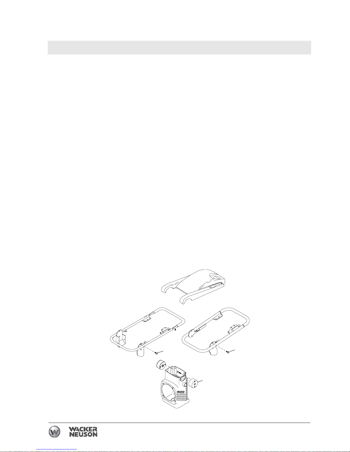
4.9.6 Remove the four hex head cap screws (d) that hold the guide handle
to the shock mounts (e). When reinstalling the guide handle, apply
Loctite 243 and torque the screws to 23 Nm (17 ft.lbs.).
4.9.7 Move the guide handle down and away from the shock mounts.
4.9.8 Lift the guide handle from the rammer.
Note: To inspect or change the shock mounts, it is not necessary to
disconnect the fuel line or the throttle cable.
a
wc_gr003704
a
b
Page 45
Rammer Repair Engine and Upper Machine Components
wc_tx001546gb.fm 45
4.10 Shock Mounts
See Graphic: wc_gr003705
Recommended Tools
Ratchet Wrench
Torque Wrench
Loctite 243 (blue)
4.10.1 Remove the silencing cover, the air cleaner, and the guide handle.
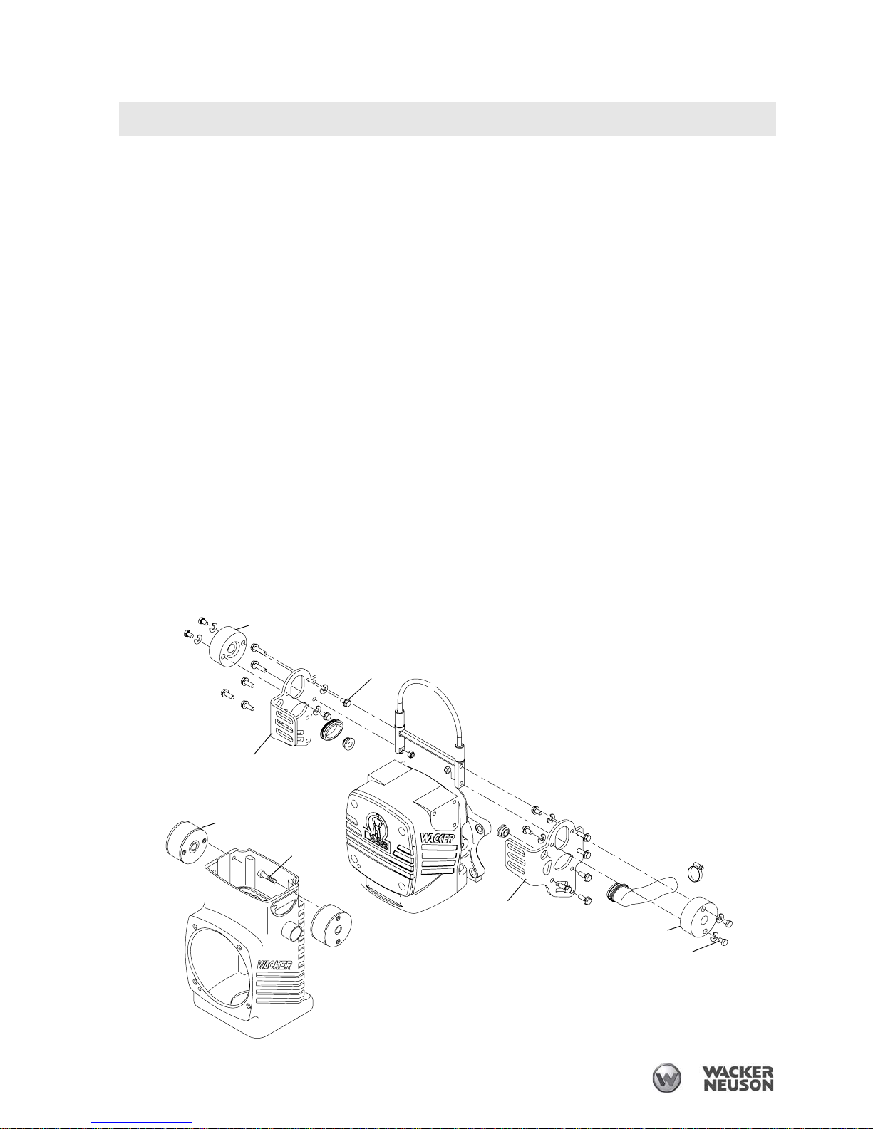
4.10.2 Inspect the shock mounts (a) and make sure that they are securely
mounted to the crankcase. Replace the shock mounts if they are torn
or damaged.
4.10.3 Remove the four socket head cap screws (b) that hold the shock
mounts to the crankcase. On Rammers with guards, remove the
guards (c) from the crankcase. Then, remove the screws that hold the
shock mounts to the guard. When reinstalling the shock mounts, apply
Loctite 243 or an equivalent to the screws and torque them to 34 Nm
(25 ft.lbs.).
Note: Replace the shock mounts as a set. Check the shock mount
screws after the first five hours of operation and tighten them if
necessary.
a
wc_gr003705
a
a
b
b
c
c
b
Page 46

Engine and Upper Machine Components Rammer Repair
46 wc_tx001546gb.fm
4.11 Tillotson Carburetor (BS 500/600/700/650 only)
See Graphic: wc_gr001308rm
Recommended Tools
Ratchet Wrench
Torque Wrench
Hex Key or Hex Socket: 4 mm, 6 mm
Screwdriver
Loctite 243 (blue)
The Tillotson carburetor uses a fixed low and high speed fuel jet. The
only adjustment is to set the engine idle speed.
Refer to section Technical Data for the correct idle and operating rpm.
For best accuracy, use a tachometer when making carburetor
adjustments.
NOTICE: The engine is lubricated by the fuel mixture; running the
engine too lean could cause it to overheat.
High Altitude Operation
The WM 80 engine used in the rammers is designed to operate most
efficiently at normal altitudes (1524 meters) (up to 5000 ft.). At high
altitudes (1524 meters) (above 5000 ft.) minor modifications to the
carburetor can be made to improve its performance. All modifications
must be performed by an authorized WACKER dealer. Contact
WACKER Corporation for more information.
High altitude operations involve modifications to the engine air/fuel
mixture. At normal altitudes, these modifications can be damaging to
the engine components. When returning the rammer to normal altitude
operation, remember to reset the carburetor to its standard
specifications.
Setting Idle Speed Adjustment
4.11.1 Start the engine and allow it to warm up to operating temperature.
4.11.2 Set the engine idle speed with the engine running at idle and the choke
(a) fully open. Adjust the idle speed screw (b) in or out to obtain the
correct idle speed.
NOTICE: DO NOT turn the adjusting screw in too tightly or you may
damage the carburetor.
Removing the Carburetor
4.11.3 Remove the three socket head cap screws holding the carburetor
guard to the engine. When reinstalling the carburetor guard, apply
Loctite 243 and torque the screws to 23 Nm (17 ft. lbs.).
Page 47
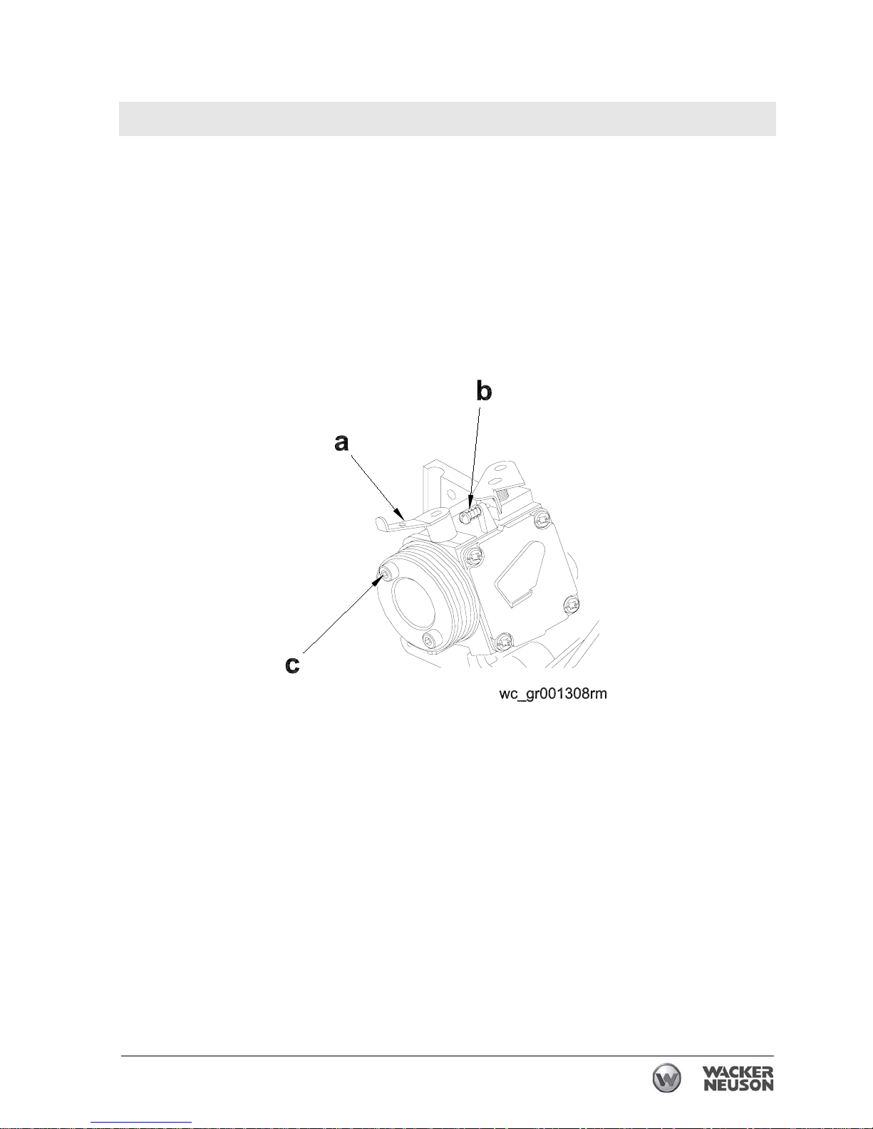
Rammer Repair Engine and Upper Machine Components
wc_tx001546gb.fm 47
4.11.4 Close the fuel valve and disconnect the fuel line from the carburetor.
See the section Fuel Lines for removal of fuel and vent lines for models
BS 50/60/70/65.
4.11.5 Loosen the air duct clamps and remove the air duct.
4.11.6 Remove the two socket head cap screws (c) holding the carburetor to
the engine. When reinstalling the carburetor, apply Loctite 243 and
torque the screws to 5.4 Nm (4.0 ft.lbs.).
Note: It is not necessary to disconnect the throttle cable to remove the
carburetor.
Page 48
Engine and Upper Machine Components Rammer Repair
48 wc_tx001546gb.fm
4.12 Fuel Lines (BS 50/60/70-2, BS 65)
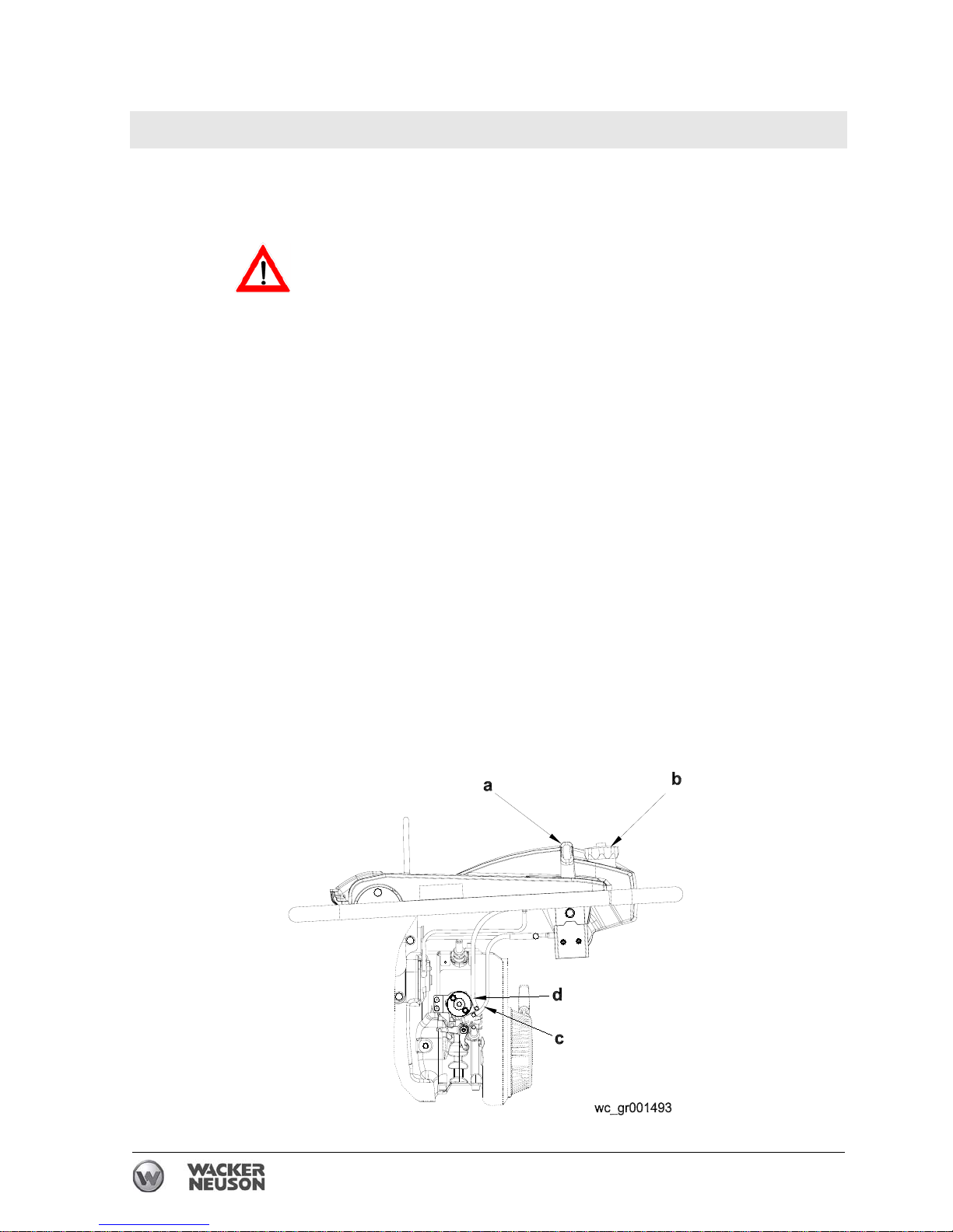
See Graphic: wc_gr001493
ALWAYS follow the instructions when disconnecting the fuel lines.
Failure to do so may result in fuel leaking from the fuel system.
To disconnect the fuel lines:
4.12.1 Shut off the engine by moving the throttle through the detent to the off
position (a). The engine will stop and the fuel valve will close.
4.12.2 Open the fuel cap (b) to relieve normal operating pressure, and then
retighten it.
4.12.3 Remove the protective guard.
4.12.4 Pinch off both the fuel feed line (c) and the vent line (d) as close to the
carburetor as possible.
4.12.5 Carefully remove the fuel lines and drain the fuel left in the fuel lines
into an approved container.
Note: In the interests of environmental protection, place a plastic sheet
and a container under the machine to collect any liquid which drains
off. Dispose of this liquid in accordance with environmental protection
legislation.
4.12.6 After service is complete, reconnect the lines to the proper fittings.
Reconnect the fuel feed line (c) from the valve to the lower fitting and
the vent line (d) from the top of the tank to the upper fitting.
4.12.7 Replace the protective guard.
CAUTION
Page 49
Rammer Repair Engine and Upper Machine Components
wc_tx001546gb.fm 49
4.13 Fuel Tank (BS Models)
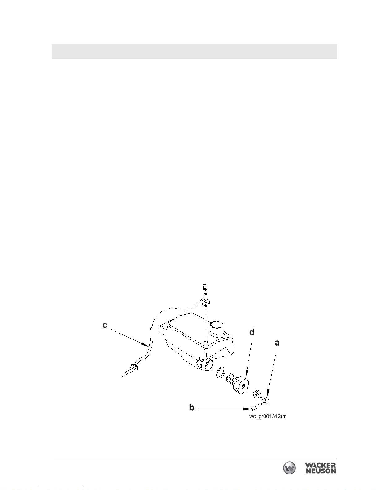
See Graphic: wc_gr001312rm
4.13.1 Remove the silencing cover.
4.13.2 Close the fuel valve (a).
4.13.3 Disconnect the fuel line (b) from the fuel tank. Disconnect the vent line
(c) where used.
4.13.4 Drain the fuel into a suitable container.
Note: In the interests of environmental protection, place a plastic sheet
and a container under the machine to collect any liquid which drains
off. Dispose of this liquid in accordance with environmental protection
legislation.
4.13.5 Remove the four socket head cap screws that hold the fuel tank to the
guide handle. When reinstalling the fuel tank, apply Loctite 243 and
torque the screws to 9.4 Nm (6.9 ft. lbs.).
4.13.6 Unscrew the filter (d) from the fuel tank.
Note: It is not necessary to separate the fuel valve from the fuel filter
unless replacing the parts. To separate, pull and twist the fuel valve
from the fuel filter.
4.13.7 Clean the fuel filter. Replace the fuel filter if the mesh element is torn
or punctured.
4.13.8 Clean the inside of the fuel tank to remove any sediment.
Page 50

Engine and Upper Machine Components Rammer Repair
50 wc_tx001546gb.fm
4.14 Fuel Tank (DS Models)
See Graphic: wc_gr001313rm
4.14.1 Remove the silencing cover.
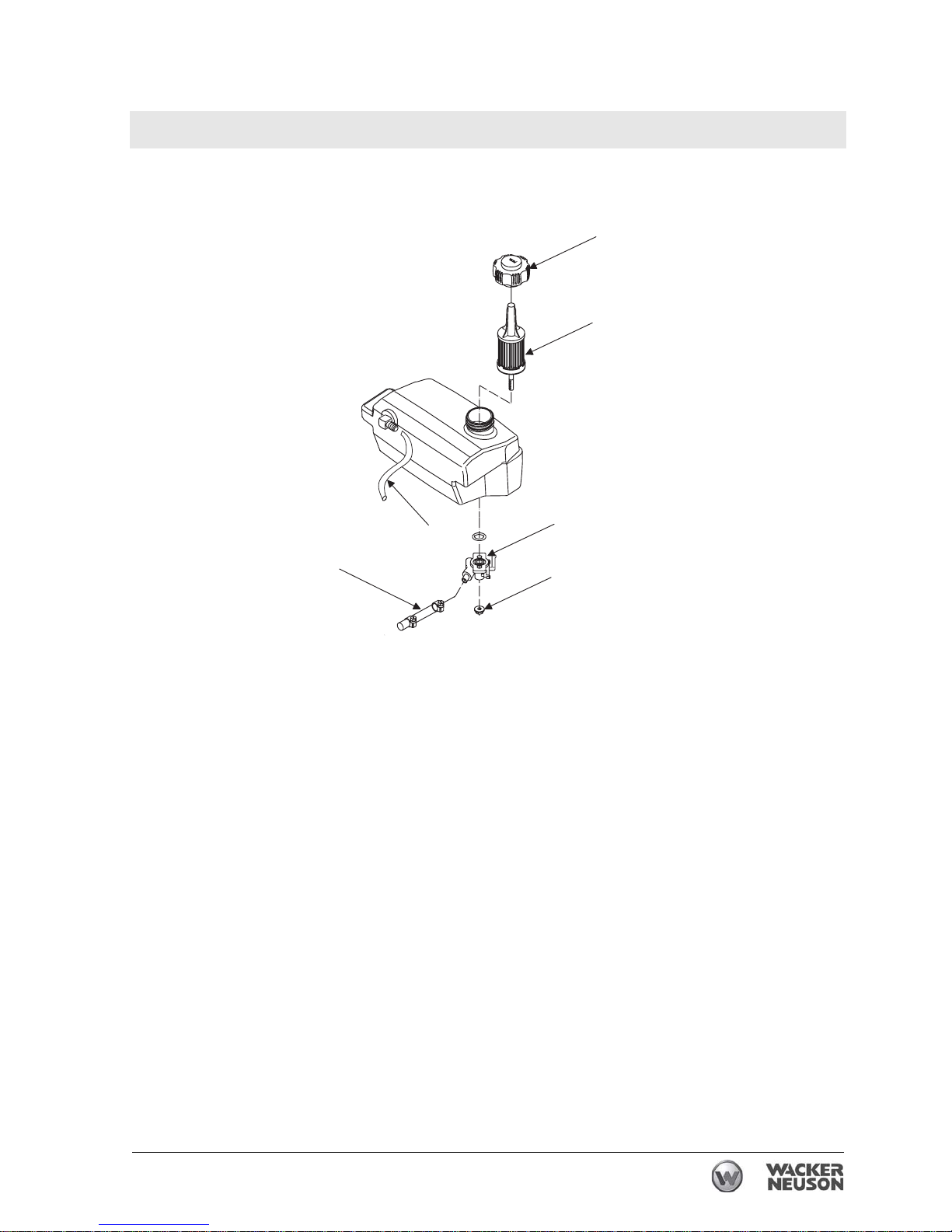
4.14.2 Disconnect the fuel supply line (f) and fuel return line (c) from the fuel
tank and drain the fuel into a suitable container.
Note: In the interests of environmental protection, place a plastic sheet
and a container under the machine to collect any liquid which drains
off. Dispose of this liquid in accordance with environmental protection
legislation.
4.14.3 Remove the M6 screw that holds the fuel tank to the guide handle.
When reinstalling the fuel tank, apply Loctite 243 and torque the screw
to 9.4 Nm (6.9 ft.lbs.).
4.14.4 To remove the fuel filter (b), unscrew the two nuts (e) holding the fuel
supply valve (d) to the fuel tank. The fuel supply valve will come off.
4.14.5 Unscrew the cap (a) from the tank.
4.14.6 Carefully remove the fuel filter with needle-nose pliers.
4.14.7 Replace the fuel filter if the paper element is torn, punctured, or
clogged.
4.14.8 Clean the inside of the fuel tank to remove any sediment.
Page 51
Rammer Repair Engine and Upper Machine Components
wc_tx001546gb.fm 51
wc_gr001313rm
a
b
d
e
c
f
Page 52

Engine and Upper Machine Components Rammer Repair
52 wc_tx001546gb.fm
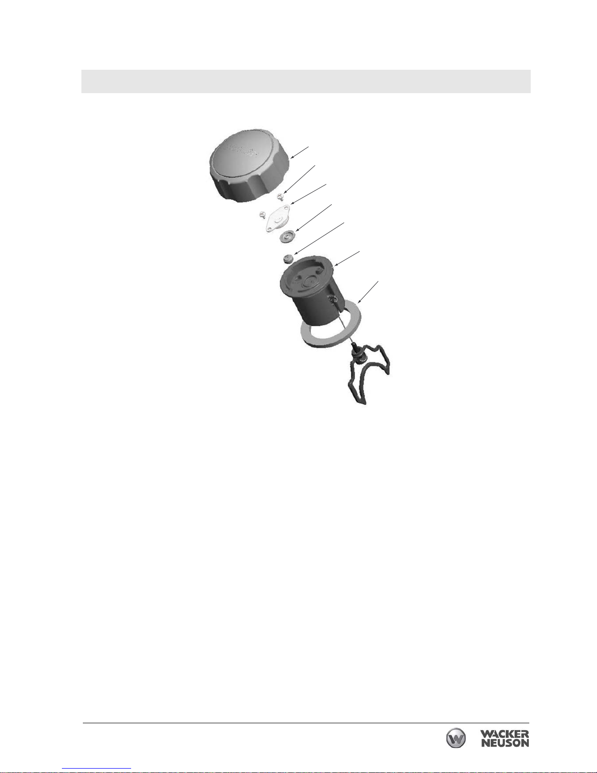
4.15 Fuel Tank Cap
See Graphic: wc_gr004562
To disassemble and clean the fuel tank cap:
4.15.1 Grasp the fuel tank cap (a) in one hand and the baffle (b) in the other.
4.15.2 Pull and twist the baffle left and right to separate it from the fuel tank
cap.
4.15.3 Remove the fuel tank gasket (c) from the baffle.
4.15.4 Remove the green umbrella valve (d).
4.15.5 Remove the two screws (e), the diaphragm retainer (f), and then the
diaphragm itself (g).
4.15.6 Clean all parts with soapy water and rinse thoroughly. DO NOT use
chemical solvents.
To reassemble the fuel tank cap:
4.15.1 Insert the green umbrella valve (d) into the top side of the baffle (b).
Press on the valve to seat it properly in the baffle.
4.15.2 Re-install the diaphragm (g) and attach the diaphragm retainer (f) with
the two screws (e). Torque the screws to 0.28 Nm (2.5 in.lbs.), being
careful not to strip them.
4.15.3 Re-install the fuel tank gasket (c) on the baffle.
4.15.4 Place the baffle assembly in the fuel tank cap (a). Use a screwdriver or
similar blunt instrument to work the fuel tank gasket into the threads of
the fuel tank cap until the baffle assembly snaps into place.
Page 53
Rammer Repair Engine and Upper Machine Components
wc_tx001546gb.fm 53
e
b
c
d
wc_gr004562
a
g
f
Page 54

Engine and Upper Machine Components Rammer Repair
54 wc_tx001546gb.fm
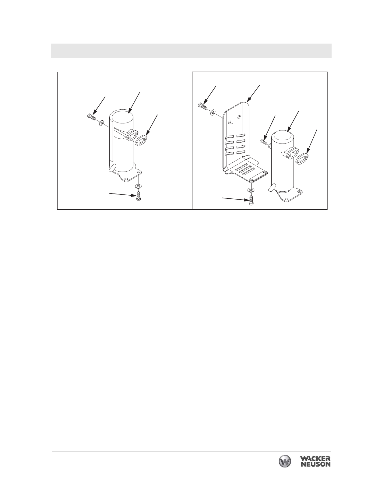
4.16 Muffler (pre-2009 BS Models)
See Graphic: wc_gr001314rm
Recommended Tools
Ratchet wrench
Torque wrench
Hex key: 5 mm
Hex key or hex socket: 6 mm
Socket: 19 mm (3/4”)
Loctite 243 (blue)
Carbon deposits can form in the muffler (d) and in the cylinder exhaust
port. If allowed to accumulate, they will gradually restrict the exhaust
passages, resulting in poor engine performance and hard starting.
Factors contributing to this problem include:
• Too much oil in the fuel mixture
• Dirty air filter causing the engine to run rich
• Excessive engine idling
• Dirty carburetor
4.16.1 Remove the two hex head cap screws (a) holding the muffler guard (b)
to the muffler (d). When reinstalling the muffler guard, apply Loctite
243 and torque the screws to 35 Nm (25 ft.lbs.).
4.16.2 Remove the two socket head cap screws (f) holding the muffler and
the muffler guard to the engine cylinder. When reinstalling the muffler
and the muffler guard, apply Loctite 243 and torque the screws to 23
Nm (17 ft.lbs.).
4.16.3 Remove the two socket head cap screws (c) located inside the muffler.
4.16.4 Remove the muffler.
4.16.5 Slowly pull the starter rope until the piston is at the top of its stroke and
is covering the exhaust port. This prevents dirt from entering the
engine cylinder.
4.16.6 Remove any carbon deposits on the engine exhaust port with a blunt
scraper.
4.16.7 Replace the silencer gasket (e).
4.16.8 Soak the muffler in carburetor cleaner or a similar cleaning solution for
several hours.
4.16.9 Drain the muffler and blow it dry.
Page 55
Rammer Repair Engine and Upper Machine Components
wc_tx001546gb.fm 55
4.17 Engine Cooling Fins
Recommended Tools
Screwdriver
Compressed air
The Wacker WM 80 engine is air cooled, so dirt accumulation between
the cylinder ribs may cause the engine to overheat. Use a screwdriver
to remove any dirt that is impacted between the cylinder ribs. Clean the
entire area using compressed air.
wc_gr001314rm
a
b
c
d
e
f
a
d
e
f
18 Nm
(13 ft.lbs.)
18 Nm
(13 ft.lbs.)
35 Nm
(25 ft.lbs.)
23 Nm
(17 ft.lbs.)
23 Nm
(17 ft.lbs.)
Page 56

Engine and Upper Machine Components Rammer Repair
56 wc_tx001546gb.fm
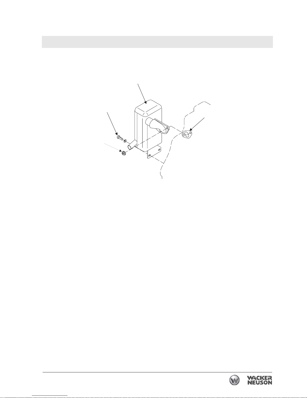
4.18 Muffler (DS Models)
See Graphic: wc_gr001315rm
Recommended Tools
Ratchet wrench
Torque wrench
Hex key: 5 mm
Hex key or hex socket: 6 mm
Socket: 19 mm (3/4”)
Loctite 243 (blue)
Carbon deposits can form in the muffler (a) and in the cylinder exhaust
port. If allowed to accumulate, they will gradually restrict the exhaust
passages resulting in poor engine performance and hard starting.
Factors contributing to this problem include:
• Dirty air filter causing the engine to run rich
• Excessive engine idling
4.18.1 Remove the two nuts (b) and two screws (c) holding the muffler to the
engine cylinder. When reinstalling the muffler, apply Loctite 243 and
torque the screws to 23 Nm (17 ft.lbs.).
4.18.2 Remove the muffler.
4.18.3 Remove any carbon deposits on the engine exhaust port with a blunt
scraper.
4.18.4 Replace the muffler gasket (d) P/N 0073660.
4.18.5 Soak the muffler in carburetor cleaner or a similar cleaning solution for
several hours.
4.18.6 Drain the muffler and blow it dry.
Page 57
Rammer Repair Engine and Upper Machine Components
wc_tx001546gb.fm 57
w c _ g r 0 0 1 3 1 5 r m
=
?
>
@
Page 58
Engine and Upper Machine Components Rammer Repair
58 wc_tx001546gb.fm
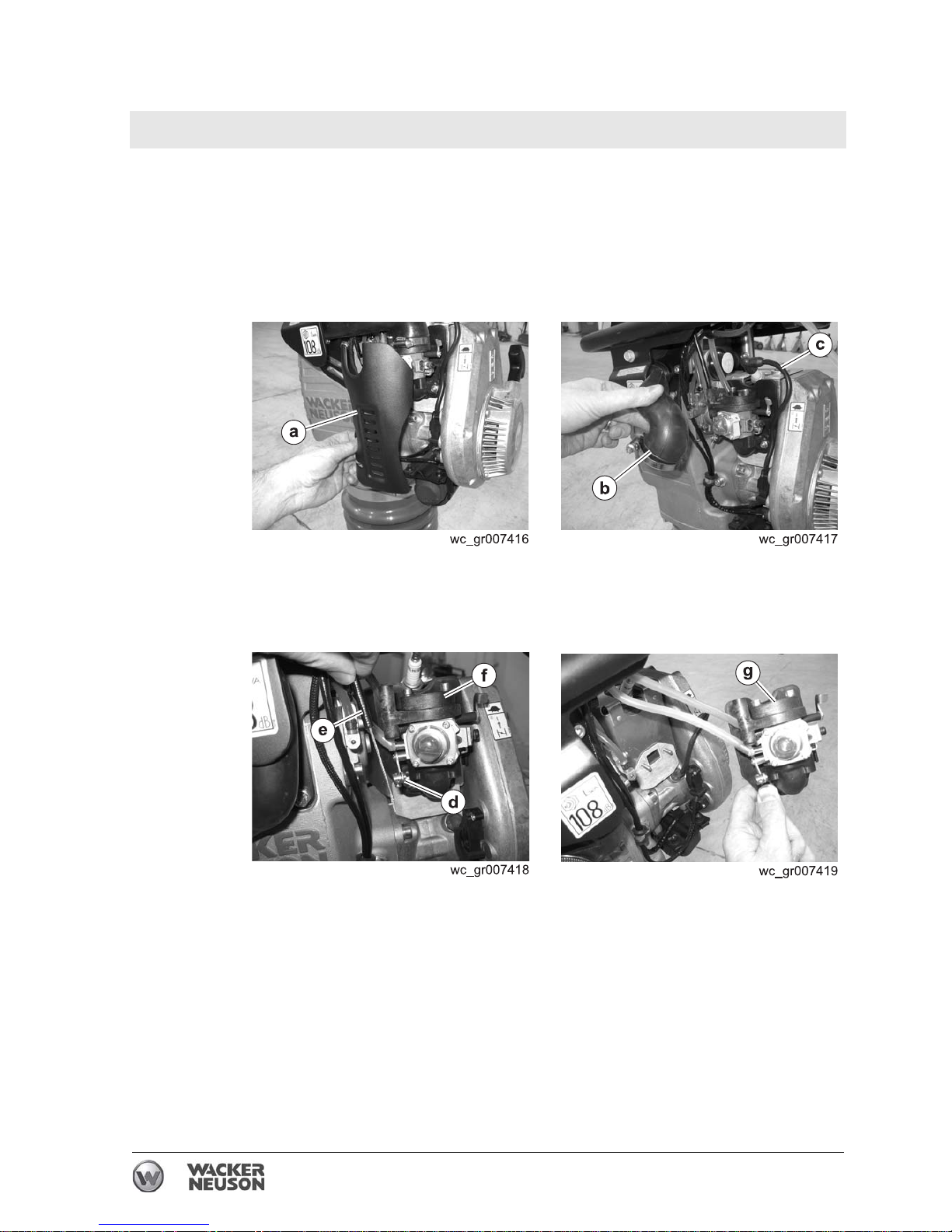
4.19 Replacing the Carburetor (WM 80 engines)
Removal
Removing Walbro Carburetor (auto-release choke models)
4.19.1 Stop the machine and allow it to cool.
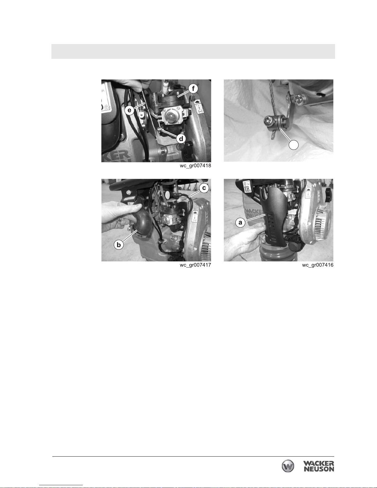
4.19.2 Remove the carburetor guard (a).
4.19.3 Loosen the hose clamp and remove the air duct (b).
4.19.4 Disconnect the ignition wire (c) from the spark plug.
4.19.5 Loosen the clamp (d) and remove the throttle cable (e) from the
carburetor adapter (f).
4.19.6 Remove the two nuts and washers and remove the carburetor
assembly
(g) from the machine.
This procedure continues on the next page.
Page 59
Rammer Repair Engine and Upper Machine Components
wc_tx001546gb.fm 59
Continued from the previous page.
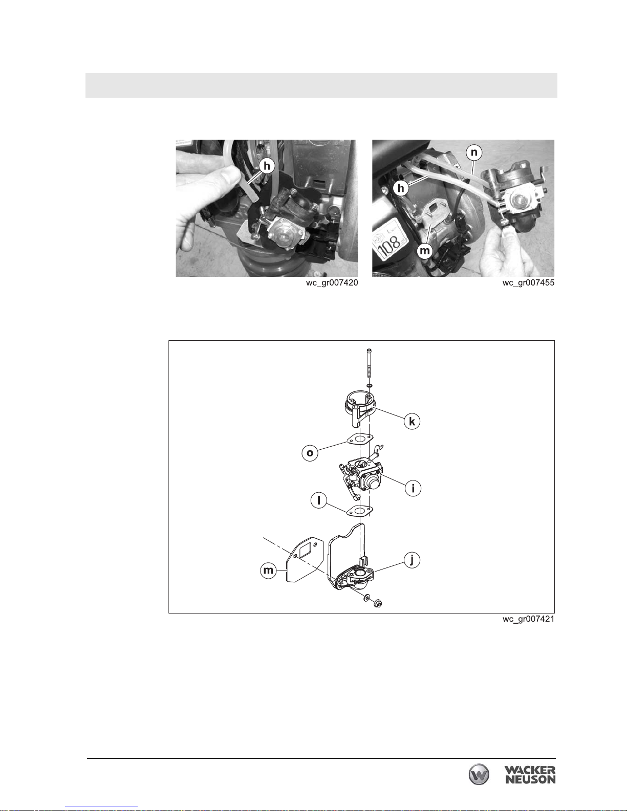
4.19.7 Have a container ready, then remove the oil hose (h) and drain it.
4.19.8 Make sure the throttle is in the OFF position. This position also closes
the fuel valve. Then, remove the fuel hose (n) and drain it.
4.19.9 Remove the gasket (m).
4.19.10 Disassemble the carburetor (i) from the adapter (j), flange (k), and
gaskets (l and o).
Result
The removal procedure is now complete.
Page 60
Engine and Upper Machine Components Rammer Repair
60 wc_tx001546gb.fm
Installation
Perform the procedure below to install the carburetor
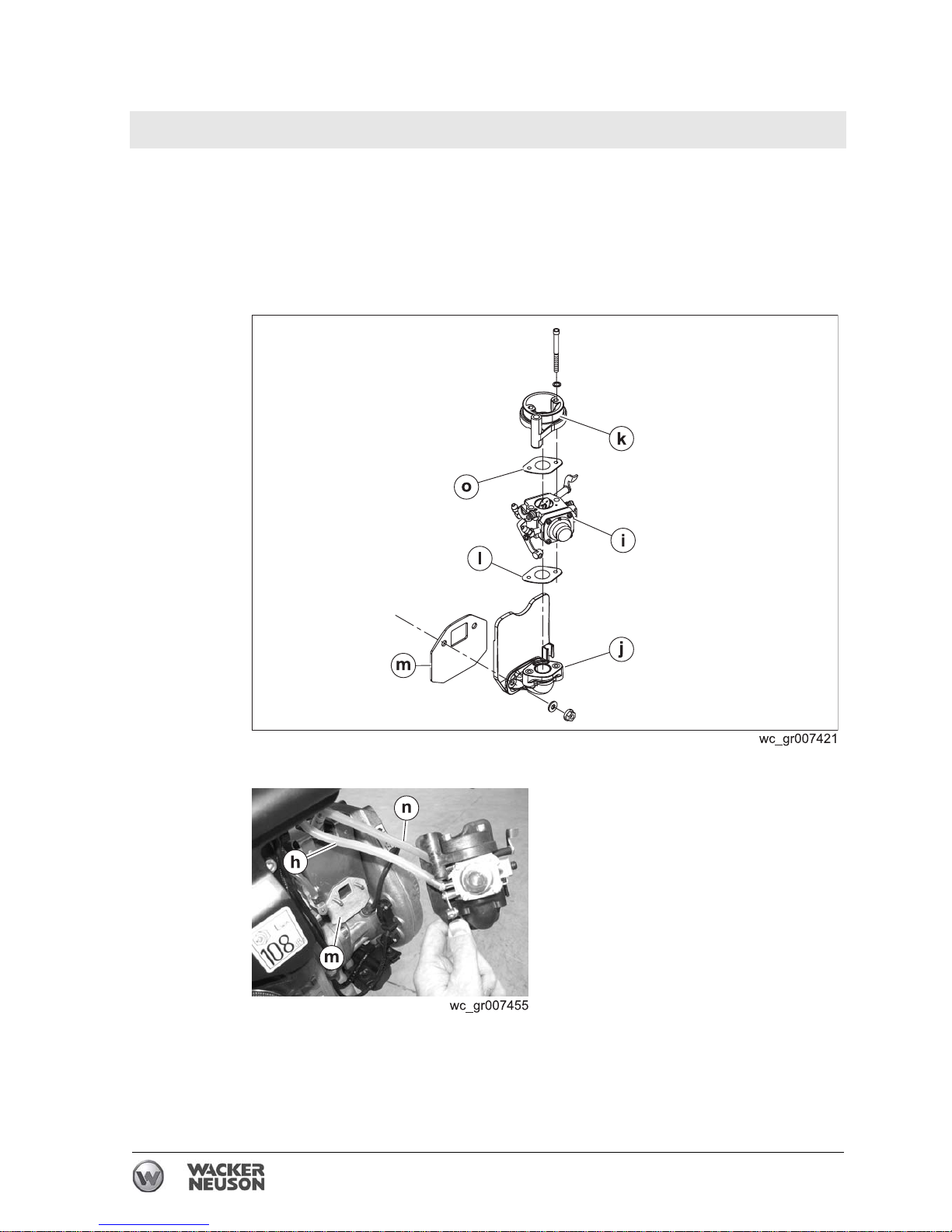
4.19.1 Assemble the adapter (j), lower gasket (l), flange (k), and upper
gasket
(o) to the carburetor (i). Note: The gaskets are not
interchangeable.
4.19.2 Connect the oil hose (h), and the fuel hose (n), to the carburetor.
4.19.3 Install the carburetor assembly to the engine.
Page 61
Rammer Repair Engine and Upper Machine Components
wc_tx001546gb.fm 61
4.19.4 Slide the throttle cable (e) through the adapter (f) and reconnect it to
the clamp
(d).
4.19.5 Install the air duct (b) with the hose clamp.
4.19.6 Using Loctite® 243 on the screws, install the carburetor guard (a).
Result
The installation procedure is now complete.
wc_gr007456
d
Page 62
Engine and Upper Machine Components Rammer Repair
62 wc_tx001546gb.fm
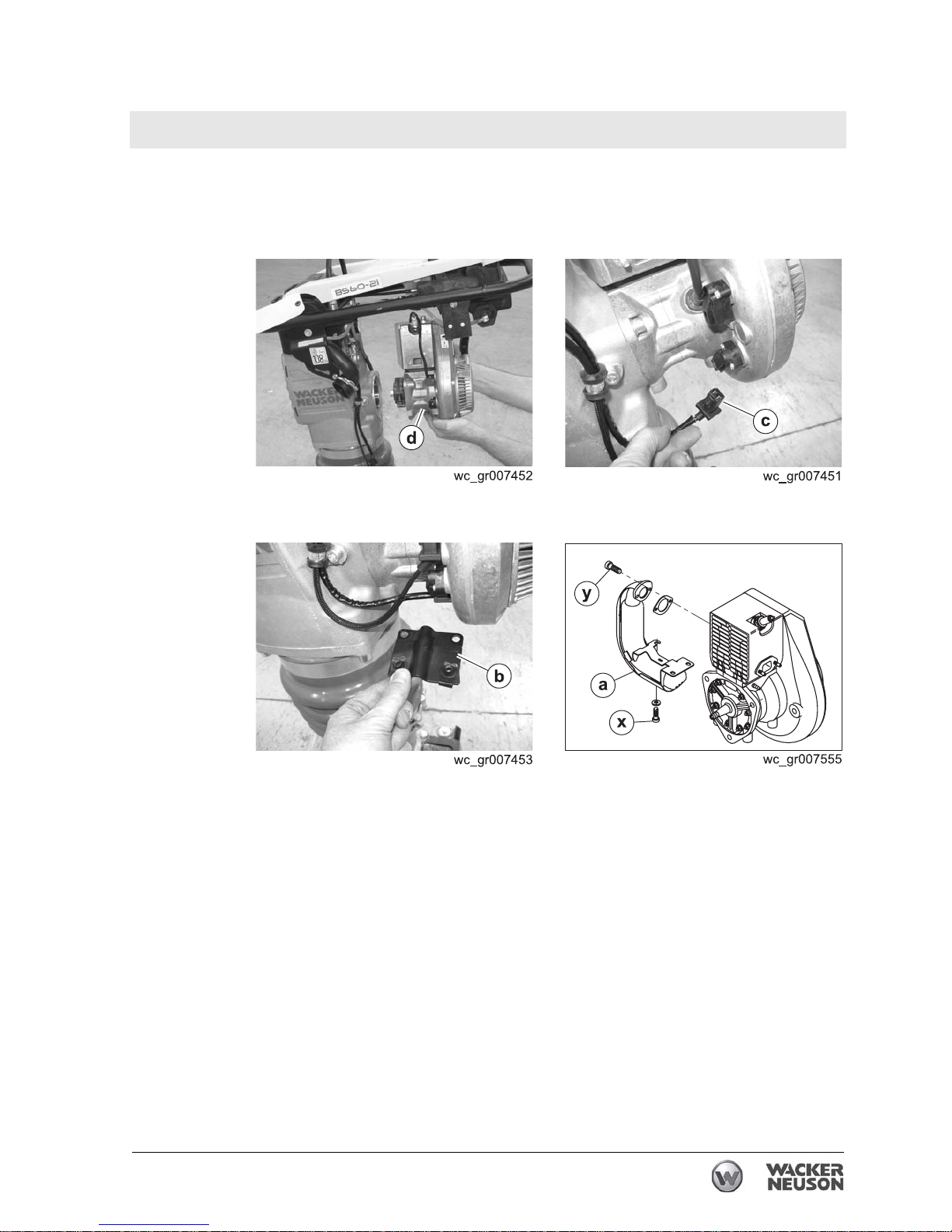
4.20 Replacing the WM 80 Engine (2010 and later models)
Requirements
• Engine cool
• Carburetor removed
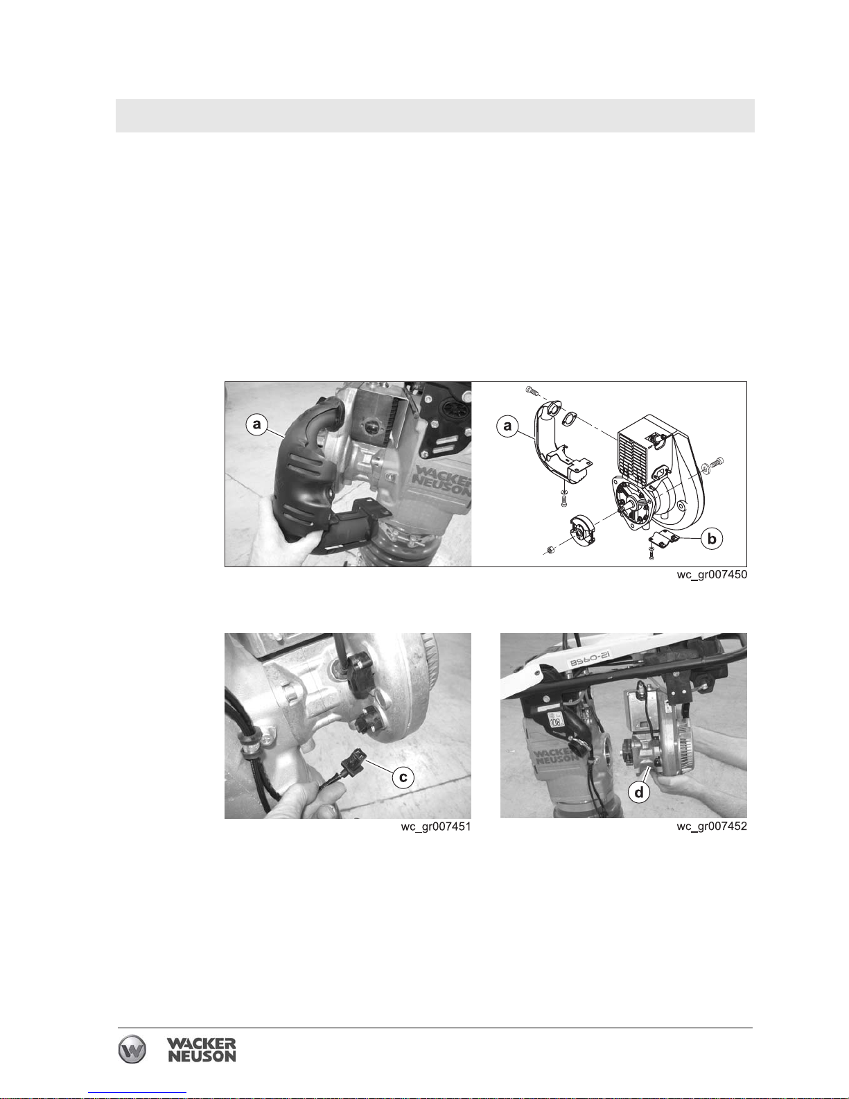
Removal
Perform the procedure below to remove the engine.
4.20.1 Remove the carburetor.
4.20.2 Remove the muffler (a).
4.20.3 Remove the bracket (b).
4.20.4 Disconnect the wiring to the switches (c).
4.20.5 Remove the screws that hold the engine and remove the engine
(d)
from the machine.
Result
The engine has now been removed.
Page 63
Rammer Repair Engine and Upper Machine Components
wc_tx001546gb.fm 63
Installation
Perform the procedure below to install the engine.
4.20.1 Install the engine (d) to the machine with three screws. Torque the
screws to 28 Nm (20 ft.lbs.).
4.20.2 Reconnect the wiring (c) to the switches.
4.20.3 Install the bracket (b).
4.20.4 Install the muffler (a). Torque screws (x) to 18 Nm (13 ft.lbs.). Torque
screw
(y) to 23 Nm (16 ft.lbs.).
4.20.5 Install the carburetor.
Result
The engine has now been installed.
Page 64

Engine and Upper Machine Components Rammer Repair
64 wc_tx001546gb.fm
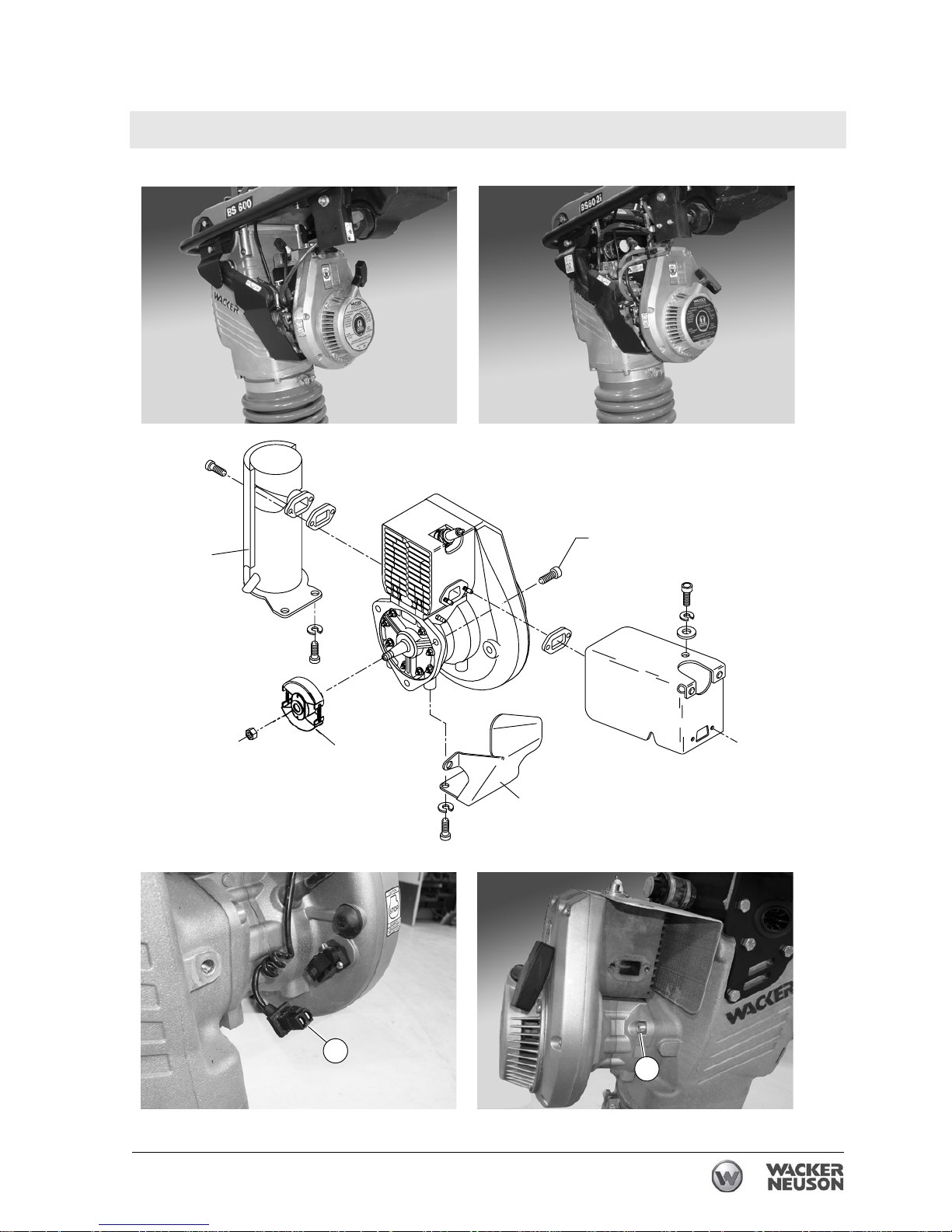
4.21 Replacing the WM 80 Engine (pre-2010 models)
See Graphic:wc_gr002935
Removal:
4.21.1 Stop the machine and allow it to cool.
4.21.2 Remove the carburetor. See section Removing Carburetor.
4.21.3 Remove the muffler guard (a) (if equipped) and the muffler (b).
4.21.4 Disconnect the connector (c) from the stop switch.
4.21.5 Remove the three socket head cap screws (d) that hold the engine to
the crankcase.
4.21.6 Tilt the engine down and away to remove it from the crankcase.
NOTICE: The rammer tips easily when the engine is removed.
DO NOT run the engine while it is off the machine unless the clutch (e)
has been removed. Running the engine with the clutch attached to the
crankshaft will cause the clutch shoes to separate and fly off.
Installation:
4.21.7 Position the engine onto the machine. Using Loctite 234 or equivalent
on the three screws (d), secure the engine to the machine. Torque the
screws to 27 Nm (20 ft.lbs.).
4.21.8 Reconnect the stop switch.
4.21.9 Install the muffler (b) and muffler guard (a).
4.21.10 Install the carburetor. See section Removing Carburetor.
WARNING
Page 65
Rammer Repair Engine and Upper Machine Components
wc_tx001546gb.fm 65
wc_gr002935
d
a
c
d
Page 66
Engine and Upper Machine Components Rammer Repair
66 wc_tx001546gb.fm
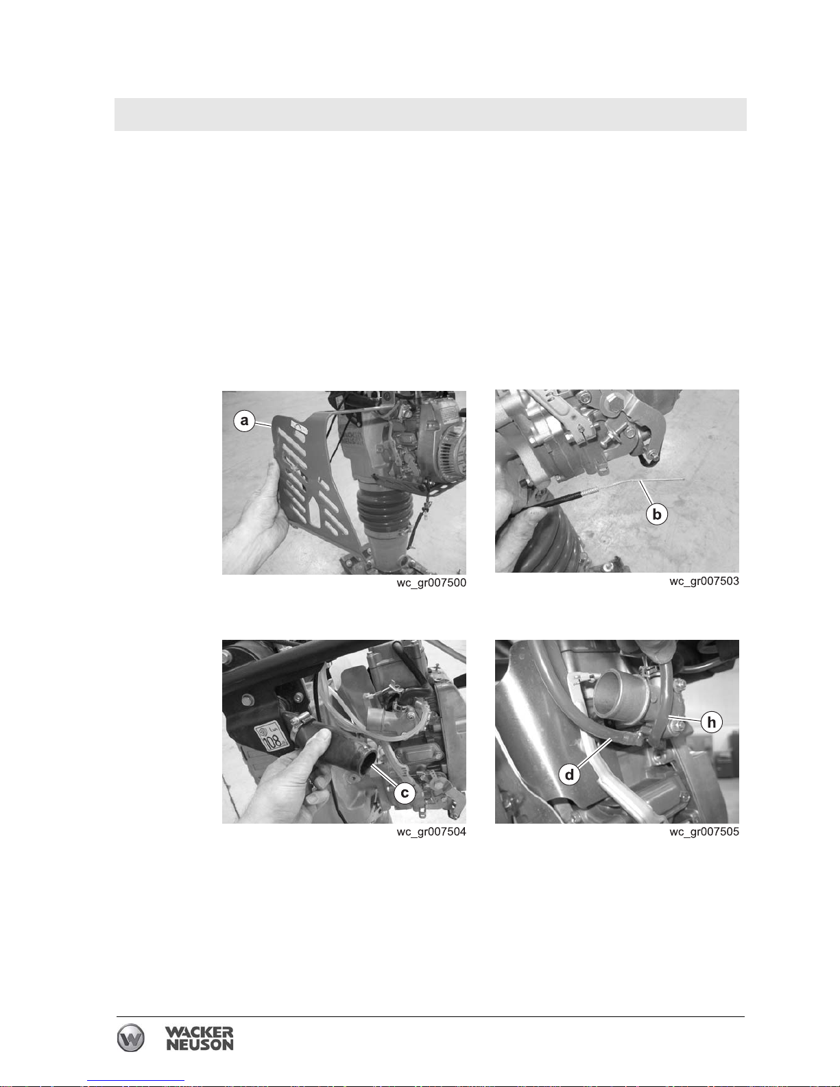
4.22 Replacing the Carburetor (WM 100 Engines)
Requirements
• Machine shut down and cool
• Loctite® 243 or equivalent
• Torque wrench
Removal
Perform the procedure below to remove the engine.
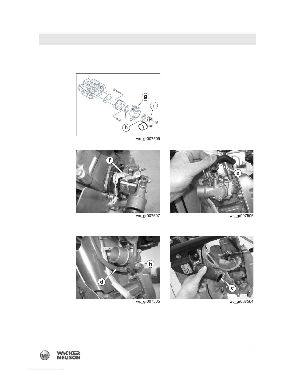
4.22.1 Disconnect the spark plug.
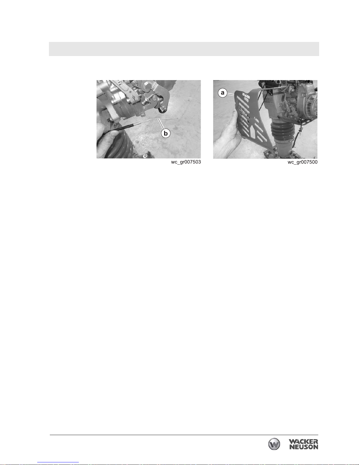
4.22.2 Remove the side guard (a).
4.22.3 Disconnect the throttle cable (b).
4.22.4 Disconnect the air hose (c).
4.22.5 Disconnect the fuel hose (d) and the compensation hose (h).
This procedure continues on the next page.
Page 67
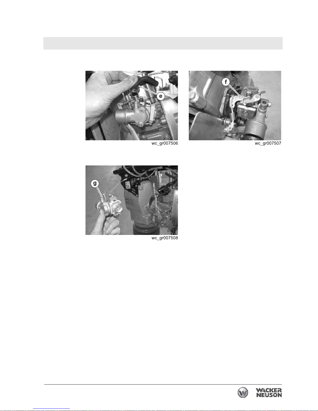
Rammer Repair Engine and Upper Machine Components
wc_tx001546gb.fm 67
Continued from the previous page.
4.22.6 Disconnect the hose (e).
4.22.7 Remove screw (f) and disconnect the linkage.
4.22.8 Remove the carburetor (g).
Result
The removal procedure is now complete.
Page 68
Engine and Upper Machine Components Rammer Repair
68 wc_tx001546gb.fm
Installation
Perform the procedure below to install the carburetor.
4.22.1 Install the carburetor (g), gaskets (h), and adapter (i).
4.22.2 Reconnect the linkage with screw (f).
4.22.3 Reconnect the hose (e).
4.22.4 Reconnect the fuel hose (d) and the compensation hose (h).
4.22.5 Reconnect the air hose
(c).
This procedure continues on the next page.
Page 69
Rammer Repair Engine and Upper Machine Components
wc_tx001546gb.fm 69
Continued from the previous page.
4.22.6 Reconnect the throttle cable (b).
4.22.7 Install the side guard (a).
Result
The replacement procedure is now complete.
Page 70
Engine and Upper Machine Components Rammer Repair
70 wc_tx001546gb.fm
4.23 Replacing the WM 100 Engine
Requirements
• Machine shut down and cool
• Loctite® 243 or equivalent
• Torque wrench
• Two wire ties
Removal
Perform the procedure below to remove the engine.
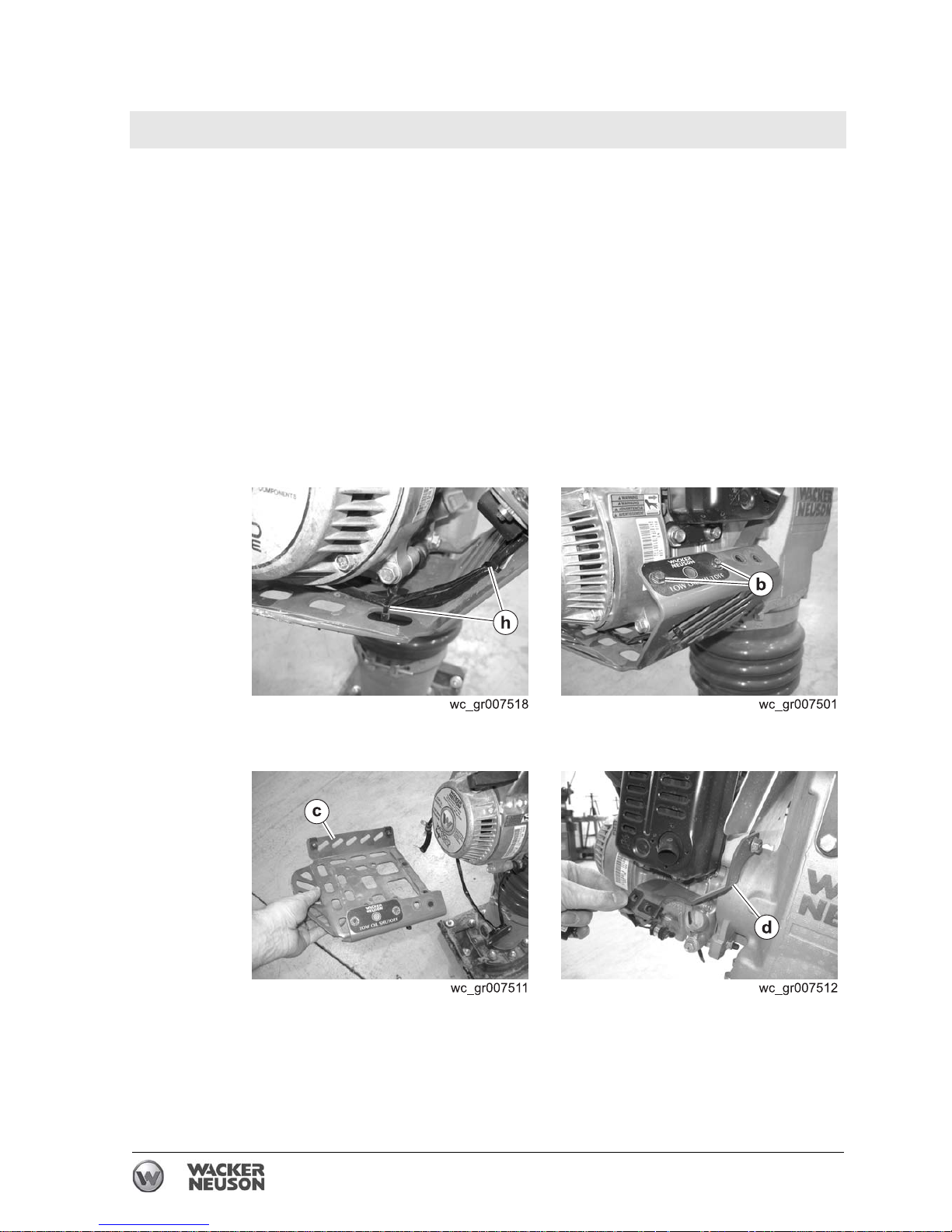
4.23.1 Remove the carburetor. See topic Replacing the Carburetor (WM 100
engine)
.
4.23.2 Clip the wire ties
(h).
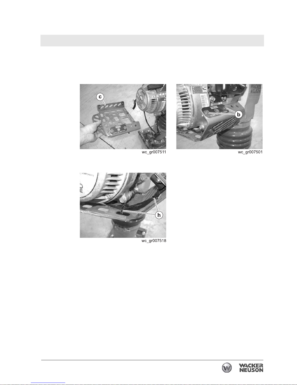
4.23.3 Remove the screws
(b) that hold the low oil shutdown switch.
4.23.4 Remove the lower guard (c).
4.23.5 Remove the support bracket
(d).
This procedure continues on the next page.
Page 71
Rammer Repair Engine and Upper Machine Components
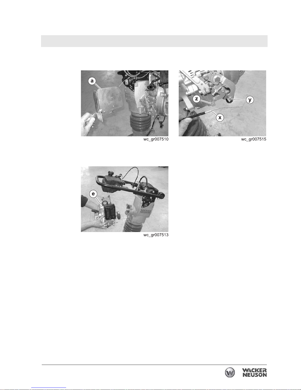
wc_tx001546gb.fm 71
Continued from the previous page.
4.23.6 Remove the heat shield (a).
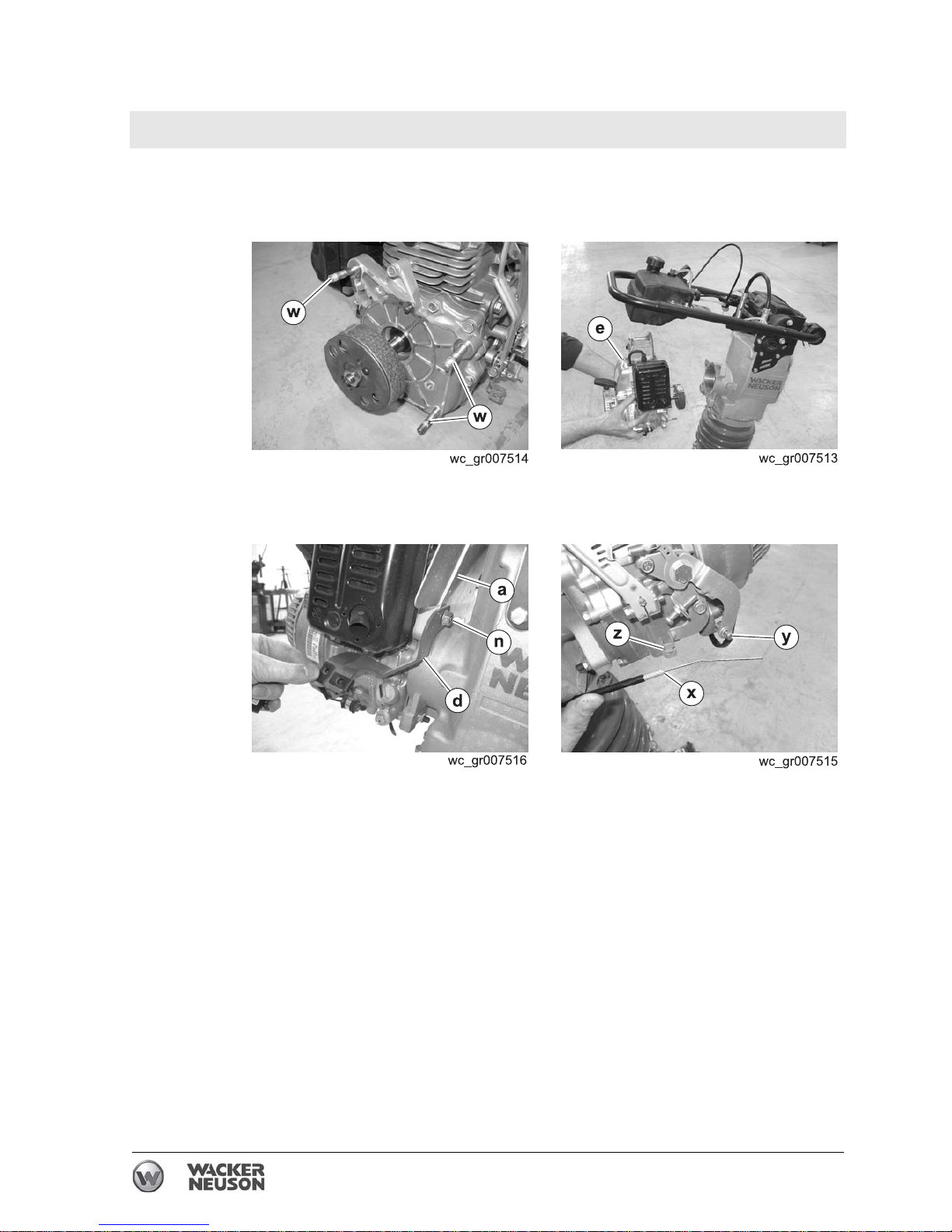
4.23.7 Disconnect the throttle cable (x) at the swivel (y) and the clamp (z).
4.23.8 Remove the nuts that hold the engine and remove the engine (e) from
the machine.
Result
The removal procedure is now complete.
Page 72
Engine and Upper Machine Components Rammer Repair
72 wc_tx001546gb.fm
Installation
Perform the procedure below to install the engine.
4.23.1 Apply Loctite® 243 to the four engine studs (w).
4.23.2 Slide the engine (e) (with clutch installed) into the machine.
4.23.3 Loosely install the support bracket (d) and heat shield (a) with nut (n).
Install the other three nuts and torque them to 25 Nm (18 ft.lbs.).
4.23.4 Reconnect the throttle cable (x) to the swivel (y) and the clamp (z).
This procedure continues on the next page.
Page 73
Rammer Repair Engine and Upper Machine Components
wc_tx001546gb.fm 73
Continued from the previous page.
4.23.5 Fit the lower guard to the support bracket. Then, using Loctite® 243
on the screws, install the lower guard (c) to the engine. Torque the
screws to 25 Nm (18 ft.lbs.). Torque the support bracket screw (n) to
25 Nm (18 ft.lbs.).
4.23.6 Install the low oil shutdown switch with screws (b).
4.23.7 Secure the wiring with new wire ties (h).
4.23.8 Reinstall the carburetor. See topic
Replacing the Carburetor .
Result
The replacement procedure is now complete.
Page 74

Engine and Upper Machine Components Rammer Repair
74 wc_tx001546gb.fm
4.24 Removing the WM 90 Engine
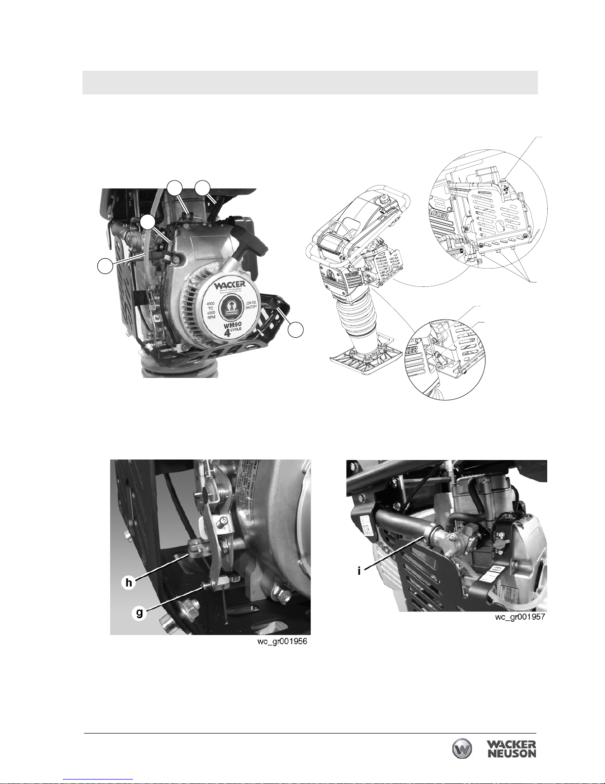
See Graphic: wc_gr001954, wc_gr003661, wc_gr001956, and wc_gr001957
4.24.1 Disconnect the spark plug cap (a) from the spark plug.
4.24.2 Disconnect the fuel line (b) from the carburetor and plug the line.
4.24.3 Disconnect the stop switch wire (c).
4.24.4 Disconnect the wiring (k) from the low-oil unit (l) (if equipped).
4.24.5 Remove the M8 x 16 bolt and washer (d) securing the guard to the
engine.
4.24.6 Remove the M8 bolt and washer (e) securing the guard to the rammer
crankcase.
4.24.7 Remove the six M8 bolts (f) securing the lower guard to the engine and
remove the guard.
4.24.8 Remove the wire running from the engine to the low-oil unit (if
equipped).
4.24.9 Loosen the retainer (g) from the throttle cable. Pry open the clamp (h)
and remove the throttle cable.
4.24.10 Loosen the clamp (i) securing the air intake hose to the carburetor and
remove the hose.
4.24.11 Remove the four nuts (j) securing the engine to the adapter and
remove the heat shield and the engine.
Page 75
Rammer Repair Engine and Upper Machine Components
wc_tx001546gb.fm 75
d
e
j
f
wc_gr001954
b
l
ac
k
wc_gr003661
Page 76
Engine and Upper Machine Components Rammer Repair
76 wc_tx001546gb.fm
4.25 Engine (DS Models)
See Graphic: wc_gr001317rm
Recommended Tools
Ratchet wrench
Torque wrench
Socket: 19 mm (3/4”)
Hex key: 5 mm
Hex key or hex socket: 4 mm, 6 mm
Screwdriver
4.25.1 Close the fuel valve.
4.25.2 Disconnect the fuel lines.
4.25.3 Loosen the throttle cable holder.
4.25.4 Disconnect the throttle cable.
4.25.5 Remove the four M10 nuts (a) that hold the engine to the crankcase.
When reinstalling the engine, torque the nuts to 49 Nm (36 ft.lbs.).
4.25.6 Tilt the engine down and away to remove it from the crankcase.
NOTICE: The rammer tips easily when the engine is removed.
DO NOT run the engine while it is detached from the machine unless
the clutch has been removed. Running the engine with the clutch
attached to the crankshaft will cause the clutch shoes to separate and
fly off.
WARNING
Page 77
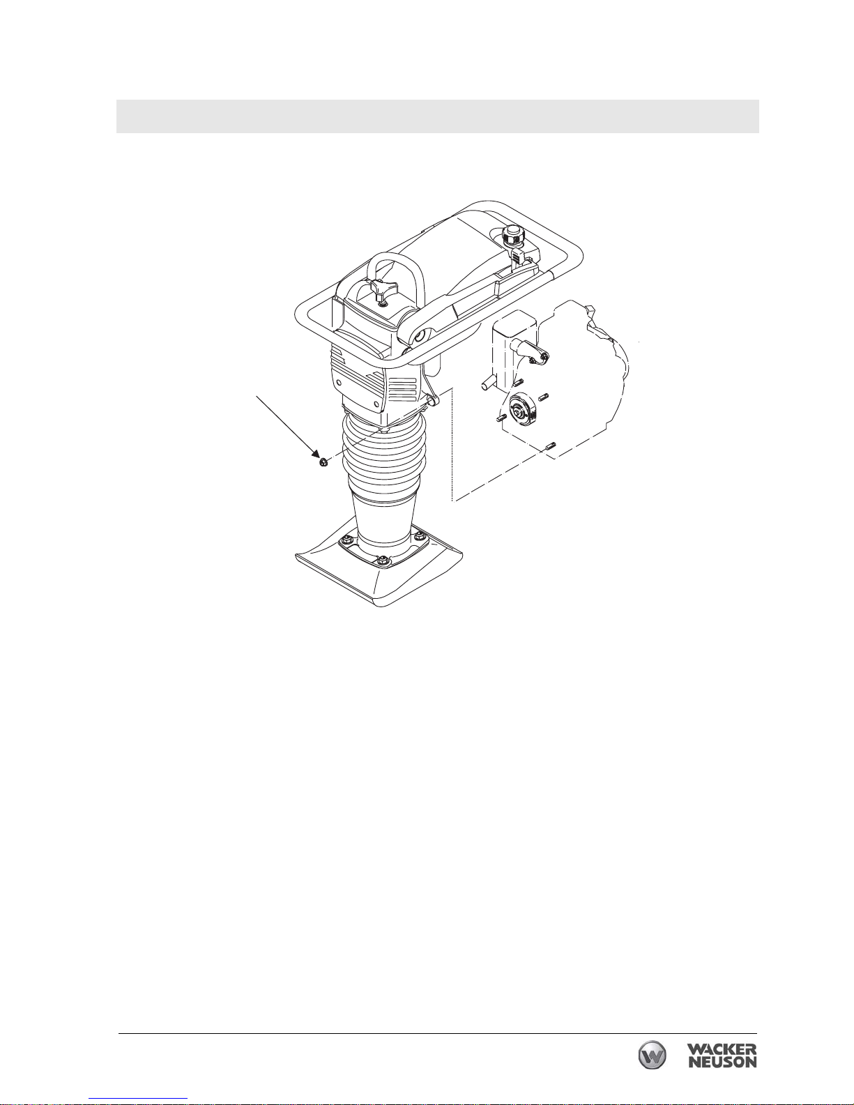
Rammer Repair Engine and Upper Machine Components
wc_tx001546gb.fm 77
w c _ g r 0 0 1 3 1 7 r m
=
Page 78

Engine and Upper Machine Components Rammer Repair
78 wc_tx001546gb.fm
4.26 Clutch (2- and 4-stroke models)
See Graphic: wc_gr007517
Recommended Tools
Impact wrench
Torque wrench
Socket: 17 mm
Needle-nose pliers
Clutch puller P/N 0117972
Removal
4.26.1 Remove the engine from the rammer.
4.26.2 Check the condition of the clutch shoes (a) and replace them if
necessary. The clutch shoes should be absolutely dry. If oil is present,
inspect the engine shaft seal.
4.26.3 Prevent the clutch from turning and use an air impact wrench and 17
mm socket to loosen the clutch nut (b). If an impact wrench is not
available, rap the wrench handle sharply to help break the nut loose.
Note: Loosen the nut but do not completely remove it from the engine
crankshaft. This will protect the crankshaft threads from the clutch
puller screw.
4.26.4 Screw the clutch puller (P/N 0117972) (c) (or other suitable puller) into
the small holes in the clutch and turn the center screw against the end
of the crankshaft until the clutch hub breaks free of the taper.
Note: When reinstalling the clutch, make sure the taper in the clutch
hub and on the engine crankshaft is absolutely free of any oil or
grease.
Installation
4.26.5 Place the clutch on the engine crankshaft.
4.26.6 Reinstall the clutch nut and torque to 35 Nm (25 ft.lbs.).
4.26.7 Reinstall the engine on the crankcase.
Page 79
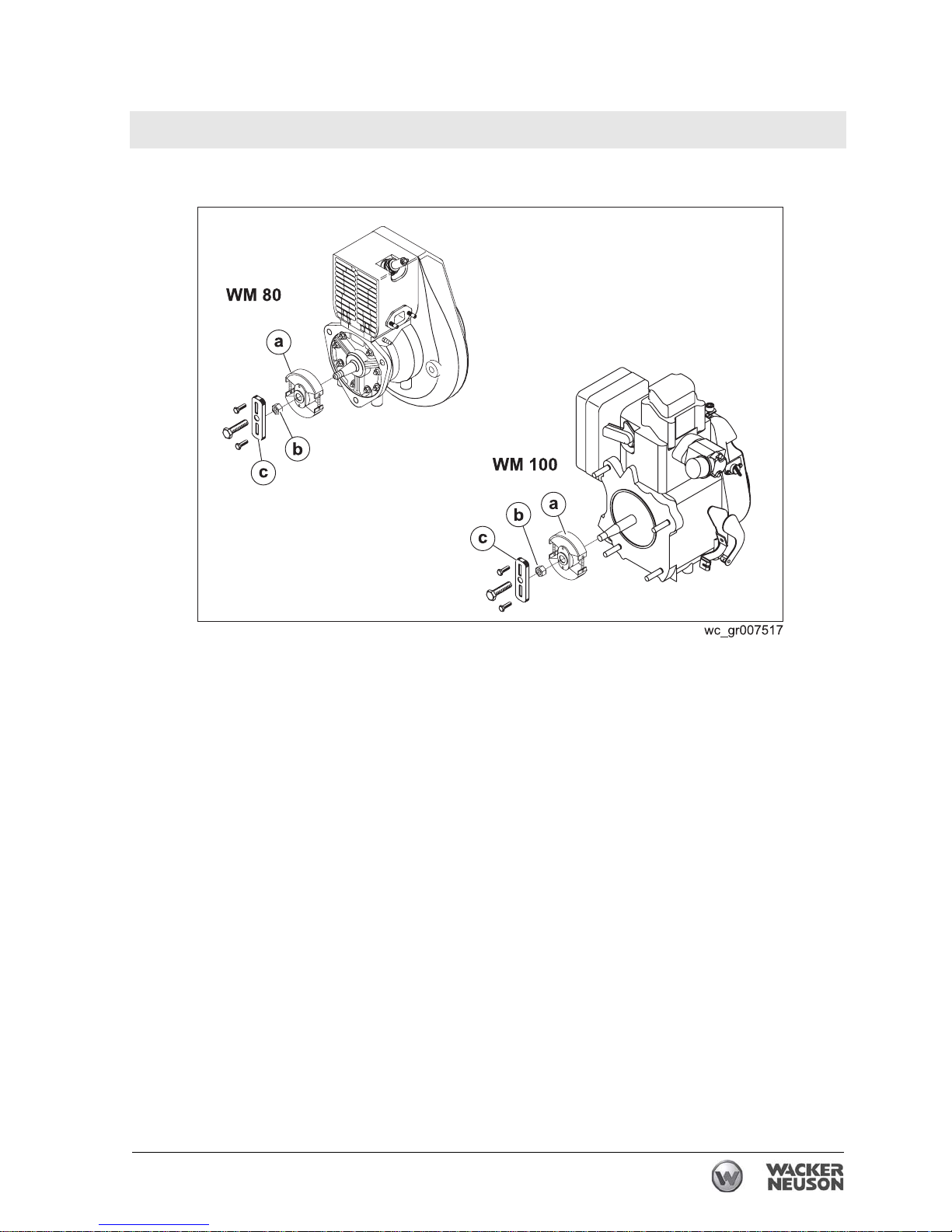
Rammer Repair Engine and Upper Machine Components
wc_tx001546gb.fm 79
BS Models
Page 80

Engine and Upper Machine Components Rammer Repair
80 wc_tx001546gb.fm
4.27 Clutch (DS 720 only)
See Graphic: wc_gr001319rm
Recommended Tools
Impact wrench
Torque wrench
Needle-nose pliers
Clutch puller P/N 0153566
Removal
4.27.1 Remove the engine from the rammer.
4.27.2 Check the condition of the clutch shoes (a) and replace them if
necessary. The clutch shoes should be absolutely dry. If oil is present,
inspect the engine shaft seal.
4.27.3 Prevent the clutch from turning and use an air impact wrench to loosen
the clutch bolt (b). If an impact wrench is not available, rap the wrench
handle sharply to help break the bolt loose.
Note: Loosen the bolt but do not completely remove it from the engine
crankshaft. This will protect the crankshaft threads from the clutch
puller screw.
4.27.4 Screw the clutch puller (P/N 0153566) (c) (or other suitable puller) into
the small holes in the clutch and turn the center screw against the end
of the crankshaft until the clutch hub breaks free of the taper.
Note: When reinstalling the clutch, make sure the taper in the clutch
hub and on the engine crankshaft is absolutely free of any oil or
grease.
Installation
4.27.5 Place the clutch on the engine crankshaft.
4.27.6 Reinstall the clutch bolt and torque to 27 Nm (20 ft.lbs.).
4.27.7 Reinstall the engine on the crankcase. Torque the screws to 49 Nm (36
ft.lbs.).
4.27.8 Perform an operation check. The clutch should be disengaged with the
throttle at the idle position.
Engine Speed (idle) (rpm): 1200 ± 200
Clutch Engagement (rpm): 2000 ± 200
Page 81
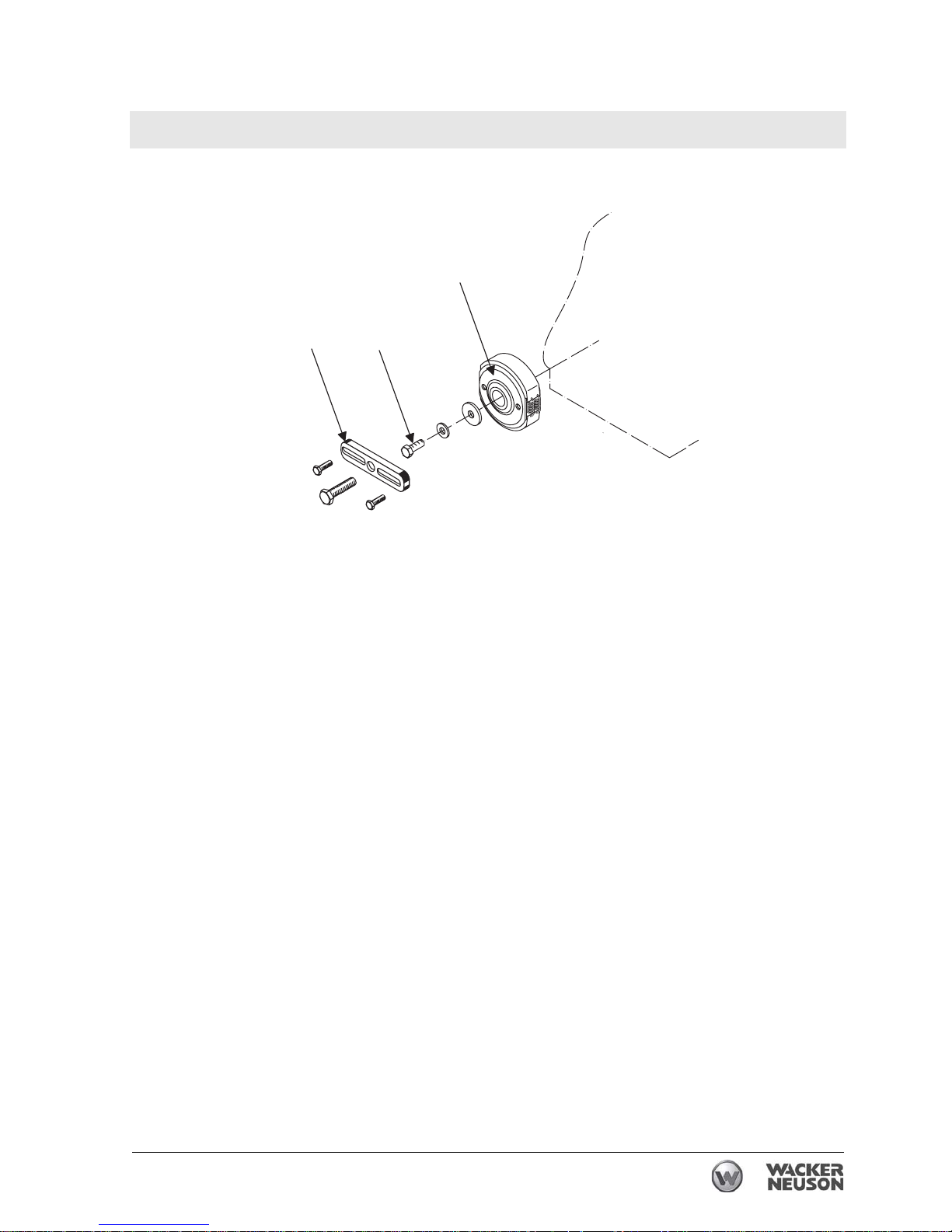
Rammer Repair Engine and Upper Machine Components
wc_tx001546gb.fm 81
c
a
b
wc_gr001319rm
DS 720 Models
Page 82

Engine and Upper Machine Components Rammer Repair
82 wc_tx001546gb.fm
4.28 Clutch (DS 70 only)
See Graphic: wc_gr002372rm
Recommended Tools
Impact wrench
Torque wrench
Needle-nose pliers
Clutch puller P/N 0153566
Removal
4.28.1 Remove the engine from the rammer.
4.28.2 Check the condition of the clutch shoes (a) and replace them if
necessary. The clutch shoes should be absolutely dry. If oil is present,
inspect the engine shaft seal.
4.28.3 Prevent the clutch from turning and use an air impact wrench to loosen
the clutch bolt (b). If an impact wrench is not available, rap the wrench
handle sharply to help break the bolt loose.
Note: Loosen the bolt but do not completely remove it from the engine
crankshaft. This will protect the crankshaft threads from the clutch
puller screw.
4.28.4 Screw the clutch puller (P/N 0153566) (c) (or other suitable puller) into
the small holes in the clutch and turn the center screw against the end
of the crankshaft until the clutch hub breaks free of the taper.
Installation
4.28.5 Place the clutch on the engine crankshaft.
4.28.6 Reinstall the clutch bolt and torque to 27 Nm (20 ft.lbs.).
4.28.7 Reinstall the engine on the crankcase. Torque the screws to 49 Nm (36
ft.lbs.).
4.28.8 Perform an operation check. The clutch should be disengaged with the
throttle at the idle position.
Engine Speed (idle) (rpm): 1050 ± 50
Clutch Engagement (rpm): 2500 ± 200
Page 83
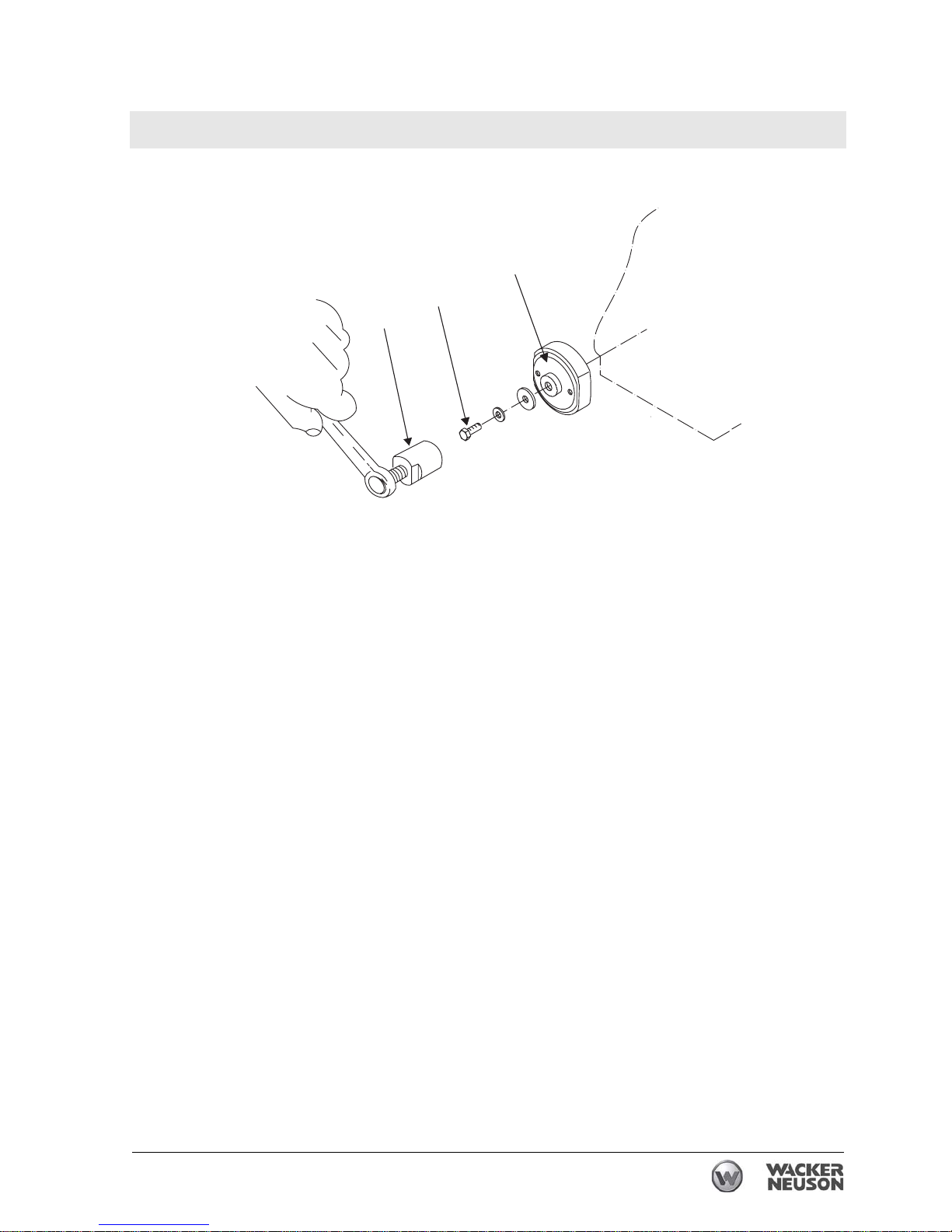
Rammer Repair Engine and Upper Machine Components
wc_tx001546gb.fm 83
DS 70 Models
wc_gr002372rm
a
b
c
Page 84

Ramming System Rammer Repair
84 wc_tx001547gb.fm
5 Ramming System
5.1 Bellows
Se Graphic: wc_gr001321rm
Recommended Tools
Ratchet wrench
Torque wrench
Hex key or hex socket: 8 mm
Socket: 13 mm
Punch
Rubber mallet
Screwdriver
Loctite 243
The bellows provides a flexible joint between the ramming system and
the upper machinery. It seals the ramming system and provides a path
for recirculating the oil. Periodically, tighten the clamps, clean the
bellows, and inspect the bellows for signs of damage or leaks.
Removal
5.1.1 Drain the oil into a suitable container as described in section Ramming
System Lubrication.
5.1.2 Remove the four socket head cap screws (c) that secure the ramming
system to the crankcase.
5.1.3 Stand on the ramming shoe and pull up hard on the crankcase until the
end plugs (h) are visible.
5.1.4 Drive out the end plugs and piston pin (g) holding the connecting rod
to the ram. Do not reuse the end plugs.
5.1.5 Lift the upper machinery from the ramming system.
5.1.6 Remove the O-ring (b); do not reuse.
5.1.7 To free the guide cylinder (a) from the bellows (e), loosen the top
bellows clamp (d), stand on the ramming shoe, and pull up hard on the
guide cylinder.
5.1.8 To free the bellows from the protective pipe (j), loosen the bottom
bellows clamp (f), stand on the ramming shoe, pull on the bellows, and
rap along the bottom of the bellows with a rubber mallet.
Page 85
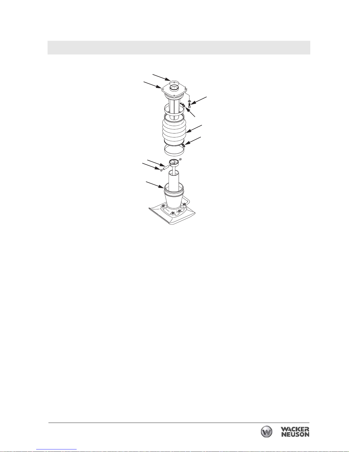
Rammer Repair Ramming System
wc_tx001547gb.fm 85
Installation
5.1.9 Oil the inner edges of the bellows.
5.1.10 Place the lower clamp (f) on the protective pipe (j).
5.1.11 Press the bellows (e) onto the protective pipe (j) with a strong
downward push.
5.1.12 Partially tighten the clamp onto the bellows.
5.1.13 Place the upper clamp (d) on the bellows.
5.1.14 Press the guide cylinder (a) onto the bellows with a strong downward
push.
5.1.15 Partially tighten the spring clamp onto the bellows.
5.1.16 Install a new O-ring (b).
5.1.17 Position the upper machinery over the guide cylinder.
5.1.18 Align the connecting rod inside the ram.
5.1.19 Install the piston pin (g) and new end plugs (h).
Note: Use new end plugs whenever the piston pin has been removed.
Note: To aid in installation, it may be necessary to gently heat the
clamping area of the bellows with an electric heat gun.
wc_gr001321rm
a
b
c
d
e
f
g
h
j
Page 86

Ramming System Rammer Repair
86 wc_tx001547gb.fm
5.1.20 Fasten the guide cylinder to the crankcase. Apply Loctite 243 and
torque the screws to 43 Nm (32 ft.lbs.).
5.1.21 Lay the rammer flat on the ground and align the protective pipe with
the upper machinery.
5.1.22 Position the clamps so that the clamp screws (k) are in line with the
sightglass (m).
5.1.23 Tighten the clamps and torque them to 13.5 Nm (10 ft.lbs.).
5.1.24 Fill the ramming system with clean oil as described in section
Ramming System Lubrication.
5.1.25 Run the rammer for several minutes and check it for oil leaks around
the guide cylinder and the bellows.
Page 87
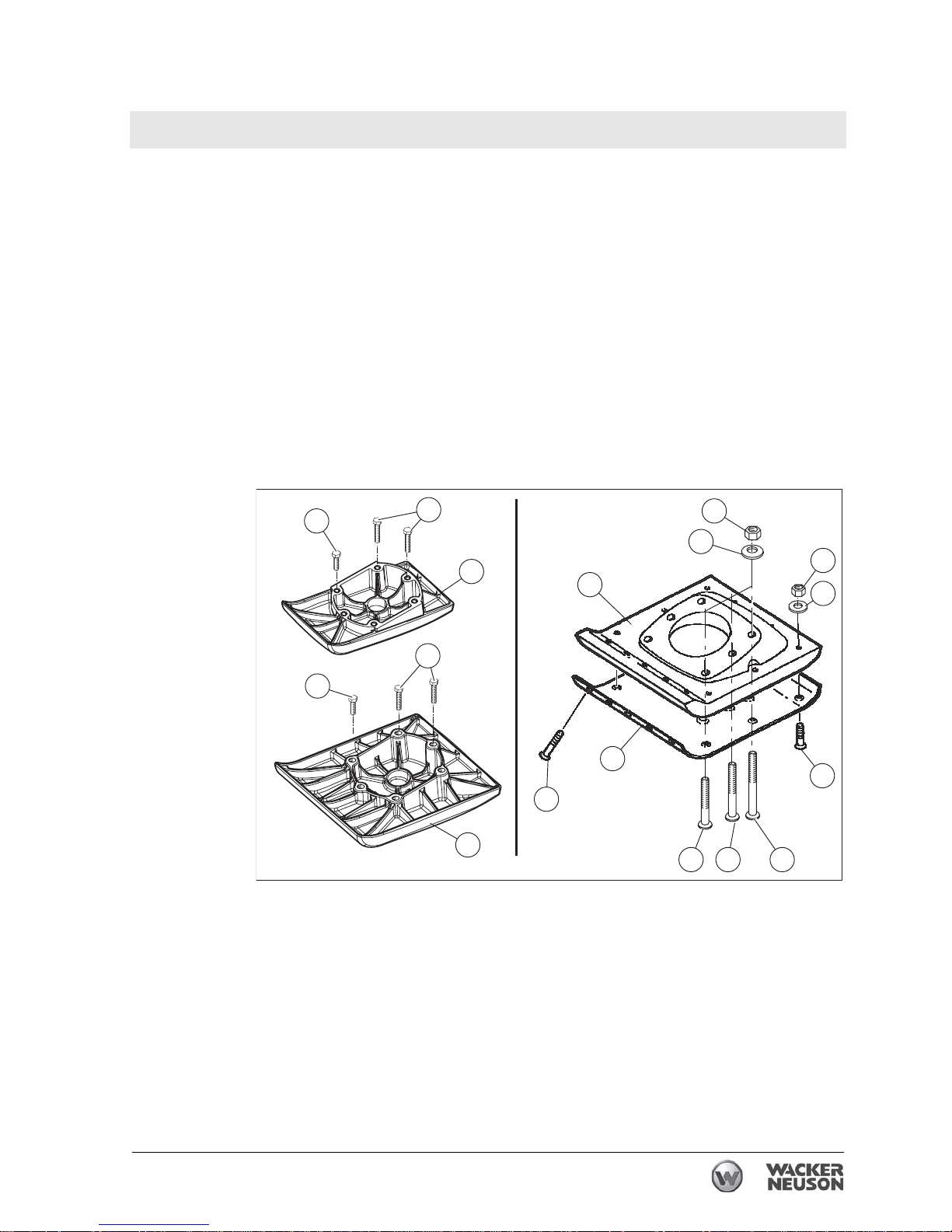
Rammer Repair Ramming System
wc_tx001547gb.fm 87
5.2 Replacing the Ramming Shoe
Requirements
• Torque wrench
• Lifting device capable of lifting the machine
Removal
Perform the procedure below to remove the shoe.
5.2.1 Support the machine with a lifting device capable of lifting the weight
of the machine. See chapter Technical Data for weights.
5.2.2 On machines with cast iron shoes, remove the hex head screws (a
and b) that hold the shoe (c) to the machine. For all others, remove
the lock nuts
(d) and washers (e) that hold the ramming shoe (f) and
the bottom plate
(g) to the machine.
5.2.3 Raise the machine off the shoe. Position the machine in a secure
place.
5.2.4 Remove the plow bolts
(m), (n), and (o).
5.2.5 Remove the plow bolts
(i and j), lockwashers (k), and lock nuts (l).
5.2.6 Separate the shoe (g) from the bottom plate (f).
wc_gr007519
a
d
e
k
l
f
g
i
j
c
c
b
a
b
m n o
Page 88
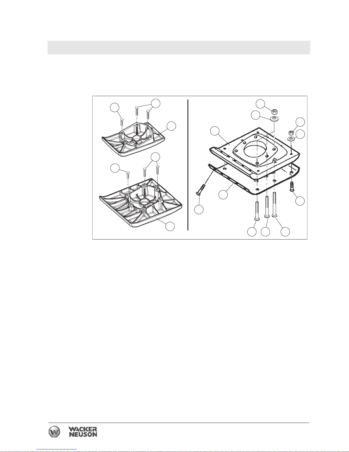
Ramming System Rammer Repair
88 wc_tx001547gb.fm
Installation
Follow the guidelines below when installing the shoes.
5.2.7 The plow bolts (m, n, and o) and (l and j) as well as hex bolts (a and b)
have different lengths. Use the longer of the bolts where needed.
5.2.8 When reusing bolts, clean the threads thoroughly before use.
5.2.9 Be sure notches of plow bolts seat in grooves of shoe.
5.2.10 Torques: (Recheck torques after first five hours of use.)
hex bol t (a): 85.5 Nm (63 ft.lbs.)
lock nuts (e): 79 Nm (58 ft.lbs.)
lock nuts (l): 24 Nm (18 ft.lbs.)
wc_gr007519
a
d
e
k
l
f
g
i
j
c
c
b
a
b
m n o
Page 89

Rammer Repair Ramming System
wc_tx001547gb.fm 89
Notes
Page 90
Ramming System Rammer Repair
90 wc_tx001547gb.fm
5.3 Spring System Cover Removal and Installation
See Graphic: wc_gr001324rm
Recommended Tools
Ratchet wrench
Torque wrench
Hex key or socket: 13 mm
Hydraulic press or
Two threaded rods and nuts: M8 x 120 mm or
Spring box tool P/N 0081423
Loctite 243
The spring system cover is under heavy pressure. It must be carefully
removed and installed using either the hydraulic press, the threaded
rod, or the spring box tool method. If the spring system cover is
removed incorrectly, the springs can eject with enough force to cause
serious injury or death!
Hydraulic Press Removal Method
5.3.1 Remove the ramming shoe per section Ramming Shoe. Separate the
ramming system from the upper machinery per section Bellows.
5.3.2 Remove all but two of the socket head cap screws that hold the spring
system cover to the spring cylinder.
5.3.3 Place the spring cylinder in a hydraulic press and position the head of
the press in firm contact with the spring system cover.
5.3.4 Lock the press and remove the remaining two screws.
5.3.5 Slowly release the press and allow the springs to expand.
5.3.6 After all the spring pressure is released, remove the spring system
cover, the gasket, and the bottom spring set.
Hydraulic Press Installation Method
5.3.7 Install the bottom spring set into the spring cylinder.
5.3.8 Place a new gasket onto the spring cylinder.
5.3.9 Center the spring cylinder, the springs, and the spring system cover
under the hydraulic press ram.
5.3.10 Align the holes in the spring system cover as close as possible with the
holes in the spring cylinder; dowels or steel rods can be placed in the
holes to act as guides.
5.3.11 Compress the springs until the spring system cover rests on the spring
cylinder.
5.3.12 Install the socket head cap screws. Apply Loctite 243 and torque the
screws to 24 Nm (18 ft.lbs.).
5.3.13 Reinstall the ramming shoe.
WARNING
Page 91
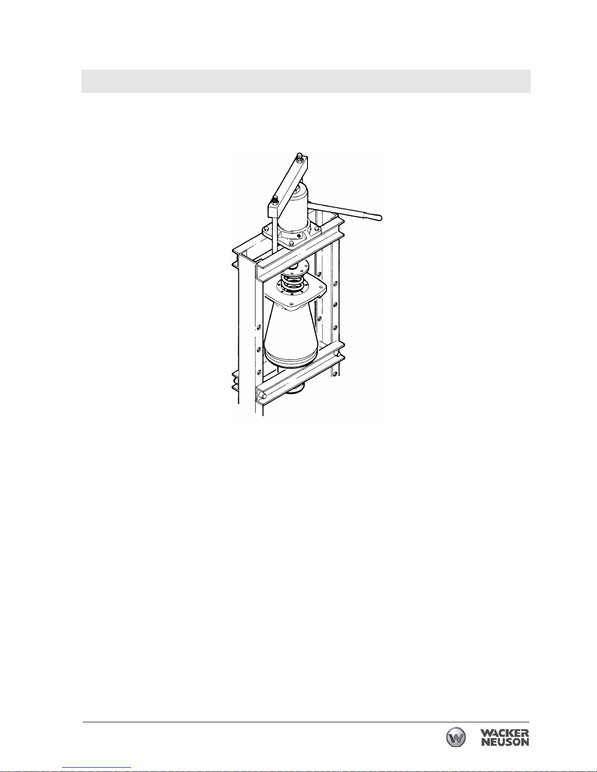
Rammer Repair Ramming System
wc_tx001547gb.fm 91
5.3.14 Attach the ramming system to the upper machinery.
wc_gr001324rm
Hydraulic Press Method
Page 92
Ramming System Rammer Repair
92 wc_tx001547gb.fm
See Graphic: wc_gr001325rm
Threaded Rod Removal Method
5.3.15 Remove the ramming shoe per section Ramming Shoe. Separate the
ramming system from the upper machinery per section Bellows.
5.3.16 Remove the two socket head cap screws that are opposite of each
other on the spring system cover.
5.3.17 Screw the two M8 x 120 threaded rods into the bottom of the spring
cylinder until they bottom out.
5.3.18 Turn the nuts down each rod until they contact the spring system
cover.
5.3.19 With the nuts holding the spring system cover, remove the remaining
screws.
5.3.20 Evenly back off both nuts until the springs have fully expanded and the
pressure is released.
Make sure the threaded rods are not turning out of the cylinder while
backing off the nuts. The spring system cover is under heavy pressure.
It must be carefully removed and installed using either the hydraulic
press, the threaded rod, or the spring box tool method. If the spring
system cover is removed incorrectly, the springs can eject with enough
force to cause serious injury or death!
5.3.21 Remove the spring system cover, the gasket, and the bottom spring
set.
Threaded Rod Installation Method
5.3.22 Install the bottom spring set into the spring cylinder.
5.3.23 Place a new gasket onto the spring cylinder.
5.3.24 Insert the two threaded rods through the opposite sides of the spring
system cover and screw them into the spring cylinder until they bottom
out.
5.3.25 Compress the springs by evenly screwing the two nuts down the
threaded rods until the spring system cover makes contact with the
spring cylinder.
5.3.26 Install the socket head cap screws. Apply Loctite 243 and torque the
screws to 24 Nm (18 ft.lbs.).
5.3.27 Reinstall the ramming shoe.
5.3.28 Attach the ramming system to the upper machinery.
WARNING
Page 93
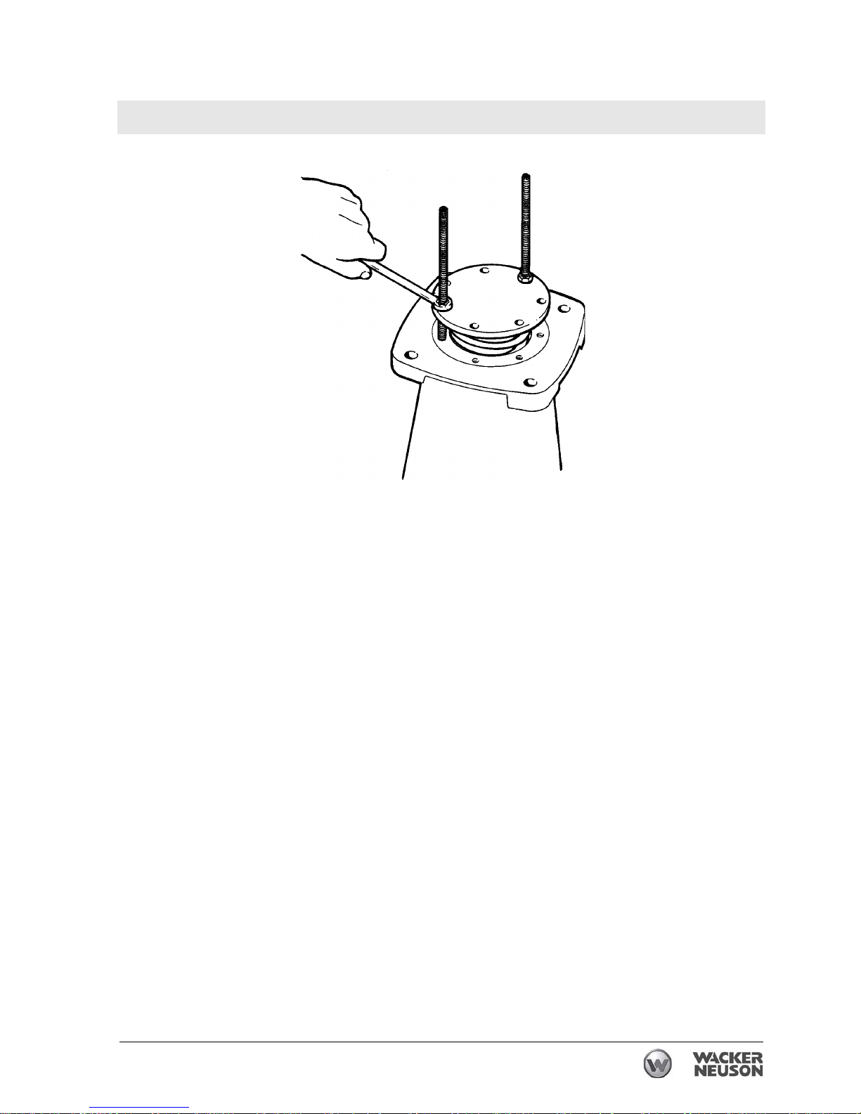
Rammer Repair Ramming System
wc_tx001547gb.fm 93
wc_gr001325rm
Threaded Rod Method
Page 94
Ramming System Rammer Repair
94 wc_tx001547gb.fm
See Graphic: wc_gr001326
Spring Box Tool Removal Method
5.3.1 Remove the ramming shoe per section Ramming Shoe. Separate the
ramming system from the upper machinery per section Bellows.
5.3.2 Align three holes in the spring box tool (a) with three socket head cap
screws in the spring system cover.
5.3.3 Remove the three socket head cap screws that align with the holes in
the spring box tool.
5.3.4 Place the spring box tool on the spring system cover. Insert the three
spring box screws (c) through the three selected holes in the spring
box tool and turn the screws into the spring cylinder until they bottom
out.
5.3.5 Turn the hex head cap screw (b) through the center of the spring box
tool until the spring box tool reaches the top of the spring box screws.
5.3.6 With the spring box tool holding the spring system cover, remove the
remaining spring system cover screws.
5.3.7 Back off the hex head cap screw until the springs have fully expanded
and the pressure is released.
The spring system cover is under heavy pressure. It must be carefully
removed and installed using either the hydraulic press, the threaded
rod, or the spring box tool method. If the spring system cover is
removed incorrectly, the springs can eject with enough force to cause
serious injury or death!
5.3.8 Remove the spring system cover, the gasket, and the bottom spring
set.
Spring Box Tool Installation Method
5.3.9 Install the bottom spring set into the spring cylinder.
5.3.10 Place a new gasket onto the spring cylinder.
5.3.11 Align three holes in the spring box tool with three holes in the spring
system cover.
5.3.12 Insert the three spring box screws through the selected holes in the
spring box tool and spring system cover.
5.3.13 Turn the spring box screws into the spring cylinder until they bottom
out.
5.3.14 Turn the hex head cap screw through the center of the spring box tool
until the spring system cover makes contact with the spring cylinder.
5.3.15 Install the socket head cap screws. Apply Loctite 243 and torque the
screws to 24 Nm (18 ft.lbs.).
5.3.16 Reinstall the ramming shoe.
5.3.17 Attach the ramming system to the upper machinery.
WARNING
Page 95
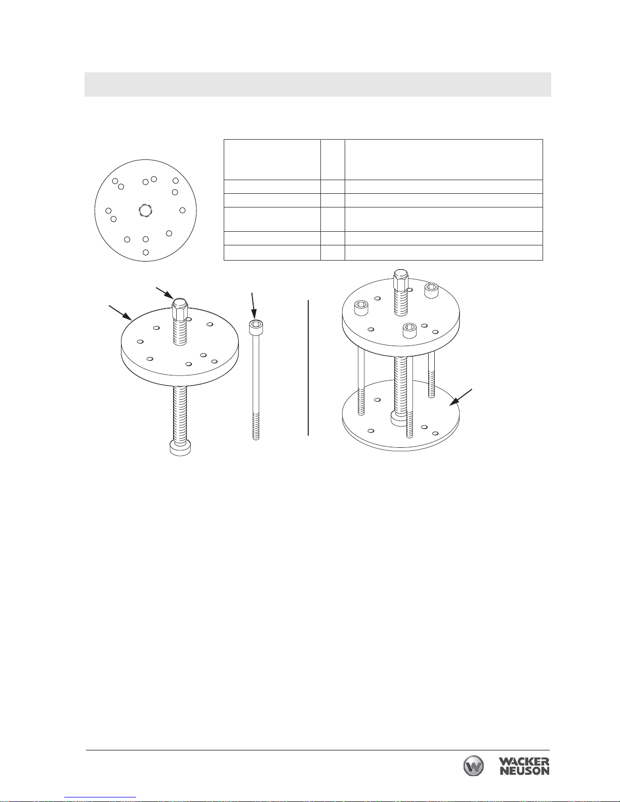
Rammer Repair Ramming System
wc_tx001547gb.fm 95
Spring Box Tool Method
a
b
d
c
wc_gr001326
4
3
1
5
3
2
4
5
1
3
4
5
2
Screw Position Qty Machine
1 2 BS45Y, BS52Y, ES45Y, ES52Y
2 2 BS60Y, GVR151Y
3 3 BS62Y, BS65y, BS600, BS650, BS700, BS60-2i,
BS70-2i, BS65V, BS60-4, DS72Y, DS720, DS70
4 3 BS92Y, BS105Y
5 3 BS500, BS50-2I, BS50-4
Schraube position st.
La posicion del tornillo
La position de vis
Page 96
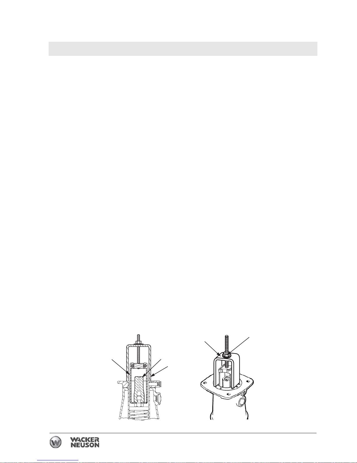
Ramming System Rammer Repair
96 wc_tx001547gb.fm
5.4 Spring System
See Graphic: wc_gr001327rm, wc_gr001328rm
Recommended Tools
Impact wrench
Socket: 32 mm or 24mm (BS 500 only) deep well
Drift pin
Torque wrench
Rubber mallet
Impact bushing puller P/N 0116816
Loctite 243 (blue)
Disassembly
5.4.1 Remove the ramming shoe and separate the ramming system from the
upper machinery.
5.4.2 Remove the spring system cover and the spring set per section Spring
System Cover Removal and Installation.
5.4.3 Loosen the nut (d) on the impact bushing puller to allow the yoke (c)
to set on the flange surface of the rammer and the jaws to reach the
bottom of the impact bushing.
5.4.4 Push the jaws (a) of the impact bushing puller over the impact bushing
(b) until it seats at the bottom of the impact bushing.
5.4.5 Tighten the nut on the impact bushing puller to remove the impact
bushing as shown in the graphic and discard.
5.4.6 Place a drift pin through the holes on the end of the ram (e) to prevent
the ram from turning.
5.4.7 Use an impact wrench to remove the locknut (k).
5.4.8 Remove the piston guide (j).
5.4.9 Remove the spring set (g) and the bushing (f) from the spring cylinder.
wc_gr001327rm
d
c
c
b
a
Page 97
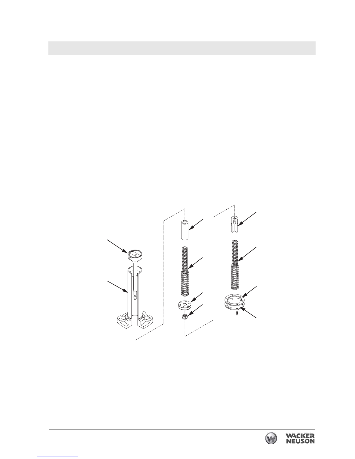
Rammer Repair Ramming System
wc_tx001547gb.fm 97
Assembly
5.4.10 Slide the ram (e) into the spring cylinder (h).
5.4.11 Reinstall the bushing (f) and the spring set (g).
5.4.12 Reinstall the piston guide (j).
5.4.13 Replace the locknut (k) and torque it to:
BS 500 - 210 Nm (155 ft.lbs.)
BS 600/700 - 250 Nm (184 ft.lbs.).
5.4.14 Press a new impact bushing (m) onto the end of the ram and seat it by
hitting the end of the impact bushing with a rubber mallet.
5.4.15 Reinstall the spring set (n).
5.4.16 Install a new gasket (o).
5.4.17 Reinstall the spring system cover (p) using one of the three methods
described in section Spring System Cover Removal and Installation.
Apply Loctite 243 and torque the screws to 24 Nm (18 ft.lbs.).
e
h
f
g
j
k
m
n
o
p
wc_gr001328rm
Page 98
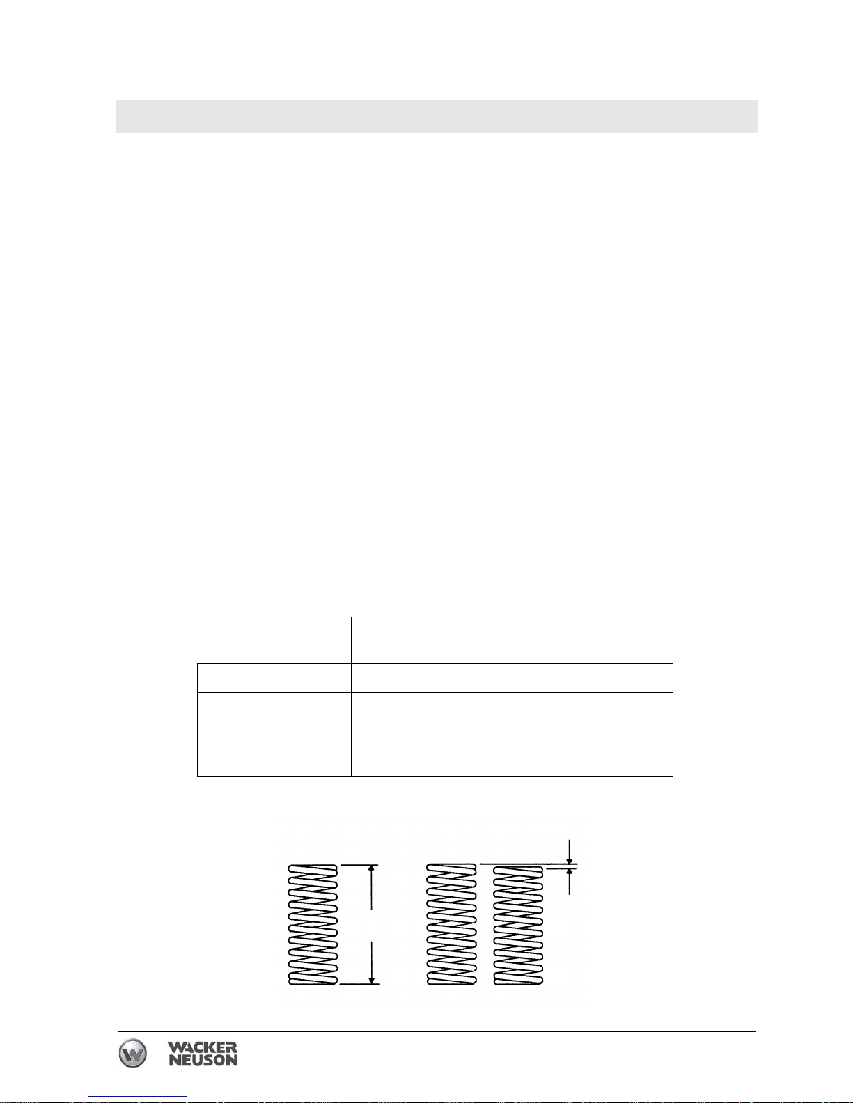
Ramming System Rammer Repair
98 wc_tx001547gb.fm
5.5 Inspecting the Spring System
See Graphic: wc_gr001329rm
Over time, the constant compression and release of the spring
pressure can cause the springs to wear out. If the rammer feels to be
hitting with less force, it is possible that the springs are worn and
should be replaced.
A broken spring causes the rammer to jump erratically. This condition
is more noticeable on hard soils. Do not run the rammer if a broken
spring is suspected. Doing so may damage other rammer parts.
Replace both the top and the bottom spring sets even if only one set is
worn or damaged.
5.5.1 Remove the springs from the cylinder and check them for minimum
spring free height and maximum spring height difference per the table
below. Replace the springs if they do not meet the given specifications.
5.5.2 If a spring has broken, inspect the inside of the spring cylinder wall for
burrs, gouges, and cracks as follows:
• Slide the piston guide inside the cylinder. Check that the piston
guide moves freely but without excessive side play.
• Hone the cylinder to remove the ridges and the burrs that were
cut into the cylinder wall by the spring movement.
• Replace the cylinder if it is badly worn.
Minimum spring free
height (a)
Maximum spring
height difference (b)
BS 500, BS 50 194 mm (7 21/32 in.) 5 mm (3/16 in.)
BS 600, BS 60
BS 700, BS 70
BS 650, BS 65V
DS 720, DS 70
217 mm (8 9/16 in.) 5 mm (3/16 in.)
wc_gr001329rm
a
b
Page 99
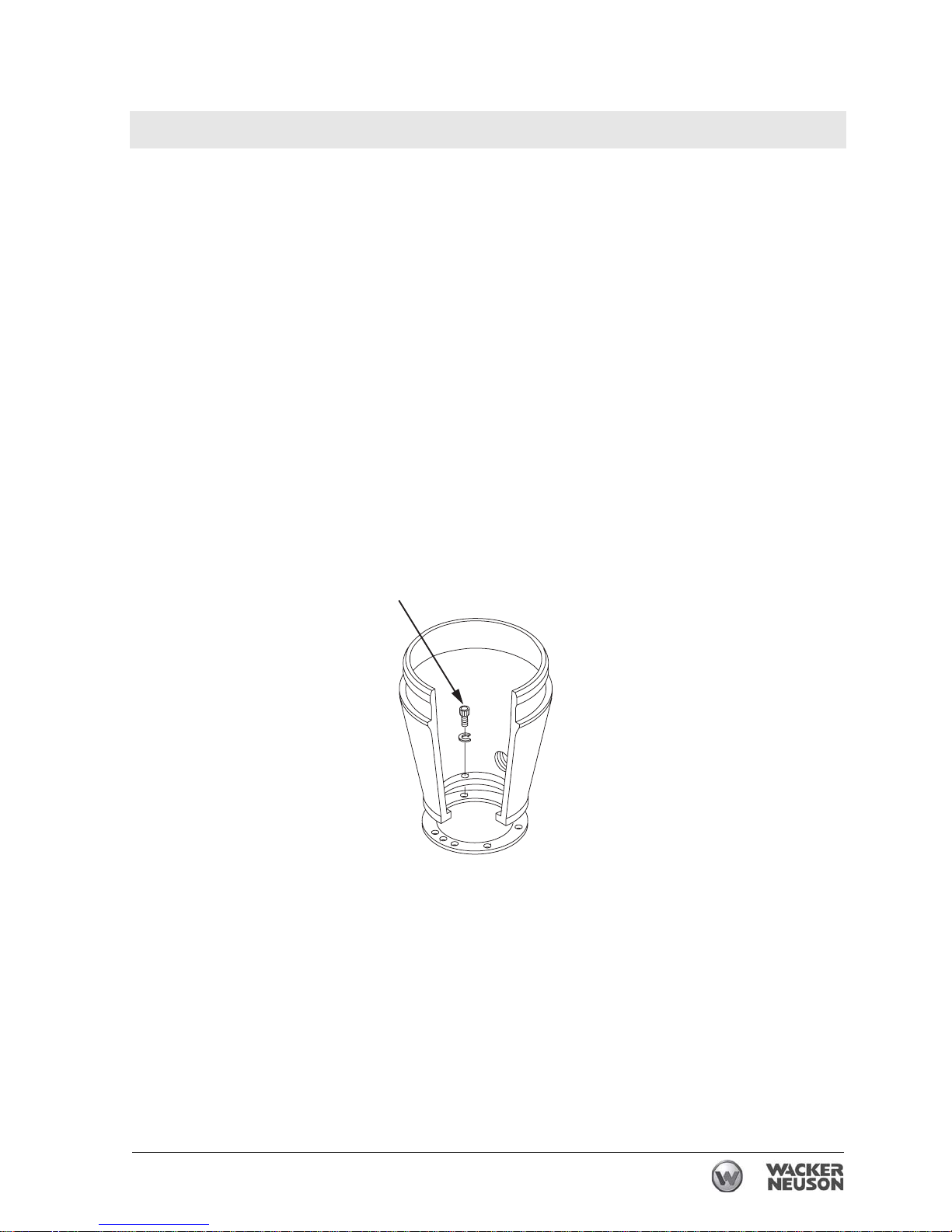
Rammer Repair Ramming System
wc_tx001547gb.fm 99
5.6 Protective Pipe
See Graphic: wc_gr001330rm
Recommended Tools
Ratchet Wrench
Torque Wrench
Extension
Hex Socket: 6 mm
Loctite 243 (Blue)
If the protective pipe becomes loose or damaged, it must be replaced
on the spring cylinder.
5.6.1 Remove the bellows following the procedures in section Bellows.
5.6.2 Remove the socket head cap screws (c). To reinstall the protective
pipe, apply Loctite 243 and torque the screws to 24 Nm (18 ft.lbs.).
5.6.3 Reassemble the rammer following the previous procedures.
c
wc_gr001330rm
Page 100

Ramming System Rammer Repair
100 wc_tx001547gb.fm
5.7 Ramming System Lubrication (BS 500/600/700/650, DS 720)
See Graphic: wc_gr001331rm
Recommended Tools
Hex Key: 8 mm
Ratchet Wrench
Torque Wrench
Extension
Sockets: 19 mm (3/4”), 27 mm (1 1/16”)
Teflon Tape
Oil for lubrication is carried throughout the ramming system by the
action of the rammer. Holes drilled in the piston allow the oil to be
distributed from the bottom of the rammer to the crankcase. Oil in the
ramming system must be maintained at the correct level to ensure the
system operates efficiently.
Check oil level:
Check the oil level in the sightglass (a) daily before starting the
rammer. When checking the oil, make sure the rammer is on a flat,
level surface. The oil level should fill 1/2–3/4 of the sightglass. Add the
oil though the fill plug (c) located in the filter housing at the top of the
rammer. See section Technical Data for oil quantity and type.
Change the ramming system oil after the first 50 hours of operation
and then after every 300 hours of use.
Oil change:
5.7.1 Remove the oil fill plug (c) and the seal ring.
5.7.2 BS 500: Remove the sightglass.
BS 600/700/650, DS720: Remove the drain plug (b).
5.7.3 Tilt the rammer back until it is resting on its handle.
5.7.4 Allow the oil to drain.
5.7.5 Wrap the sightglass threads with Teflon tape.
5.7.6 Reinstall the sightglass or the drain plug, and torque to 9.5 Nm (7
ft.lbs.).
5.7.7 Stand the rammer upright on a level surface.
5.7.8 Add oil through the fill plug. Proper ramming system lubrication is
indicated when approximately 1/2–3/4 of the sightglass is full.
NOTICE: It may take some time for the oil to filter down to the
sightglass. Use care not to overfill the ramming system. Excessively
high levels of oil can create a hydraulic lock in the ramming system.
This can result in erratic operation and cause damage to the engine
clutch, the ramming system, and the shoe.
 Loading...