

Page 1
Operator’s Manual
5200016051
Vibratory Rammer
BS50-2, BS50-2i
BS60-2, BS60-2i
BS70-2, BS70-2i
BS65-V
Type BS50-2, BS50-2i, BS60-2, BS60-2i,
Document 5200016051
Date
Revision
Language EN
BS70-2, BS70-2i, BS65-V
1116
08
Page 2

Copyright notice
© Copyright 2016 by Wacker Neuson Production Americas LLC
All rights, including copying and distribution rights, are reserved.
This publication may be photocopied by the original purchaser of the
machine. Any other type of reproduction is prohibited without express
written permission from Wacker Neuson Production Americas LLC.
Any type of reproduction or distribution not authorized by Wacker
Neuson Production Americas LLC represents an infringement of valid
copyrights. Violators will be prosecuted.
Trademarks
Manufacturer
Original instructions
All trademarks referenced in this manual are the property of their
respective owners.
Wacker Neuson Production Americas LLC
N92W15000 Anthony Avenue
Menomonee Falls, WI 53051 U.S.A.
Tel: (262) 255-0500 · Fax: (262) 255-0550 · Tel: (800) 770-0957
www.wackerneuson.com
This Operator’s Manual presents the original instructions. The original
language of this Operator’s Manual is American English.
Page 3

Rammer
Foreword
Foreword
SAVE THESE INSTRUCTIONS—This manual contains important instructions for
the machine models below. These instructions have been written expressly by
Wacker Neuson Production Americas LLC and must be followed during inst allation,
operation, and maintenance of the machines.
Machine Item Number
BS 50-2i 5200000642, 5200000643, 5200000657, 5200000658,
5200000659, 5200000660, 5200000661, 5200000687,
5200011099, 5200025428, 5200025429
BS 60-2i 5200000645, 5200000646, 5200000664, 5200000665,
5200000689, 5200000690
BS 70-2i 5200000649, 5200000650, 5200000672, 5200000673
Machine Item Number
BS 50-2 5200000641, 5200000652, 5200000653, 5200000654,
5200000655, 5200000656, 5200000685, 5200000686
BS 60-2 5200000663, 5200000688, 5200019205
BS 70-2 5200000670, 5200000671
Machine Item Number
BS 65-V 5200000669
wc_tx003550gb_FM10.fm
3
Page 4
Foreword
wc_gr010403
Rammer
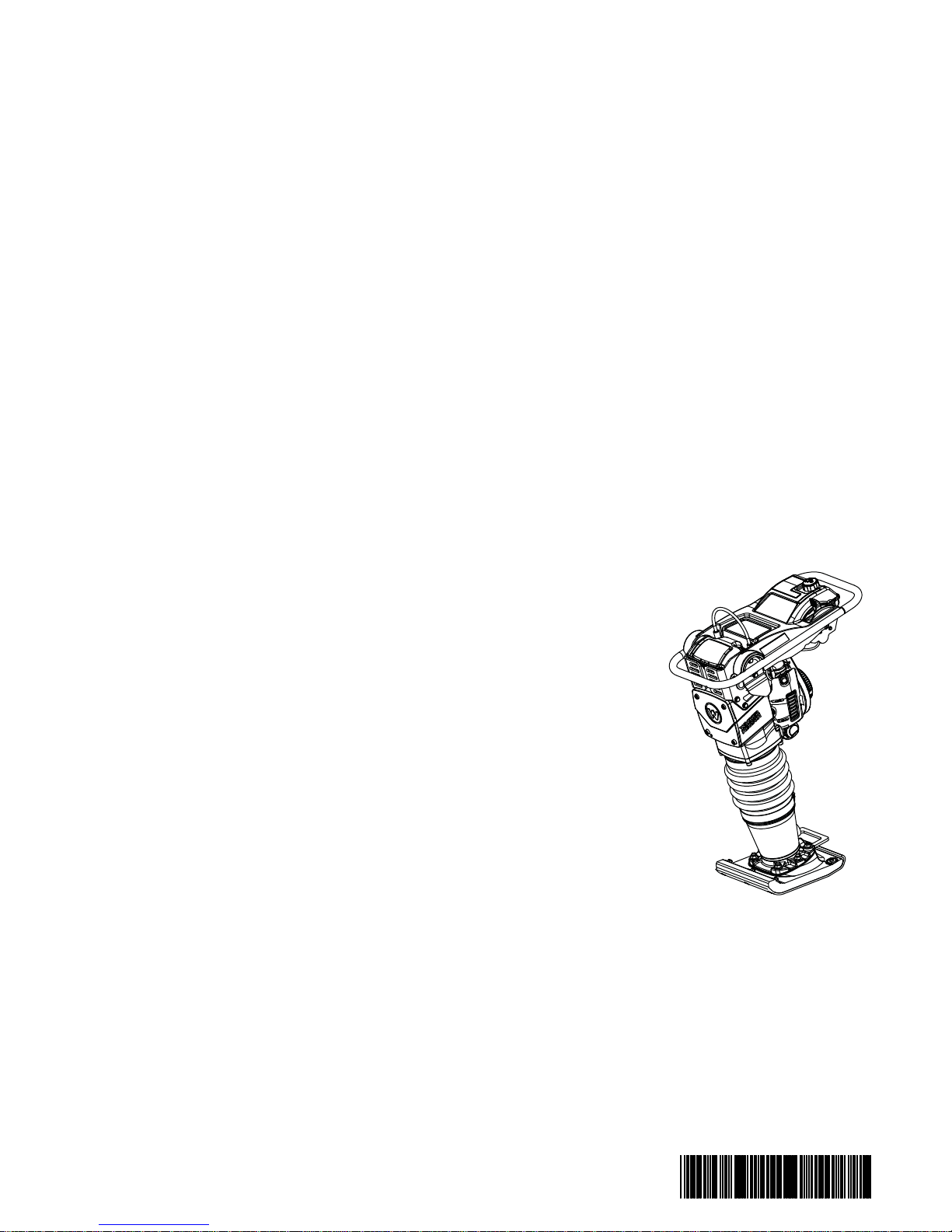
Machine
identification
Serial number
(S/N)
Machine
documentation
Expectations
for
information in
this manual
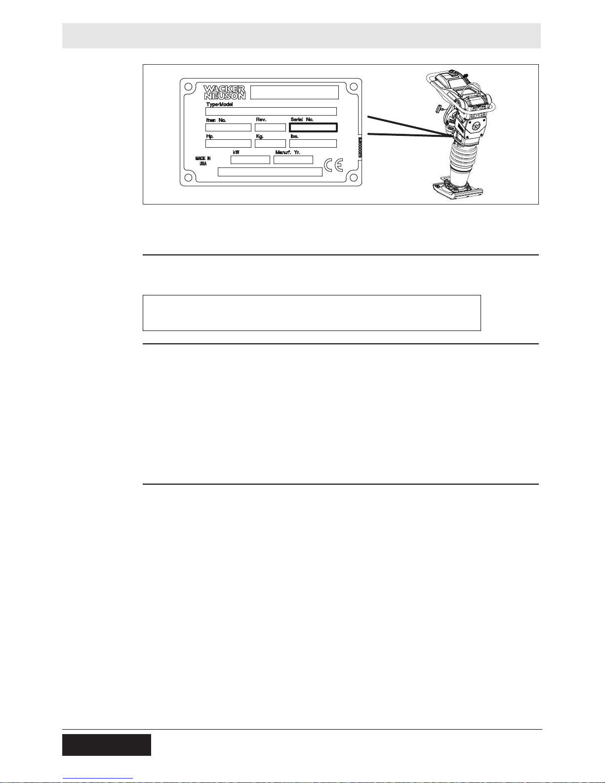
A nameplate listing the model number, item number, revision number, and serial
number is attached to this machine. The location of the nameplate is shown above.
For future reference, record the serial number in the space provided below. Y ou will
need the serial number when requesting parts or service for this machine.
Serial Number:
■ From this point forward in this documentation, Wacker Neuson Production
Americas LLC will be referred to as Wacker Neuson.
■ Keep a copy of the Operator’s Manual with the machine at all times.
■ Use the separate Parts Book supplied with the machine to order replacement
parts.
■ If you are missing either of these documents, please cont act Wacker Neuson to
order a replacement or visit www.wackerneuson.com.
■ When ordering parts or requesting service information, be prepared to provide
the machine model number, item number, revision number, and serial number.
■ This manual provides information and procedures to safely operate and
maintain the above Wacker Neuson model(s). For your own safety and to
reduce the risk of injury, carefully read, understand, and observe all instructions
described in this manual.
■ Wacker Neuson expressly reserves the right to make technical modifications,
even without notice, which improve the performance or safety standards of its
machines.
■ The information contained in this manual is based on machines manufactured
up until the time of publication. Wacker Neuson reserves th e right to change any
portion of this information without notice.
■ The illustrations, parts, and procedures in this manual refer to Wacker Neuson
factory-installed components. Your machine may vary depending on the
requirements of your specific region.
4
wc_tx003550gb_FM10.fm
Page 5

Rammer
Foreword
CALIFORNIA
Proposition
65 Warning
Laws
pertaining to
spark
arresters
Manufacturer’s
approval
Combustion exhaust, some of its constituents, and certain vehicle components
contain or emit chemicals known to the State of California to cause cancer and
birth defects or other reproductive harm.
NOTICE: State Health Safety Codes and Public Resources Codes specify that in
certain locations spark arresters be used on internal combustion engines that use
hydrocarbon fuels. A spark arrester is a device designed to prevent accidental
discharge of sparks or flames from the engine exhaust. Spark arresters are
qualified and rated by the United S t ates Forest Service for this purpose. In order to
comply with local laws regarding spark arresters, consult the engine distributor or
the local Health and Safety Administrator.
This manual contains references to approved parts, attachments, and
modifications. The following definitions apply:
■ Approved parts or attachments are those either manufactured or provided by
Wacker Neuson.
■ Approved modifications are those performed by an authorized Wacker
Neuson service center according to written instructions published by Wacker
Neuson.
■ Unapproved parts, attachments, and modifications are those that do not
meet the approved criteria.
Unapproved parts, attachments, or modifications may have the following
consequences:
■ Serious injury hazards to the operator and persons in the work area
■ Permanent damage to the machine which will not be covered under warranty
Contact your Wacker Neuson dealer immediately if you have questions about
approved or unapproved parts, attachments, or modifications.
wc_tx003550gb_FM10.fm
5
Page 6

Foreword
Notes
Rammer
6
wc_tx003550gb_FM10.fm
Page 7

EC Declaration of Conformity
Manufacturer
Wacker Neuson Production Americas LLC, N92W15000 Anthony Avenue,
Menomonee Falls, Wisconsin 53051 USA
Machine:
Product
Product category
Product function
Item number
Net installed power
Measured sound power level
Guaranteed sound power level
BS50-2
BS50-2i
Vibratory Rammer
To compact soil
5200000652, 5200000653, 5200000654, 5200000655, 5200000656,
5200000657, 5200000658, 5200000659, 5200000660, 5200000661,
5200011099, 5100014171, 5100014907, 5100016644, 5100016645,
5100016646, 5100016647, 5100016648, 5100016649, 5100016650
1.7 kW
105 dB(A)
108 dB(A)
Conformity Assessment Procedure
According to 2000/14/EC ANNEX VIII
Notified Body
Lloyds Register Verification Limited (Notified Body No 0038)
71 Fenchurch Street, London EC3M 4BS, United Kingdom
Directives and Standards
We hereby declare that this product meets and complies with the relevant regulations and
requirements of the following directives and standards:
2006/42/EC, 2000/14/EC, 2005/88/EC, 2014/30/EU, EN 500-1, EN 500-4
Authorized Person for Technical Documents
Robert Raethsel, Wacker Neuson Produktion GmbH & Co. KG, Wackerstrasse 6,
85084 Reichertshofen, Germany
Menomonee Falls, WI, USA, 08.07.2016
Keith Herr
Vice President and Managing Director
For Wacker Neuson
2017-CE-BS50-2_en_FM10 .fm
Jeff Volden
Director, Product Engineering
For Wacker Neuson
Original Declaration of Conformity
Paul Sina
Manager, Product Engineering
For Wacker Neuson
Page 8

Page 9

EC Declaration of Conformity
Manufacturer
Wacker Neuson Production Americas LLC, N92W15000 Anthony Avenue,
Menomonee Falls, Wisconsin 53051 USA
Product
Product
Product category
Product function
Item number
Net installed power
Measured sound power level
Guaranteed sound power level
BS60-2
BS60-2i
Vibratory Rammer
To compact soil
5200000663, 5100014847, 5200019205
5200000664, 5200000665, 5100014908
1.8 kW
105 dB(A)
108 dB(A)
Conformity Assessment Procedure
According to 2000/14/EC ANNEX VIII
Notified Body
Lloyds Register Verification Limited (Notified Body No 0038)
71 Fenchurch Street, London EC3M 4BS, United Kingdom
Directives and Standards
We hereby declare that this product meets and complies with the relevant regulations and
requirements of the following directives and standards:
2006/42/EC, 2000/14/EC, 2005/88/EC, 2014/30/EU, EN 500-1, EN 500-4
Authorized Person for Technical Documents
Robert Raethsel, Wacker Neuson Produktion GmbH & Co. KG, Wackerstrasse 6,
85084 Reichertshofen, Germany
Menomonee Falls, WI, USA, 28.07.16
Keith Herr
Vice President and Managing Director
For Wacker Neuson
2017-CE-BS60-2_en_FM10 .fm
Jeff Volden
Director, Product Engineering
For Wacker Neuson
Original Declaration of Conformity
Paul Sina
Manager, Product Engineering
For Wacker Neuson
Page 10

Page 11

EC Declaration of Conformity
Manufacturer
Wacker Neuson Production Americas LLC, N92W15000 Anthony Avenue,
Menomonee Falls, Wisconsin 53051 USA
Product
Product
Product category
Product function
Item number
Net installed power
Measured sound power level
Guaranteed sound power level
BS70-2
BS70-2i
Vibratory Rammer
To compact soil
5200000670, 5200000671, 5100014905, 5100016652
5200000672, 5200000673, 5100014909, 5100016653
2.0 kW
105 dB(A)
108 dB(A)
Conformity Assessment Procedure
According to 2000/14/EC ANNEX VIII
Notified Body
Lloyds Register Verification Limited (Notified Body No 0038)
71 Fenchurch Street, London EC3M 4BS, United Kingdom
Directives and Standards
We hereby declare that this product meets and complies with the relevant regulations and
requirements of the following directives and standards:
2006/42/EC, 2000/14/EC, 2005/88/EC, 2014/30/EU, EN 500-1, EN 500-4
Authorized Person for Technical Documents
Robert Raethsel, Wacker Neuson Produktion GmbH & Co. KG, Wackerstrasse 6,
85084 Reichertshofen, Germany
Menomonee Falls, WI, USA, 13.05.2016
Keith Herr
Vice President and Managing Director
For Wacker Neuson
2017-CE-BS70-2_en_FM10 .fm
Jeff Volden
Director, Product Engineering
For Wacker Neuson
Original Declaration of Conformity
Paul Sina
Manager, Product Engineering
For Wacker Neuson
Page 12

Page 13

EC Declaration of Conformity
Manufacturer
Wacker Neuson Production Americas LLC, N92W15000 Anthony Avenue,
Menomonee Falls, Wisconsin 53051 USA
Product
Product
Product category
Product function
Item number
Net installed power
Measured sound power level
Guaranteed sound power level
BS65-V
Vibratory Rammer
To compact soil
5200000669, 5100016651
2.0 kW
104 dB(A)
108 dB(A)
Conformity Assessment Procedure
According to 2000/14/EC ANNEX VIII
Notified Body
Lloyds Register Verification Limited (Notified Body No 0038)
71 Fenchurch Street, London EC3M 4BS, United Kingdom
Directives and Standards
We hereby declare that this product meets and complies with the relevant regulations and
requirements of the following directives and standards:
2006/42/EC, 2000/14/EC, 2005/88/EC, 2014/30/EU, EN 500-1, EN 500-4
Authorized Person for Technical Documents
Robert Raethsel, Wacker Neuson Produktion GmbH & Co. KG, Wackerstrasse 6,
85084 Reichertshofen, Germany
Menomonee Falls, WI, USA, 13.05.2016
Keith Herr
Vice President and Managing Director
For Wacker Neuson
2017-CE-BS65-V_en_FM10.fm
Jeff Volden
Director, Product Engineering
For Wacker Neuson
Original Declaration of Conformity
Paul Sina
Manager, Product Engineering
For Wacker Neuson
Page 14

Page 15

Rammer
Table of Contents
Foreword 3
EC Declaration of Conformity 7
1 Safety Information 17
1.1 Signal Words Used in this Manual ..................................................... 17
1.2 Machine Description and Intended Use ............................................. 18
1.3 Safety Guidelines for Operating the Machine ..................................... 19
1.4 Safety Guidelines for Lifting and Transporting the Machine ............... 20
1.5 Service Safety .................................................................................... 21
1.6 Operator Safety while Using Internal Combustion Engines ............... 23
2 Labels 24
2.1 Label Locations .................................................................................. 24
2.2 Label Meanings .................................................................................. 25
3 Lifting and Transporting 30
3.1 Lifting the Rammer ............................................................................. 30
3.2 Transporting the Rammer .................................................................. 31
4 Operation 34
4.1 Preparing the Machine for First Use ................................................... 34
4.2 Recommended Fuel ........................................................................... 35
4.3 Refueling the Machine ........................................................................ 37
4.4 Filling the Oil Tank .............................................................................. 38
4.5 Purging the Oil Lines .......................................................................... 39
4.6 Position of the Operator ..................................................................... 41
4.7 Before Starting ................................................................................... 41
4.8 Starting, Operating, and Stopping the Machine ................................. 42
4.9 Emergency Shutdown Procedure ....................................................... 44
4.10 Selecting and Adjusting the Ramming Stroke—BS 65-V ................... 45
4.11 Optional Equipment ............................................................................ 48
5 Maintenance 49
5.1 Maintaining the Emission Control System .......................................... 49
5.2 Periodic Maintenance Schedule ......................................................... 50
5.3 Servicing the Air Cleaner .................................................................... 51
wc_bo5200016051_08_FM10T
15
Page 16

Table of Contents
5.4 Checking and Changing the Ramming System Oil .............................53
5.5 Checking the Fuel Lines and Fittings ..................................................55
5.6 Maintaining the Shoe Hardware ..........................................................56
5.7 Inspecting the Machine .......................................................................57
5.8 Cleaning the Engine Cooling Fins .......................................................58
5.9 Cleaning and Checking the Spark Plug ...............................................59
5.10 Inspecting and Cleaning the Fuel Filter ...............................................60
5.11 Replacing the In-Line Fuel Filter Assembly .........................................61
5.12 Adjusting the Idle Speed .....................................................................62
5.13 Long-Term Storage .............................................................................63
5.14 Machine Disposal / Decommissioning .................................................64
Rammer
6 Troubleshooting 65
7 Technical Data 66
7.1 BS 50-2i ...............................................................................................66
7.2 BS 50-2i Operating Weight ..................................................................66
7.3 BS 60-2i ...............................................................................................67
7.4 BS 60-2i Operating Weight ..................................................................67
7.5 BS 70-2i ...............................................................................................68
7.6 BS 70-2i Operating Weight ..................................................................68
7.7 BS 50-2 ...............................................................................................69
7.8 BS 50-2 Operating Weight ..................................................................69
7.9 BS 60-2 ...............................................................................................70
7.10 BS 60-2 Operating Weight ..................................................................70
7.11 BS 70-2 ...............................................................................................71
7.12 BS 70-2 Operating Weight ..................................................................71
7.13 BS 65-V ...............................................................................................72
7.14 BS 65-V Operating Weight ..................................................................72
7.15 Sound Measurements .........................................................................73
7.16 Vibration Measurements .....................................................................74
7.17 Dimensions—BS 50-2i, BS 50-2 .........................................................75
7.18 Dimensions—BS 60-2i, BS 60-2, BS 70-2i, BS 70-2, BS 65-V ...........76
8 Emission Control Systems Information
and Warranty—Gasoline 77
8.1 Emission Control System Background Information .............................77
8.2 Limited Defect Warranty for Wacker Neuson Emission Control
Systems ...............................................................................................78
16
Page 17

Rammer
1 Safety Information
1.1 Signal Words Used in this Manual
This manual contains DANGER, WARNING, CAUTION, NOTICE, and NOTE
signal words which must be followed to reduce the possibility of personal injury,
damage to the equipment, or improper service.
This is the safety alert symbol. It is used to alert you to potential personal hazards.
► Obey all safety messages that follow this symbol.
DANGER
DANGER indicates a hazardous situation which, if not avoided, will result in death
or serious injury.
► To avoid death or serious injury from this type of hazard, obey all safety
messages that follow this signal word.
Safety Information
WARNING
WARNING indicates a hazardous situation which, if not avoided, could result in
death or serious injury.
► To avoid possible death or serious injury from this type of hazard, obey all safety
messages that follow this signal word.
CAUTION
CAUTION indicates a hazardous situation which, if not avoided, could result in
minor or moderate injury.
► To avoid possible minor or moderate injury from this type of hazard, obey all
safety messages that follow this signal word.
NOTICE: Used without the safety alert symbol, NOTICE indicates a situation
which, if not avoided, could result in property damage.
Note: A Note contains additional information important to a procedure.
wc_si000836gb_FM10.fm
17
Page 18

Safety Information
1.2 Machine Description and Intended Use
This machine is a vibratory rammer. The Wacker Neuson Rammer consists of a
gasoline or diesel engine, a clutch, a fuel tank, a spring-loaded ramming system, a
ramming shoe, and a handle. The engine transmits power through the ramming
system and ramming shoe, generating percussive impact force to compact soil.
The operator guides and controls the machine from behind using the handle.
This machine is intended to be used for compacting cohesive, mixed, and gran ular
soils in confined areas.
This machine has been designed and built strictly for the intended use described
above. Using the machine for any other purpose could permanently damage the
machine or seriously injure the operator or other persons in the area. Machine
damage caused by misuse is not covered under warranty.
The following are some examples of misuse:
■ Using the machine as a ladder, support, or work surface
■ Using the machine to carry or transport passengers or equipment
■ Using the machine as a hammer or for other demolition work
■ Attaching the machine to any other machine
■ Operating the machine outside of factory specifications
■ Operating the machine in a manner inconsistent with all warnings found on the
machine and in the Operator’s Manual
Rammer
This machine has been designed and built in accordance with the latest global
safety standards. It has been carefully engineered to eliminate hazards as far as
practicable and to increase operator safety through protective guards and labeling.
However, some risks may remain even after protective measures have been taken.
They are called residual risks. On this machine, they may include exposure to:
■ Heat, noise, exhaust, and carbon monoxide from the engine
■ Fire hazards from improper refueling techniques
■ Fuel and its fumes
■ Personal injury from improper lifting techniques or operating techniques
To protect yourself and others, make sure you thoroughly read and understand the
safety information presented in this manual before operating the machine.
18
wc_si000836gb_FM10.fm
Page 19

Rammer
1.3 Safety Guidelines for Operating the Machine
Safety Information
Operator
training
Operator
qualifications
Application
area
Before operating the machine:
■ Read and understand the operating instructions contained in all manuals
delivered with the machine.
■ Familiarize yourself with the location and proper use of all controls and safety
devices.
■ Contact Wacker Neuson for additional training if necessary.
When operating this machine:
■ Do not allow improperly trained people to operate the machine. People
operating the machine must be familiar with the potential risks and hazards
associated with it.
Only trained personnel are permitted to start, operate, and shut down the machine.
They also must meet the following qualifications:
■ have received instruction on how to properly use the machine
■ are familiar with required safety devices
The machine must not be accessed or operated by:
■ children
■ people impaired by alcohol or drugs
Be aware of the application area.
■ Keep unauthorized personnel, children, and pets away from the machine.
■ Remain aware of changing positions and the movement of other equipment and
personnel in the application area/job site.
■ Identify whether special hazards exist in the application area, such as toxic
gases or unstable ground conditions, and take appropriate action to eliminate
the special hazards before using the machine.
Be aware of the application area.
■ Do not operate the machine in areas that contain flammable objects, fuels, or
Safety
devices,
controls, and
attachments
Only operate the machine when:
■ All safety devices and guards are in place and in working order.
■ All controls operate correctly.
■ The machine is set up correctly according to the instructions in the Operator’s
■ The machine is clean.
■ The machine’s labels are legible.
To ensure safe operation of the machine:
■ Do not operate the machine if any safety devices or guards are missing or
■ Do not modify or defeat the safety devices.
■ Only use accessories or attachments that are approved by Wacker Neuson.
wc_si000836gb_FM10.fm
products that produce flammable vapors.
Manual.
inoperative.
19
Page 20

Safety Information
Rammer
Safe
operating
practices
Personal
Protective
Equipment
(PPE)
When operating this rammer:
■ Remain aware of the rammer’s moving parts. Keep hands, feet, and loose
clothing away from the rammer’s moving parts.
■ When working near the edges of pits, slopes, trenches, and platforms, always
operate the rammer in such a way that there is no possibility of it tipping over or
falling in.
When operating this rammer:
■ Do not operate a rammer in need of repair.
■ Do not tamper with or disable the function of the operating controls.
■ Do not leave the rammer running unattended.
■ Do not consume the operating fluids used in this machine. Depending on your
machine model, these operating fluids may include water, wetting agents, fuel
(gasoline, diesel, kerosene, propane, or natural gas), oil, coolant, hydraulic fluid,
heat transfer fluid (propylene glycol with additives), battery acid, or grease.
Wear the following Personal Protective Equipment (PPE) while operating this
machine:
■ Close-fitting work clothes that do not hinder movement
■ Safety glasses with side shields
■ Hearing protection
■ Safety-toed footwear
After Use
■ Stop the engine when the machine is not being operated.
■ Close the fuel valve on engines equipped with one when machine is not being
operated.
■ Ensure that the machine will not tip over, roll, slide, or fall when not being
operated.
■ Store the machine properly when it is not being used. The machine should be
stored in a clean, dry location out of the reach of children.
1.4 Safety Guidelines for Lifting and Transporting the Machine
When lifting the machine:
■ Make sure slings, chains, hooks, ramps, jacks, forklifts, cranes, hoists, and any
other type of lifting device used is attached securely and has enough weightbearing capacity to lift or hold the machine safely. See chapter Technical Data
for machine weight.
■ Remain aware of the location of other people when lifting the machine.
■ Only use the lifting points and tie-downs described in the Operator’s Manual.
■ Make sure the transporting vehicle has sufficient load capacity a nd platform size
to safely transport the machine.
To reduce the possibility of injury:
■ Do not stand under the machine while it is being lifted or moved.
■ Do not get onto the machine while it is being lifted or moved.
20
wc_si000836gb_FM10.fm
Page 21

Rammer
1.5 Service Safety
Safety Information
Service
training
Precautions
Before servicing or maintaining the machine:
■ Read and understand the instructions contained in all manuals delivered with
the machine.
■ Familiarize yourself with the location and proper use of all controls and safety
devices.
■ Only trained personnel shall troubleshoot or repair problems occurring with the
machine.
■ Contact Wacker Neuson for additional training if necessary.
When servicing or maintaining this machine:
■ Do not allow improperly trained people to service or maintain the machine.
Personnel servicing or maintaining the machine must be familiar with the
associated potential risks and hazards.
When servicing or maintaining the machine:
■ Read and understand the service procedures before performing any service to
the machine.
■ All adjustments and repairs must be completed before operating the machine.
Do not operate the machine with a known problem or deficiency.
■ All repairs and adjustments shall be completed by a qualified technician.
■ Turn off the machine before performing maintenance or making repairs.
■ Remain aware of the machine’s moving parts. Keep hands, feet, and loose
clothing away from the machine’s moving parts.
■ Re-install the safety devices and guards after repair and maintenance
procedures are complete.
Machine
modifications
When servicing or maintaining the machine:
■ Use only accessories/attachments that are approved by Wacker Neuson.
When servicing or maintaining the machine:
■ Do not defeat safety devices.
■ Do not modify the machine without the express written approval of Wacker
Neuson.
wc_si000836gb_FM10.fm
21
Page 22

Safety Information
Rammer
Replacing
parts and
labels
Cleaning
Personal
Protective
Equipment
(PPE)
■ Replace worn or damaged components.
■ Replace all missing and hard-to-read labels.
■ When replacing electrical components, use components that are identical in
rating and performance to the original components.
■ When replacement parts are required for this machine, use only Wacker
Neuson replacement parts or those p arts equivalent to the original in all types of
specifications, such as physical dimensions, type, strength, and material.
When cleaning and servicing the machine:
■ Keep the machine clean and free of debris such as leaves, paper, cartons, etc.
■ Keep the labels legible.
When cleaning the machine:
■ Do not clean the machine while it is running.
■ Never use gasoline or other types of fuels or flammable solvents to clean the
machine. Fumes from fuels and solvents can become explosive.
Wear the following Personal Protective Equipment (PPE) while servicing or
maintaining this machine:
■ Close-fitting work clothes that do not hinder movement
■ Safety glasses with side shields
■ Hearing protection
■ Safety-toed footwear
Safe service
practices
In addition, before servicing or maintaining the machine:
■ Tie back long hair.
■ Remove all jewelry (including rings).
■ Do not alter engine speeds. Run the engine only at speeds specified in
Technical Data.
■ Do not operate the machine without an air cleaner.
■ Disconnect the spark plug before servicing to avoid accidental start-up.
■ Do not crank a flooded engine with the spark plug re moved. F uel trapped in the
cylinder will squirt out the spark plug opening.
■ Do not test for spark if the engine is flooded or the smell of gasoline is present.
A stray spark could ignite the fumes.
22
wc_si000836gb_FM10.fm
Page 23

Rammer
Safety Information
1.6 Operator Safety while Using Internal Combustion Engines
WARNING
Internal combustion engines present special hazards during operation and fueling.
Failure to follow the warnings and safety standards could result in severe injury or
death.
► Read and follow the warning instructions in the engine owner’s manual and the
safety guidelines below.
DANGER
Exhaust gas from the engine contains carbon monoxide, a deadly poison.
Exposure to carbon monoxide can kill you in minutes.
► NEVER operate the machine inside an enclosed area, such as a tunnel, unless
adequate ventilation is provided through such items as exhaust fans or hoses.
Operating
safety
Refueling
safety
When running the engine:
■ Keep the area around the exhaust pipe free of flammable materials.
■ Check the fuel lines and the fuel tank for leaks and cracks before starting the
engine. Do not run the machine if fuel leaks are present or the fuel lines are
loose.
When running the engine:
■ Do not smoke while operating the machine.
■ Do not run the engine near sparks or open flames.
■ Do not touch the engine or muffler while the engine is running or immediately
after it has been turned off.
■ Do not operate a machine when its fuel cap is loose or missing.
■ Do not start the engine if fuel has spilled or a fuel odor is present. Move the
machine away from the spill and wipe the machine dry before starting.
When refueling the engine:
■ Clean up any spilled fuel immediately.
■ Refill the fuel tank in a well-ventilated area.
■ Re-install the fuel tank cap after refueling.
■ Do not smoke.
■ Do not refuel a hot or running engine.
■ Do not refuel the engine near sparks or open flames.
■ Use suitable tools for refueling (for example, a fuel hose or a funnel).
■ Do not refuel if the machine is positioned in a truck fitted with a plastic bed liner.
Static electricity can ignite the fuel or fuel vapors.
wc_si000836gb_FM10.fm
23
Page 24

Labels
wc_gr010404
A A
F
M
M
E
E
H
H
K
K
D
D
L
L
B
B
G G
J
C
C
BS 50-2i/BS 60-2i/BS 70-2i BS 50-2/BS 60-2/BS 70-2, BS 65-V
N
R
2 Labels
2.1 Label Locations
Rammer
BS 65-V
P
O
Q
24
wc_gr011507
wc_si000837gb_FM10.fm
Page 25

Rammer
wc_sy5200000316
2.2 Label Meanings
A
wc_sy5200000315
Labels
DANGER
Asphyxiation hazard.
■ E ngi ne s em it ca rb on mono xid e.
■ Do not run the machine indoors or in an enclosed area
unless adequate ventilation, through such items as
exhaust fans or hoses, is provided.
■ No sparks, flames, or burning objects near the
machine.
■ Stop the engine before refueling.
WARNING
■ To reduce the risk of hearing loss, always wear hear-
ing protection when operating this machine.
■ Read the Operator’s Manual.
To start the machine:
1. Move the throttle to the IDLE position.
2. Push the purge bulb 10 times.
3. Close the choke.
4. Pull the starter rope until engine starts.
5. Move the throttle to the FAST position.
To stop the machine:
1. Move the throttle past the SLOW position.
For optimal control, performance, and minimal han d/arm
vibration, grasp the handle as shown.
wc_si000837gb_FM10.fm
25
Page 26

Labels
AVERTISSEMENTAVERTISSEMENT
Los resortes son comprimidos. Con el fin de evitar
la expulsion de los resortes, consulte el Manual de
Reparaciones para las instrucciones de desmontaje
correcto.
The springs are compressed. In order to avoid ejection
of the springs, refer to Repair Manual for proper
disassembly instructions.
Les ressorts sont sous pression. Afin d'eviter
l'ejection des ressorts, consulter le Manuel de
Reparation pour les instructions de demontage correct.
ADVERTENCIAADVERTENCIA
118859118859
WARNINGWARNING
EMISSION CONTROL INFORMATION
This Engine/Equipment
Meets U.S. EPA EXH/EVP
REGS for
Emission Compliance Period:
300 Hours OC
EF: FW1XS.080RMR
2015
DOM
5200024289XXXXX
5200024438XXXXX
EU CERT NO:
e1*97/68SH3-IA*2012/46*0185*03
DOM
ENGINE INFORMATION
DISPLACEMENT: 80 CC
5200014890XXXXX5200014890XXXXX
CHN TYPE APPROVAL NO:CHN TYPE APPROVAL NO:
CN FD QI 0 E09 01 0001-00CN FD QI 0 E09 01 0001-00
DOMDOM
ENGINE INFORMATIONENGINE INFORMATION
DISPLACEMENT: 80 CCDISPLACEMENT: 80 CC
B
Rammer
WARNING
Springs are compre ssed . Rele ase cover slowly to a void
spring ejection.
See the Repair Manual for proper disassembly
instructions.
C
DOM
This Engine/Equipment
Meets U.S. EPA EXH/EVP
REGS for
Emission Compliance Period:
300 Hours OC
EMISSION CONTROL INFORMATION
2015
EF: FW1XS.080RMR
DOM
ENGINE INFORMATION
DISPLACEMENT: 80 CC
EU CERT NO:
e1*97/68SH3-IA*2012/46*0185*03
5200024289XXXXX
5200024438XXXXX
Emission control information
This engine/equipment meets U.S. EPA exhaust/
evaporative regulations for 2015.
Engine family: FWIXS.080RMR
Emission compliance period: 300 hours (heavy use)
Engine information
Displacement: 80cc
This label also includes the EU Certification Number:
e1*97/68SH3-IA*2012/46*0185*03
Engine information
Displacement: 80cc
This label also includes CHN Type Approval Number:
CN FD Q1 0 E09 01 0001-00
26
wc_si000837gb_FM10.fm
Page 27

Rammer
5200015661
5200000314
D
E
Labels
Guaranteed sound power level in dB(A)
Wacker Neuson label
Use only clean, filtered fuel.
F
Turtle = Idle/slow engine speed
Rabbit = Full/fast engine speed
G
5200000314
1. Move the throttle to the IDLE position.
2. Close the choke.
H
wc_si000837gb_FM10.fm
27
Page 28

Labels
JASO FD
ISO-L-EGD
TC-W3
Operation of This Equipment May Create Sparks That Can Start Fires
Around Dry Vegetation. A Spark Arrestor May be Required. The
Operator Should Contact Local Fire Agencies For Laws or Regulations
Relating to Fire Prevention Requirements.
WARNINGWARNING
Per CAL. PRC. CODE ÿ 4442.6(a) Per CAL. PRC. CODE ÿ 4442.6(a)
5200014248
:
JASO FD
ISO-L-EGD
TC-W3
J
K
L
JASO FD
ISO-L-EGD
TC-W3
Rammer
Engine oil tank
■ Use only Wacker Neuson two-cycle or other fully syn-
thetic oil meeting the NMMA TC-W3, JASO FD, or
ISO-L-EGD specification.
Read the Operator’s Manual.
WARNING
Operation of this equipment may create sparks that can
start fires around dry vegetation. A spark arrester may
be required. The operator should contact local fire
agencies for laws or regulations relating to fire
prevention requirements.
This machine may be covered by one or more patents.
M
N
O
This spark ignition system complies with the Canadian
standard ICES-002.
■ Use only Wacker Neuson two-cycle or other fully syn-
:
JASO FD
ISO-L-EGD
TC-W3
thetic oil meeting the NMMA TC-W3, JASO FD, or
ISO-L-EGD specification.
■ A gasoline/oil ratio in a range from 50:1 to 100:1 can
be used. For optimum engine per fo rm a nce and durability , a 100:1 ratio with a fully synthetic oil meeting the
specification described above is preferred.
Adjusting tool label
Refer to Selecting Ramming Stroke and Adjusting
Ramming Stroke for explanation of this label.
Read the Operator’s Manual
28
wc_si000837gb_FM10.fm
Page 29

Rammer
2
2
1
5200012055
90 kg
(200 LBS)
P
Q
R
Labels
Locking lever label
Refer to Selecting Ramming Stroke and Adjusting
Ramming Stroke for explanation of this label.
CAUTION
Cutting hazard. Moving parts under the housing cover
can cut skin and catch clothing. Do not operate the
machine while the housing cover is open.
Lifting the rammer
Use proper lifting device (crane or hoist) with proper
lifting gear (hooks, slings and/or chains) to lift the
rammer.
Do not use the end of a boom or a fork lift tine to directly
lift a rammer.
Only lift the rammer by the lifting cable.
wc_si000837gb_FM10.fm
29
Page 30

Lifting and Transporting
a
e
wc_gr010405
3 Lifting and Transporting
3.1 Lifting the Rammer
Rammer
Requirements
Procedure
■ Lifting device (crane or hoist) capable of supporting the rammer’s weight (see
the identification plate on the rammer)
■ Lifting gear (hooks, slings, and/or chains) capable of supporting the rammer’s
weight
■ Engine stopped and cool to the touch
Perform the procedure below to lift the rammer.
1. Attach the lifting gear to the central lifting cable (a).
WARNING
Crushing hazard. Do not use the guide handle (e) to lift the rammer.
► Use only the central lifting cable to lift the rammer.
WARNING
Crushing hazard. Do not use the central lifting cable if there are any signs of cut
wires, excessive wear, or other defects.
► Always inspect the central lifting cable for wear, damage, or abuse. Replace a
damaged lifting cable immediately.
► Protect the central lifting cable from all sharp edges.
2. Lift the rammer a short distance, making sure that all connections are secure.
3. Continue lifting the rammer as required.
30
wc_tx003551gb_FM10.fm
Page 31

Rammer
3.2 Transporting the Rammer
Lifting and Transporting
Overview
Requirements
Transporting
in a vehicle
This rammer can be transported in a vehicle, or manually, depending on job site
conditions and distance to be traveled.
NOTICE: Do not tow this rammer.
■ Engine stopped and cool to the touch
■ Lifting devices and gear
■ Fuel tank drained (if transporting horizontally)
Perform the procedure below to transport the rammer in a vehicle.
WARNING
Lifting injury. This machine is too heavy to lift without mechanical assistance.
► Do not attempt to lift or carry the rammer without using appropriate lifting
devices and gear as described in topic Lifting the Rammer.
1. Lift the rammer into the transport vehicle. See topic Lifting the Rammer.
2. Secure the rammer to the transport vehicle in the upright position to prevent it
from tipping, falling, or rolling.
This procedure continues on the next page.
wc_tx003551gb_FM10.fm
31
Page 32

Lifting and Transporting
a
d
c
b
wc_gr010406
Continued from the previous page.
If the rammer cannot be secured in the upright position,
a.Drain the fuel tank to prevent fuel from leaking from the cap (c).
Lay the rammer down only as shown and tie it to the vehicle a t point s
b.
Rammer
(a)
and
(b)
.
Transporting
manually
Rollers (d) enable the rammer to be rolled from one location to another. Perform
the procedure below to transport the rammer manually.
1. Drain the fuel tank to prevent fuel from leaking from the cap.
2. Lay the rammer down as shown.
3. Raise the rammer by the lifting handle (b).
4. Roll the rammer forward or backward as needed.
32
wc_tx003551gb_FM10.fm
Page 33

Rammer
Notes
Lifting and Transporting
wc_tx003551gb_FM10.fm
33
Page 34

Operation
4 Operation
4.1 Preparing the Machine for First Use
1. Make sure all loose packaging materials have been removed from the machine.
2. Check the machine and its components for damage. If there is visible damage,
do not operate the machine! Contact your Wacker Neuson dealer immediately
for assistance.
3. Take inventory of all items included with the machine and verify that all loose
components and fasteners are accounted for.
4. Attach component parts not already attached.
5. Add fluids as needed, including fuel, engine oil, and ramming system oil.
6. On rammers with oil injection (BS 50-2i, BS 60-2i, BS 70-2i), visually check the
oil in the oil supply line for air bubbles. If air bubbles exist, purge the oil supply
line before operating the machine. See topic Purging the Oil Lines for detailed
instructions.
7. Move the machine to its operating location.
Rammer
34
wc_tx003552gb_FM10.fm
Page 35

Rammer
wc gr010452
a
b
4.2 Recommended Fuel
For rammers with oil injection (BS 50-2i, BS 60-2i, BS 70-2i)
If the rammer has a fuel tank (a) and an oil tank (b), it has oil injection—No
premixing of the gasoline and oil is required. Mixing of the gasoline and oil is
done automatically by the machine.
Fill the fuel tank with regular unleaded gasoline. Fill the oil tank with Wacker
Neuson two-cycle oil (or an equivalent). See chapter Technical Data for fuel and oil
specifications.
Operation
Use of
oxygenated
fuels
Some conventional gasolines are blended with alcohol. These gasolines are
collectively referred to as oxygenated fuels. If you use an oxygenated fuel, be sure
it is unleaded and meets the minimum octane rating requirement.
Before using an oxygenated fuel, confirm the fuel’s contents. Some states and
provinces require this information to be posted on the fuel pump.
The following is the Wacker Neuson approved percentage of oxygenates:
ETHANOL - (ethyl or grain alcohol) 10% by volume. You may use gasoline
containing up to 10% ethanol by volume (commonly referred to as E10). Gasoline
containing more than 10% ethanol (such as E15, E20, or E85) may not be used
because it could damage the engine.
If you notice any undesirable operating symptoms, try another service station, or
switch to another brand of gasoline.
Fuel system damage or performance problems resulting from the use of an
oxygenated fuel containing more than the percentages of oxygenates mentioned
above are not covered under warranty.
wc_tx003552gb_FM10.fm
35
Page 36

Operation
wc_gr011466
c
Rammer
For rammers without oil injection
(BS 50-2, BS 60-2, BS 70-2, BS 65-V, BS 65-V)
If the rammer has a fuel tank (c) but no oil tank, the engine requires a two-cycle
gasoline/oil mixture.
NOTICE: Use only the recommended gasoline/oil mixture to fuel this machine.
Using gasoline alone will severely damage the engine.
Requirements
FUEL RATIO 50:1 FUEL RATIO 100:1
Gasoline Oil Gasoline Oil Gasoline Oil Gasoline Oil
5 liters 100 ml 1 gallon 2.5 oz. 5 liters 50 ml 1 gallon 1.25 oz.
10 liters 200 ml 3 gallons 8.0 oz. 10 liters 100 ml 3 gallons 4.0 oz.
15 liters 300 ml 5 gallons 13.0 oz. 15 liters 150 ml 5 gallons 6.5 oz.
■ Use only Wacker Neuson two-cycle or other fully synthetic oil meeting the
NMMA TC-W3, JASO FD, or ISO-L-EGD specification.
■ A gasoline/oil ratio in a range from 50:1 to 100:1 can be used. For optimum
engine performance and durability , a 100:1 ratio with a fully synthetic oil meeting
the specification described above is preferred.
■ Mix regular unleaded gasoline and two-cycle engine oil in a separate container
before filling the tank.
■ Refer to the chart below for the proper quantities to use when mixing gasoline
and oil.
36
wc_tx003552gb_FM10.fm
Page 37

Rammer
wc_gr011467
BS 50-2i, BS 60-2i, BS 70-2i BS 50-2, BS 60-2, BS 70-2, BS 65-V
a
b
4.3 Refueling the Machine
Operation
Requirements
Procedure
■ Machine shut down
■ Engine cool
■ Machine standing upright on the ramming shoe
■ Fresh, clean fuel supply
Perform the procedure below to refuel the machine.
WARNING
Fire and burn hazard. Fuel and its vapors are extremely flammable.
► Keep all sources of ignition away from the machine while refueling.
► Do not refuel if the machine is positioned in a truck fitted with a plastic bed liner.
Static electricity can ignite the fuel or fuel vapors.
► Refuel only when the machine is outdoors.
► Clean up spilled fuel immediately.
1. Remove the fuel cap (a).
2. Fill the fuel tank up to the base of the neck (b).
CAUTION
Fire and health hazard. Fuel expands when heated. Expanding fuel in an over-filled
tank can lead to spills and leaks.
► Do not overfill the fuel tank.
3. Re-install the fuel cap.
Result
The machine has now been refueled.
wc_tx003552gb_FM10.fm
37
Page 38

Operation
wc_gr011417
c
b
a
d
4.4 Filling the Oil Tank
For rammers with oil injection (BS 50-2i, BS 60-2i, BS 70-2i)
If the rammer has a fuel tank (a) and an oil tank (b), it has oil injection. The oil t ank
requires oil.
Rammer
Requirements
Procedure
Result
■ Machine shut down
■ Engine cool
■ Machine standing upright on the ramming shoe
■ Wacker Neuson 2-cycle or equivalent oil
Perform the procedure below to fill the oil tank.
1. Remove the oil tank cap (c).Fill the oil tank up to the base of the neck (d).
2. Re-install the oil tank cap.
Note: Clean up any spilled oil.
The oil tank has now been filled.
38
wc_tx003552gb_FM10.fm
Page 39

Rammer
wc_gr010452
a
b
wc_gr011479
x
z
y
4.5 Purging the Oil Lines
For rammers with oil injection
(BS 50-2i, BS 60-2i, BS 70-2i)
If the rammer has a fuel tank (a) and an
oil tank (b), it has oil injection. The oil
lines may need purging.
Operation
When
Requirements
Purging the
oil supply line
As needed: when air bubbles are visible in the oil supply line or discharge line
■ Machine is stopped
■ Engine is cool to the touch
■ Oil tank is filled
■ Fresh oil (as specified in Technical Data)
■ Phillips screwdriver
■ Plastic syringe
■ Clean, dry, absorbent cloth or paper towels
Perform the procedure below to purge the oil supply line.
1. Locate the oil supply line (x) connected to the oil pump (y).
2. Loosen (open), but do not remove, the bleed screw (z). Gravity in the oil supply
line will purge trapped air.
3. When air bubbles are no longer visible in the oil supply line, retighten the bleed
screw.
4. Wipe residual oil from the supply line and oil pump.
This procedure continues on the next page.
wc_tx003552gb_FM10.fm
39
Page 40

Operation
Rammer
Continued from the previous page.
Purging the
oil discharge
line
Perform the procedure below to purge the oil discharge line.
1. Locate the oil discharge line (c).
d
c
f
c
Result
e
wc_gr012472
2. If air bubbles are visible in the oil discharge line, they must be manually purged
using the following method:
Disconnect the oil discharge line at the oil pump (d). Using a plastic syringe (e)
filled with oil, inject oil into the oil discharge line until the air bubbles are gone
and oil is visible up to the carburetor adapter fitting (f).
3. After the air bubbles have been purged, reconnect the oil discharge line. Make
sure that the connections are tight with no oil leaks.
4. Wipe residual oil from the oil discharge line and fittings.
The oil lines have been purged.
40
wc_tx003552gb_FM10.fm
Page 41

Rammer
wc_gr011468
4.6 Position of the Operator
For optimal control, performance, and minimal hand/arm vibration, follow the
guidelines below when using the machine.
Grasp the handle with both hands as shown.
Stand behind the rammer, walking slowly and guiding the direction of travel as the
machine moves forward.
Note: Hand/Arm Vibration (HAV) has been optimized for the hand position shown.
Reported HA V levels are measured at position A in conformance with EN 1033 and
ISO 5349 standards.
Operation
4.7 Before Starting
1. Read safety instructions at the beginning of this manual.
2. Make sure that the fuel tank is full.
3. On machines with oil tanks:
► Make sure the oil tank is at least ¼ full.
► Check the oil lines for air.
4. Check the fuel lines and fittings.
5. Check the air filter.
6. Check the ramming system oil level.
7. Place the rammer on loose soil or gravel. DO NOT start the rammer on hard
surfaces such as asphalt or concrete.
wc_tx003552gb_FM10.fm
41
Page 42
Operation
wc_gr011422
c
1
c
2
c
3
a
b
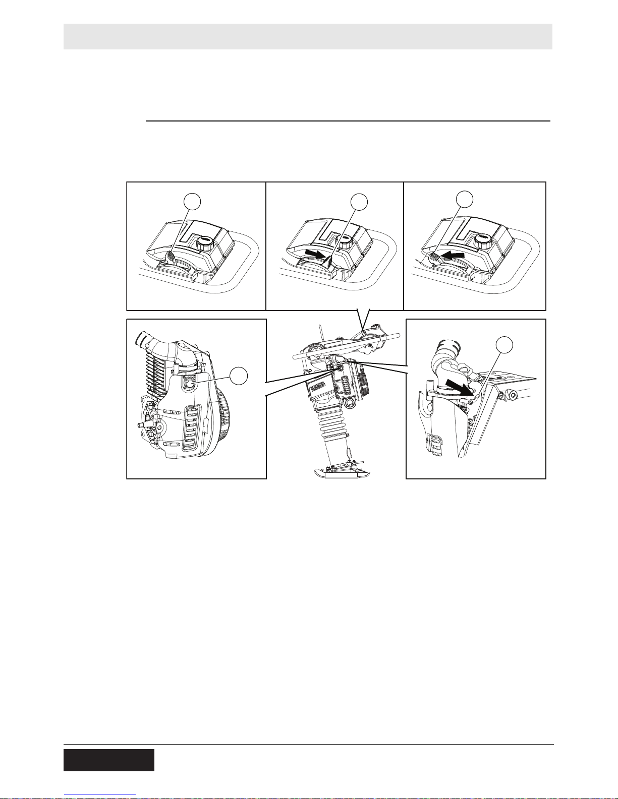
4.8 Starting, Operating, and Stopping the Machine
Rammer
Requirements
Starting the
machine
■ Rammer is in serviceable condition and has been properly maintained
■ There is fuel in the tank
Perform the procedure below to start the machine.
1. Move the throttle to the idle position (c2). This will automa tically st art the flow of
fuel.
2. Close the choke (a).
3. Pump the purge bulb (b) 6 to 10 times or until you see fuel in the bulb.
Note: The engine will not become floo ded by pumping the purge bulb more than 10
times. Pumping the purge bulb removes air from the fuel system. It does not pump
fuel into the carburetor.
4. Pull the starter rope repeatedly until the engine starts.
Multiple pulls of the starter rope (usually fewer than five) may be required to start
an engine:
■ on a new machine being operated for the first time
■ that has not been run for a long period of time (a week or more)
■ that has been run completely out of fuel
■ in cold weather conditions
This procedure continues on the next page.
42
wc_tx003552gb_FM10.fm
 Loading...