

Wacker Neuson EH 9 BL/230 Loxam, 0008429 series, EH 9 BL/115 WC, 0008735 series, 0008753 series Operator's Manual
...Page 1

www.wackergroup.com
Operator´s Manual
Electrik-hammer
EH 9 BL/...
0203039en 002
06.2006
Page 2

Page 3

Foreword
1
1. Foreword
For your own safety and protection from bodily injuries, carefully read,
understand and follow the safety instructions in this manual.
Please operate and maintain your Wacker machine in accordance with
the instructions in this manual. Your Wacker machine will reward your
attention by giving trouble-free operation and a high degree of
availability.
Replace faulty or defective components Immediately.
All rights, especially the right for copying and distribution are reserved
Copyright 2006 by Wacker Construction Equipment AG
No part of this publication may be reproduced in any form or by any
means, electronic or mechanical, including photocopying, without
express permission in writing from Wacker Construction Equipment AG.
Any type or manner of reproduction, distribution or storage on data
carriers or storage mediums not authorized by Wacker represents an
infringement of valid copyrights and will be prosecuted. We expressly
reserve the right to make technical modifications - even without due
notice - which aim at improving our machines or increasing their safety
standards.
Page 4

Table of contents
2
1. Foreword 1
2. Safety instructions 3
2.1 General Instructions ..............................................................................3
2.2 Operation ...............................................................................................3
2.3 Safety checks ........................................................................................5
2.4 Maintenance ..........................................................................................6
2.5 Transport ...............................................................................................6
2.6 Maintenance checks ..............................................................................6
3. Technical data 7
4. Description 9
4.1 Application .............................................................................................9
4.2 Putting into operation ............................................................................9
4.3 During operation ....................................................................................9
4.4 Disassembly ........................................................................................10
4.5 Assembly .............................................................................................11
5. Maintenance 12
5.1 Maintenance schedule ........................................................................12
5.2 Maintenance and lubrication ...............................................................12
6. Malfunction 13
6.1 Equipment failure ................................................................................13
7. Electric wiring diagram 14
8. Labels 15
9. Disposal 16
9.1 Environmentally friendly reuse ............................................................16
EC - Conformity Certificate 17
DIN EN ISO 9001 CERTIFICATE 19
Page 5

Drilling and breaking hammers Safety instructions
SV00046GB.fm 3
2. Safety instructions
for the use of drilling and breaking hammers with electric drive
2.1 General Instructions
2.1.1 Drilling and breaking hammers may only be operated by persons who
∗ are at least 18 years of age,
∗ are physically and mentally fit for this job,
∗ have been instructed in operating drilling and breaking hammers and
proven their ability for the job to the employer
∗ may be expected to carry out the job they are charged with carefully.
The persons must be assigned the job of operating drilling and
breaking hammers by the employer.
2.1.2 Drilling and breaking hammers are to be applied for their proper use.
Both the manufacturer’s operating instructions and these safety
instructions have to be observed.
2.1.3 The persons charged with the operation of these hammers have to be
made familiar with the necessary safety measures relating to the
machine. In case of extraordinary uses, the employer shall give the
necessary additional instructions.
2.1.4 It is possible that these drilling and breaking hammers exceed the
admissible sound level of 89 dB(A). Operators must wear personal
hearing protection if the admissible assessment sound level equals or
exceeds 89 dB (A).
2.2 Operation
2.2.1 The function of operation levers or elements is not to be influenced or
rendered ineffective.
2.2.2 Make sure that the machine is connected only to voltage and
frequency as indicated on its name plate. Choose correct cross section
for extension cord.
Page 6

Safety instructions Drilling and breaking hammers
SV00046GB.fm 4
2.2.3 The operator has to switch off drilling and breaking hammers, to
disconnect them from the electric mains and to store them in such a
manner that they do not turn over be fore leaving the machines or
going on breaks.
2.2.4 Wear safety goggles in order to avoid injuries to the eyes.
2.2.5 We recommend wearing suitable working gloves.
2.2.6 Wear safety shoes while working with drilling and breaking hammers.
2.2.7 Drilling and breaking hammers are always to be operated with both
hands on the handles provided for this purpose.
2.2.8 When working with drilling and breaking hammers, especially when
carrying out drilling jobs, the operator has to have a firm stand,
particularly when working on scaffolding and ladders.
2.2.9 Drilling and breaking hammers are to be guided such that hand injuries
caused by solid objects are avoided. When carrying out demolition
jobs at elevated places, special care is required to prevent the machine
or the operator from falling.
2.2.10 Avoid body contact with earthed components. When breaking
connecting passages, make sure that there are no electric wires or gas
pipes. No one may stay in the room to which the passage is broken
through, as there is danger of injuries because of falling stones or
tools.
2.2.11 During operation the tool holder must be closed. Tools and tool holder
must be checked for wear in order to guarantee proper functioning of
holder.
2.2.12 The operation of this machine may cause broken - off pieces to be
flung away. Therefore, during operation, no one except the operator is
to come near this machine.
2.2.13 Drilling and breaking hammers have to be disconnected from the
electric mains before changing tools.
Page 7

Drilling and breaking hammers Safety instructions
SV00046GB.fm 5
2.2.14 The tools always have to be in perfect conditions.
2.2.15 Do not operate this machine in areas where explosions may occur.
2.2.16 Do not misuse the electric cable to pull or lift up the unit or to pull the
plug out of the socket. Protect cable from heat, oil and sharp edges.
2.2.17 Electric equipment and material may only be used if they comply with
the operational and local safety requirements. They must be in proper
conditions and they must be maintained in this condition.
2.2.18 Do not expose electric tools to rain. Do not use electric tools in damp
or wet surroundings.
2.3 Safety checks
2.3.1 Drilling and breaking hammers may only be operated with all safety
devices installed.
2.3.2 Before starting operation, the operator has to check that all control and
safety devices function properly.
2.3.3 Before starting operation, the overload clutch of drilling hammers has
to be checked for proper functioning.
2.3.4 Regularly check cable for damage.
2.3.5 In case of defects of the safety devices or other defects reducing the
operational safety of the drilling and breaking hammers, the supervisor
has to be informed immediately.
2.3.6 The machine must to be switched off immediately in case of defects
jeopardizing the operational safety of the equipment.
Page 8

Safety instructions Drilling and breaking hammers
SV00046GB.fm 6
2.4 Maintenance
2.4.1 Only use original spare parts. Modifications to this machine are subject
to the express approval of the Wacker Company. All liabilities shall be
refused in case of nonobservance.
2.4.2 Disconnect the drilling and breaking hammer from the electric mains
before carrying out maintenance and repair jobs.
2.4.3 Work on the electric parts of the machines may only be carried out by
skilled technicians.
2.4.4 All safety devices must be reinstalled properly immediately after
maintenance and repair jobs have been completed.
2.5 Transport
2.5.1 When being transported on vehicles, precautions have to be taken that
these hammers do not slip or turn over.
2.6 Maintenance checks
2.6.1 According to the conditions and frequency of use, drilling and breaking
hammers have to be checked for safe operation at least once every 6
months by skilled technicians, such as those found at Wacker-service
depots and have to be repaired if necessary.
Please also observe the corresponding rules and regulations valid in your
country.
Page 9

Technical data
TD00705GB.fm 7
3. Technical data
EH 9 BL/230
EH 9 BL/
230
Loxam
Item no 0008429 ... 0008917 ... 0008735 ... 0008753 ...
Length x width x height
(without tool) mm:
560 x 105 x 245
Operating weight (mass) without
tool kg:
10
Voltage V: 220 - 240 1~
Power input kW: 1,38
Minimum generator output
requirements for single
connection kW:
3,3
Current consumption A: 7,5
Frequency Hz: 50 / 60
Percussion rate electronic
control
min
-1
:
1300 - 2150
Drill speed electronic control grease Retinax LX2
Special lubricating grease Lagre spline drive SW 19 x 82,5
Kraftübertragung Schlagsystem
From motor via crank mechanism to air-percussion
system
Drive motor
Frequency converter driven three-phase AC motor,
with protective insulation
Single drill work J: 19
Breaking output (Concrete B25) kg/h: 630
Sound pressure level at
operators station
L
PA
:
93 dB(A)
The weighted effective
acceleration value, determined
according to EN ISO 5349
m/s
2
:
is 9,8
Required cable cross-section in case of cable extensions
Max. cable length m: 26 44 70 104
Cable cross-section
mm
2
:
1,5 2,5 4 6
Page 10

Technical data
TD00705GB.fm 8
EH 9 BL/115 EH 9 BL/115 WC
Item no 0008436 ... 0008734 ...
Length x width x height
(without tool) mm:
560 x 105 x 245
Operating weight (mass) without
tool kg:
10
Voltage V: 110 - 127 1~
Power input kW: 1,2
Minimum generator output
requirements for single
connection kW:
3,3
Current consumption A: 13
Frequency Hz: 50 / 60
Percussion rate electronic
control
min
-1
:
1300 - 2150
Drill speed electronic control grease Retinax LX2
Special lubricating grease Lagre spline drive SW 19 x 82,5
Kraftübertragung Schlagsystem
From motor via crank mechanism to air-percussion
system
Drive motor
Frequency converter driven three-phase AC motor,
with protective insulation
Single drill work J: 19
Breaking output (Concrete B25) kg/h: 630
Sound pressure level at
operators station
L
PA
:
93 dB(A)
The weighted effective
acceleration value, determined
according to EN ISO 5349
m/s
2
:
is 9,8
Required cable cross-section in case of cable extensions
Max. cable length m: 7 12 20 30
Cable cross-section
mm
2
:
1,5 2,5 4 6
Page 11

Description
T00755GB.fm 9
4. Description
4.1 Application
4.1.1 Wacker’s breaking hammer is commonly used in building construction,
civil engineering, facilities construction, municipal projects, concrete
plants, artificial stone plants, foundries, installation projects, and many
other applications. The breaking hammer is very well suited for
handling natural and artificial stone and every type of masonry and
concrete. Various quick-change tools facilitate chasing, chiseling,
breaking, digging, puddling, knocking, ramming, and deburring.
4.2 Putting into operation
4.2.1 Placing and removing of tool.
∗
Pull plug from electric socket.
∗
Snap out holder spring.
∗ Insert tool as far as it will go.
∗ Snap back holder spring.
Only use perfectly sharp tools with tool shank in perfect conditions. It
is advisable to lightly grease or oil tool shank and tool holder to avoid
dry running and premature excessive wear.
4.2.2 Connection
This electric hammer is powered by A. C. (single phase) (see technicla
data). A suitable plug is provided for connection.
4.3 During operation
4.3.1 Percussion rate and impact control
To reduce the power of the hammer turn knurling wheel in handle in
anti-clockwise direction (-). Turn wheel as far as it will go. To set
hammer to full power turn knurling wheel in clockwise direction (+).
Page 12

Description
T00755GB.fm 10
4.3.2 Lock button
Lock control lever by means of lock button when using the hammer for
long breaking operations. When pression on control tongue, lock
button is released.
4.3.3 Handle system at tool holder (consisting of two handle pieces)
∗ Offset handle
Than handle can be turned perpendicularly to the tool shaft direction
and according to the application requirements by approx. 270o.
Loosen the adjusting ring for turning of handle. The handle can be
adjusted in 22,5o steps by tightening the adjusting ring.
∗ Radial handle
This handle can be screwed into either the additional handle or at the
side of the housing.
4.3.4 The complete handle system can additionally be turned by 360o,
perpendicularly to the tool shaft direction. It must be tightened with the
SW13 hex of the radial handle before starting any application (approx.
14 Nm).
4.4 Disassembly
4.4.1 Tool holder/Cylinder housing
emove pin. Remove supplementary handle with holder spring from tool
holder. Remove cheese head screws. Remove tool holder, tool holder
bush and damping sleeve. Remove cylinder housing from crankcase.
Remove percussion piston.
Page 13

Description
T00755GB.fm 11
4.4.2 Crankcase
Access to rotor circlip: Remove screws, take bearing cover and crank
mechanism out of crankcase.
4.4.3 Disassembly of handle
Remove screws. Remove handle half and back handle.
4.4.4 Motor
Access to stator pack and rotor: Remove screws, remove bearing
bracket from crankcase. Remove stator pack. Then pull out O-ring and
air guiding bushing. Remove circlip and force out rotor.
4.5 Assembly
For assembly proceed in the reverse order to dismantling. The
following has to be observed in particular:
∗ All parts must be carefully cleaned and checked. Grease bearings,
crank mechanism and percussion system with special grease (see
technicla data).
∗ Clean front surfaces of cylinder housing and crankcase and seal with
Omni Visc, model 1002.
∗ Use Omnifit 230L to glue outer race of deep groove ball bearing.
∗ After completion of any kind of repairs, test-run with increasing load.
Page 14

Maintenance
T00757GB.fm 12
5. Maintenance
5.1 Maintenance schedule
5.2 Maintenance and lubrication
5.2.1 General instructions
Keep hammer and tools clean.
5.2.2 Mechanical part
∗ Every 20 hours of operation moderately grease crank mechanism and
percussion system via lubricating nipple situated on crankcase. Use
special grease (see technicla data).
∗ Check tool holder brushing for wear. The tool may have a play of max.
6 mm at a distance of approx. 200 mm from the entrance. If the
bushing is worn to a greater degree, replace it to avoid damages and
operational failures.
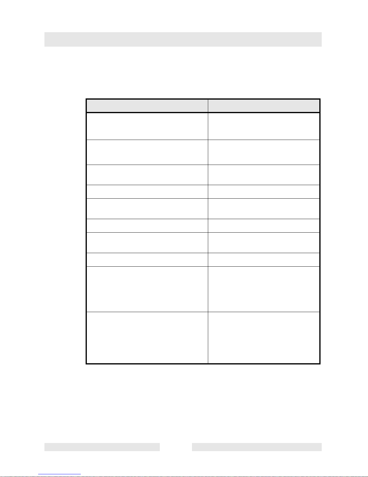
Component Maintenance work
Maintenance
interval
Feed line
Check for perfect condition - if cable defective,
replace.
daily
Miscellaneous Fan slits dirt - free - clean if necessary.
Tools
Check the shafts and cutting edges ifnecessary, sharpen, reforge or replace.
Miscellaneous Regrease via grease nipples. 20 hours
Tool holder Check for wear - change if necessary. monthly
Miscellaneous Regrease crankshaft drive. 600 hours
Page 15
Malfunction
T01040GB.fm 13
6. Malfunction
6.1 Equipment failure
Cause Remedy
for 115V machines:
Input voltage to high (>150V) or to low (<45V)
Make sure to have the correct voltage.
Check extension cable for sufficient
conductor cross section
for 230V machines:
Input voltage to high (>300V) or to low
(<170V)
Let equipment cool off
Converter temperature to high
Check supply cable incl. clamp contacts
and replace if necessary.
Supply cable interruption Replace
Switch defect
Replace cable (incl. plug) with converterswitch repair set
Broken cable between converter and switch Replace converter
Defect the converter electronics
Replace cable (incl. plug) with converterstator repair set
Broken cable between converter and stator Replace stator
Stator defect
* Let equipment run warm in warmer
environment (e.g. warm room)
* remove excessive grease from
percussion system
* replace defective components
Blocked percussion system:
* due to high grease resistance because of
low external termperatures
* due to over-greasing
* due to seizing of moving parts (e.g. due to
prolonged dry running)
Make sure to have the correct voltage.
Check extension cable for sufficient
conductor cross section
Page 16

Electric wiring diagram
SK00686GB.fm 14
7. Electric wiring diagram
white
grey
black
brown blue
Plug
Conducting
Switch
Frequency converter
Engine
Page 17
15
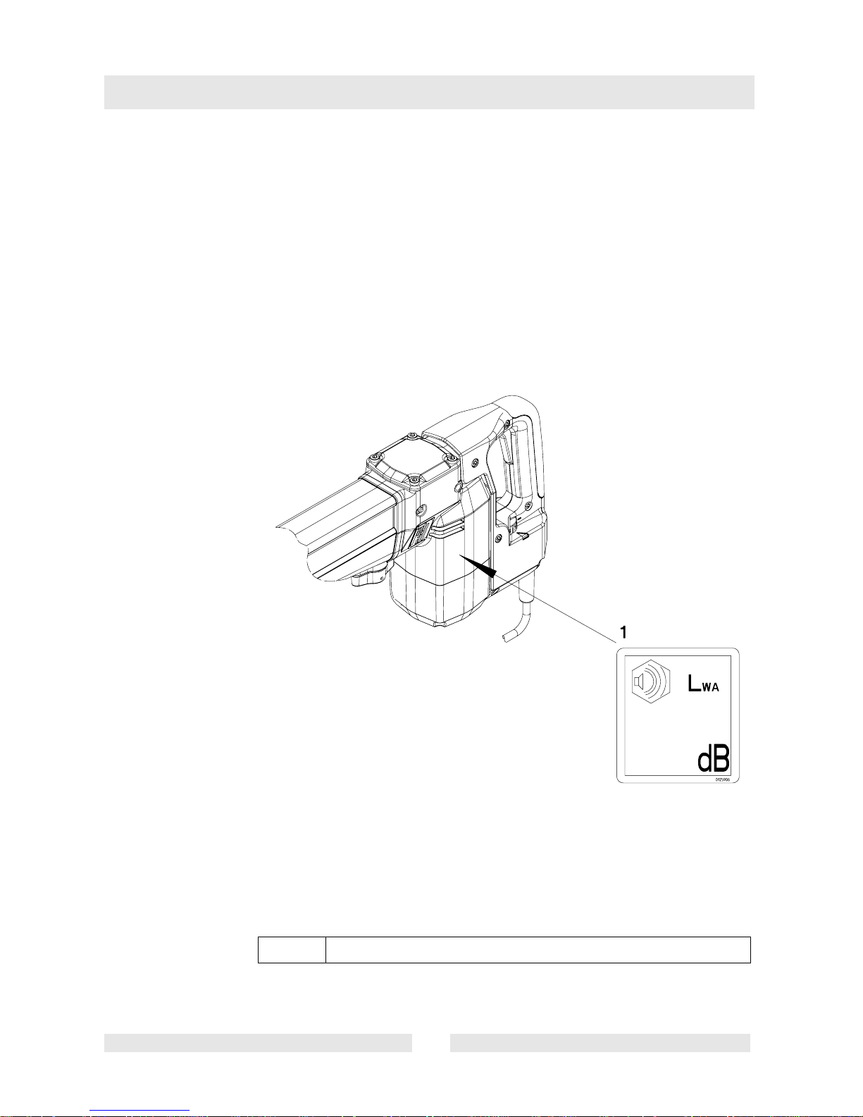
8. Labels
for the following machines:
0008429 ..., 0008732 ..., 0008735 ..., 0008736 ..., 0008737 ...,
0008738 ..., 0008753 ..., 0008917 ..., 0008918 ...
1 Decal - Sound power level
Page 18

Disposal
T01088GB.fm 16
9. Disposal
9.1 Environmentally friendly reuse
Provide for environmentally friendly reuse of the machine. Comply with
all regional regulations and directives such as the European directive
regarding old electric and electronic devices.
Do not add the device to normal waste disposal. Instead,
it should be collected separately.
Page 19

C0027004GB.fm
File certificate carefully
EC - Conformity Certificate
Wacker Construction Equipment AG, Preußenstraße 41, 80809 München
hereby certify that the construction equipment specified hereunder:
1. Category:
Breaking / Drilling hammer
2. Type:
EHB 9 BL/230
3. Equipment item number:
0008429 ..., 0008734 ..., 0008735 ...,
0008736 ..., 0008753 ..., 0008917 ...
4. Operating weight:
10 kg
has been evaluated in conformity with Directive 2000/14/EC:
and has been manufactured in accordance with the following directives:
* 2000/14/EG
* 89/336/EG
* 98/37/EG
* 73/23/EG
Conformity
assessment procedure
At the following notified
body
Measured sound
power level
Guaranteed sound
power level
Annex VIII VDE Prüf- und
Zertifizierungsinstitut
Zertifizierungsstelle
Merianstraße 28
63069 Offenbach/Main
101 dB(A) 105 dB(A)
Dr. Stenzel
Research and Development Management
Page 20

Page 21

DIN EN ISO 9001 CERTIFICATE
Page 22

Wacker Construction Equipment AG - Preußenstraße 41 - 80809 München - Tel.: +49-(0)89-3 54 02-0 - Fax: +49-(0)89-3 54 02-390
Wacker Corporation - P.O. Box 9007 - Menomonee Falls, WI 53052-9007 - Tel.: +1-(1)(262)-255-0500 - Fax: +1-(1)(262)-255-0550 - Tel.: (800)770-0957
Wacker Asia Pacific Operations-Skyline Tower, Suite 2303, 23/F, 39 Wang Kwong Road, Kowloon Bay, Hong Kong-Tel.: +852 2406 6032-Fax: +852 2406 6021
Page 23

Page 24

 Loading...