

WACKER Group LTC 4 Repair Manual

www.wackergroup.com
Light Tower
LTC 4
REPAIR MANUAL
0160487en 003
0206
0160487EN


LTC Repair Foreword
wc_tx000424gb.fm i
Operating / Parts Information
You must be familiar with the operation of this machine before you
attempt to troubleshoot or repair it. Basic operating and maintenance
procedures are described in the Operator’s Manual supplied with the
machine. Keep a copy of the Operator’s Manual with the machine at all
times. Use the separ ate Parts Book supp lied with the mach ine to order
replacement parts. If you are missing either of the documents, please
contact Wacker Corporation to order a replacement.
Damage caused by misuse or neg lect of the unit should be brough t to
the attention of the operator to prevent similar occurrences from
happening in the future.
This manual provides information and procedures to safe ly repair and
maintain the above Wacker model(s). For your own safety and
protection from injury, carefully read, understand, and observe all
instructions described in this manual. THE INFORMATION
CONTAINED IN THIS MANUAL IS BASED ON MACHINES
MANUFACTURED UP TO THE TIME OF PUBLIC ATION. WACKER
CORPORATION RESERVES THE RIGHT TO CHANGE ANY
PORTION OF THIS INFORMATION WITHOUT NOTICE.
This manual covers machines with Item Number:
0009375, 0009376, 0620017, 0620018, 0620028

Foreword LTC Repair
wc_tx000424gb.fm ii
CALIFORNIA
Proposition 65 Warning:
Diesel engine exhaust, some of its constituents, and certain vehicle
components contain or em it chemicals known to the State of California
to cause cancer and birth defects or other reproductive harm.
All rights, especially copying and distribution ri ghts, are reserved.
Copyright 2006 by Wacker Corporation
No part of this pu blication may be rep roduced in any form or by any
means, electronic or mechanical, including photocopying, without
express written permission from Wacker Corporation.
Any type of reproduction or distribution not authorized by Wacker
Corporation represents an infringement of valid copyrights, and
violators will be prosecuted. We expressly reserve the right to make
technical modifications, even without due notice, which aim at
improving our machines or their safety standards.
WARNIN
G

LTC Repair Table of Contents
wc_br0160487en_003TOC.fm 1
1. Safety Information 6
1.1 Laws Pertaining to Spark Arresters ...................................................... 6
1.2 Operating Safety .................................................................................. 7
1.3 Operator Safety while using Internal Combustion Engines .. ..... .... ..... .. 8
1.4 Towing Safety ....................................................................................... 9
1.5 Service Safety ....................................................................................10
1.6 Label Locations .................................................................................. 11
1.7 Safety and Operating Labels .............................................................. 13
2. Technical Data 19
2.1 Engine ................................................................................................ 19
2.2 Generator ........................................................................................... 20
2.3 Machine .............................................................................................. 21
3. Operation 23
3.1 Information Regarding Operation ....................................................... 23
3.2 Locating Trailer ................................................................................... 23
3.3 Leveling Trailer ................................................................................... 24
3.4 Adjusting Lights ..................................................................................24
3.5 Preparing Trailer for Towing or Lifting ................................................25
3.6 Raising Tower (Manual Winch System) ............................................. 26
3.7 Lowering Tower (Manual Winch System) ........................................... 28
3.8 Raising Tower (Power Winch System) ............................................... 30
3.9 Lowering Tower (Power Winch System) ............................................ 32
3.10 Emergency Crank Handle (Power Winch System) ............................. 33
3.11 Control Panels—Lombardini (Manual Winch System) ....................... 34
3.12 Control Panels—Lombardini (Power Winch System) ......................... 35
3.13 Control Panels—CAT (Manual Winch System) .................................. 36
3.14 Control Panel—CAT (Power Winch System) ..................................... 37
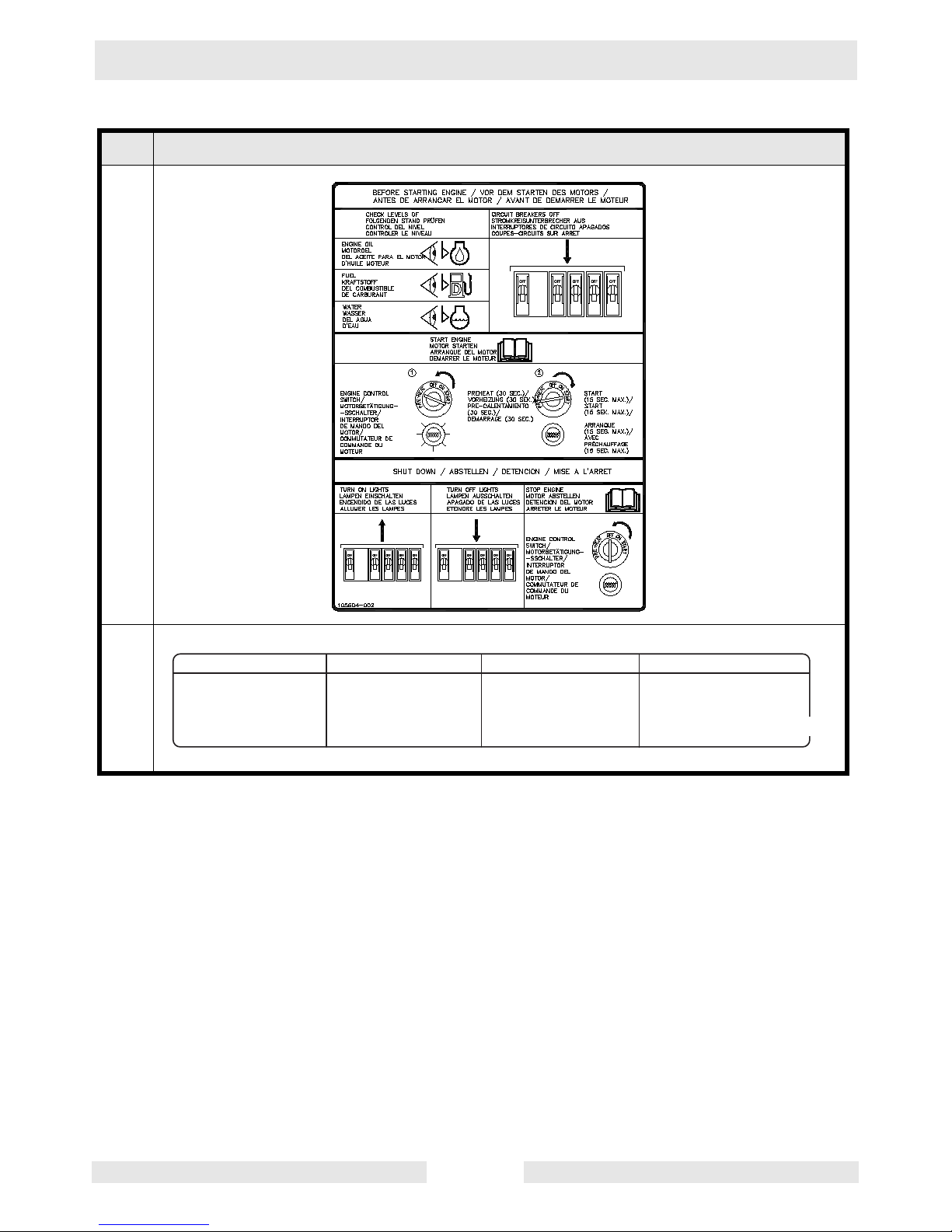
3.15 Starting—Lombardini .......................................................................... 38
3.16 Starting—CAT .................................................................................... 39
3.17 Automatic Shutdown ..........................................................................39
3.18 Operating Lights ................................................................................. 40
3.19 Stopping—Lombardini ........................................................................ 40
3.20 Stopping—CAT .................................................................................. 40
3.21 Derating .............................................................................................. 40

Table of Contents LTC Repair
wc_br0160487en_003TOC.fm 2
3.22 Receptacles—60 Hz ............................................................................41
4. Maintenance 42
4.1 Periodic Maintenance Schedule—Lombardini ....................................42
4.2 Periodic Maintenance Schedule—CAT ...............................................43
4.3 Daily Inspection ...................................................................................43
4.4 Installing / Removing Light Fixtures ....................................................44
4.5 Precautions When Replacing / Removing Bulbs .................................45
4.6 Replacing Bulbs ................................... ..... ..... .... .................................46
4.7 Air Cleaner ..........................................................................................47
4.8 Engine Oil ............................................................................................48
4.9 Generator Capacitor Excitation Schematic 60 Hz ...............................49
4.10 Schematic for 60 Hz Metal Halide 4-Light Units ..................................50
4.11 Metal Halide Schematic Components .................................................51
4.12 Engine Wiring—Lombardini 1003 ........................................................52
4.13 Engine Wiring Components—Lombardini 1003 ..................................53
4.14 Engine Control Panel Internal Wiring—Lombardini 1003 ....................54
4.15 Engine Wiring—Lombardini 903 ..........................................................55
4.16 Engine Control Panel Internal Wiring—Lombardini 903 ......................56
4.17 Engine Control Panel Components—Lombardini ................................57
4.18 Engine Wiring—Item Number: 0009376 ..............................................58
4.19 Engine Wiring—Item Number: 0620017, 0620028 ..............................59
4.20 Power Winch Schematic .....................................................................60
4.21 Trailer Wiring .......................................................................................61
5. Lombardini Engin e Troubl eshooting 62
5.1 Troubleshooting Flowcharts ................................................................62
5.2 Engine Does Not Crank—Flowchart 3A ..............................................63
5.3 Checking Keyswitch and Wiring ..........................................................64
5.4 Replacing Keyswitch ...........................................................................66
5.5 Engine Cranks But Does Not Start—Flowchart 4A .............................67
5.6 Checking Fuel System ........................................................................68
5.7 Checking Voltage to Glow Plugs (Lombardini 903 engines) ...............69
5.8 Checking Voltage to Glow Plugs (Lombardini 1003 engines) .............70
5.9 Checking Glow Plug Relay ..................................................................71
5.10 Replacing Glow Plug Relay .................................................................71
5.11 Checking Glow Plugs ..........................................................................72

LTC Repair Table of Contents
wc_br0160487en_003TOC.fm 3
5.12 Engine Shuts Down—Flowchart 5A ................................................... 73
5.13 Checking Oil Pressure and Coolant Temperature Switches .............. 74
5.14 General Engine Troubleshooting ........................................................ 75
6. Caterpillar Engine Troubleshooting 78
6.1 Troubleshooting Flowcharts ..................... ..... .... .................................78
6.2 Engine Does Not Crank—Flowchart 6A ........................................... 79
6.3 Checking Keyswitch and Wiring ......................................................... 80
6.4 Replacing Keyswitch .......................................................................... 81
6.5 Engine Cranks But Does Not Start—Flowchart 7A ............................82
6.6 Checking Fuel Flow ............................................................................ 83
6.7 Checking Glow Plug Wiring ................................................................ 84
6.8 Checking Glow Plugs ......................................................................... 84
6.9 Engine Shuts Down—Flowchart 8A ................................................... 85
6.10 Checking Oil Pressure and Coolant Temperature Switches .............. 86
6.11 General Engine Troubleshooting ........................................................ 87
7. Electrical Troubleshooting Procedures 90
7.1 Troubleshooting Methodology .............................................. ..... .... .....90
7.2 Schematic Components ..................................................................... 90
7.3 Schematic for 60 Hz Metal Halide 4-Light Units ................................. 91
7.4 Checking Continuity ...........................................................................92
7.5 Checking resistance ........................................................................... 92
7.6 Checking voltage ................................................................................ 92
7.7 Troubleshooting Flowcharts ..................... ..... .... .................................92
7.8 Lights do not Illuminate—Flowchart 1A ......................................... .....93
7.9 Lights do not Illuminate—Flowchart 1B ......................................... .....94
7.10 Lights do not Illuminate—Flowchart 1C ..............................................95
7.11 Lights do not Illuminate—Flowchart 1D ............................................. 96
7.12 Checking Engine Speed ..................................................................... 97
7.13 Checking Generator Voltage at Receptacle .......................................98
7.14 Replacing Receptacle ........................................................................99
7.15 Checking Voltage to the Main Circuit Breaker .................................. 100
7.16 Checking Voltage Between Main Circuit Breaker and Terminal Strip 102
7.17 Checking Individual Circuit Breakers ................................................ 104
7.18 Confirming a Malfunctioning Circuit Breaker .................................... 106
7.19 Checking Incoming Voltage to Control Panel Capacitor(s) .............. 107

Table of Contents LTC Repair
wc_br0160487en_003TOC.fm 4
7.20 Checking Outgoing Voltage from Control Panel Capacitor(s) ...........108
7.21 Confirming a Faulty Control Panel Capacitor ....................................109
7.22 Checking Wiring to/from Ballast(s) ....................................................110
7.23 Replacing Ballast ......................... ..... .................................................112
7.24 Restoring Rotor Magnetism (Flashing) / Checking Roto r Winding ....114
7.25 Checking Generator Capacitors ........................................................116
7.26 Alternative Capacitor Check ..............................................................117
7.27 Replacing Generator Capacitor(s) ........................... ..... .... ..... ............118
7.28 Checking Stator Windings .................................................................120
7.29 Removing/Installing Caterpillar Engine with Generator .....................122
7.30 Removing/Installing Lombardini Engine with Generator ...................124
7.31 Separating Stator Assembly from Engine/Rotor Assembly ...............126
7.32 Remounting Stator Assembly to Rotor/Engine Assembly .................128
7.33 Checking Rotor Diodes .....................................................................129
7.34 Checking Rotor Windings ..................................................................130
7.35 Removing/Installing Rotor .................................................................131
7.36 No Voltage at Receptacle—Flowchart 2A .........................................132
7.37 Checking Voltage at Receptacle .......................................................133
7.38 Checking Receptacle’s Circuit Breaker .............................................134
7.39 Troubleshooting the Power Winch ....................................................136
8. Disassembly/Assembly Procedures 139
8.1 Tools ..................................................................................................139
8.2 Ordering Parts ...................................................................................139
8.3 Reference Numbers ( ) ................................................. .... .................139
8.4 Weight Block .....................................................................................139
8.5 Light Assembly ..................................................................................140
8.6 Tower Assembly Exploded View .......................................................142
8.7 Tower Assembly List of Parts ............................................................143
8.8 Upper Mast ........................................................................................143
8.9 Mid Mast ............................................................................................146
8.10 Main Mast ..........................................................................................148
8.11 Replacing Cable and Winch on Power Winch Models ......................152
8.12 Replacing Fuel Tank ............................................... ..... .... .................154
8.13 Replacing Hour Meter ............................................. ..... .... .................156

LTC Repair Table of Contents
wc_br0160487en_003TOC.fm 5
Safety Information LTC Repair
wc_si000164gb.fm 6
1. Safety Information
This manual contains DANGER, WARNING, CAUTION, and NOTE
callouts which must be followed to reduce the possibility of personal
injury, damage to the equipment, or improper service.
This is the safety alert symbol. It is used to alert you to potential
personal injury hazards. Obey all safety messages that follow this
symbol to avoid possible injury or death.
DANGER indicates an imminently hazardous situation which, if not
avoided, will result in death or serious injury.
WARNING indicates a potentially hazardous situation which, if not
avoided, could result in death or serious injury.
CAUTION indicates a potentially hazardous situation which, if not
avoided, may result in minor or moderate injury.
CAUTION: Used without the safety alert symbol, CAUTION indicates
a potentially hazardous situation which, if not avoided, may result in
property damage.
Note: Contains additional information important to a procedure.
1.1 Laws Pertaining to Spark Arresters
Notice: State Health Safety Codes and Public Resources Codes
specify that in certain locations spark arresters be used on internal
combustion engines that use hydrocarbon fuels. A spark arrester is a
device designed to prevent accidental discharge of sparks or flames
from the engine exhaust. Spark arresters are qualified and rated by
the United States Forest Service for this purpose.
In order to comply with local laws regarding spark arresters, consult
the engine distributor or the local Health and Safety Administrator.
DANGER
WARNIN
G
CAUTION

LTC Repair Safety Information
wc_si000164gb.fm 7
1.2 Operating Safety
Familiarity and proper train ing are required for the safe operation of
equipment. Equi p me nt o pe ra te d i m properly or by untr ained personnel
can be dangerous. Read the operating instructions contained in both
this manual and the engine manual and familia rize yourself with the
location and prop er use of al l controls. In experienced op erators should
receive instruction from someone familia r with the equipment before
being allowed to operate the ma chine.
1.2.1 The area immediately surrounding the Light Tower should be clean,
neat, and free of debris.
1.2.2 ALWAYS be sure the machine is o n a firm, level surface and will not
tip, roll, slide, or fall while operating.
1.2.3 NEVER start a unit in need of repair.
1.2.4 Lower the tower when not in use, or if high winds or electrical storms
are expected in the area.
1.2.5 ALWAYS make certain the machine is well-grounded and securely
fastened to a good earthen ground per national and local regulations.
1.2.6 The tower extends up to 9 m (30 ft.). Make sure the area above the
trailer is open and clear of overhead wires and obstructions.
1.2.7 The bulbs become extremely hot in use! Allow the bulb and fixture to
cool 10–15 minutes before handling.
1.2.8 Keep the area behind the trailer clear of people while raising and
lowering the mast! Never raise, lower or turn the mast while unit is
operating!
1.2.9 The trailer must be leveled and the outriggers extended before raising
the tower. The outr iggers mu st remain extend ed while the tower is u p.
1.2.10 If for any reason any part of the mast hangs up or the winch cable
develops slack while raising or lowering the tower, STOP immediately!
Contact an authorized WACKER service representative.
1.2.11 NEVER remove the mast locking pin while the tower is up!
1.2.12 NEVER use the machin e if the insulation on the electrical cord is cut or
worn through.
1.2.13 NEVER operate the l igh ts w it ho ut th e p ro tect i ve le ns co ver i n place or
with a lens cover that is cracked or damaged!
1.2.14 NEVER adjust the mast while the unit is operating.
1.2.15 NEVER raise the mast or operate the Light Tower in high winds.
WARNIN
G

Safety Information LTC Repair
wc_si000164gb.fm 8
1.3 Operator Safety while using Internal Combustion Engines
Internal combustion eng ine s present sp ecial ha zard s during op eratio n
and fueling. Read and follow the warning instructions in the engine
owner’s manual and t he saf ety gu ideli nes belo w. Failu re to follow the
warnings and saf ety guidelines could result in severe injury or death.
1.3.1 NEVER operate the machine indoors unless exhaust fumes can be
adequately ventilated.
1.3.2 DO NOT fill or dr ain the fue l tank ne ar an open flame , wh ile smo kin g,
or while the engine is running.
1.3.3 ALWAYS refill the fuel tank in a well-ventilated area.
1.3.4 DO NOT touch or lean against hot exhaust pipes.
1.3.5 ALWAYS replace the fuel tank cap after refueling.
1.3.6 DO NOT remove radiator cap when the engine is hot . The radiator fluid
is hot and under pressure and may cause severe burns!
1.3.7 DO NOT use gasoline or other type s of fu el s or flam ma bl e so lvents to
clean parts, especially in enclosed areas. Fumes from fuels and
solvents can become explosive.
1.3.8 ALWAYS keep the area around the muffler free of debris such as
leaves, paper, cartons, etc. A hot muffler could ignite the debris and
start a fire.
DANGER

LTC Repair Safety Information
wc_si000164gb.fm 9
1.4 Towing Safety
Towing a large trailer requires special care. Both the trailer and vehicle
must be in good condition and securely fastened to each other to
reduce the possibility of an accident.
1.4.1 ALWAYS check that the hitch and coupling on the vehicle are rated
equal to, or greater than, the trailer's “gross vehicle weight rating”
(GVWR).
1.4.2 ALWAYS inspect the hitch and coupling fo r wear or dam age. DO NOT
tow the trailer using defective parts.
1.4.3 ALWAYS make sure the coupling is securely fastened to the vehicle.
1.4.4 ALWAYS check the tires on the trailer for tread wear, inflation, and
condition. Replace worn tires.
1.4.5 ALWAYS connect the safety chains.
1.4.6 ALWA YS make sure directional and traile r lights are connected and
working proper ly.
1.4.7 ALWAYS check that the l ug nu ts hol d i ng th e w he els ar e tig ht an d that
none are missing.
1.4.8 The maximum recommended speed for highway towing is 72 km/hour
(45 MPH). Recommended off-road towing speed is not to exceed 16
km/hour (10 MPH) or less depending on terrain.
1.4.9 ALWAYS refer to the applicable Department of Transportation
regulations before towing.
WARNIN
G

Safety Information LTC Repair
wc_si000164gb.fm 10
1.5 Service Safety
HIGH VOLTAGE! This unit uses high voltage circuits capable of
causing serious injury or death. Only a qualified electrician should
troubleshoot or repair electrical problems occurring in this equipment.
1.5.1 ALWAYS replace the safety devices and guards after repairs and
maintenance.
1.5.2 Before servicing the Li gh t Tower , m ake sure th e engine start switch is
turned to OFF, the circui t breakers are open (o ff), and the negative
terminal on battery is disconnected. NEVER perform even routine
service (oil/filter changes, cleaning, etc.) unless all electrical
components are shut down.
1.5.3 DO NOT allow water to accumulate around the base of the machine.
If water is present, move the machine and allow the machine to dry
before servicing.
1.5.4 DO NOT service the machine if your clothing or skin is wet.
1.5.5 ALWAYS keep hands, feet, and loose clothing away from the moving
parts on the generator and engine.
1.5.6 ALWAYS keep the machine clean and labels legible. Replace all
missing and hard-to-read labels. Labels provide important operating
instructions and warn of dangers and hazards.
1.5.7 ALWAYS make sure slings, chains, hooks, ramps, jacks and other
types of lifting devices are attached securely and have enough weightbearing capacity to lift or hold the machine safely. Always remain
aware of the location of other people around when lifting the machine.
1.5.8 ALWAYS turn off the light circuit breakers and shut down the engine
before disconnecting the light fixtures or changing the light bulbs.
WARNIN
G
LTC Repair Safety Information
wc_si000164gb.fm 11
1.6 Label Locations
Safety Information LTC Repair
wc_si000164gb.fm 12

LTC Repair Safety Information
wc_si000164gb.fm 13
1.7 Safety and Operating Labels
Wacker machines use international pictorial labels where needed.
These labels are described below:
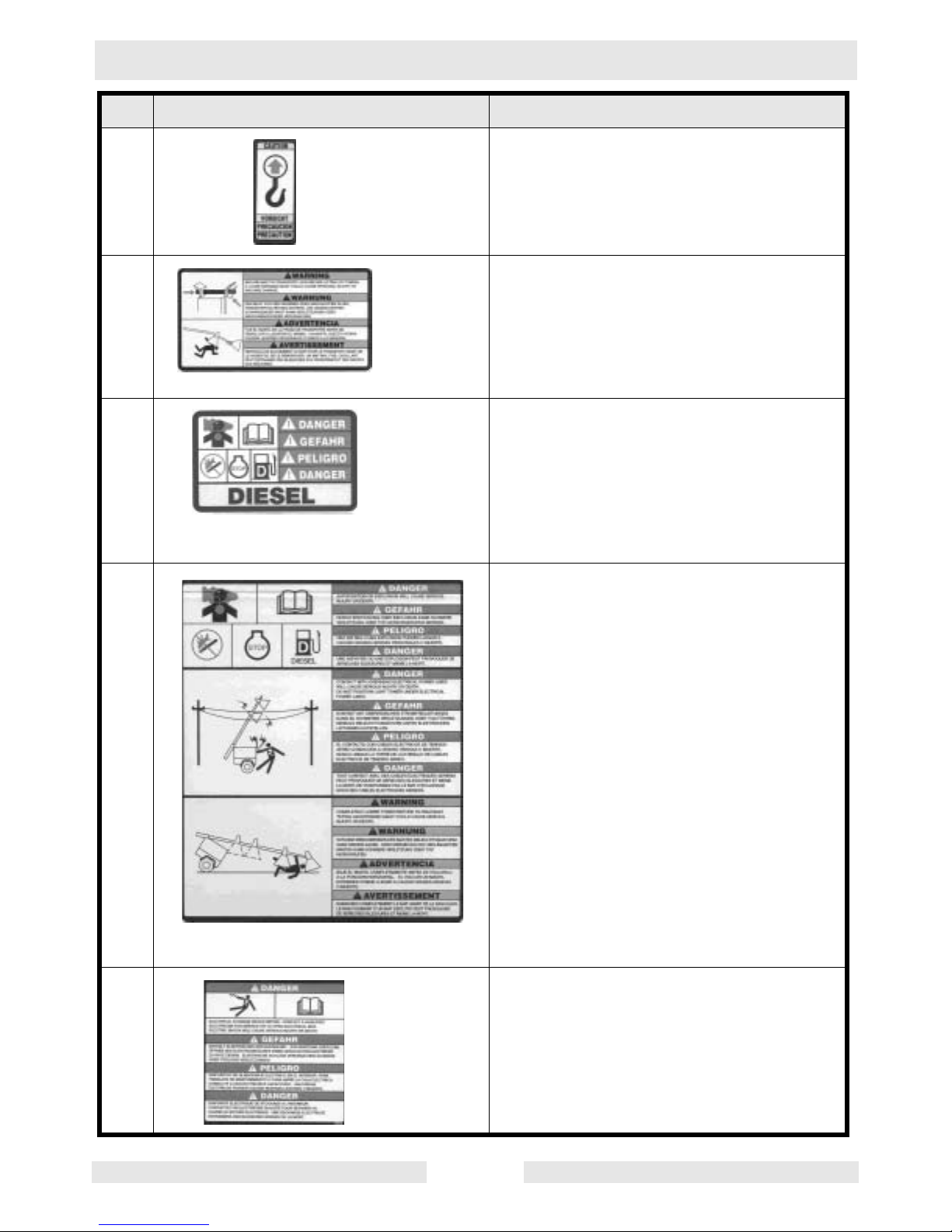
Ref. Label Meaning
A DANGER!
A non-secured, falling mast will cau s e
serious injury or death if a person is hit.
To secure mast, verify automatic locking
pin has engaged to secure tower upright.
B WARNING!
Avoid crushing are a.
C WARNING!
Completely lower tower before tilting
mast. Tilting an extended mast could
cause serious injury or death.
D DANGER!
Contact with overhead electrical power
lines will cause serious inj ury o r death.
Do not position Light Tower under
electrical power lines.
Safety Information LTC Repair
wc_si000164gb.fm 14
E CAUTION!
Lifting point
F WARNING!
Secure mast in transport lock before
lifting or towing. A loose swinging mast
could cause personal injury or machine
damage.
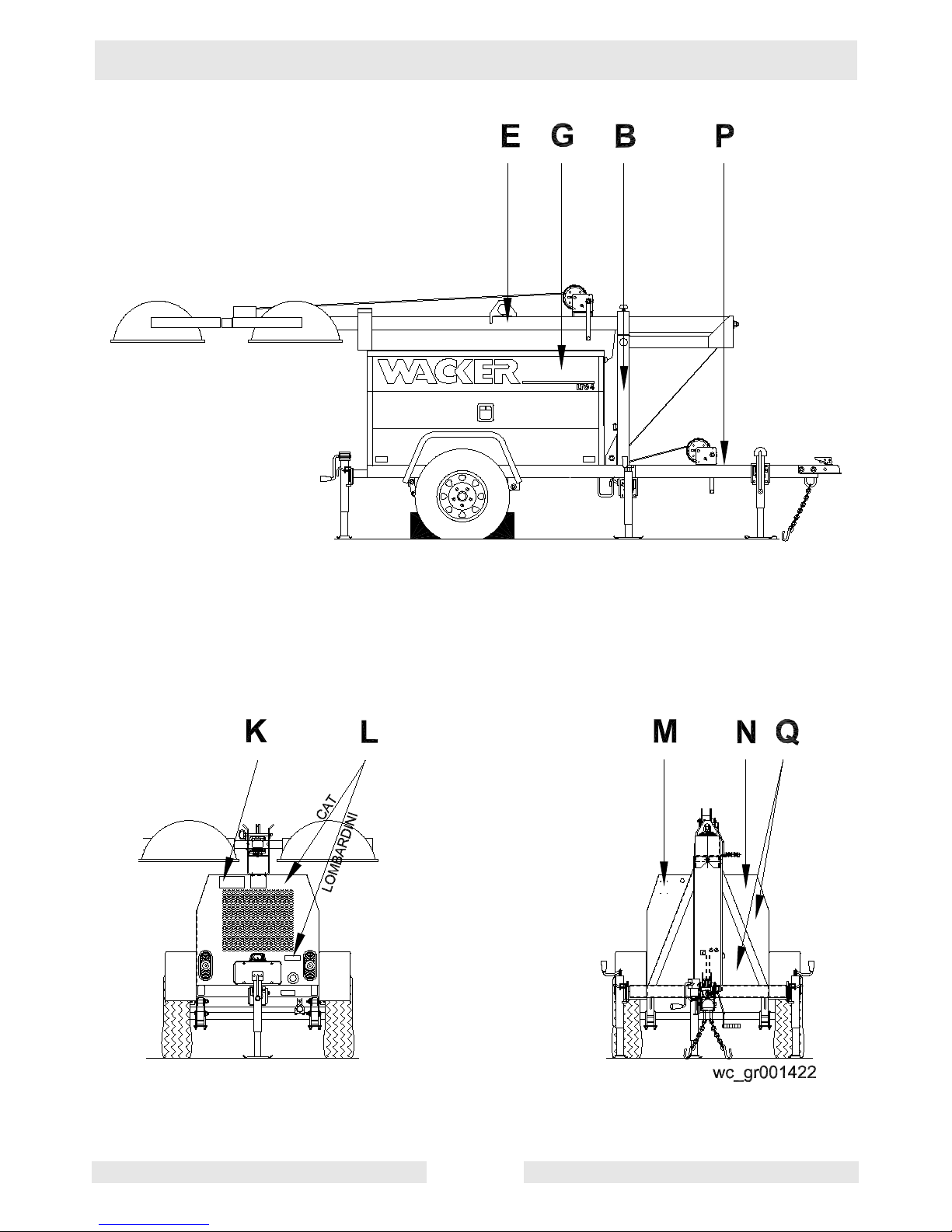
G DANGER!
Asphyxiation hazard. Read the Operator’s Manual for instructions. No sparks,
flames, or burning objects near machine.
Stop the engine before adding fuel. Use
only diesel fuel.
H DANGER!
Asphyxiation hazard. Read the Operator’s Manual for instructions. No sparks,
flames, or burning objects near machine.
Stop the engine before adding fuel. Use
only diesel fuel.
DANGER!
Contact with overhead electrical power
lines will cause serious injury or death.
Do not position Light Tower under
electrical power lines.
WARNING!
Completely lower tower before tilting
mast. Tilting an extended mast could
cause serious injury or death.
I DANGER!
Electrical storage device wit hin. Contact
a qualified electrician for service or to
open electrical box. Electric shock will
cause serious injury or death.
Ref. Label Meaning

LTC Repair Safety Information
wc_si000164gb.fm 15
J Electrical ground
K WARNING!
Stand clear of front and rear of machine
when mast is being tilted up or down.
L WARNING!
Hot surface!
M A nameplate listing the model number,
item number, revision number , and ser ial
number is attached to each unit. Please
record the informa tion found on thi s plate
so it will be available should the
nameplate become lost or damaged.
When ordering parts or requesting
service information, you will always be
asked to specify the model number, item
number, revision number, and serial
number of the unit.
N WARNING!
Ultraviolet radiation from lamp can cause
serious skin and eye irritation. Use only
with provided undamaged l ens cover and
fixture.
Ref. Label Meaning
Safety Information LTC Repair
wc_si000164gb.fm 16
Ref. Label
O
P
I N S T R U C T I O N S D E R E M O R Q U A G E
T O W I N G I N S T R U C T I O N S A B S C H L E P P I N S T R U K T I O N E N I N S T R U C C I O N E S D E R E M O L Q U E
1 . R E A D O P E R A T O R ' S M A N U A L .
2 . U S E H I T C H R A T E D F O R T R A I L E R ' S
" G R O S S V E H I C L E W E I G H T R A T I N G " .
3 . S E C U R E L Y A T T A C H T R A I L E R T O T O W
V E H I C L E .
4 . A T T A C H S A F E T Y C H A I N S U S I N G C R O S S
P A T T E R N .
5 . C H E C K T R A I L E R L I G H T S .
1 .
B E T R I E B S V O R S C H R I F T L E S E N .
2 . A N H A N G E V O R R I C H T U N G V E R W E N D E N ,
D I E D E R G E S A M T B E T R I E B S G E W I C H T S K L A S S E
E N T S P R I C H T .
3 . A N H A N G E R S I C H E R A M Z U G F A H R Z E U G
B E F E S T I G E N .
4 . S I C H E R H E I T S K E T T E N K R E U Z W E I S E A N B R I N G E N .
5 . A N H A N G E R L E U C H T E N P R U F E N .
1 . L E A E L M A N U A L D E L O P E R A R I O .
2 . U T I L I C E U N A C O P L E C O R R E C T A M E N T E
C L A S I F I C A D O P A R A L A " C L A S E D E P E S O B U T O "
D E L V E H I C U L O D E L R E M O L Q U E .
3 . A S E G U R E S E D E A M A R R A R C O R R E C T A M E N T E
E L R E M O L Q U E A L V E H I C U L O D E R E M O L Q U E .
4 . F I J E E N C R U Z L A S C A D E N A S D E S E G U R I D A D .
5 . C O N T R O L E L A S L U C E S D E L R E M O L Q U E .
1 . L I R E L A N O T I C E D ' E M P L O I .
2 . U T I L I S E R U N G R O C H E T D ' A T T E L A G E C O N F O R M E A U
D E B I T N O M I N A L D U P O I D S B R U T D E V E H I C U L E D U
T R A C T E U R .
3 . A T T A C H E R L A R E M O R Q U E F E R M E M E N T A U V E H I C U L E
T R A C T E U R .
4 . A T T A C H E R L E S C H A I N E S D E S U R E T T E E N U T I L I S A N T
U N E M E T H O D E C R O I S E E .
5 . V E R I F I E R L E S L A M P E S D E L A R E M O R Q U E .
1 1 4 8 9 4

LTC Repair Safety Information
wc_si000164gb.fm 17
Q
Ref. Label
Safety Information LTC Repair
wc_si000164gb.fm 18
Ref. Label Meaning
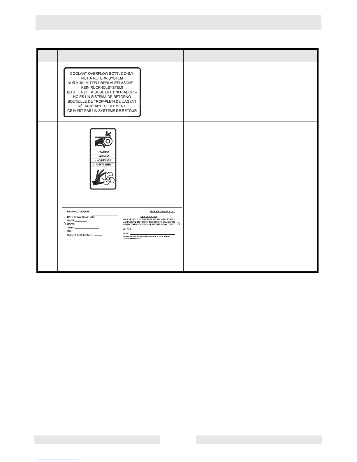
R Coolant overflow bottle only, not a return
system.
S WARNING!
Pinching hazard. Rotating machinery.
Certification Label (VIN Number)
Also attached to each unit is a
Certification Label. This label specifies
that the trailer conforms with all Federal
Motor Vehicle Standards in effect at the
time of manufacture. The label includes
the Vehicle Identification Number (VIN)
for the trailer.
LTC 4 Technical Data
wc_td000157gb.fm 19
2. Technical Data
2.1 Engine
Item Number:
LTC 4L
0009375 Rev.
102 & lower
LTC 4L
0009375 Rev.
103 & above
0620018
LTC 4C
0009376
0620017
0620028
Engine
Make Lombardini Caterpillar
Model LDW903 LDW1003 3003
T ype 3-cylinder , 4-cycle, liquid-cooled diesel
Maximum power rating
kW (Hp)
9.0 (12.1) 10 (13.4) 9.4 (12.6)
Operating power ra ti ng
kW (Hp)
8.1 (10.9) 9.1 (12.2) 8.1 (10.9)
Operating speed
(no-load)
rpm
1850 1850 1850
Alternator
V / A / W
12 / 45 / 540
Battery
V/Ah/CCA
12 / 450
Air cleaner
type
dry-type element
Fuel
type
No. 2 diesel
Fuel tank capacity
l (gal.)
114 (30)
Fuel consumption
l (gal.) / hr.
1.67 (0.44) 1.70 (0.45) 1.70 (0.45)
Running time
hours
68 67 67
Coolant capacity
l (qts.)
4.7 (5.0)
Oil capacity
l (qts.)
2.4 (2.5) 3.5 (3.7)
Oil weight
SAE
15W40 CD or higher
Technical Data LTC 4
wc_td000157gb.fm 20
2.2 Generator
Item Number:
LTC 4L - 60 Hz
0009375
0620018
LTC 4C - 60 Hz
0009376
0620017
0620028
Generator
Frequency
Hz
60 ± 2
Continuous output
kW
6.0
Output
volts/phase
120 / 1Ø
Amps
A
50 / 25
Excitation type Capacitor / Brushless
Power factor 1.0
Voltage regulation - No
load to full load
%
± 5.0
Speed (no-load)
rpm
1850
LTC 4 Technical Data
wc_td000157gb.fm 21
2.3 Machine
LTC 4L LTC 4C
Item Number
0009375 0620018 0009376
0620017
0620028
Machine
Operating wei ght
(GVWR)
kg (lbs.)
815 (1800) 821 (1811) 817 (1802) 832 (1834)
Dimensions
(L x W x H)
cm (in.)
389 x 122
x 160
(153 x 48 x
63)
439 x 162
x 160
(173 x 64 x
63)
389 x 122
x 160
(153 x 48 x
63)
439 x 162
x 160
(173 x 64 x
63)
Height - mast extended
m (ft.)
9 (30)
Lighting system
(1000W)
4
Ballast Coil and core
Max. lighting coverage
@ 0.5 ft. candles
m
2
(acres)
30,400
(7)
Sound level at 7 m
(23 ft.)
dB(A)
71 69 72 71
Tires
size
ST175 / 80D13

Technical Data LTC 4
wc_td000157gb.fm 22
Notes
LTC 4L Operation
wc_tx000543gb.fm 23
3. Operation
3.1 Information Regarding Operation
3.1.1 The information regarding the operation of the machine included in this
manual is condensed. Refer to the Operator’s Manual for complete
operating instructions. Always read, understand, and follow the
procedures in the Operator’s Manual when operating the machine.
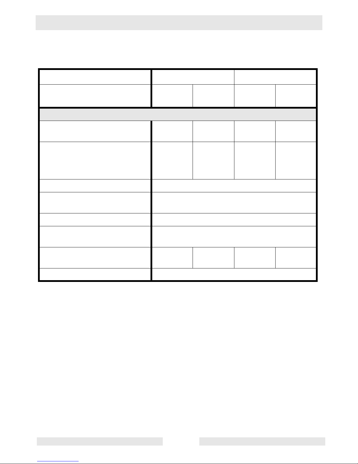
3.2 Locating Trailer
See Graphic : wc_gr0001420
3.2.1 For m ax i mum light coverage locate the Light Tower at ground level or
in a spot higher than the area being lighted.
3.2.2 Posit ion the t railer on a firm, f lat surfac e clear of overhead wires an d
obstructions. Be sure that there is enough area for outrigger
extensions to be fully extended.
3.2.3 Connect the ground stud (l) located on the trailer frame, to a good
earthen ground. Consul t local cod es for prope r grou ndi n g tech ni qu es.
The tower extends up to 9 m (30 ft.). Make sure the area above the
trailer is open and clear of overhead wires and obstructions.
WARNIN
G
Operation LTC 4L
wc_tx000543gb.fm 24
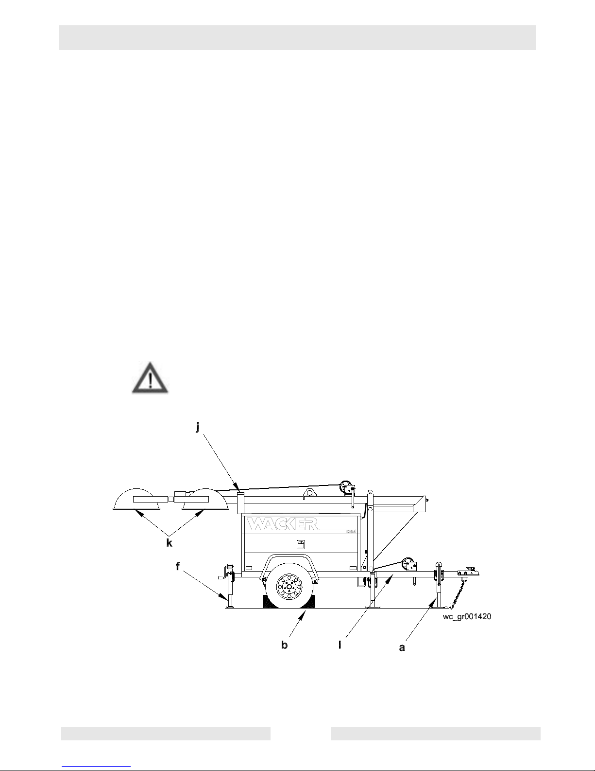
3.3 Leveling Trailer
See Graphic: wc_gr001 42 0, wc_ gr 00 14 23
The trailer must be leveled and t he ou tr i gge r s extended before r a isi n g
the tower. The outriggers must remain extended while the tower is up.
Failure to level the trailer or extend the outriggers will severely reduce
the stability of the unit and could allow the tower to tip and fall.
3.3.1 Pull the locking pin on the tongue jack (a) and rotate the tongue jack
90° as shown. Make sure the tongue jack snaps into position.
Block or chock the trailer wheels (b). Crank the tongue jack down to
raise the trailer tongue off the vehicle.
3.3.2 Pull the outrigger lock pin (c) to release the outrigger. Pull both
outrigger extensio ns (d) out until yo u fe el ou trigge r loc k pin lock ba ck
into place. Rotate jacks (e) down until they snap into position.
3.3.3 Rotate rear jack (f) down, as shown, making sure it snaps into place.
3.3.4 Extend the jack(s) on the highest side(s) of the trailer until they rest
firmly on the ground. Extend the remaining jacks until the trailer is
level.
3.4 Adjusting Lights
See Graphic: wc_gr001 42 3
Each light fixture can be aimed up, down, left or right. Position each
fixture by loose n ing to o lless li ght a dj us ter s (g) and aiming t h e light up
or down. DO NOT loosen the inside nut (x). Loosening this nut could
cause damage to the light fixture. Loosen the nut (h) to turn light
fixtures left o r right. Tighten adjust ers and nuts after posi tioning the
lights.
Always return the light fixtures to aim at the ground when mast is in the
cradle for towing.
WARNIN
G

LTC 4L Operation
wc_tx000543gb.fm 25
3.5 Preparing Trailer for Towing or Lifting
See Graphic: wc_gr001423, wc _gr002166
3.5.1 Check that the mast cr adle lock pi n (j) is in place and secured with the
safety pin.
3.5.2 Ens ur e tha t the t o wer is comp lete ly nes ted ins i de the t ra nsp o rt crad le
and the pin (t) is secure.
3.5.3 Make sure the doors are properly latched.
3.5.4 Return the outriggers to their travel position. Check that the outrigger
bars and jacks are locked in place.
3.5.5 Crank the rear jack (f) all the way in and rotate it 90°.
The the Light Tower is now ready to lift. For towing, continue.
3.5.6 Use the tongue jack (a) to raise the trailer tongue up and then lower it
over hitch on towing vehicle. Lock the hitch to coup l ing and atta ch the
safety chains. Swivel the tongue jack 90° and lock it in place.
3.5.7 Connect the trailer wiring to the towing vehicle. Check the brake, turn,
and tail lights f or proper operation.
3.5.8 Position the light fixtures down (k). For rough, off-road transportation
remove bulbs from fixtures to avoid damage.
3.5.9 Check the tire inflat ion.
3.5.10 Attach a red flag to the end of mast before towing.
CAUTION: Maximum recommended speed for highway towing is 72
km/hour (45 MPH). Recommended off-road towing speed is not to
exceed 16 km/hour (10 MPH) or less depending on terrain.
Operation LTC 4L
wc_tx000543gb.fm 26
3.6 Raising Tower (Manual Winch System)
See Graphic: wc_gr002 16 6
NEVER raise the mast or operate the Light Tower in high winds.
NEVER raise the mast while the engine is running.
HIGH VOLTAGE! DO NOT use the Light Tower if insulation on
electrical cord is cut or worn thro ugh. Repair or re place the cord b efore
using. Bare wires in co ntact wi th the m etal fr ame of the tra iler o r tower
can cause electrocution.
DO NOT position the Light Tower under electrical power lines.
NEVER allow anyone to stand near the r ear of the unit w hile raising th e
mast.
The Light Tower includes two separate winches. One for lifting the
mast to the vertic al position, t he other for raising the tower. Each winch
is an automatic brake-type winch that automatically brakes when the
handle is released. The handle must be rotated to wind in cable as well
as unwind cable.
NEVER touch the winch pawl! Releasing the pawl may cause the
mast or tower to fall.
3.6.1 Check winch cables (n) for wear or damage, and make sure they are
resting properly in pulleys. Do not use the Light Tower if either winch
cable is damaged.
3.6.2 Remove the cradle locking pin (j) from the cradle.
3.6.3 Check the operation of the tongue-mounted winch (o) by rotating the
winch handle 1/4-turn clockwise (“cable in” direction). The winch pawl
must engage winch gear teeth. When operating properly, the winch
pawl will make a “clicking” sound when the winch handle is rotated
clockwise. Do not at tempt to raise the ma st if th e winch is dam aged or
not operating properly.
3.6.4 Continue to rotate the winch handle and raise the mast to the vertical
position until the vertical mast locking pin (p) locks the mast in place.
Be certain the vertical mast locking pin is fully engaged in the locking
position before raising the tower.
WARNING
WARNING
WARNING
WARNING
 Loading...