

WACKER Group CT 36 Series, CT 36ADT, CT 48 Series, CT48AGT-E, CT 48ADT Repair Manual
...
www.wackergroup.com
Walk-Behind
Trowels
CT 30
CT 36
CT 48
REPAIR MANUAL
0112103 001
0600 en
0112103


TROWEL REPAIR FOREWORD
This manual covers machines with Serial Number or Item Number:
0007587, 0007589, 0007590, 0007591, 0007592, 0007594, 0007595, 0007596, 0007597, 0007598, 0007599, 0007601,
0007602, 0007603, 0007697, 0008001, 0008002, 0008003, 0008004, 0008005, 0008006, 0008007, 0008008, 0008011,
0008012, 0008013, 0008014, 0008015, 0008016, 0008019, 0008020, 0008026, 0008027, 0008028, 0008031, 0008032,
0008034, 0008036, 0008040, 0008041, 0008197, 0008198, 0008199, 0008225, 0008226
Operating / Parts Information
You must be familiar with the operation of this machine before you attempt to troubleshoot or make any repairs to it.
Basic operating and maintenance procedures are described in the operator’s / parts manual supplied with the machine.
The operator’s / parts manual should be kept with the machine. Use it to order replacement parts when needed. If this
manual becomes lost, please contact WACKER Corporation to order a replacement.
Damage caused by misuse or neglect of the unit should be brought to the attention of the operator, to prevent similar
occurrences from happening in the future.
This manual provides information and procedures to safely repair and maintain this WACKER model. For your own
safety and protection from injury, carefully read, understand and observe the safety instructions described in this
manual. THE INFORMATION CONTAINED IN THIS MANUAL WAS BASED ON MACHINES IN PRODUCTION AT
THE TIME OF PUBLICATION. WACKER CORPORATION RESERVES THE RIGHT TO CHANGE ANY PORTION
OF THIS INFORMATION WITHOUT NOTICE.
i
FOREWORD
Rev. Serial Number
MENOMONEE FALLS, WI USA 53051
hpkWlbs
dB(A) Manuf. Yr.
Model
kg
MADE
IN USA
Item Number
TROWEL REPAIR
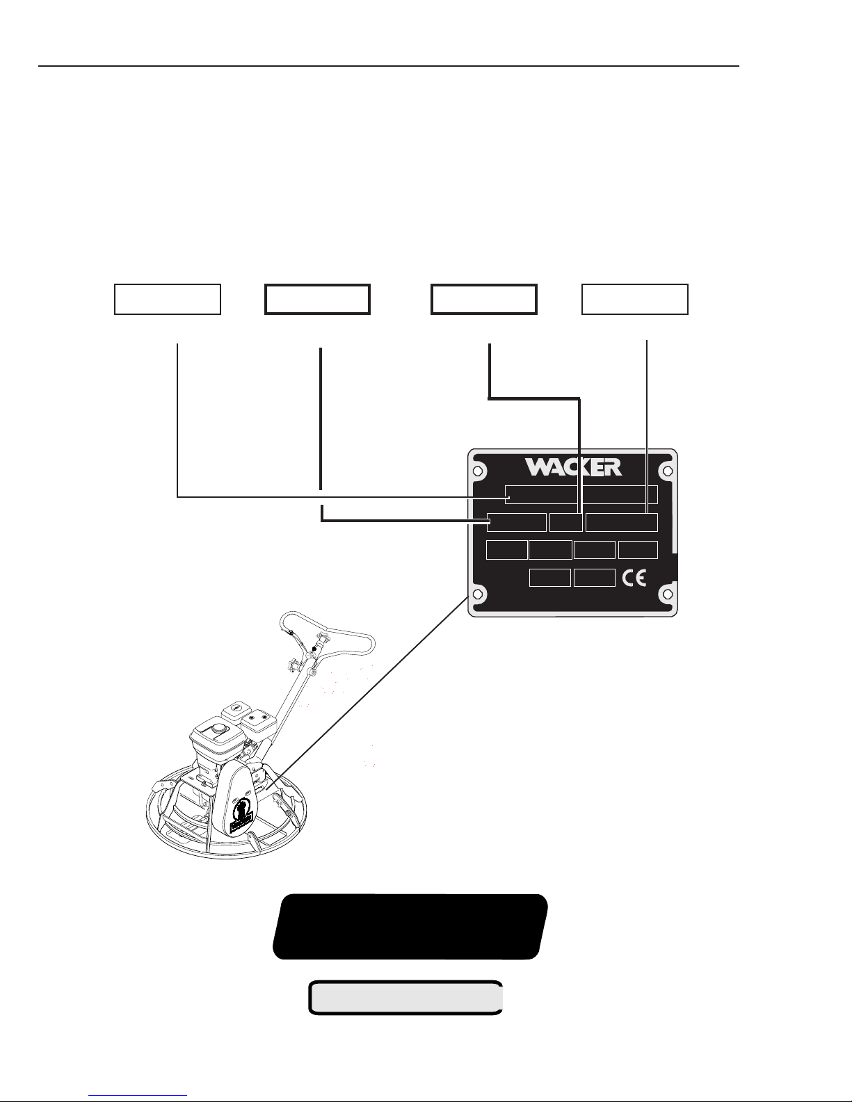
Nameplate
A nameplate listing the Model Number and Serial Number OR the Model Number, Item Number, Revision, and Serial
Number is attached to each unit. Please record the information found on this plate so it will be available should the
nameplate become lost or damaged. When ordering parts or requesting service information, you will always be
asked to specify the model number and serial number OR the model number, item number, revision, and serial
number of the unit.
My machine’s numbers are:
Model number
RevisionItem Number
CT48AGT-ECT48AGT-E
CT48AGT-E
CT48AGT-ECT48AGT-E
00080320008032
0008032 101101
00080320008032
101101
101
Serial Number
0001010100010101
00010101
0001010100010101
88223
Pro-Shift
1022SD42
PATENT PENDING
ii
®
111545

Trowel
Repair Manual
Table of Contents
1 Introduction
1.1 Safety Notes ................................................................................................ 1-2
1.2 Laws Pertaining to Spark Arresters .............................................................. 1-2
1.3 Operating Safety .......................................................................................... 1-3
1.4 Engine Safety...............................................................................................1-3
1.5 Service Safety ............................................................................................. 1-4
1.6 Technical Data ............................................................................................. 1-5
1.7 Application ................................................................................................... 1-6
1.8 General Description ...................................................................................... 1-6
1.9 Periodic Maintenance Schedule ................................................................... 1-6
1.10 Symbols ....................................................................................................... 1-6
2 Guide Handle
2.1 Throttle Control Lever Adjustment ................................................................ 2-1
2.2 Throttle Cable Replacement ......................................................................... 2-1
2.3 Upper Handle - Twist Pitch Control - Exploded View .....................................2-2
2.4 Twist Pitch Control Cable Replacement ........................................................2-4
2.5 Upper Handle -
2.6
Pro-Shift
Pro-Shift
®
Pitch Control Cable Replacement ................................................. 2-8
®
- Exploded View ................................................... 2-6
3 Clutch
3.1 Belt Replacement ......................................................................................... 3-1
3.2 Belt Drive - Exploded View ........................................................................... 3-2
3.3 Clutch Replacement ..................................................................................... 3-3
3.4 Clutch - Exploded View ................................................................................3-4
3.5 Clutch Overhaul ............................................................................................ 3-5
4 Spider
4.1 Trowel Assembly - Exploded View ............................................................... 4-1
4.2 Spider........................................................................................................... 4-2
5 Drivetrain
5.1 Engine Removal - Exploded View ................................................................. 5-1
5.2 Engine ..........................................................................................................5-2
5.3 Gearcase Removal - Exploded View............................................................. 5-3
5.4 Gearcase ..................................................................................................... 5-4
5.5 Gearbox - Exploded View ............................................................................. 5-6
5.6 Gearcase Overhaul ...................................................................................... 5-7
Troubleshooting
1-1

1 INTRODUCTION TROWEL REPAIR
1.1 Safety Notes
This manual contains NOTES, CAUTIONS, and WARNINGS which must be followed to reduce the possibility of
improper service, damage to the equipment, or personal injury. Read and follow all NOTES, CAUTIONS and WARNINGS
included in instructions.
Contains additional
Note:
information important to a procedure.
CAUTION: Provides information important to prevent
errors which could damage machine or components.
WARNING
Warns of conditions or practices which
could lead to personal injury or death!
1.2 Laws Pertaining to Spark Arresters
Notice: Some states require that in certain locations, spark arresters be used on internal combustion engines. A spark
arrester is a device designed to prevent the discharge of sparks or flames from the engine exhaust. It is often required
when operating equipment on forested land to reduce the risk of fires. Consult the engine distributor or local authorities
and make sure you comply with regulations regarding spark arresters.
1-2

TROWEL REPAIR INTRODUCTION 1
1.3 Operating Safety
Familiarity and proper training are required for the safe operation of this equipment! Equipment operated improperly or
by untrained personnel can be dangerous! Read the operating instructions contained in both the operator's manual and
the engine manual and familiarize yourself with the location and proper use of all controls.
WARNING
NEVER allow anyone to operate this equipment
without proper training. People operating this equipment must be familiar with the risks and hazards
associated with it.
NEVER touch engine or muffler while the engine is
on or immediately after it has been turned off. These
areas get hot and may cause burns.
NEVER use accessories or attachments which are
not recommended by WACKER. Damage to equipment and injury to the user may result.
NEVER operate machine with the belt guard missing. Exposed drive belt and pulleys create potentially dangerous hazards that can cause serious
injuries.
NEVER leave machine running unattended.
ALWAYS be sure operator is familiar with proper
safety precautions and operation techniques before using machine.
ALWAYS wear protective clothing when operating
equipment. For instance, goggles or safety glasses
will protect eyes from damage caused by flying
debris.
ALWAYS close fuel valve on engines equipped
with one when machine is not being operated.
ALWAYS store equipment properly when it is not
being used. Equipment should be stored in a
clean, dry location out of the reach of children.
ALWAYS operate machine with all safety devices
and guards in place and in working order.
1.4 Engine Safety
Internal combustion engines present special hazards during operation and fueling! Read and follow warning instructions
in engine owner's manual and safety guidelines below. Failure to follow warnings and safety guidelines could result in
severe injury or death.
WARNING
DO NOT smoke while operating machine.
DO NOT smoke when refueling engine.
DO NOT refuel hot or running engine.
DO NOT refuel engine near open flame.
DO NOT spill fuel when refueling engine.
DO NOT run engine near open flames.
DO NOT run machine indoors or in an enclosed
area such as a deep trench unless adequate
ventilation, through such items as exhaust fans or
hoses, is provided. Exhaust gas from the engine
contains poisonous carbon monoxide gas; exposure to carbon monoxide can cause loss of consciousness and may lead to death.
ALWAYS refill fuel tank in well-ventilated area.
ALWAYS replace fuel tank cap after refueling.
1-3

1 INTRODUCTION TROWEL REPAIR
1.5 Service Safety
Poorly maintained equipment can become a safety hazard! In order for the equipment to operate safely and properly over
a long period of time, periodic maintenance and occasional repairs are necessary.
WARNING
DO NOT attempt to clean or service machine
while it is running. Rotating parts can cause
severe injury.
DO NOT crank a flooded engine with the spark
plug removed on gasoline-powered engines. Fuel
trapped in the cylinder will squirt out the spark plug
opening.
DO NOT test for spark on gasoline-powered engines, if engine is flooded or the smell of gasoline
is present. A stray spark could ignite fumes.
DO NOT use gasoline or other types of fuels or
flammable solvents to clean parts, especially in
enclosed areas. Fumes from fuels and solvents
can become explosive.
ALWAYS keep area around muffler free of debris
such as leaves, paper, cartons, etc. A hot muffler
could ignite them, starting a fire.
ALWAYS replace worn or damaged components
with spare parts designed and recommended by
WACKER.
ALWAYS disconnect spark plug on machines
equipped with gasoline engines, before servicing, to
avoid accidental start-up.
ALWAYS keep machine clean and labels legible.
Replace all missing and hard-to-read labels. Labels
provide important operating instructions and warn of
dangers and hazards.
1-4

TROWEL REPAIR INTRODUCTION 1
1.6 Technical Data
Trowel
Trowel Diameter in. (mm)
Number of Blades
Gearbox Lubrication type
oz. (ml)
Speed Range rpm
Pitch Range degrees°
CT 36ADT/ CT 48ADT/
CT 30ADT CT 30AGT CT36ADP CT 36AGT CT 48ADP CT 48AGT
30 (762) 30 (762) 36 (914) 36 (914) 48 (1220) 48 (1220)
4
Mobil SHC634
Approx. 45 (1330)
60–100 125–165 60–100 125–165 60–100 125–165
0–15
1-5

1 INTRODUCTION TROWEL REPAIR
1.7 Application
The CT series of trowels are modern, high production
machines intended for floating and finishing freshly poured
concrete slabs. The machine’s good balance, adjustable
handle, and easily accessible controls add to operator
comfort and productivity. An automatic stop switch, or a
combination of an automatic stop switch and an operator
present lever, provide added operator safety. Finishing
rates will depend on operator skill and job conditions.
1.8 General Description
For the CT product line of trowels, engine power is
transferred through a centrifugal clutch and V-belt to the
gearcase and down to the trowel blades. The four trowel
blades are mounted on a spider assembly mounted on the
gearcase output shaft. The spider assembly adjusts the
trowel angle by being raised by the yoke-trowel blade lift.
The trowels can be tilted from 0° - 15 °. The speed
of the trowels ranges from 60-165 rpm, depending on
the model.
1.9 Periodic Maintenance Schedule
The chart below lists basic trowel maintenance. Refer to engine manufacturer’s Operator’s Manual for information on
engine maintenance. A copy of the engine Operator’s Manual was supplied with the machine when it was shipped.
Daily After After Every two Every Every two
before each first weeks or month or years or
starting use 5 hours 50 hrs. 100 hrs. 750 hrs.
Check and tighten external hardware. ●
Grease trowel arms. ●
Check and adjust drive belt. ●●
Grease adjusting yoke. ●
Change gearcase oil. ●
Inspect pitch cable. ●
Change trowel gearcase lubricant. ●
1.10 Symbols
Symbols Used on Repair Pages
L1 Indicates a sealant or threadlocking compound to
be used when assembling part.
[L1] Refer to Sealant Chart at end of manual for
description of sealants.
T1 Indicates the correct torque value for
assembling part.
[T1] Refer to Torque Chart at end of manual for
standard torque measurements.
1-6
TROWEL REPAIR GUIDE HANDLE 2
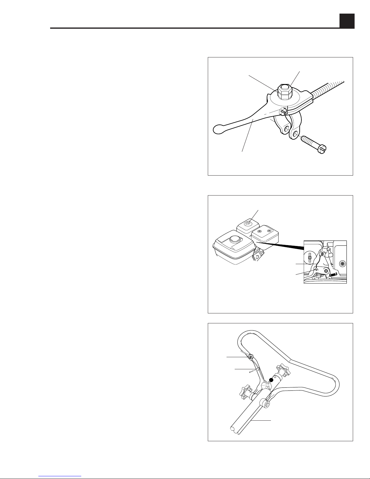
2.1 Throttle Control Lever Adjustment
The throttle control is used to vary the speed of the engine
and to control the rpm of the trowel blades to meet
specific applications and job conditions.
The throttle control uses ratchet action to select and hold
the desired throttle position. If the throttle fails to hold its
selected position, check lever pressure adjustment and
ratchet action.
Adjustment:
1. Tighten hex nut (a) on top of throttle control lever (c)
to increase pressure on throttle control.
2. Lock adjustment in place by tightening jam nut (b).
2.2 Throttle Cable Replacement
Machines are available with various styles of throttle
control. The replacement of this cable is basically the
same for all models.
Disassembly:
a
b
c
1001RM17
d
1. Remove M6 wing nut (d), filter cover, second M6 wing
nut, and filter.
2. Disconnect throttle cable (e) from throttle lever (f).
3. Pull throttle through cable raceway.
4. Disconnect cable clamp (h) from handle. Disconnect
throttle control lever (g) from handle.
5. Disconnect cable (e) from throttle control lever (g).
Assembly:
1. Reconnect cable (e) to throttle control lever (g).
2. Connect throttle control lever to handle.
3. Push throttle cable through cable raceway (j).
4. Connect throttle cable (e) to throttle lever (f).
5. Install cable clamp (h) to take up excess throttle cable.
e
f
1001RM01
g
h
6. Adjust throttle cable so that engine is in idle when throttle
control lever is in the idle position. Tighten cable.
7. Reinstall air filter, wing nut, filter cover and second
wing nut (d).
j
1001RM02
2-1
2 GUIDE HANDLE TROWEL REPAIR
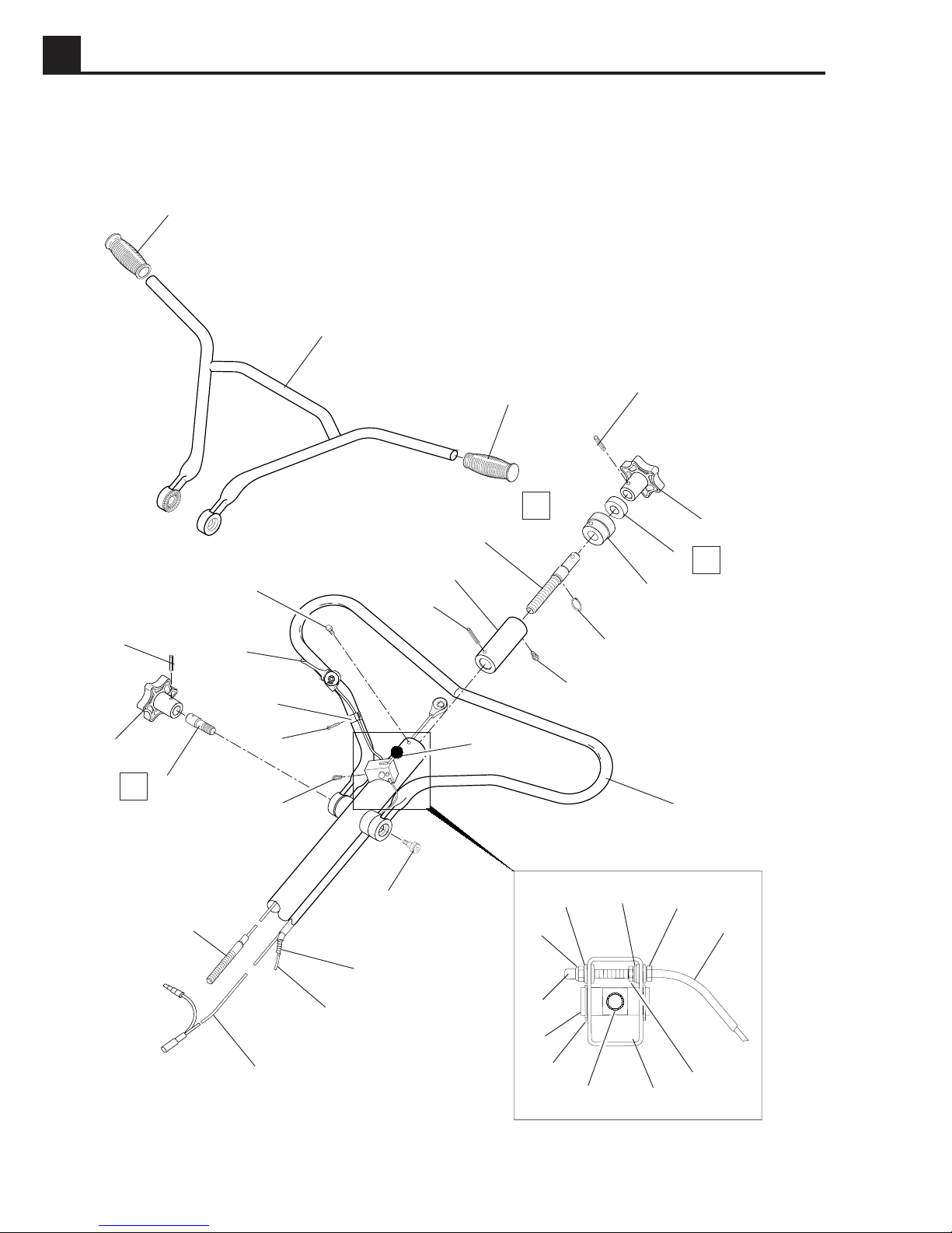
2.3 Upper Handle - Twist Pitch Control - Exploded View
1
2
1
N2
9
12
3
4
23
N2
13
14
15
16
10
11
8
17
3
4
5
N1
6
7
34
22
21
2-2
20
19
18
25
24
33
32
26
31
27
28
21
29
30
1013SD79

TROWEL REPAIR GUIDE HANDLE 2
Ref. Description Qty.
1 Handle-grip 2
2 Handle-bicycle 1
3 Pin-roll style (incl. 1) 2
4 Knob-pitch control 2
5 Bearing-ball 1
6 Holder-handle bearing 1
7 Retaining ring-ext. 1
8 Screw M6x16 1
9 Shaft-pitch control 1
10 Nut 3/4-6 1
11 Pin-roll 1
12 Screw M6x10 1
13 Lever-throttle control 1
14 Clamp 1
15 Screw M5x25 1
16 Screw #8-32x1/4 2
17 Knob 1
Ref. Description Qty.
18 Screw 3/8-16x1-3/8 1
19 Casing-cable 1
20 Cable-throttle 1
21 Wiring harness 1
22 Cable-control, blade 1
23 Rod-handle adjustment 1
24 Cap-screw head 1
25 Nut-lock M5 1
26 Grommet 2
27 Washer B5.3 1
28 Screw M5x45 1
29 Nut BM5 1
30 Cover-switch box 1
31 Handle-switch 1
32 Retaining ring-ext. 1
33 Shaft-handle pivot 1
34 Handle-adjustable 1
N2 - Lubricate threads before assembly.N1 - Fill bearing with grease before assembly.
2-3
2 GUIDE HANDLE TROWEL REPAIR
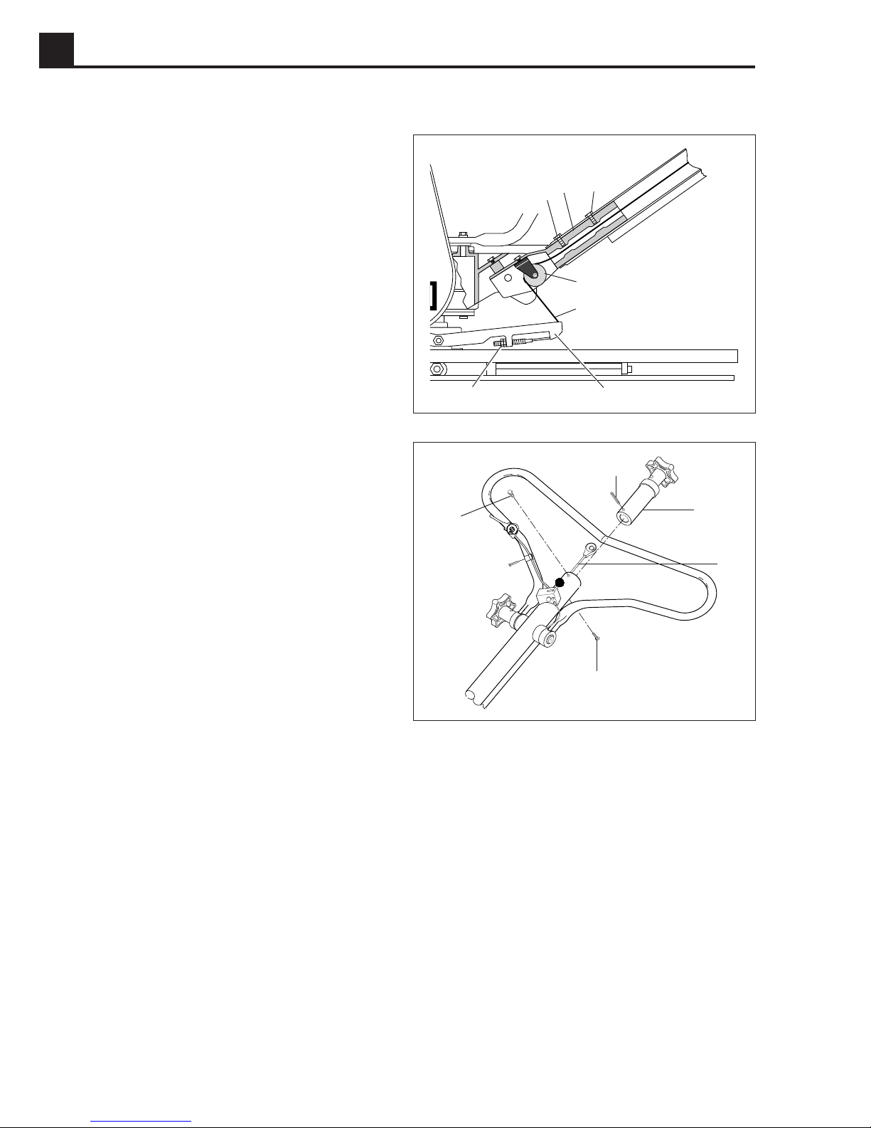
2.4 Twist Pitch Control Cable Replacement
Disassembly:
1. Remove two retaining nuts (f) from the pitch control
cable (d).
2. Disengage cable from fork (e) and slide through
(c).
pulley
3. Remove two M8 screws
base (b). Carefully pull handle and control cable away
from handle base.
4. Remove M6 screw (g) from handle. Remove
M6 screw (m) from underside of handle.
5. Pull Twist Control assembly (j) and pitch control cable
(k) from handle.
6. Drive roll pin (h) from Twist Control assembly.
Remove cable.
(a) holding handle to handle
g
a
b
a
c
d
f
e
1013SD53
h
j
k
2-4
m
1001RM03
 Loading...