


www.wackergroup.com
Operator's manual
Internal vibrator frequency converter
IRFUN
0203511en 003
01.2007


3
Foreword
1. Foreword
For your own safety and protection from bodily injuries, carefully read,
understand and follow the safety information in this manual.
Please operate and maintain your Wacker machine in accordance with
the instructions in this operator's manual. Your Wacker machine will reward you with troublefree operation and a high degree of availability.
Defective components must be replaced immediately.
All rights, especially the right for copying and distribution, are reserved
Copyright 2007 by Wacker Construction Equipment AG
No part of this publication may be reproduced in any form or by any
means, electronic or mechanical, including photocopying, without express permission in writing from Wacker Construction Equipment AG.
Any type of reproduction, distribution or saving on data carriers of any
type or method not authorized by Wacker represents an infringement of
valid copyrights and will be prosecuted. We expressly reserve the right
to make technical modifications - even without special notice - which aim
at further improving our machines or their safety standards.

Table of contents
4
1. Foreword 3
2. Safety information 5
2.1 General instructions ..............................................................................5
2.2 Operation ...............................................................................................5
2.3 Safety checks ........................................................................................6
2.4 Maintenance ..........................................................................................7
2.5 Transport ...............................................................................................8
2.6 Maintenance checks ..............................................................................8
3. Technical data 9
4. Description 17
4.1 Application ...........................................................................................17
4.2 Functional description .........................................................................17
5. Operation 18
5.1 Starting up ...........................................................................................18
5.2 Connection using separate extension cable ........................................19
5.3 Switching off the machine ...................................................................20
6. Description/maintenance 21
6.1 Protection against overheating ............................................................21
6.2 Maintenance schedule ........................................................................21
6.3 Disassembly and assembly .................................................................21
6.4 Maintenance ........................................................................................22
7. Repair instructions 23
7.1 Repair instructions, faults ....................................................................23
8. Wear dimensions 26
9. Disposal 27
9.1 Environmentally friendly recycling .......................................................27
EC Declaration of Conformity 29
DIN EN ISO 9001 Certificate 31

SV00043en.fm 5
Internal vibrators Safety information
2. Safety information
for internal vibrators with integrated frequency converter
2.1 General instructions
2.1.1 The IRFUN may only be worked on independently by persons who
∗ are at least 18 years of age,
∗ are physically and mentally fit for this job,
∗ have been instructed in operating IRFUN and have proved their ability
for the job to the employer and
∗ may be expected to carry out the job they are charged with carefully.
They must have been assigned to work on the IRFUN by the employer.
2.1.2 IRFUN is to be applied only for compacting work. Both the manufactur-
er's operator's manual and this safety information must be observed.
The machine must be immersed in the mass to be compressed.
2.1.3 The persons charged with the operation of IRFUN must be made fa-
miliar with the necessary safety measures relating to the machine. In
case of extraordinary uses, the employer shall give the necessary additional instructions.
2.1.4 Observe the accident prevention regulations set forth by the profes-
sional association for electrical equipment and material and use them
as a basis during all work performed with this machine.
2.2 Operation
2.2.1 Make sure that IRFUN with electric motor drive is only attached to the
voltage and frequency indicated on the nameplate. The nameplate is
located on the inside of the switch box cover. The voltage to which the
machine must be connected is also embossed on the switch housing.
Choose correct cross section for extension cord.
2.2.2 IRFUN may only be connected to electric power supplies with a fault
current protective switch.
Either fault current protective switches of universal sensitivity must be
used or it must be ensured that the IRFUN is connected on its own
without any other consumers to an fault current protective switch designed for non-sinusoidal current consumption.
When connecting the IRFUN to public mains networks, sockets with
15 A fuse must be used.

Safety information Internal vibrators
SV00043en.fm 6
2.2.3 The machine corresponds to class rating 1 (grounded conductor).
2.2.4 Prior to starting IRFUN, make sure that the components are screwed
on securely.
2.2.5 Do not insert or pull out the power plug as a means of turning IRFUN
on or off.
2.2.6 The power cable of IRFUN must not be used to pull out the plug from
the plug receptacle.
2.2.7 Protect electric cable from heat, oil, and sharp edges.
2.2.8 Electrical equipment and material may only be used if they comply with
operational and local safety requirements. They must be in proper condition and this condition is to be maintained.
2.2.9 Activated IRFUNs should not come into contact with any solid objects
over a long period of time, long running times in the air must be avoided.
2.2.10 When taking a break or when leaving IRFUN, the operator must switch
off the machine and park it securely in such a way to ensure that it cannot tip over or fall down.
2.2.11 Do not operate IRFUN in areas where explosions may occur.
2.2.12 Appropriate protective gloves must always be worn when handling
IRFUN. Do not touch the hot vibrator head.
2.2.13 The protective hose must be used to guide the machine during opera-
tion. Using the vibrator head to guide the IRFUN can cause vascular
diseases.
2.2.14 The transmission of vibration oscillations to the material to be com-
pacted can damage or destroy the casing. Casings must be secured
according to regulations before using the machine.
2.3 Safety checks
2.3.1 Before starting operation, the operator has to check that all control and
safety devices are functioning properly.
2.3.2 Prior to connecting the machine, check the electric cable and socket
for damage on a regular basis.

SV00043en.fm 7
Internal vibrators Safety information
2.3.3 Also check the proper functioning of the On/Off switch and the fault
current protective switch.
2.3.4 If defects on the safety devices or other defects impairing the opera-
tional safety of internal vibrators are observed, the supervisor must be
informed immediately. The machine must not be commissioned.
2.3.5 If there are defects jeopardizing operational safety, the machine has to
be switched off immediately.
2.3.6 Check the bottom part of the pipe for cracks, damage or loose screw
connections. The vibration cylinders are not suitable for use if the bottom part of the pipe is missing.
2.3.7 Check the clamps on the connections.
2.3.8 The machine can start to run immediately as soon as it is connected to
the mains depending on the switch setting. This is also possible if the
switch is defective.
2.4 Maintenance
2.4.1 IRFUN must only be opened and repaired by qualified and authorized
personnel.
2.4.2 Only use original spare parts. Alterations to this machine, incl. adjust-
ments of the maximum engine speed set by the manufacturer may only
be carried out with the express permission of WACKER. In case of
non-observance, all liability shall be refused.
2.4.3 Disconnect IRFUN from the electrical power supply system by pulling
out the mains plug before carrying out maintenance and repair work.
2.4.4 Work on the electric parts of the machine may only be carried out by
skilled technicians.
2.4.5 The green-yellow grounded conductor must be longer than the current-
carrying conductors, so that it does not tear off first should the strain
relief fail. If interrupted, it can cause fatal injury. After conducting repairs, check the grounded conductor for continuity.
2.4.6 As soon as maintenance and repair jobs have been completed, all
safety devices must be properly reinstalled. Screws must be tightened
according to the tightening torques specified in the standards.
2.4.7 Clean IRFUN daily. Make sure not to damage the lines when using
high pressure washers.

Safety information Internal vibrators
SV00043en.fm 8
2.5 Transport
2.5.1 Secure IRFUN against falling down during transportation.
2.6 Maintenance checks
2.6.1 According to the conditions and frequency of use, IRFUN must be
checked for safe operation by a technician, for example at a WACKER
service station, at least once every 6 months and repaired if necessary.
Please observe the appropriate rules and regulations valid in your country.
TD00701en.fm 9
Technical data
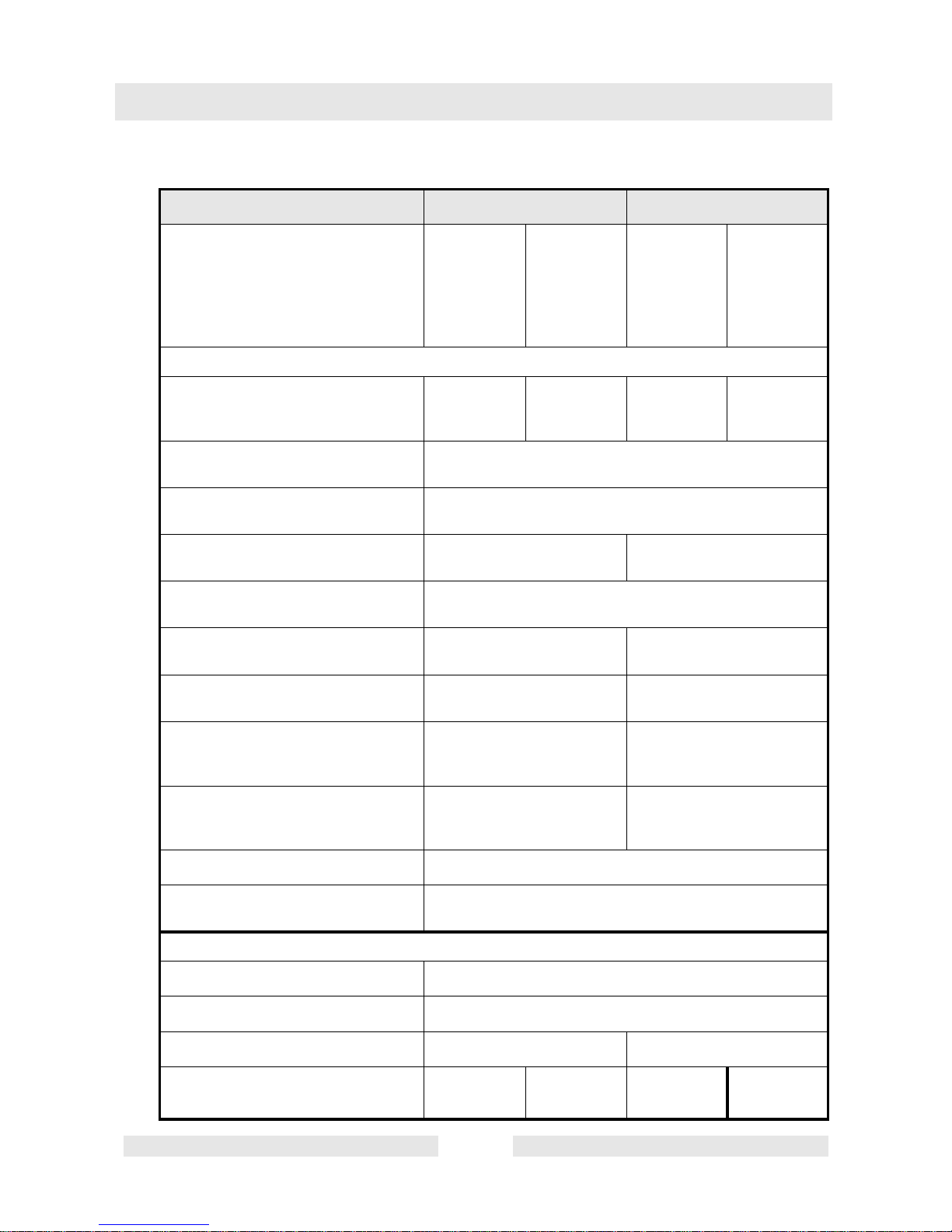
3. Technical data
IRFUN 38/115 IRFUN 45/115
Item no.
8 m
8 m GV
10 m
10 m GV
0008494
0008631
0008495
0008722
0008769
0008771
0008770
0008772
0008496
0008630
0008497
0008723
0008773
0008775
0008774
0008776
Vibrator head
Integrated three-phase
AC motor
kW:
0.41 0.47 0.58 0.68
Voltage
V:
214 3~
Frequency
Hz:
200
Rated current
A:
1.6 2.3
Vibrations
rpm:
12000
Vibrator diameter
mm (in):
38 (1.5) 45 (1.8)
Vibrator length
mm (in):
345 (13.6) 382 (15)
Vibrator weight (mass)
(without hose connection)
kg (lb):
2.2 (4.85) 3.5 (7.72)
Effective diameter in concrete
cm (ft):
up to:
50 (1.6) 60 (2.0)
Oil type
SAE 0W-30
Oil quantity
cm
3
(in3):
8 (0.49)
Inverter / mains connection value
Alternating current V:
110 - 130 1~
Frequency Hz:
50 / 60
Current A:
68
Power kVA:
kW:
0.72
0.85
0.69
0.55
0.96
0.74
0.92
0.74

Technical data
TD00701en.fm 10
Sound pressure level LpA
at operator's station
dB(A):
79
The weighted effective acceleration
value, determined according to
EN ISO 5349
m/s
2
:
2.5
These noise and vibration figures were calculated with the internal vibrator being freely suspended in
air at the nominal speed of the drive motor.
IRFUN 38/115 IRFUN 45/115
TD00701en.fm 11
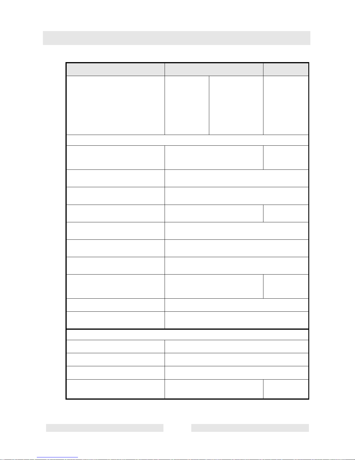
Technical data
IRFUN 57/115 IRFUN 57k/115
Item no.
8 m
8 m GV
10 m
10 m GV
0008481
0008482
0008628
0008724
0008928, 0008777
0008779
0008778
0008780
0008629
Vibrator head
Integrated three-phase
AC motor
kW:
1.04 0.76
Voltage
V:
214 3~
Frequency
Hz:
200
Rated current
A:
3.5 2.6
Vibrations
rpm:
12000
Vibrator diameter
mm (in):
58 (2.3)
Vibrator length
mm (in):
400 (15.7)
Vibrator weight (mass)
(without hose connection)
kg (lb):
5.8 (12.79) 4.8 (10.59)
Oil type
SAE 0W-30
Oil quantity
cm
3
(in3):
12 (0.73)
Inverter / mains connection value
Alternating current V:
110 - 130 1~
Frequency Hz:
50 / 60
Current A:
12
Power kVA:
kW:
1.38
1.1
1.38
0.92

Technical data
TD00701en.fm 12
Sound pressure level LpA
at operator's station
dB(A):
79
The weighted effective acceleration
value, determined according to
EN ISO 5349
m/s
2
:
2.5 4
These noise and vibration figures were calculated with the internal vibrator being freely suspended
in air at the nominal speed of the drive motor.
IRFUN 57/115 IRFUN 57k/115

TD00701en.fm 13
Technical data
IRFUN 38/230 IRFUN 45/230
Item no.
7 m
8 m
0007956
0008611
0008635
0008640
0007957
0008612
0610109
0610110
0008634
0008639
Vibrator head
Integrated three-phase
AC motor
kW:
0.475 0.682
Voltage
V:
214 3~
Frequency
Hz:
200
Rated current
A:
1.6 2.3
Vibrations
rpm:
12000
Vibrator diameter
mm (in):
38 (1.5) 45 (1.8)
Vibrator length
mm (in):
345 (13.6) 382 (15)
Vibrator weight (mass)
(without hose connection)
kg (lb):
2.2 (4.85) 3.5 (7.72)
Effective diameter in concrete
cm (ft):
up to:
50 (1.6) 60 (2.0)
Oil type
SAE 0W-30
Oil quantity
cm
3
(in3):
8 (0.49)
Inverter / mains connection value
Alternating current V:
220 - 240 1~
Frequency Hz:
50 / 60
Current A:
34
Power kVA:
kW:
0,69
0,55
0,92
0,74

Technical data
TD00701en.fm 14
Sound pressure level LpA
at operator's station
dB(A):
79
The weighted effective acceleration
value, determined according to
EN ISO 5349
m/s
2
:
2.5
These noise and vibration figures were calculated with the internal vibrator being freely suspended in air at the nominal speed of the drive motor.
IRFUN 38/230 IRFUN 45/230

TD00701en.fm 15
Technical data
IRFUN 57/230 IRFUN 57k/230
Item no.
7 m
8 m
0007958
0008613
0610107
0610108
0008632
0008637
0008464
0008636
0008633
0008638
Vibrator head
Integrated three-phase
AC motor
kW:
1.04 0.76
Voltage
V:
214 3~
Frequency
Hz:
200
Rated current
A:
3.5 2.6
Vibrations
rpm:
12000
Vibrator diameter
mm (in):
58 (2.2)
Vibrator length
mm (in):
400 (15.7) 330 (13)
Vibrator weight (mass)
(without hose connection)
kg (lb):
5.8 (12.79) 4.8 (10.59)
Effective diameter in concrete
cm (ft):
up to:
85 (2.8) 65 (2.1)
Oil type
SAE 0W-30
Oil quantity
cm
3
(in3):
12 (0.73)
Inverter / mains connection value
Alternating current V:
220 - 240 1~
Frequency Hz:
50 / 60
Current A:
65
Power kVA:
kW:
1.38
1.1
1.15
0.92

Technical data
TD00701en.fm 16
Sound pressure level LpA
at operator's station
dB(A):
79
The weighted effective acceleration
value, determined according to
EN ISO 5349
m/s
2
:
4
These noise and vibration figures were calculated with the internal vibrator being freely suspended in
air at the nominal speed of the drive motor.
IRFUN 57/230 IRFUN 57k/230

T01036en.fm 17
Description
4. Description
4.1 Application
The machine is run with single phase current, and is a combination of
an internal vibrator and a frequency converter.
4.2 Functional description
The converter in the inverter rectifies the input voltage.
The direct voltage is converted in the d.c.-a.c. converter into 3-phase
alternating current (rotary current) and the frequency increased from
50/60 Hz to 200 Hz.
The d.c.-a.c. converter works in "pulse width modulation" mode which
generates a sinusoidal output current as an average, which ensures
the error-free operation of the connected machines.
The soft start of the connected machines permits the full utilization of
the output capacity of the inverter.
The actuation of the rectifier and inverter is carried out by a control
electronics with microprocessor.
Rectifier 100/115/
230/240V
D.c.-a.c. converter
Electronics
Pulse width modulation
Sinusoidal average
50/60 Hz 200 Hz

Operation
T01036en.fm 18
5. Operation
5.1 Starting up
Connection:
The machine is set to its nominal voltage at factory. Connection to
1-phase-alternating current 50 or 60 Hz.
Assembly instructions for the version without plug receptacle
Danger of electrocution!
Only a qualified electrician is permitted to assemble the plug and per-
form a safety check according to the directives in effect.
Observe the assembly instructions!
Switching on:
Switching on the machine means that the voltage and frequency of the
machine are powered up until the nominal value (soft start) preventing
the generation of critical switch-on current strengths.
The machine is suited for the connection to power generation units if
their operating voltage is between 230/115 V + 15 % for every load
type and the manufacturer of the unit permits operation of consumers
with capacitors. If the machine is operated with power generator units,
a synchronous unit should be selected as far as possible.
Danger to life

T01036en.fm 19
Operation
5.2 Connection using separate extension cable
The cross section required depends on the length of the extension cable:
Type Length L m
Section mm
2
38/115 < 16 1,5
<
27 2,5
<
43 4
<
65 6
38/230 <
66 1,5
<
110 2,5
<
176 4
45/115 <
12 1,5
<
20 2,5
<
32 4
<
49 6
45/230 <
50 1,5
<
83 2,5
<
132 4
57/115 <
13 2,5
<
21 4
<
32 6
<
53 10
57/230 <
33 1,5
<
55 2,5
<
88 4
57k/230 <
40 1,5
<
66 2,5
<
105 4

Operation
T01036en.fm 20
5.3 Switching off the machine
First switch off the machine. Then pull the mains plug from the socket.

T01036en.fm 21
Description/maintenance
6. Description/maintenance
6.1 Protection against overheating
This machine is protected against overheating by means of a thermal
circuit breaker. Every phase is equipped with a separate thermal circuit
breaker.
If the thermal circuit breaker is activated, switch off the machine and
allow it to cool down.
6.2 Maintenance schedule
6.3 Disassembly and assembly
The vibrator head must only be clamped in the lower area of the thick
cap.
Component Maintenance work Maintenance interval
Feed line
Visual check - cables and switch
box membrane.
Daily
a
Bottle sizes a
38 100
45 120
57 105
57k 80
65 130
65k 105

Description/maintenance
T01036en.fm 22
6.4 Maintenance
6.4.1 When the wear dimension has been reached the corresponding parts
must be replaced. Seal the housing components at the connection with
ergo 4205 and protect against removal by spot welding.
∗ for IR... 30:
Completely replace the vibrator head.
∗ for IR... 38/45/57:
Connecting lines between hose connection and vibrator head:
The closure of the spade connector (1) must be ensured using the
shrink-on tubing (2). See illustration.
∗ for IR... 65:
Connect connecting cables by crimping them to both sides of the butt
connectors.
6.4.2 After opening the vibrator head the correct oil level must be ensured
prior to assembly (see technical data).

T01036en.fm 23
Repair instructions
7. Repair instructions
Work on the electric parts of the machine may only be carried out by
skilled technicians.
7.1 Repair instructions, faults
The machine must not be opened until approx. 5 minutes after pulling
the plug from the socket to allow the integrated capacitors to discharge.
Have maintenance carried out by trained personnel.
Possible errors:
As long as the green LED is lit, the circuit board is electrically charged
- even after you switch off the line voltage. The green LED goes out
when the condensers are discharged.
The diagnostic lamps built into the inverter, five red LEDs and a green
LED, help you troubleshoot any problems you may encounter.
However, this requires, that you open the inverter housing and apply
voltage. This must be carried out by a specialist or a properly
instructed employee.
Interruption of the cable connection
inverter/vibrating cylinder
Insulation fault of the inverter, the
motor cable or the vibrator head
Inverter is overloaded
The output stage of the inverter is
overloaded due to a short-circuit,
ground fault or error in the vibrating
cylinder
Line input voltage too high / too low
Operating control lamp

Repair instructions
T01036en.fm 24
There is a risk of injury should a condenser explode when voltage is
applied and, as a result thereof, potting compound is ejected. This is
why you should always wear eye protection and avoid the area right
above the condensers.
Before you apply voltage, always carry out a visual inspection of the
opened inverter. Condensers with bulged tops or ones that are higher
than the others are already damaged. You must not apply voltage to
this inverter!
If a red LED lights up when you turn on the machine, the machine has
shut down because of a detected error.
(*) - see Technical Data
For additional protection of the machine against excessive input voltage a metal-oxide varistor has been installed in the input circuit.
Malfunction Cause Remedy
Green LED is not lit.
Internal vibrator (IR)
not running.
- Supply cable
interruption.
- Poor contact
transitions.
- Check supply cable.
- Check contact transitions
(switches, connectors) and
rework if necessary.
Green and first red
LEDs illuminate.
IR not running.
- Cable disruption
between frequency
converter (FU) and IR.
- Fault in the FU
electronics.
- Check cables and replace if
faulty.
- Replace FU.
Green and second
red LEDs illuminate.
IR not running.
- Ground contact in the
FU or IR.
- Insulation measurements
at IR and FU, replace faulty
components.
Green and third red
LEDs illuminate.
IR not running.
- Temperature in the FU
housing too high.
- IR runs sluggish.
- Measure the current values
(*) in the output lines.
- Remove fault in the IR.
Green and fourth
red LEDs illuminate.
IR not running.
- Short circuit between
FU and IR.
- Locate the short circuit by
measurements and
remove.
Green and fifth red
LEDs illuminate.
IR not running.
- Incorrect input voltage,
too high or too low.
- Measure voltage at the
switch.
- Check generator.

T01036en.fm 25
Repair instructions
This looks very similar to a small plate capacitor in its design. It is
characterized by a characteristic similar to a Z diode and a very high
load capacity. Its resistance of more than 1 MΩ collapses during
overvoltage in less than 50 nano seconds to less than 1 Ω in extreme
cases.
This protects the electronics against excessive input voltage.
The output frequency is adjusted to 200 Hz using the potentiometer.
Secure the adjustment screw of the potentiometer with locking paint.

Wear dimensions
SK00630en.fm 26
8. Wear dimensions
Measure lengths L and LL at the end of the housing pipe (initial
measurements)
∗ Dimensions in bold are wear dimensions.
∗ Dimensions in brackets are original dimensions of new machines.
∗ Replace vibrator head at the latest when the minimum diameter ø
(measured in the length L) is reached.
∗ The screwed nose caps must be replaced at the latest when the
minimum lengths LL and øLL have been reached.
Machine
type
Dimensions of the vibrator head and screwed
nose caps (mm)
øL
L
L
L
ø
L
L
IR... 30 28 (30) 347 (353) - -
IR... 38 33 (38) 338 (345) 36 (38) 218
IR... 45 38 (45) 372 (382) 42 (45) 333
IR... 57
IR... 57k
50 (58) 390 (400)
320 (330)
54,0 (58)
54,0 (58)
253
213
IR... 65
IR... 65k
52 (65) 475(490)
385(400)
58 (65)
58 (65)
322
258

T01088en.fm 27
Disposal
9. Disposal
9.1 Environmentally friendly recycling
Recycle the machine in an environmentally friendly way observing the
regional regulations and directives, e. g. the European Directive for old
electrical and electronic equipment.
Do not dispose of the machine in household rubbish. It
must be disposed of separately.

Disposal
T01088en.fm 28

C0002324en.fm
Please keep this document in a safe place
EC Declaration of Conformity
Wacker Construction Equipment AG, Preußenstraße 41, 80809 München
certifies that the construction machine:
1. Category:
Internal vibrator with inverter
2. Model:
IRFUN 38
IRFUN 45
IRFUN 57
3. Machine type number:
0007956, 0007957, 0007958, 0008464, 0008481, 0008494, 0008496, 0008611,
0008612, 0008613, 0008628, 0008629, 0008630, 0008631, 0008632, 0008633,
0008634, 0008635, 0008636, 0008637, 0008638, 0008639, 0008640, 0008928,
0610107, 0610108, 0610109, 0610110
was produced in accordance with the following directives:
98/37/EEC
89/336/EEC
73/23/EEC
Dr. Stenzel
Head of Research and Development


Prüf- und Zertifizierungsinstitut
VERBAND DER ELEKTROTECHNIK
ELEKTRONIK INFORMATIONSTECHNIK e.V.
C E R T I F I C A T E
Registration-Number: 6236/QM/06.97
This is to certify that the company
Wacker Construction Equipment AG
Wacker-Werke GmbH & Co. KG
at the following locations
Head Office Munich
Preußenstraße 41
80809 Munich
Production plant Reichertshofen
Karlsfeld logistics centre
Sales regions with all branches all over Germany
has implemented and maintains a
Qality Management System for the following scope:
Machine manufacture
Construction machines
This Q System complies with the requirements of
DIN EN ISO 9001:2000
and the requirements of the German and international Road Traffic Act.
This Certificate is valid until 2009-06-05.
VDE Testing and Certification Institute
Certification
Date: 2006-05-30
63069 Offenbach, Merianstraße 28
Telefon: +49 (0) 69 83 06-0, Telefax: +49 (0) 69 83 06-555
E-Mail: vde-institut@vde.com
, http://www.vde-institut.com
The VDE Testing and Certification Institute is accredited by DAR Accreditation
Bodies according to DIN EN ISO 17020 and DIN EN ISO 45012 and notified in the EU
under ID.No. 0366.
TGA-ZM-09-92-00
KBA-ZM-A 00021-97
DIN EN ISO 9001 Certificate

Wacker Construction Equipment AG – Preußenstraße 41 – 80809 München – Deutschland – Tel.: +49-(0)89-354 02-0 – Fax: +49-(0)89-354 02-390
Wacker Corporation – P.O. Box 9007 – Menomonee Falls, WI 53052-9007 – USA – Tel.: +1(1)262-255-0500 – Fax: +1(1)262-255-0550 – Support: 800-770-0957
Wacker Machinery (HK) Ltd.– Skyline Tower, Suite 2303, 23/F – 39 Wang Kwong Road, Kowloon Bay – Hong Kong – Tel.: +852-3188-5506, Fax: +852-2406-6021


 Loading...