

E.H. Wachs
600 Knightsbridge Parkway
Lincolnshire, IL 60069
www.ehwachs.com
Diamond Wire Saw
User’s Manual
E.H. Wachs Part No. 10-010-MAN
Rev. 1-0310, March 2010
Revision History:
Original March 2010
Copyright © 2010 E.H. Wachs. All rights reserved.
This manual may not be reproduced in whole or in part
without the written consent of E.H. Wachs.

Diamond Wire Saw User’s Manual
Part No. 10-010-MAN, Rev. 1-0310 E.H. Wachs

Table of Contents
Table of Contents
Chapter 1: About the Diamond Wire Saw . . . . . . . . . . . . . . . . . . . . . . . . . . . . . . . . . . . . . . . . 1
Purpose of This Manual . . . . . . . . . . . . . . . . . . . . . . . . . . . . . . . . . . . . . . . . . . . . . . . . . . . . . . . . . 1
How to Use The Manual . . . . . . . . . . . . . . . . . . . . . . . . . . . . . . . . . . . . . . . . . . . . . . . . . . . . . . . . 1
Symbols and Warnings . . . . . . . . . . . . . . . . . . . . . . . . . . . . . . . . . . . . . . . . . . . . . . . . . . . . . . . . . 2
Manual Updates and Revision Tracking . . . . . . . . . . . . . . . . . . . . . . . . . . . . . . . . . . . . . . . . . . . . 3
Equipment Description . . . . . . . . . . . . . . . . . . . . . . . . . . . . . . . . . . . . . . . . . . . . . . . . . . . . . . . . . 3
Diamond Wire Saw Models . . . . . . . . . . . . . . . . . . . . . . . . . . . . . . . . . . . . . . . . . . . . . . . . . . . 4
Cutting Wire Drive System . . . . . . . . . . . . . . . . . . . . . . . . . . . . . . . . . . . . . . . . . . . . . . . . . . . 4
Feed System . . . . . . . . . . . . . . . . . . . . . . . . . . . . . . . . . . . . . . . . . . . . . . . . . . . . . . . . . . . . . . . 5
Clamping System . . . . . . . . . . . . . . . . . . . . . . . . . . . . . . . . . . . . . . . . . . . . . . . . . . . . . . . . . . . 8
Topside Control Panel . . . . . . . . . . . . . . . . . . . . . . . . . . . . . . . . . . . . . . . . . . . . . . . . . . . . . . . 9
Rigging the Machine . . . . . . . . . . . . . . . . . . . . . . . . . . . . . . . . . . . . . . . . . . . . . . . . . . . . . . . 10
Lifting for Vertical Cut . . . . . . . . . . . . . . . . . . . . . . . . . . . . . . . . . . . . . . . . . . . . . . . . . . 11
Lifting for Horizontal Cut . . . . . . . . . . . . . . . . . . . . . . . . . . . . . . . . . . . . . . . . . . . . . . . . 11
Rigging the WS-8460 . . . . . . . . . . . . . . . . . . . . . . . . . . . . . . . . . . . . . . . . . . . . . . . . . . . 12
Storing the Machine . . . . . . . . . . . . . . . . . . . . . . . . . . . . . . . . . . . . . . . . . . . . . . . . . . . . . . . . 12
Operating Envelope . . . . . . . . . . . . . . . . . . . . . . . . . . . . . . . . . . . . . . . . . . . . . . . . . . . . . . . . . . . 13
Chapter 2: Safety . . . . . . . . . . . . . . . . . . . . . . . . . . . . . . . . . . . . . . . . . . . . . . . . . . . . . . . . . . . . 15
Operator Safety . . . . . . . . . . . . . . . . . . . . . . . . . . . . . . . . . . . . . . . . . . . . . . . . . . . . . . . . . . . . . . 15
Safety Symbols . . . . . . . . . . . . . . . . . . . . . . . . . . . . . . . . . . . . . . . . . . . . . . . . . . . . . . . . . . . 16
Protective Equipment Requirements . . . . . . . . . . . . . . . . . . . . . . . . . . . . . . . . . . . . . . . . . . . 17
Safety Labels . . . . . . . . . . . . . . . . . . . . . . . . . . . . . . . . . . . . . . . . . . . . . . . . . . . . . . . . . . . . . . . . 17
Chapter 3: Operating Instructions . . . . . . . . . . . . . . . . . . . . . . . . . . . . . . . . . . . . . . . . . . . . . . 19
Tensioning the Cutting Wire . . . . . . . . . . . . . . . . . . . . . . . . . . . . . . . . . . . . . . . . . . . . . . . . . . . . 19
Adjusting Clamp Arms for the Pipe Size . . . . . . . . . . . . . . . . . . . . . . . . . . . . . . . . . . . . . . . . . . . 21
WS-164 Pipe Size Settings . . . . . . . . . . . . . . . . . . . . . . . . . . . . . . . . . . . . . . . . . . . . . . . . . . 21
WS-3012 Pipe Size Settings . . . . . . . . . . . . . . . . . . . . . . . . . . . . . . . . . . . . . . . . . . . . . . . . . 22
WS-3616 Pipe Size Settings . . . . . . . . . . . . . . . . . . . . . . . . . . . . . . . . . . . . . . . . . . . . . . . . . 23
WS-5230 Pipe Size Settings . . . . . . . . . . . . . . . . . . . . . . . . . . . . . . . . . . . . . . . . . . . . . . . . . 24
WS-8460 Pipe Size Settings . . . . . . . . . . . . . . . . . . . . . . . . . . . . . . . . . . . . . . . . . . . . . . . . . 24
Positioning the Clamp Arms . . . . . . . . . . . . . . . . . . . . . . . . . . . . . . . . . . . . . . . . . . . . . . . . . 25
Connecting the Hydraulic Hoses . . . . . . . . . . . . . . . . . . . . . . . . . . . . . . . . . . . . . . . . . . . . . . . . . 27
Mounting the Machine on the Pipe . . . . . . . . . . . . . . . . . . . . . . . . . . . . . . . . . . . . . . . . . . . . . . . 28
Performing the Cut . . . . . . . . . . . . . . . . . . . . . . . . . . . . . . . . . . . . . . . . . . . . . . . . . . . . . . . . . . . . 29
Removing the Machine . . . . . . . . . . . . . . . . . . . . . . . . . . . . . . . . . . . . . . . . . . . . . . . . . . . . . . . . 33
E.H. Wachs Part No. 10-010-MAN, Rev. 1-0310 i

Diamond Wire Saw User’s Manual
Chapter 4: Maintenance . . . . . . . . . . . . . . . . . . . . . . . . . . . . . . . . . . . . . . . . . . . . . . . . . . . . . . 37
Lubrication . . . . . . . . . . . . . . . . . . . . . . . . . . . . . . . . . . . . . . . . . . . . . . . . . . . . . . . . . . . . . . . . . . 37
Replacing the Cutting Wire . . . . . . . . . . . . . . . . . . . . . . . . . . . . . . . . . . . . . . . . . . . . . . . . . . . . . 39
Mounting the Wire on the WS-8460 . . . . . . . . . . . . . . . . . . . . . . . . . . . . . . . . . . . . . . . . . . . 41
Replacing the Mounting Shoes . . . . . . . . . . . . . . . . . . . . . . . . . . . . . . . . . . . . . . . . . . . . . . . . . . 42
Replacing the Wheel Liners . . . . . . . . . . . . . . . . . . . . . . . . . . . . . . . . . . . . . . . . . . . . . . . . . . . . 42
Tension and Idler Wheels . . . . . . . . . . . . . . . . . . . . . . . . . . . . . . . . . . . . . . . . . . . . . . . . . . . 43
Drive Wheel . . . . . . . . . . . . . . . . . . . . . . . . . . . . . . . . . . . . . . . . . . . . . . . . . . . . . . . . . . . . . . 46
Bleeding the Feed Tension Control . . . . . . . . . . . . . . . . . . . . . . . . . . . . . . . . . . . . . . . . . . . . . . . 49
Chapter 5: Parts List and Ordering Information . . . . . . . . . . . . . . . . . . . . . . . . . . . . . . . . . . 53
Ordering Information . . . . . . . . . . . . . . . . . . . . . . . . . . . . . . . . . . . . . . . . . . . . . . . . . . . . . . . . . . 53
Ordering Replacement Parts . . . . . . . . . . . . . . . . . . . . . . . . . . . . . . . . . . . . . . . . . . . . . . . . . 53
Repair Information . . . . . . . . . . . . . . . . . . . . . . . . . . . . . . . . . . . . . . . . . . . . . . . . . . . . . . . . 53
Warranty Information . . . . . . . . . . . . . . . . . . . . . . . . . . . . . . . . . . . . . . . . . . . . . . . . . . . . . . 54
Return Goods Address . . . . . . . . . . . . . . . . . . . . . . . . . . . . . . . . . . . . . . . . . . . . . . . . . . . . . . 54
Drawings and Parts Lists . . . . . . . . . . . . . . . . . . . . . . . . . . . . . . . . . . . . . . . . . . . . . . . . . . . . . . . 54
ii Part No. 10-010-MAN, Rev. 1-0310 E.H. Wachs

Chapter 1
About the Diamond
Wire Saw
Chapter 1, About the Diamond Wire Saw
In This Chapter
PURPOSE OF THIS MANUAL
PURPOSE OF THIS MANUAL
This manual explains how to operate and maintain the diamond wire saw. It includes instructions for set-up, operation, and maintenance. It also contains parts lists, diagrams,
and service information to help you order replacement parts
and perform user-serviceable repairs.
Before operating the diamond wire saw, you should read
through this manual and become familiar with all instructions.
HOW TO USE THE MANUAL
This manual is organized to help you quickly find the information you need. Each chapter describes a specific topic on
using or maintaining your equipment.
Each page is designed with two columns. This large column
on the inside of the page contains instructions and illustrations. Use these instructions to operate and maintain the
equipment.
HOW TO USE THE MANUAL
SYMBOLS AND WARNINGS
MANUAL UPDATES AND
EVISION TRACKING
R
EQUIPMENT DESCRIPTION
OPERATING ENVELOPE
Throughout this manual, refer
to this column for warnings,
cautions, and notices with
supplementary information.
The narrower column on the outside contains additional
information such as warnings, special notes, and definitions. Refer to it for safety notes and other information.
E.H. Wachs Part No. 10-010-MAN, Rev. 1-0310 1
Diamond Wire Saw User’s Manual
WARNING
This is the safety alert symbol. It is used
to alert you to potential personal injury
hazards. Obey all safety messages that
follow this symbol to avoid possible
injury or death.
CAUTION
CAUTION
This is the equipment damage alert
symbol. It is used to alert you to potential equipment damage situations.
Obey all messages that follow this symbol to avoid damaging the equipment or
workpiece on which it is operating.
IMPORTANT
A WARNING alert with the
safety alert symbol indicates
a potentially hazardous situation that could result in seri-
ous injury or death.
SYMBOLS AND WARNINGS
The following symbols are used throughout this manual to
indicate special notes and warnings. They appear in the outside column of the page, next to the section they refer to.
Make sure you understand what each symbol means, and
follow all instructions for cautions and warnings.
A CAUTION alert with the
safety alert symbol indicates
a potentially hazardous situation that could result in
minor or moderate injury.
A CAUTION alert with the
damage alert symbol indicates a situation that will
result in damage to the
equipment.
An IMPORTANT alert with
the damage alert symbol indicates a situation that may
result in damage to the
equipment.
2 Part No. 10-010-MAN, Rev. 1-0310 E.H. Wachs

Chapter 1, About the Diamond Wire Saw: Manual Updates and Revision Tracking
NOTE
NOTE
This symbol indicates a user note. Notes
provide additional information to supplement the instructions, or tips for easier
operation.
MANUAL UPDATES AND REVISION TRACKING
A NOTE provides supplementary information or operating tips.
Occasionally, we will update manuals with improved operation or maintenance procedures, or with corrections if necessary. When a manual is revised, we will update the
revision history on the title page.
You may have factory service or upgrades performed on the
equipment. If this service changes any technical data or
operation and maintenance procedures, we will include a
revised manual when we return the equipment to you.
EQUIPMENT DESCRIPTION
The diamond wire saw is designed to cut submerged pipe of
varying materials and thicknesses. The machine operates on
hydraulic power, and is controlled remotely using the
Wachs topside control panel (TCP).
The saw uses a continuous-loop diamond cutting wire and a
hydraulic feed system that advances the cutting wire
through the pipe. Using a wire rather than a blade provides
more reliable cutting on varied pipe materials, and helps
avoid binding of the cutting mechanism if the pipe bends
and pinches while the saw is engaged.
Current versions of E.H.
Wachs Company manuals
are also available in PDF format. You can request an
electronic copy of this manual
by emailing customer service
at sales@ehwachs.com
.
The diamond wire saw required constant cooling of the wire
during cutting. The machine is specifically designed for
subsea or other underwater cutting applications, but it can
be used for non-submerged uses if adequate coolant is
applied to the wire. The machine can be supplied with customized cooling spray attachments that use tap water or
other available coolant.
The diamond wire saw has three hydraulic drive circuits:
E.H. Wachs Part No. 10-010-MAN, Rev. 1-0310 3
Diamond Wire Saw User’s Manual
NOTE
The model name indicates
the pipe size capacity. The
first two digits are the largest
pipe, and the second pair of
digits is the smallest. For
example, the WS-3616 saw
will cut pipes from 16” to 36”
(406 to 914 mm) O.D.
• Cutting drive: operates the drive wheel that drives the
cutting wire.
• Feed drive: operates the bow holding the wire drive system, to feed the wire through the pipe and retract the
bow when finished cutting.
• Clamp drive: operates the clamping arms that secure the
machine to the pipe during cutting.
Separate controls and gauges for each circuit are provided
on the TCP, described later in this chapter.
Diamond Wire Saw Models
Various wire saw models are available, each designed to cut
a range of pipe sizes. All models operate in a similar manner. However, the WS-8460 model has some different features, which are highlighted throughout this manual.
The following table lists the models and capacities.
Table 1: Diamond Wire Saw Models
Model
Min. Pipe
Capacity
Max. Pipe
Capacity
WS-164 4” (102 mm) 16” (406 mm)
WS-3012 12” (305 mm) 30” (762 mm)
WS-3616 16” (406 mm) 36” (914 mm)
WS-5230 30” (762 mm) 52” (1321 mm)
WS-8460 60” (1524 mm) 84” (2134 mm)
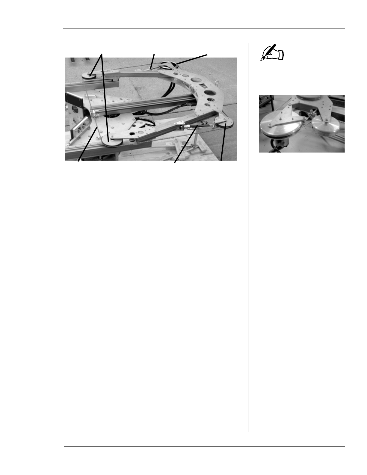
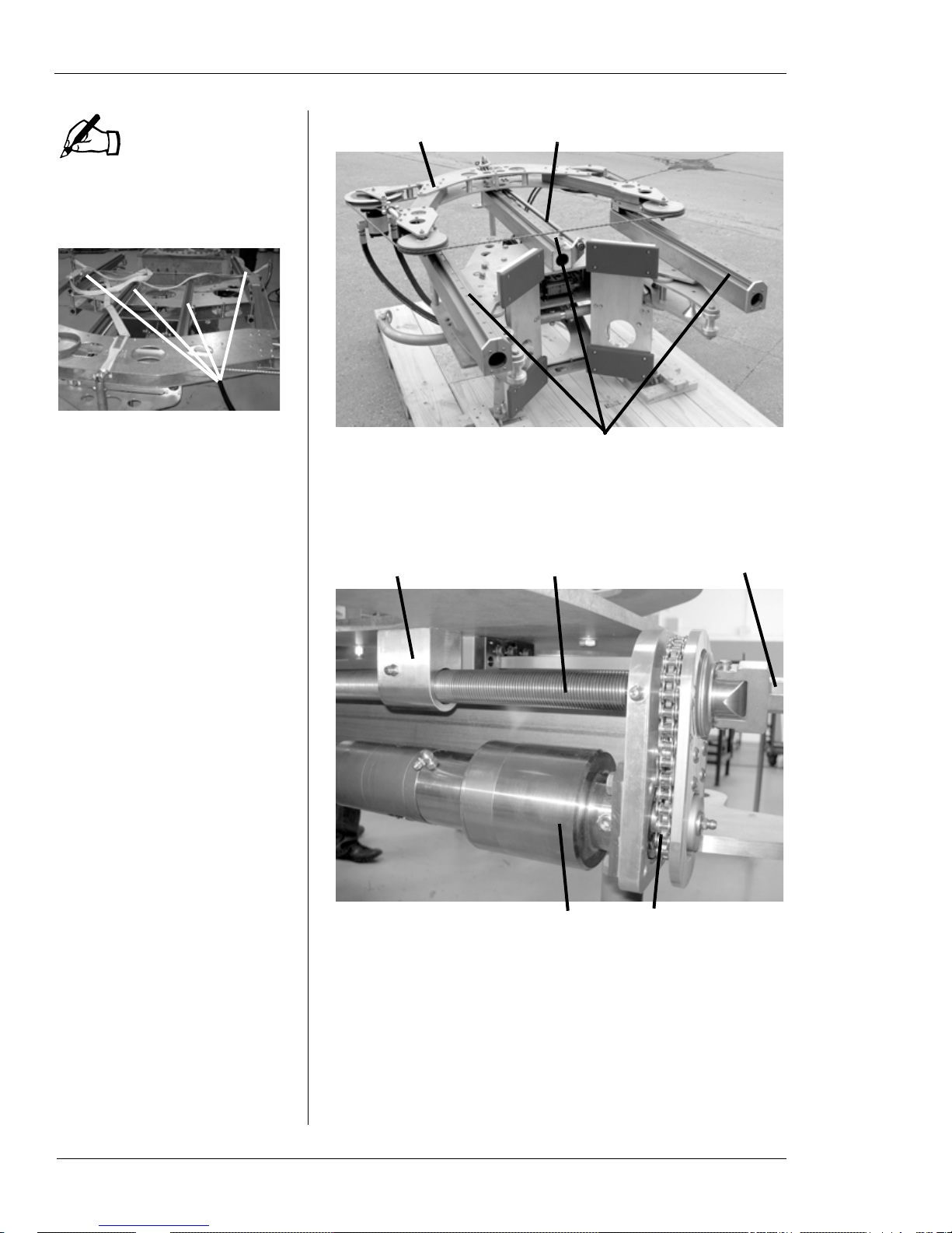
Cutting Wire Drive System
The cutting wire drive system consists of four wheels
mounted on the bow of the machine. Figure 1-1 illustrates
the drive system components.
4 Part No. 10-010-MAN, Rev. 1-0310 E.H. Wachs
Chapter 1, About the Diamond Wire Saw: Equipment Description
NOTE
Drive wheel Idler wheel
Idler wheels Drive wheel
Tension wheelDiamond wire
Tensioning knob
Tension spring
Figure 1-1. The photo shows the cutting wire drive
system components.
The WS-8460 has an additional idler wheel next to the
drive wheel.
The drive wheel is operated by the hydraulic drive motor to
turn the wire around the cutting system loop. It is mounted
on a pivoting fixture used to adjust the tension of the wire.
The tension is set using a knob on the fixture, which also
positions the wheel for installing and removing the cutting
wire.
The tension wheel is on a pivoting, spring-loaded fixture
that maintains wire tension. The other two idler wheels are
fixed at the bottom of the bow where the cutting wire
engages the pipe.
The wire is a custom-made loop for the size of the saw.
Spare wires can be ordered from E.H. Wachs.
Feed System
A feed drive mechanism on the main frame of the machine
drives the bow and cutting system up and down to perform
the cut and retract the bow after cutting. The bow rides on
feed rails and is driven by a feed screw in the center of the
frame. Figure 1-2 and Figure 1-3 show the main feed system components.
E.H. Wachs Part No. 10-010-MAN, Rev. 1-0310 5
Diamond Wire Saw User’s Manual
NOTE
Feed rails
Feed rails
Saw bow
Feed screw
Feed block Feed screw
Feed motor Driv e chain
Manual feed nut
The WS-8460 has four feed
rails, as shown below. The
other models have three rails.
Figure 1-2. The saw bow moves on thr e e feed rails on
the frame. The feed screw along the center rail drives
the bow.
6 Part No. 10-010-MAN, Rev. 1-0310 E.H. Wachs
Figure 1-3. The feed system components are shown.
The feed block is attached to the saw bow.
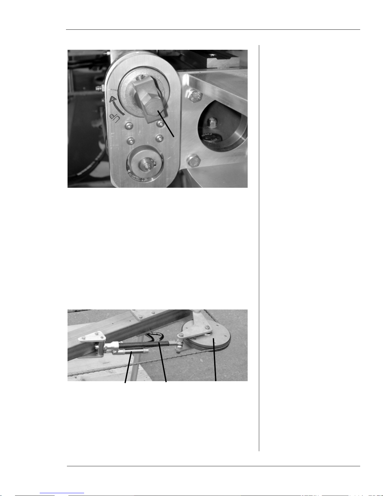
The top of the feed screw has a drive nut to allow the feed to
be operated manually, and a clutch in the top coupling disengages the feed screw if the feed drive jams or reaches the
end of travel.
Chapter 1, About the Diamond Wire Saw: Equipment Description
Manual
feed nut
Feed control actuator Tension wheelTension spring
Figure 1-4. Use the manual feed nut to move the saw
bow if it cannot be operated using hydraulic power.
T urn the nut clockwise to retract the bow away from
the workpiece.
The feed system has a self-adjusting speed control feature.
A hydraulic actuator on the tension wheel fixture measures
the deflection of the wire as it cuts. If the feed speed is too
fast, the increased wire deflection trips the actuator, which
slows down the feed rate. This allows the cutting action of
the wire to catch up. At maximum deflection of the wire, the
actuator will stop the feed motion for as long as necessary.
Figure 1-5. The actuator controls the feed rate by
measuring the deflection of the cutting wire.
E.H. Wachs Part No. 10-010-MAN, Rev. 1-0310 7
Diamond Wire Saw User’s Manual
Clamping
cylinder
Clamping
motion
Clamping arm
pivots to contact pipe
Clamping System
An adjustable clamping system allows you to configure the
machine for pipe sizes within each model’s range. The two
clamping arms are attached to the main frame with twopronged forked pins that are removable to reposition the
arms.
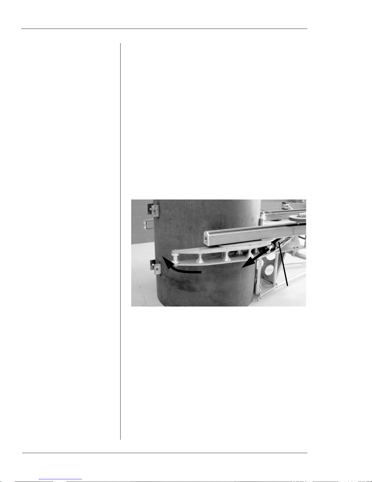
The clamping arms are engaged by hydraulic cylinders
mounted to the frame. When the cylinder rods are extended,
the clamps pivot inward to grip the underside of the pipe
and hold the machine securely to it. Figure 1-6 illustrates
the clamping operation.
See “Adjusting Clamp Arms for the Pipe Size” later in this
chapter for information on the clamp position settings for
each wire saw model.
8 Part No. 10-010-MAN, Rev. 1-0310 E.H. Wachs
Figure 1-6. The photo shows the wire saw in position
for clamping on a test workpiece. When the hydraulic
cylinder is extended, the clamp arm pivots and closes
on the pipe. Both clamping arms operate together.
Chapter 1, About the Diamond Wire Saw: Equipment Description
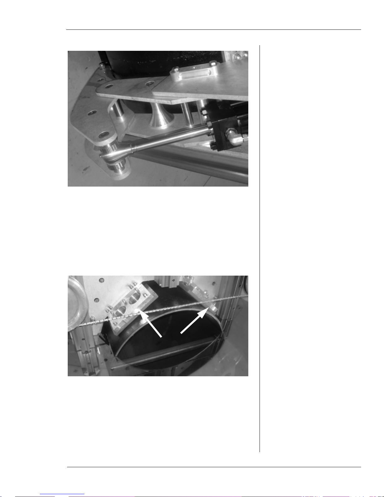
Figure 1-7. The photo shows the clamping cylinder
extended and the clamp arm secured against the pipe.
The frame of the machine has clamp shoes attached that the
machine rests upon when installed on the pipe. These shoes
are made of a compressible composite material that deforms
slightly under pressure to create a secure, slip-free grip on
the pipe when the machine is clamped.
Figure 1-8. The front mounting shoes are shown.
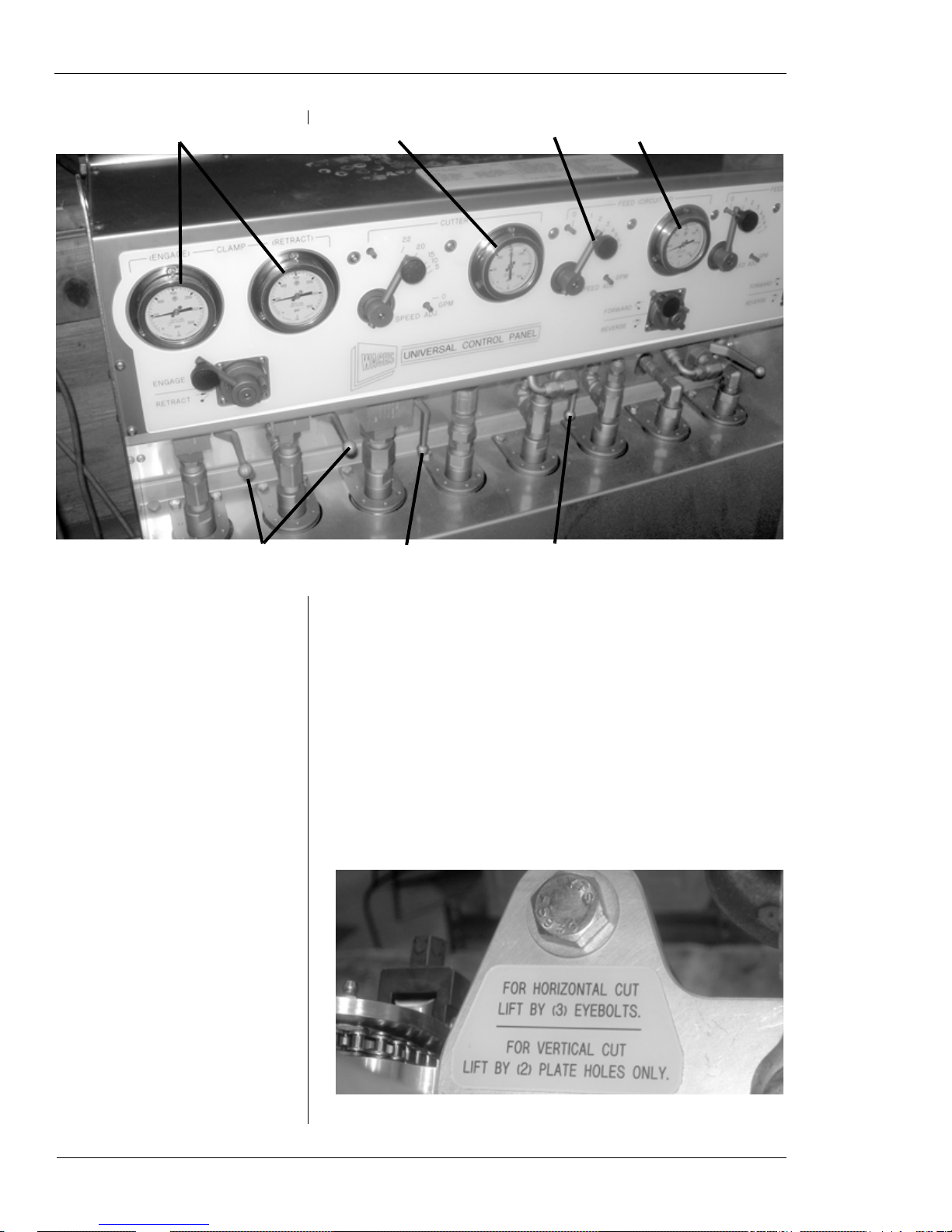
Topside Control Panel
Figure 1-9 illustrates the controls used to operate the subsea
wire saw. Chapter 3 includes detailed instructions.
E.H. Wachs Part No. 10-010-MAN, Rev. 1-0310 9
Diamond Wire Saw User’s Manual
Clamp pressure gauges
Clamp
direction
Cutter
speed
Cutter pressure gauge
Feed speed Feed pressure gauge
Feed
direction
Clamping flow levers (engage
both at once—shown closed
under pressure)
Feed flow lever
(shown open)
Cutter flow lever
(shown open)
Rigging the Machine
A rigging instruction label is attached to the top of the
machine frame on WS-164 through WS-5230 models. See
the end of this section for information on rigging the WS8460 model.
Figure 1-9. The photo shows the controls on the topside control unit. (The fourth cir cuit, to the far right, is
not used with the subsea wire saw.)
10 Part No. 10-010-MAN, Rev. 1-0310 E.H. Wachs
Figure 1-10. The rigging label is on top of the frame.
Chapter 1, About the Diamond Wire Saw: Equipment Description
IMPORTANT: Do not attach to this hook
when lifting the machine vertically!
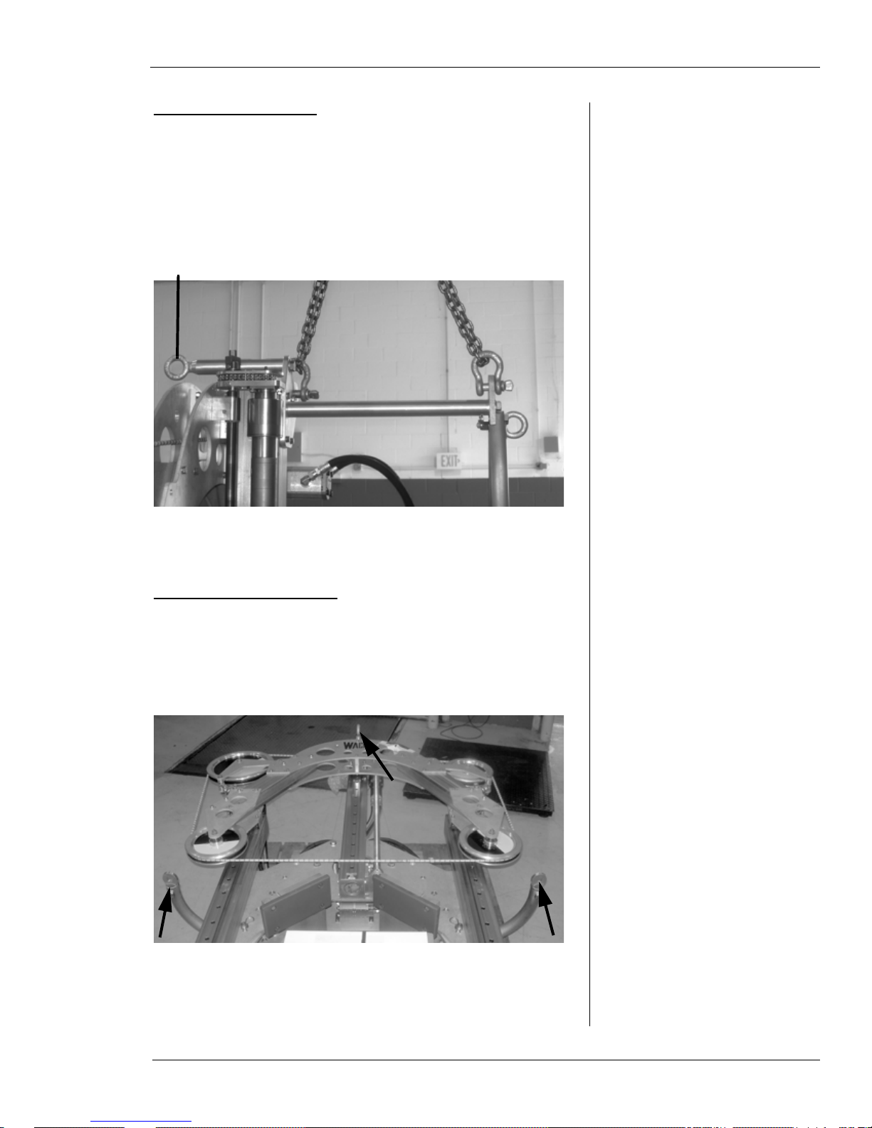
Lifting for Vertical Cut
Attach the machine to the lifting device using chains on the
top lift hooks. Tip the machine up to a vertical position, then
pick it up. Make sure the chains are the appropriate length to
hold the machine reasonably straight.
Figure 1-11. To position the machine vertically on the
pipe, attach to the two top lift hooks.
Lifting for Horizontal Cut
With the machine positio ned horizontal on the floor or deck,
attach a lift to the two hooks on the lift bar and the front
hook on top of the frame.
Figure 1-12. To position the machine horizontally on
the pipe, attach to the two lift bar hooks and the front
hook on the top.
E.H. Wachs Part No. 10-010-MAN, Rev. 1-0310 11
Diamond Wire Saw User’s Manual
Lift vertically from this point only
Lift horizontally from these three points
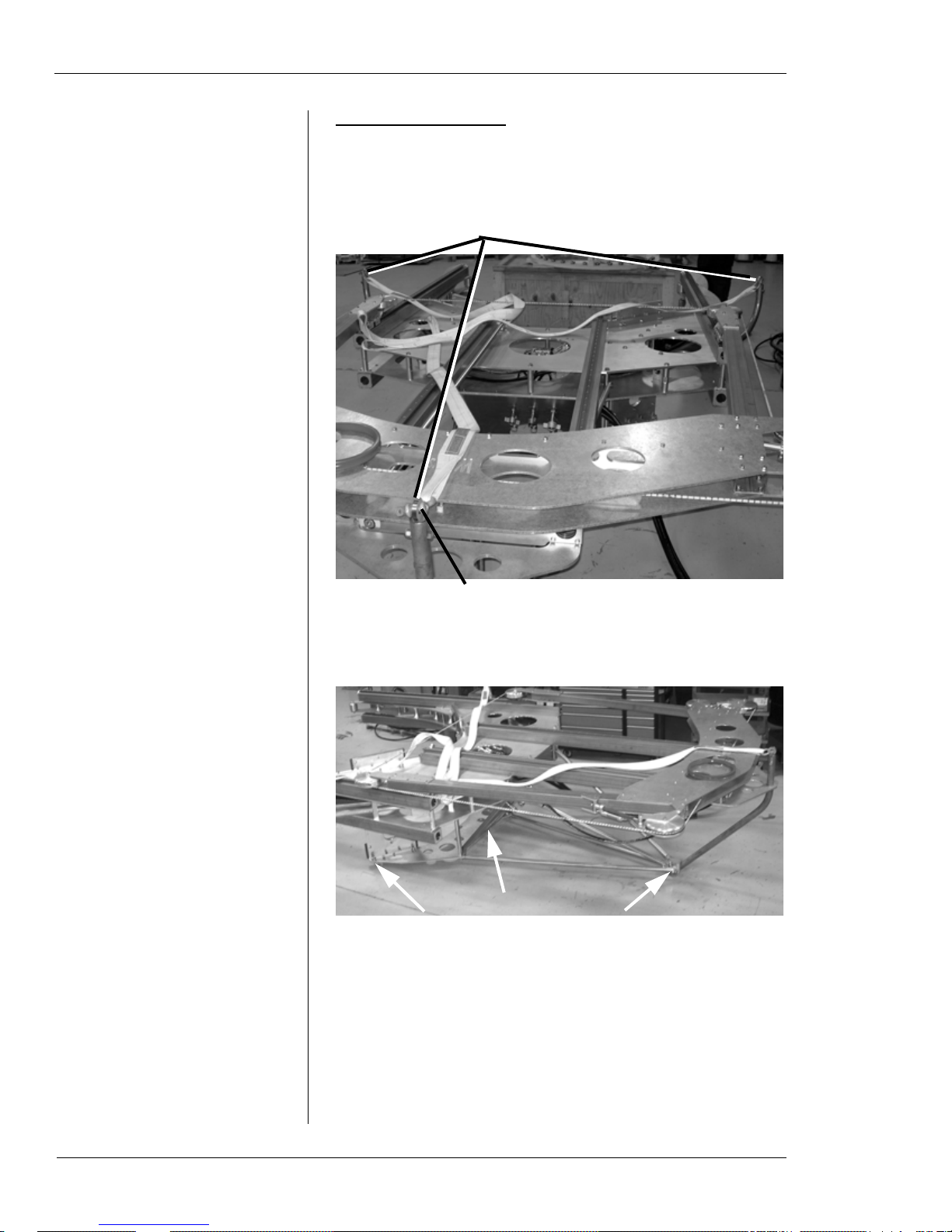
Rigging the WS-8460
You can lift the WS-8460 saw vertically, or in either horizontal orientation. See the following figures for lift points.
Figure 1-13. Use the lift points indicated to lift the
machine horizontally or vertically.
Figure 1-14. To lift the machine horizontally from the
other side, use the three points indicated in the photo
(third point is out of view under frame).
Storing the Machine
Store the machine sitting horizontal with the front of it (the
side with the Wachs logo) facing up. For long-term storage,
12 Part No. 10-010-MAN, Rev. 1-0310 E.H. Wachs

Chapter 1, About the Diamond Wire Saw: Operating Envelope
clean and dry the machine thoroughly, then cover it with a
waterproof cover.
You can leave the wire installed on the machine during storage. Keep normal tension on the wire to hold it in place.
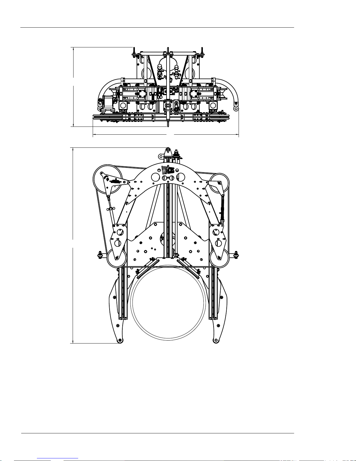
OPERATING ENVELOPE
The table below and the drawing on the next page describe
the operating envelope for all four diamond wire saw models. The “DIM” column in the table refers to the labeled
dimensions on the drawing. “Stroke” is the feed distance of
the saw bow.
Table 2: Operating Envelope Dimensions
Model DIM Inches MM
WS-164
WS-3012
WS-3616
WS-5230
A 48.5 1232
B28.0711
C 63.8 1621
Stroke 22.9 582
A 63.8 1621
B 34.9 886
C 82.6 2098
Stroke 39.0 991
A 69.6 1768
B 38.0 965
C 93.5 2375
Stroke 43.9 1115
A 87.4 2220
B 48.9 1242
C 131.0 3327
Stroke 61.9 1572
WS-8460
Stroke 97.8 2484
E.H. Wachs Part No. 10-010-MAN, Rev. 1-0310 13
A 119.0 3023
B46.51181
C 205.25 5213
Diamond Wire Saw User’s Manual
A
B
C
14 Part No. 10-010-MAN, Rev. 1-0310 E.H. Wachs

Chapter 2
Safety
The E.H. Wachs Company takes great pride in designing
and manufacturing safe, high-quality products. We make
user safety a top priority in the design of all our products.
Chapter 2, Safety
In This Chapter
OPERATOR SAFETY
SAFETY LABELS
Read this chapter carefully before operating the subsea wire
saw. It contains important safety instructions and recommendations.
OPERATOR SAFETY
WARNING: The cutting wire spins at very high speed. If
the wire breaks, segments of the wire can fragment and be
thrown from the machine at dangerous speeds. When operating the machine topside, stay a safe distance from the
machine, or behind a protective barrier. Divers should stay
a safe distance from the machine when it is running. Seri-
ous injury or death could result from contact with the
wire or as a result of the wire breaking.
Follow these guidelines for safe operation of the equipment.
• READ THE OPERATING MANUAL. Make sure
you understand all setup and operating instructions
before you begin.
• INSPECT MACHINE AND ACCESSORIES.
Before starting the machine, look for loose bolts or
nuts, leaking lubricant, rusted components, and any
other physical conditions that may affect operation.
Look for this symbol throughout the
manual. It indicates
a personal injury
hazard.
E.H. Wachs Part No. 10-010-MAN, Rev. 1-0310 15
Diamond Wire Saw User’s Manual
Properly maintaining the machine can greatly decrease
the chances for injury.
• ALWAYS READ PLACARDS AND LABELS. Make
sure all placards, labels, and stickers are clearly legible
and in good condition. You can purchase replacement
labels from E.H. Wachs Company.
• KEEP CLEAR OF MOVING PARTS. Keep hands,
arms, and fingers clear of all rotating or moving parts.
Always turn machine off before doing any adjustments
or service.
• SECURE LOOSE CLOTHING AND JEWELRY.
Secure or remove loose-fitting clothing and jewelry , and
securely bind long hair, to prevent them from getting
caught in moving parts of the machine.
• KEEP WORK AREA CLEAR. Keep all clutter and
nonessential materials out of the work area. Only people
directly involved with the work being performed should
have access to the area.
Safety Symbols
This icon is displayed with any safety alert that indicates a
personal injury hazard.
WARNING
This safety alert indicates a potentially hazardous situation
that, if not avoided, could result in death or serious injury.
CAUTION
This safety alert, with the personal injury hazard symbol,
indicates a potentially hazardous situation that, if not
avoided, could result in minor or moderate injury.
16 Part No. 10-010-MAN, Rev. 1-0310 E.H. Wachs
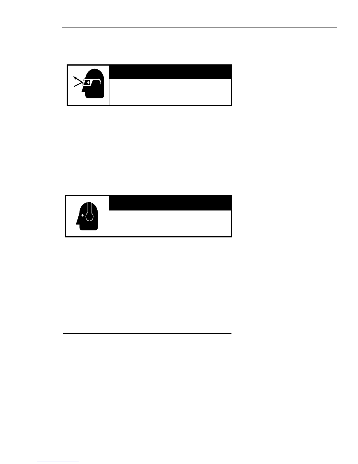
Protective Equipment Requirements
Always wear impact resistant eye protection while operating or working near
this equipment.
WARNING
CAUTION
Personal hearing protection is recommended when operating or working near
this tool.
For additional information on eye and face protection, refer
to Federal OSHA regulations, 29 Code of Federal Regulations, Section 1910.133., Eye and Face Protection and
American National Standards Institute, ANSI Z87.1, Occupational and Educational Eye and Face Protection. Z87.1 is
available from the American National Standards Institute,
Inc., 1430 Broadway, New York, NY 10018.
Chapter 2, Safety: Safety Labels
Hearing protectors are required in high noise areas, 85 dBA
or greater . The operation of other tools and equipment in the
area, reflective surfaces, process noises, and resonant structures can increase the noise level in the area. For additional
information on hearing protection, refer to Federal OSHA
regulations, 29 Code of Federal Regulations, Section
1910.95, Occupational Noise Exposure and ANSI S12.6
Hearing Protectors.
SAFETY LABELS
There is no safety labeling on the subsea wire saw.
E.H. Wachs Part No. 10-010-MAN, Rev. 1-0310 17

Diamond Wire Saw User’s Manual
18 Part No. 10-010-MAN, Rev. 1-0310 E.H. Wachs

Chapter 3
Operating
Instructions
TENSIONING THE CUTTING WIRE
You should have the wire installed according to the maintenance instructions in Chapter 4.
At the tension wheel fixture, check the start lines on
1.
the feed control actuator. When there is no tension on
the wire, the actuator rod will be retracted and the
start lines will be offset.
Chapter 3, Operating Instructions
In This Chapter
TENSIONING THE CUTTING
IRE
W
ADJUSTING CLAMP ARMS FOR
THE PIPE SIZE
CONNECTING THE HYDRAULIC
OSES
H
MOUNTING THE MACHINE ON
THE PIPE
PERFORMING THE CUT
REMOVING THE MACHINE
Figure 3-1. With no tension on the wire, the feed
actuator start lines will be offset.
E.H. Wachs Part No. 10-010-MAN, Rev. 1-0310 19
Diamond Wire Saw User’s Manual
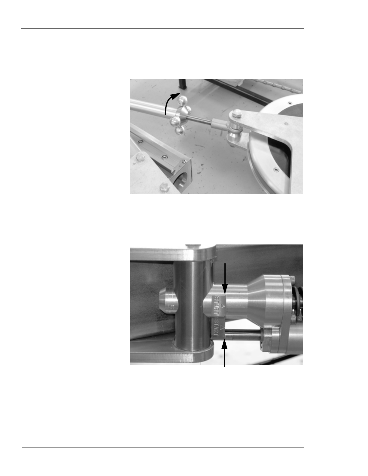
Tighten the drive wheel tensioning knob, as shown in
2.
Figure 3-2, until you can see the line on the springloaded driver wheel, Figure 3-3.
Figure 3-2. Turn the tension knob on the drive wheel
fixture to incr ease the tension on the wire. (Depending
on the exact length of the wire, about 3-4” of the scr ew
will be visible when the tension is set correctly.)
Figure 3-3. When the wire is properly tensioned, the
start lines will be lined up together.
20 Part No. 10-010-MAN, Rev. 1-0310 E.H. Wachs
You should be able to deflect the wire fairly easily by
3.
pushing it up between the idler wheels. Push it in far
enough to compress the tension spring, and make sure
the actuator rod extends into the slot in the shaft.
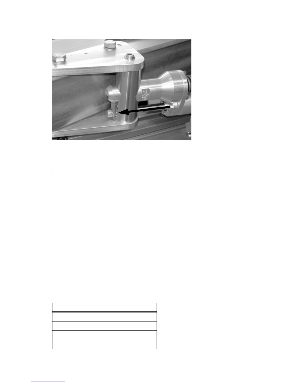
Chapter 3, Operating Instructions: Adjusting Clamp Arms for the Pipe Size
Figure 3-4. When you push the wire to deflect it, the
actuator rod will extend.
ADJUSTING CLAMP ARMS FOR THE PIPE SIZE
The clamp arms are attached to the main frame using forked
pins that go through two holes in the frame. Multiple sets of
holes allow the arms to be mounted in various positions.
The hole pairs for each position are stamped with the size of
the largest pipe for that position. Refer to the following sections for the pipe size settings for each saw model.
WS-164 Pipe Size Settings
Table 1 describes the pipe size settings for the WS-164
model.
Table 1: Pipe Size Ranges for Clamping
Arm Positions—WS-164
Size Stamp Pipe Diameter Range
7 4” to 7” (102-178 mm)
10 7” to 10” (178-254 mm)
13 10” to 13” (254-330 mm)
16 13” to 16” (330-406 mm)
E.H. Wachs Part No. 10-010-MAN, Rev. 1-0310 21
Diamond Wire Saw User’s Manual
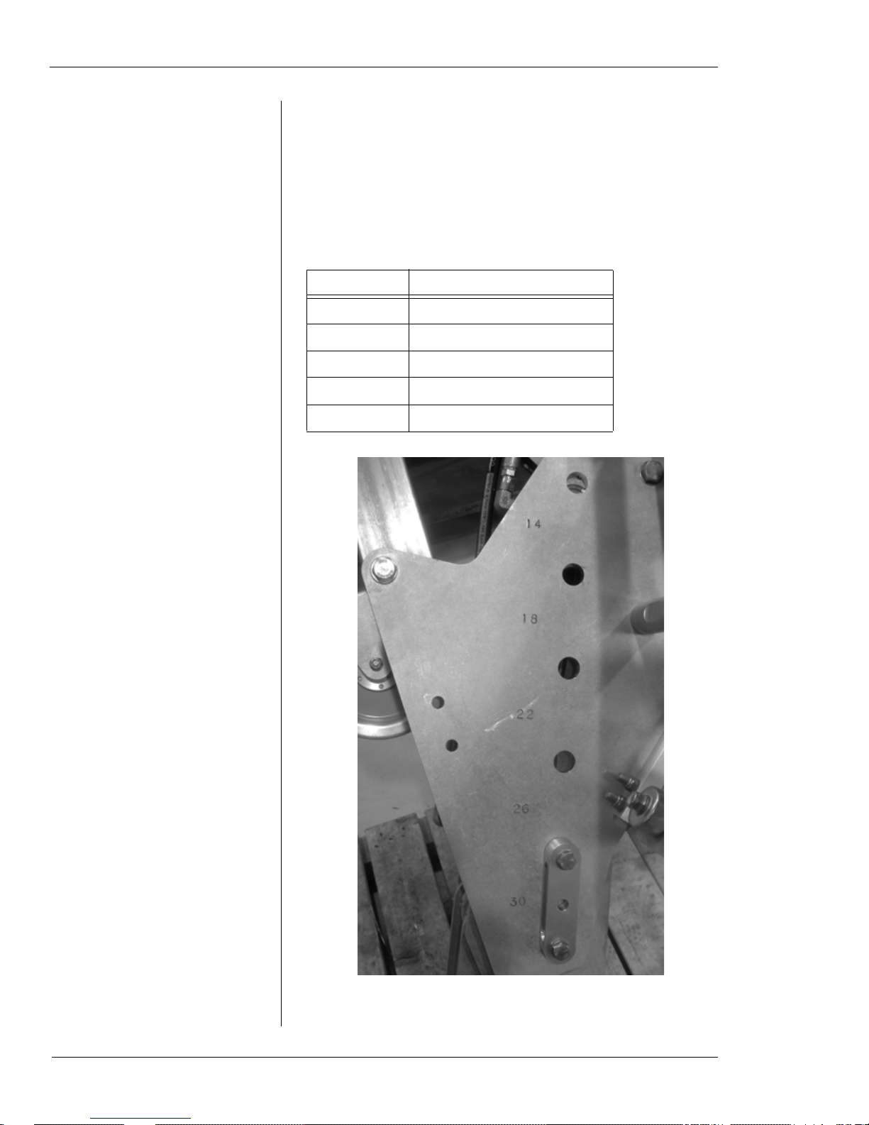
WS-3012 Pipe Size Settings
T able 2 and Figure 3-5 describe the pipe size settings for the
WS-3012 model.
Table 2: Pipe Size Ranges for Clamping
Arm Positions—WS-3012
Size Stamp Pipe Diameter Range
14 12” to 14” (305-356 mm)
18 14” to 18” (356-457 mm)
22 18” to 22” (457-559 mm)
26 22” to 26” (559-660 mm)
30 26” to 30” (660-762 mm)
22 Part No. 10-010-MAN, Rev. 1-0310 E.H. Wachs
Figure 3-5. The photo shows the size stamps on the
WS-3012 model. The pin is in the 26-30” position.
Chapter 3, Operating Instructions: Adjusting Clamp Arms for the Pipe Size
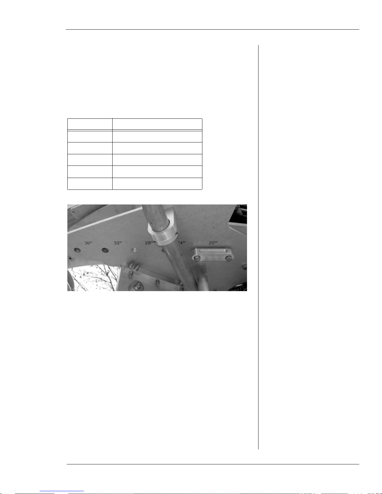
WS-3616 Pipe Size Settings
T able 3 and Figure 3-6 describe the pipe size settings for the
WS-3616 model.
Table 3: Pipe Size Ranges for Clamping
Arm Positions—WS-3616
Size Stamp Pipe Diameter Range
20 16” to 20” (406-508 mm)
24 20” to 24” (508-610 mm)
28 24” to 28” (610-711 mm)
32 28” to 32” (711-813 mm)
36 32” to 36” (813-914 mm)
Figure 3-6. The photo shows the size stamps on the
WS-3616 model. The pin is in the 16-20” position.
E.H. Wachs Part No. 10-010-MAN, Rev. 1-0310 23
Diamond Wire Saw User’s Manual
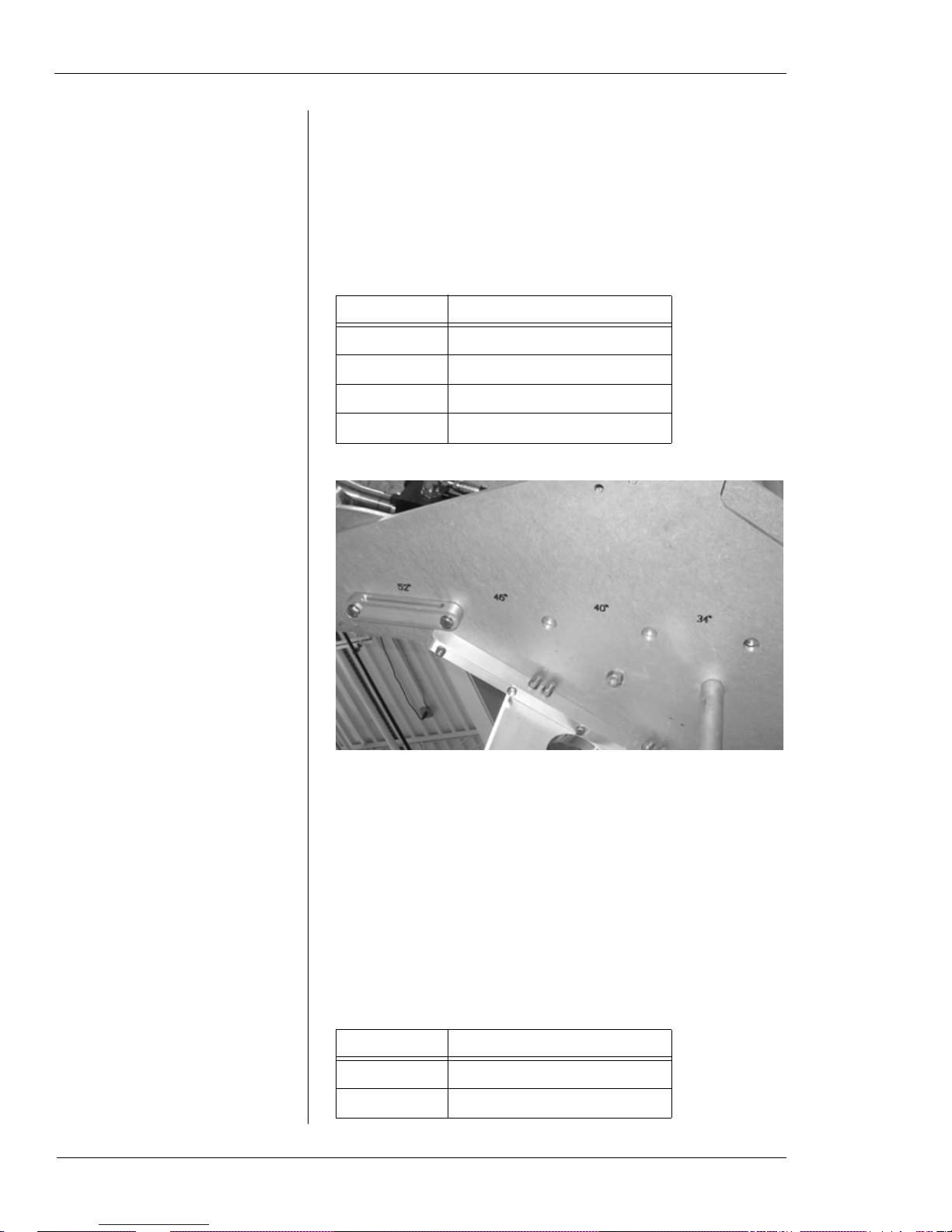
WS-5230 Pipe Size Settings
T able 4 and Figure 3-7 describe the pipe size settings for the
WS-5230 model.
Table 4: Pipe Size Ranges for Clamping
Arm Positions—WS-5230
Size Stamp Pipe Diameter Range
34 30” to 34” (762-864 mm)
40 34” to 40” (864-1016 mm)
46 40” to 46” (1016-1168 mm)
52 46” to 52” (1168-1321 mm)
24 Part No. 10-010-MAN, Rev. 1-0310 E.H. Wachs
Figure 3-7. The photo shows the size stamps on the
WS-5230 model. The pin is in the 46-52” position.
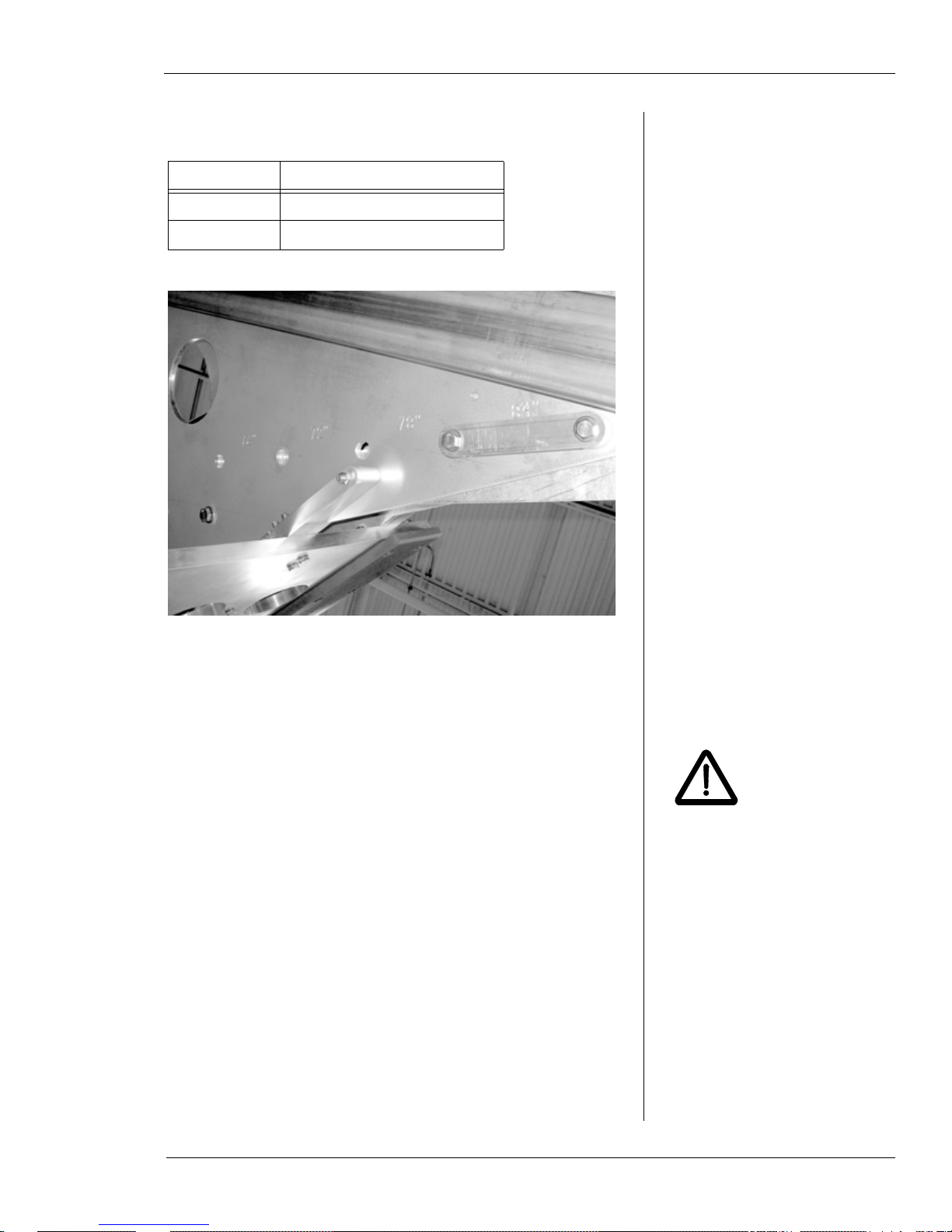
WS-8460 Pipe Size Settings
T able 5 and Figure 3-8 describe the pipe size settings for the
WS-8460 model.
Table 5: Pipe Size Ranges for Clamping
Arm Positions—WS-8460
Size Stamp Pipe Diameter Range
66 60” to 66” (152 4-1676 mm)
72 66” to 72” (167 6-1829 mm)
Chapter 3, Operating Instructions: Adjusting Clamp Arms for the Pipe Size
WARNING
Table 5: Pipe Size Ranges for Clamping
Arm Positions—WS-8460
Size Stamp Pipe Diameter Range
78 72” to 78” (1829 -1981 mm)
84 78” to 84” (1981 -2134 mm)
Figure 3-8. The photo shows the size stamps on the
WS-8460 model. The pin is in the 78-84” position.
Positioning the Clamp Arms
Make sure the saw is sitting horizontally on a level surface
before you adjust the clamp arms.
Remove the spring clips from both pin ends of the
1.
forked pin, then pull the forked pin out of the frame.
Do not attempt to change the
clamp arm positions while the
saw is in a vertical position.
The clamp arms may fall
when the pins are removed,
resulting in personal injury
and equipment damage.
E.H. Wachs Part No. 10-010-MAN, Rev. 1-0310 25

Diamond Wire Saw User’s Manual
Figure 3-9. Remove the spring clips fr om both ends of
the forked pin, then pull the pin out from the other
side.
Slide the clamp arm assembly so that the mounting
2.
holes line up with the appropriate hole pair for the
pipe size you are cutting.
Insert the forked pin through the back of the machine.
3.
Figure 3-10. Insert the forked pin through the hole
pair for the pipe size range (in this case, 46-52”) you
are cutting.
Insert the spring clips in the forked pin on the front of
4.
the machine.
26 Part No. 10-010-MAN, Rev. 1-0310 E.H. Wachs

Chapter 3, Operating Instructions: Connecting the Hydraulic Hoses
CAUTION
WARNING
Clamp circuit
pressure
Feed circuit
pressure
Cutting drive
circuit pressure
Clamp circuit
return
Feed circuit
return
Cutting drive
circuit return
Set the position of the other clamp arm to the same
5.
location.
CONNECTING THE HYDRAULIC HOSES
Connect the hydraulic hoses from the topside control panel
(TCP) to the hydraulic bulkhead on the machine, as indicated in Figure 3-11.
Before lowering the machine subsea, test all three drive circuits to make sure they are working.
Make sure both clamping
arms are set at the same
position. If they are not the
same, the machine may not
clamp securely on the pipe.
Damage to the machine
could result.
The cutting wire spins at very
high speed. If the wire
breaks, segments of the wire
can fragment and be thrown
from the machine at dangerous speeds. Stay a safe distance from the machine, or
behind a protective barrier,
when operating it topside.
Serious injury or death
could result from contact
with the wire or as a result
of the wire breaking.
The ports marked “A” are pressure lines from the
TCP; the ports marked “B” are return lines to the
TCP.
E.H. Wachs Part No. 10-010-MAN, Rev. 1-0310 27
Figure 3-11. Attach the hydraulic hoses as shown.

Diamond Wire Saw User’s Manual
CAUTION
NOTE
CAUTION
Lift the machine ONLY on the
lifting eyes provided. Lifting
on any other component
could damage the machine.
The flow on the clamp circuit
is set internally at 4 gpm.
MOUNTING THE MACHINE ON THE PIPE
See “Rigging the Machine” in Chapter 1 for instructions on
lifting the machine to position it for horizontal or vertical
cuts.
• Attach lifting shackles to the appropriate lift eyes for the
orientation of the machine.
• Before lowering the machine subsea to the cutting location, make sure the clamping arms are fully open.
Set the controls on the TCP as follows:
• All flow levers up (flow off).
• Cutter speed knob to 17.5 gpm
• Feed speed knob to 1.5 gpm
• (Clamp flow is preset to 4 gpm)
• Clamp direction to ENGAGE
• Feed direction to FORWARD
• (Cutter direction is preset to forward).
As you operate the machine,
check the clamping pressure
frequently to make sure it
stays above 1700 psi. If it
gets too low, stop the
machine and reclamp it to the
pipe.
Align the machine at the desired cut line, perpendicu-
1.
lar to the center axis of the pipe. The clamping arms
should extend around the pipe and the mounting shoes
should be against the pipe, or close to it.
Start the hydraulic power unit. Set it to provide 22
2.
gpm flow at 3000 psi.
Push both clamping flow levers down simultaneously.
3.
Watch the clamping pressure gauges to ensure that the
pressure is within 1900-2200 psi.
When the clamping arms are fully clamped and the
4.
pressure is within 1900-2200 psi, pull both clamping
flow levers up to lock the holding pressure. The pressure will drop quickly to 1850 psi and then slowly to
about 1600 psi.
Repeat the clamp sequence three times. The pressure
5.
should hold above 1700 psi.
28 Part No. 10-010-MAN, Rev. 1-0310 E.H. Wachs

PERFORMING THE CUT
WARNING
Push the feed flow lever down to open the feed circuit.
1.
Chapter 3, Operating Instructions: Performing the Cut
The cutting wire spins at very
high speed. If the wire
breaks, segments of the wire
can fragment and be thrown
from the machine at dangerous speeds. Make sure all
personnel are at a safe distance before starting the cutting drive. Serious injury or
death could result from
contact with the wire or as
a result of the wire breaking.
Figure 3-12. Push the feed flow lever down to supply
power to the feed drive.
Set the feed speed knob to 2.5 gpm.
2.
Figure 3-13. Push the feed speed knob down to
2.5 gpm.
E.H. Wachs Part No. 10-010-MAN, Rev. 1-0310 29

Diamond Wire Saw User’s Manual
NOTE
NOTE
The larger the pipe size, the
longer it will take to feed the
cutting wire close to the pipe.
This is because smaller pipes
fit closer between the mounting shoes.
V isually monitor the position of the cutting wire as the
3.
bow feeds toward the pipe. When the wire is within
1/4” of the pipe surface, pull the feed flow lever up to
turn off the feed drive.
Push the cutting drive flow lever down to open the
4.
cutting drive circuit.
At the minimum operating
speed, the drive wheel will be
spinning at about 1500 RPM.
Figure 3-14. Push the cutting flow lever down to supply power to the cutting drive.
Start with the cutting speed knob at 18 gpm. Visually
5.
ensure that the wheels are spinning.
30 Part No. 10-010-MAN, Rev. 1-0310 E.H. Wachs

Chapter 3, Operating Instructions: Performing the Cut
NOTE
Figure 3-15. Push the cutting speed knob up to
increase the drive wheel speed.
Push the feed flow lever down to start feeding the wire
6.
into the pipe. The feed speed knob should be at 2.5
gpm.
As the wire enters the cut, increase the cutting speed
7.
by moving the cutting speed knob. Do not go above 19
gpm.
During cutting, the feed control actuator on the ten-
8.
sion wheel fixture adjusts the feed rate to keep the saw
from overfeeding. It should not be necessary to adjust
the feed rate at the TCP.
Continue until the wire has completely severed the
9.
pipe.
Pull the feed flow lever up to turn off the feed drive.
10.
The feed drive will travel
about 2 inches beyond the
bottom of the largest pipe
size.
E.H. Wachs Part No. 10-010-MAN, Rev. 1-0310 31

Diamond Wire Saw User’s Manual
Figure 3-16. Push the feed flow lever up to 0 and pull
the feed flow lever up to turn off the feed drive.
Pull the cutter flow lever up to turn off the cutter drive.
11.
Figure 3-17. Pull the cutter flow lever up to turn off
the cutter.
32 Part No. 10-010-MAN, Rev. 1-0310 E.H. Wachs

REMOVING THE MACHINE
Set the feed direction knob on the TCP to REVERSE.
1.
Chapter 3, Operating Instructions: Performing the Cut
Figure 3-18. Set the feed direction knob to REVERSE.
Push the feed flow lever down to open the feed circuit.
2.
Figure 3-19. Push the feed flow lever down to supply
power to the feed drive.
Push the feed speed knob down to 6.5 gpm (maximum
3.
flow).
E.H. Wachs Part No. 10-010-MAN, Rev. 1-0310 33

Diamond Wire Saw User’s Manual
NOTE
It will take about 30 minutes
to retract the feed drive on a
36 inch pipe.
Figure 3-20. Push the feed speed knob down to the
maximum setting.
When the saw bow is back at its home position, pull
4.
the feed flow lever up to stop the feed drive.
34 Part No. 10-010-MAN, Rev. 1-0310 E.H. Wachs
Figure 3-21. Pull the feed flow lever up to turn off the
feed drive.
Rig the shackles to the overhead lift. Lift just enough
5.
to put tension on the chains and secure the machine.
Push the clamping direction knob to the RETRACT
6.
position.

Chapter 3, Operating Instructions: Performing the Cut
Figure 3-22. Set the clamping direction knob to
RETRACT.
Push both clamping flow levers down simultaneously
7.
until the clamp arms are fully open. The right (return
pressure) gauge reading will equal the system pressure. Pull the clamping flow levers back up.
Lift the machine off the pipe. Move it to the next cut-
8.
ting location or bring it topside if you are finished.
E.H. Wachs Part No. 10-010-MAN, Rev. 1-0310 35

Diamond Wire Saw User’s Manual
36 Part No. 10-010-MAN, Rev. 1-0310 E.H. Wachs

Chapter 4
CAUTION
Maintenance
Chapter 4, Maintenance
In This Chapter
LUBRICATION
LUBRICATION
Every time you use the machine, lubricate the following
components.
Slowly pump multi-purpose No. 2 EP marine grease
1.
into the grease fittings on each of the 4 wheel hubs.
(Do NOT use AquaLube on the wheel hubs.)
REPLACING THE CUTTING WIRE
REPLACING THE MOUNTING
S
HOES
REPLACING THE WHEEL LINERS
BLEEDING THE FEED TENSION
ONTROL
C
Figure 4-1. Each wheel hub has a grease fitting.
Pump AquaLube into the grease fittings on the feed
2.
gears, feed motor, and feed block (4 fittings).
E.H. Wachs Part No. 10-010-MAN, Rev. 1-0310 37
Do not directly apply lubricant
to the feed screw.

Diamond Wire Saw User’s Manual
Feed block Feed motor Feed gears
Figure 4-2. Grease the feed components shown at the
top of the feed system.
Pump AquaLube into the grease fitting on the feed
3.
screw mount at the bottom of the screw.
Figure 4-3. Gr ease the fitting at the bottom of the feed
screw.
4.
38 Part No. 10-010-MAN, Rev. 1-0310 E.H. Wachs
Pump AquaLube into the grease fittings on the cylinder rod ends until grease is visible.

Chapter 4, Maintenance: Replacing the Cutting Wire
CAUTION
Figure 4-4. Both clamping cylinders have a gr ease fitting on the rod end.
REPLACING THE CUTTING WIRE
Start with the saw bow retracted all the way to the top of the
frame. See special instructions at the end of this section for
the WS-8460 model.
Turn the tension knob on the drive wheel fixture all
1.
the way down to release the tension on the wire.
Wear gloves when handling
the wire. The abrasive surfaces are sharp and could cut
your hands.
Figure 4-5. Turn the tensioning knob all the way
down on the screw to loosen the wire.
Slip the wire off the drive wheel, then remove it from
2.
the other wheels.
E.H. Wachs Part No. 10-010-MAN, Rev. 1-0310 39

Diamond Wire Saw User’s Manual
Cutting direction
Arrowhead
Shoulders
Cutting direction
NOTE
Different brands of wire have different markings to
3.
indicate cutting direction. Look at the new wire
closely to determine direction.
Figure 4-6. This wire has molded arrows indicating
the cutting direction.
The drive wheel fixture is
stamped with an arrow showing the direction of rotation.
Figure 4-7. This type of wire has arrowheads molded
into the plastic coating. The dark “shoulder” of the
cutting bead should trail the bead as the wire cuts.
Place the new wire over the wheels, in reverse order of
4.
removing the wire. Be sure to mount it so that the
arrows are in the direction of travel.
Figure 4-8. Install the wir e so that the arrows point in
the direction of travel, as shown.
40 Part No. 10-010-MAN, Rev. 1-0310 E.H. Wachs

Chapter 4, Maintenance: Replacing the Cutting Wire
Remove nut
and shaft
Pull wheel
out of frame
Turn the drive wheel tension knob until the wire starts
5.
to tighten and stays on the wheels.
To prepare the machine for a new cut, set the wire ten-
6.
sion as described in the operating instructions in
Chapter 3.
Mounting the Wire on the WS-8460
The WS-8460 has an additional idler wheel next to the drive
wheel. This idler wheel needs to be removed to replace the
cutting wire.
If there is a wire on the saw, turn the drive wheel ten-
1.
sion knob to fully release the tension on the wire.
Remove the nut from the idler wheel shaft, and pull
2.
out the shaft.
Pull the wheel in its housing out of the frame. Keep
3.
the wheel and housing assembled; the housing can
come off once the shaft is removed.
Figure 4-9. Remove the wheel shaft nut and pull the
shaft out from the bottom, then remove the wheel
assembly from the frame.
You can now remove the wire from the saw. Install a
4.
new wire as described above, then replace the idler
wheel and re-install the shaft and nut.
E.H. Wachs Part No. 10-010-MAN, Rev. 1-0310 41

Diamond Wire Saw User’s Manual
REPLACING THE MOUNTING SHOES
You may have to replace the mounting shoes if they are
damaged or worn. Four screws attach each shoe to the
frame.
Figure 4-10. The four screws indicated hold the shoe
to the machine frame.
Remove the nuts on the four screws holding the shoe
1.
in place.
Remove the shoe.
2.
Put the new shoe in place and replace the screws.
3.
Replace the nuts and tighten them securely.
4.
REPLACING THE WHEEL LINERS
The liners on the cutting wire wheels are durable and longlasting. They may wear out after extensive use, or be damaged if the saw malfunctions. If necessary, replace them
using the following procedure.
The tension wheel and 2 idler wheels are identical. The
drive wheel is assembled differently than the others.
42 Part No. 10-010-MAN, Rev. 1-0310 E.H. Wachs

Tension and Idler Wheels
NOTE
NOTE
Remove the cutting wire before taking off any of the
wheels.
Remove the nut on the end of the hub bolt and pull the
1.
bolt out of the wheel mounting fixture.
Chapter 4, Maintenance: Replacing the Wheel Liners
Some models have covers
over the wheels. You can
separate and remove the
cover after you take the
wheel out of the wheel
mounting fixture.
Figure 4-11. Remove the hub bolt to take off the
wheel. The bolt head is on top in this view , with the nut
on the bottom of the fixture.
Remove the wheel from its mounting fixture and set it
2.
on a work surface. You can work on either side of the
wheel.
Remove the 12 screws holding the side plate in place.
3.
You only need to remove one side plate.
It may be easier to work on
the wheel if you set it on
something that supports the
side plate, with a gap for the
hub shaft to keep it from sitting on the shaft.
E.H. Wachs Part No. 10-010-MAN, Rev. 1-0310 43

Diamond Wire Saw User’s Manual
Figure 4-12. Remove the scr ews from the side plate to
take it off.
Remove the side plate.
4.
Remove the old wheel liner. You may have to pry it
5.
loose with a screwdriver.
44 Part No. 10-010-MAN, Rev. 1-0310 E.H. Wachs
Figure 4-13. Pull the liner off the wheel. You may
have to pry it with a screwdriver to get it loose.

Place the new liner on the wheel and press it down
6.
into place.
Chapter 4, Maintenance: Replacing the Wheel Liners
Figure 4-14. Put the new wheel liner on the wheel.
If you removed the shaft, replace it through the center
7.
of the wheel.
Figure 4-15. Replace the shaft through the center of
the wheel.
Replace the side plate. Line up the holes in the plate
8.
with the holes in the wheel.
E.H. Wachs Part No. 10-010-MAN, Rev. 1-0310 45

Diamond Wire Saw User’s Manual
Fasten the side plate with the 12 screws. Snug each
9.
screw, then tighten them in a criss-cross pattern to
secure the wheel evenly.
Figure 4-16. Replace the screws in the side plate.
Replace the wheel into its mounting fixture. Put the
10.
bolt through the top of the fixture, and install the nut
on the bottom. Tighten the nut securely.
Drive Wheel
Remove the cutting wire before taking off any of the
wheels.
To replace the drive wheel liner, you must first remove the
wheel and motor assembly from the saw bow using the following procedure.
Hold or support the drive wheel and hydraulic motor
1.
assembly , so that it does not fall when you remove the
fasteners holding it to the saw bow.
Loosen the set screws in the stop collars on the pivot
2.
pin and remove the pin from the frame. Be careful not
to lose the stop collars.
46 Part No. 10-010-MAN, Rev. 1-0310 E.H. Wachs

Chapter 4, Maintenance: Replacing the Wheel Liners
Pivot pin
Stop collars
Set screw
Tension rod
mounting bolt
Hub boltSpacer bolt Top plate
Figure 4-17. Loosen the set screws in the stop collars
to remove the pivot pin.
Remove the nut from the bolt holding the wheel
3.
assembly to the tension rod, then remove the bolt. The
wheel and motor assembly will be free from the saw
bow.
Figure 4-18. Remove the nut (on the bottom) of the
tension rod mounting bolt, and remove the bolt.
E.H. Wachs Part No. 10-010-MAN, Rev. 1-0310 47

Diamond Wire Saw User’s Manual
Remove the hub bolt and spacer bolt from the wheel
4.
assembly, as shown in Figure 4-18. Be careful not to
lose the spacer.
Pull the top plate off the wheel.
5.
Pull the wheel up off the motor shaft. Note the side of
6.
the wheel that mounts onto the motor; the wheel is not
reversible.
Disassemble the wheel and replace the liner as
7.
described in the previous section, “Tension and Idler
Wheels”.
Replace the wheel on the motor shaft, making sure the
8.
correct side is toward the motor.
Replace the top plate. Insert the spacer bolt through
9.
the spacer and snug it down.
Replace the hub bolt and snug it.
10.
Replace the tension rod mounting bolt through the
11.
plates and tension rod end. Put the nut on the end of
the bolt and tighten it securely.
Tighten the spacer bolt and hub bolt securely.
12.
Slide the wheel and motor assembly plates into place
13.
in the saw bow and line up the pivot pin holes.
Set the stop collars in place between the plates. Insert
14.
the pivot pin through the top plate, the stop collars,
and the bottom plate.
Holding the pivot pin in place, position the stop col-
15.
lars against the mounting plates and tighten the set
screws.
48 Part No. 10-010-MAN, Rev. 1-0310 E.H. Wachs

Chapter 4, Maintenance: Bleeding the Feed Tension Control
Pivot pin
Stop collars
Set screw
Figure 4-19. Make sure the pivot pin is through both
plates, then position the stop collars and tighten the
set screws.
BLEEDING THE FEED TENSION CONTROL
If the feed tension control mechanism is not working properly, you will need to bleed the system. Typically, the problem will be that the system overfeeds, putting too much
tension on the wire and potentially breaking it.
For this procedure, you will need to access the tension control mechanism assembly and the spring tension assembly.
Figure 4-20 shows the location of these assemblies on the
saw.
E.H. Wachs Part No. 10-010-MAN, Rev. 1-0310 49

Diamond Wire Saw User’s Manual
Spring tension
assembly
(10-010-00-435)
Tension control
mechanism assembly
(10-010-00-418)
NOTE
cross-section
Figure 4-20. The photo shows the locations of the tension control system components on the WS5230 saw
model. The assemblies are in the same location on all
models of the diamond wire saw.
The full assembly drawings
with parts lists are included in
Chapter 5.
Position the saw so that the bow is face down (oppo-
1.
site the way shown in Figure 4-20). Use blocks underneath it to avoid damaging the grease fittings.
Remove the cylinder from the spring assembly by
2.
removing ¼-28 SHCS and 1-1/4" nut. T emporarily put
the fasteners back on the cylinder . Note: SHCS is Item
14 and Nut is Item 9 on drawing 10-010-00-435,
shown in Figure 4-21.
50 Part No. 10-010-MAN, Rev. 1-0310 E.H. Wachs
Figure 4-21. The drawing illustrates the components
of the spring assembly. Item 2 is the spring assembly
cylinder.

Chapter 4, Maintenance: Bleeding the Feed Tension Control
Sight tube
End plug
Remove the rod end from the tension control mecha-
3.
nism cylinder by removing ¼-28 SHCS. Temporarily
put the SCHS back on the cylinder. Note: SHCS is
Item 20 and Rod End is Item 7 on drawing 10-010-00418, shown in Figure 4-22.
4.
5.
6.
7.
E.H. Wachs Part No. 10-010-MAN, Rev. 1-0310 51
Figure 4-22. The drawing illustrates the components
of the tension control mechanism. Item 1 is the tension
control mechanism cylinder.
If sight tube has no green fluid visible, remove end
plug and fill with 50/50 antifreeze. (Water may be
used if antifreeze is unavailable).
Open the frame bypass ball valve (Item 10 in
Figure 4-22) and the sight tube bypass ball valve (Item
11 in Figure 4-22).
Slowly cycle the tension control assembly cylinder
(Figure 4-22) back and forth 10 times.
Close the frame bypass ball valve (Item 10 in
Figure 4-22).

Diamond Wire Saw User’s Manual
Slowly cycle the tension control assembly cylinder
8.
(Figure 4-22) back and forth 10 times.
Open the frame bypass ball valve (Item 10 in
9.
Figure 4-22).
Slowly cycle the spring assembly cylinder (Figure 4-
10.
21) back and forth 10 times.
Close the frame bypass ball valve (Item 10 in
11.
Figure 4-22).
Slowly cycle the spring assembly cylinder (Figure 4-
12.
21) back and forth 10 times.
If required, fill the sight tube with 50/50 antifreeze.
13.
Open the frame bypass ball valve (Item 10 in
14.
Figure 4-22).
Close the sight tube ball valve (Item 11 in Figure 4-
15.
22).
Fully extend the spring assembly cylinder (Figure 4-
16.
21) and fully retract the tension control assembly cylinder (Figure 4-22).
Close the frame bypass ball valve (Item 10 in
17.
Figure 4-22).
Cycle either cylinder once; there should be no delayed
18.
movement of the other cylinder. If some “sponge”
exists, repeat steps 5 through 16.
Re-install both cylinders by reversing steps 2 and 3.
19.
52 Part No. 10-010-MAN, Rev. 1-0310 E.H. Wachs

Chapter 5
Parts List and
Ordering Information
Chapter 5, Parts List and Ordering Information
In This Chapter
ORDERING INFORMATION
ORDERING INFORMATION
To place an order, request service, or get more detailed
information on any E.H. Wachs products, call us at one of
the following numbers:
U.S. 800-323-8185
International: 847-537-8800
You can also visit our Web site at:
www.ehwachs.com
Ordering Replacement Parts
When ordering parts, refer to the parts lists in this chapter.
Please provide the part description and part number for all
parts you are ordering.
Repair Information
DRAWINGS AND PARTS LISTS
Please call us for an authorization number before returning
any equipment for repair or factory service. We will advise
you of shipping and handling. When you send the equipment, please include the following information:
• Your name/company name
• Your address
• Your phone number
E.H. Wachs Part No. 10-010-MAN, Rev. 1-0310 53

Diamond Wire Saw User’s Manual
• A description of the problem or the work to be done.
Before we perform any repair, we will estimate the work
and inform you of the cost and the time to complete it.
Warranty Information
Enclosed with the manual is a warranty card. Please fill out
the registration card and return to E.H. Wachs. Retain the
owner’s registration record and warranty card for your
information.
Return Goods Address
Return equipment for repair to the following address.
E.H. Wachs
600 Knightsbridge Parkway
Lincolnshire, Illinois 60069 USA
DRAWINGS AND PARTS LISTS
The drawings on the following pages illustrate the WS-164,
WS-3012, WS-3616, and WS-5230 diamond wire saws.
Each assembly drawing includes a parts list; use the part
numbers to order spare or replacement parts.
The following tables list the drawings provided for each
diamond wire saw model.
54 Part No. 10-010-MAN, Rev. 1-0310 E.H. Wachs

Chapter 5, Parts List and Ordering Information: Drawings and Parts Lists
Table 1: Common Assemblies—All WS Models
Drawing Number Description
10-010-00-412 Planetary Gear Motor
10-010-00-418 Tension Control Mechanism
10-010-00-419 Flow Divider Assembly
10-010-00-431 Frame Drive Arm
10-010-00-432 Frame Drive Wheel
10-010-00-433 Tensioning Wheel Assembly
10-010-00-434 Idler Wheel Assembly
10-010-00-435 Spring Tension Assembly
Table 2: WS-164 Assembly Drawings
Drawing Number Description
10-010-16-411 Feed Frame
10-010-16-413 Lifting Tube
10-010-16-418 Tension Control Mechanism
10-010-16-419 Flow Divider Assembly
10-010-16-224B Bulkhead Plate
Table 3: WS-3012 Assembly Drawings
Drawing Number Description
10-010-30-410 Frame Assembly
10-010-30-411 Feed Frame
10-010-30-413 Lifting Tube
10-010-30-420 Clamp Assembly
10-010-30-421 Adjustable Clamp with Actuator
10-010-30-430 Bow Frame
10-010-30-224B Bulkhead Plate
E.H. Wachs Part No. 10-010-MAN, Rev. 1-0310 55

Diamond Wire Saw User’s Manual
Table 4: WS-3616 Assembly Drawings
Drawing Number Description
10-010-36-410 Frame Assembly
10-010-36-411 Feed Frame
10-010-36-413 Lifting Tube
10-010-36-420 Clamp Assembly
10-010-36-421 Adjustable Clamp with Actuator
10-010-36-430 Bow Frame
10-010-36-224B Bulkhead Plate
Table 5: WS-5230 Assembly Drawings
Drawing Number Description
10-010-52-410 Frame Assembly
10-010-52-411 Feed Frame
10-010-52-413 Lifting Tube
10-010-52-420 Clamp Assembly
10-010-52-421 Adjustable Clamp with Actuator
10-010-52-430 Bow Frame
10-010-52-224B Bulkhead Plate
Table 6: WS-8460 Drawings
Drawing Number Description
08-031, p. 1 General Arrangement
08-031, p. 2 Clamp Configuration
56 Part No. 10-010-MAN, Rev. 1-0310 E.H. Wachs

10 1/4"
A
A
16
3
2
7
3"
SQ.
.10
2.00
SECTION A-A
18
8
1
15
14 12
11
5
9
13
17
10
6
?
1
PRODUCTION RELEASE
11/12/2009
KRP
REV.
DESCRIPTION
DATE
APR.
REVISION HISTORY
ITEM NO.
PART NUMBER
DESCRIPTION
QTY.
1
11-103-00
GEARBOX, PLANETARY OUTPUT
1
2
1293K21
1/4-28 TAPERED GREASE FITTING; SS
1
3
90-500-04
GREASE FITTING, 1/8 NPT X 30 DEG.
1
4
92196A209
SHCS #8-32 x 3" LG.
7
5
92196A319
SHCS 1/4"-28 x 5/8" LG, SS
5
6
92949A560
BSCHS 1/4"-28x3/8" LG, SS
1
7
brennan #6400-06-06-O
MJ-MORB STRAIGHT CONNECTOR
2
8
P06-052-150
HOUSING, FEEDBOX OUTPUT
1
9
P06-052-155
COUPLER, MOTOR INPUT
1
10
P06-052-158
COUPLER, DRIVE
1
11
P06-052-159
HOUSING, FEEDBOX INPUT
1
12
P06-052-333
ADAPTER, FEED MOTOR
1
13
P06-150-035
BEARING, BALL (.75 x 1.625 x .438)
1
14
P06-150-036
GEARBOX, PRIMARY
2
15
P06-150-037
SPACER, GEARBOX
2
16
P06-150-038
MOTOR, FEED
1
17
Truarc 5100-75 -H
RETAINING RING, SS
1
18
Truarc N5000-162-H
RETAINING RING, SS
1
SIZE
B
REV.
DWG. NO.
10-010-00-412
DRAWN BY
APPROVED BY
DATE
DATE
SCALE
SHEET
1:2
1 OF 1
TITLE
PROPRIETARY AND CONFIDENTIAL: THE INFORMATION CONTAINED IN THIS DRAWING IS THE
SOLE PROPERTY OF E.H. WACHS. ANY REPRODUCTION IN PART OR AS A WHOLE WITHOUT THE
WRITTEN PERMISSION OF E.H. WACHS IS PROHIBITED.
UNLESS OTHERWISE SPECIFIED:
TOLERANCES:
FRACTIONS
1/32
ONE PLACE DECIMAL
.015
TWO PLACE DECIMAL
.010
THREE PLACE DECIMAL
.005
ANGULAR
15 MIN.
DO NOT SCALE DRAWING.
E.H. WACHS WORKMANSHIP STANDARDS (WI 17-01)
SHALL APPLY TO ALL ITEMS NOT SPECIFIED ON DRAWING.
E.H. WACHS
600 Knightsbridge Parkway
Lincolnshire, IL 60069
www.ehwachs.com
AG
PLANETARY GEAR MOTOR
.
10/27/09
.
1
ALL DIMENSIONS ARE IN INCHES.

A
A
19
15
30
18
17
11
23 19
1
4
36720
21
14
13
14
10
12
9
5
8
25
SECTION A-A
22
16
22726 31
24
29
26
28
1
PRODUCTION RELEASE
11/25/2009
KRP
REV.
DESCRIPTION
DATE
APR.
REVISION HISTORY
ITEM NO.
PART NUMBER
DESCRIPTION
QTY.
1
10-010-00-006
CYLINDER
1
2
10-010-00-007
DIRECTIONAL VALVE
1
3
10-010-00-273
NUT, 273
1
4
10-010-00-274
BLOCK, 274
1
5
10-010-00-274B
BLOCK, 274B
1
6
10-010-00-275B
BLOCK, 275B
1
7
10-010-00-276
ROD END, 276
1
8
10-010-00-277
BLOCK, 277
1
9
1293K21
1/4-28 TAPERED GREASE FITTING; SS
1
10
4912K54
BALL VALVE
1
11
4912K96
BALL VALVE
1
12
50785K75
PIPE TEE FITTING
2
13
50915K413
TUBE RUN TEE FITTING
2
14
5272K721
COMPRESSION TUBE FITTING
4
15
8339K19
ULTRA CLEAR PVC TUBING
1
16
90145A512
DOWEL PIN 3/16" x 1.25" LG, SS
1
17
91465K15
HOSE FITTING, PUSH-ON
1
18
91465K331
HOSE FITTING, PUSH-ON
1
19
92196A196
SHCS #8-32 x 5/8" LG, SS
8
20
92196A319
SHCS 1/4"-28 x 5/8" LG, SS
1
21
92196A542 SHCS 1/4"-20 x 1" LG, SS
2
22
92311A535
SET SCREW 1/4"-20 x 3/8" LG, SS
1
23
9595K34
COMPRESSION SPRING
1
24
Brennan 2404-04-02-SS
FITTING, 1/8 NPT TO 1/4 JIC
2
25
Brennan 5408-04-O
PLUG
1
26
Brennan 6565-06-06
FJS-FJS STRAIGHT
2
27
Brennan 6801-06-04-NWO
MJ-MAORB 90-CONNECTOR
1
28
Brennan 6803-06-06-04-NWO
BRANCH TEE
1
29
Brennan 6804-06-04-06-NWO
RUN TEE 1
30
EATON #705
AIR VENT
2
31
Parker #CV-370-MFMF-65
CHECK VALVE
2
A
A
B
B
C
C
D
D
E
E
F
F
8
8 6
6
5
5
4
4
3
3
2
2
1
17
7
SIZE
D
REV.
DWG. NO.
10-010-00-418
DRAWN BY
APPROVED BY
DATE
DATE
SCALE
SHEET
1:1
1 OF 1
TITLE
PROPRIETARY AND CONFIDENTIAL: THE INFORMATION CONTAINED IN THIS DRAWING IS THE
SOLE PROPERTY OF E.H. WACHS. ANY REPRODUCTION IN PART OR AS A WHOLE WITHOUT THE
WRITTEN PERMISSION OF E.H. WACHS IS PROHIBITED.
UNLESS OTHERWISE SPECIFIED:
TOLERANCES:
FRACTIONS
1/32
ONE PLACE DECIMAL
.015
TWO PLACE DECIMAL
.010
THREE PLACE DECIMAL
.005
ANGULAR
15 MIN.
DO NOT SCALE DRAWING.
E.H. WACHS WORKMANSHIP STANDARDS (WI 17-01)
SHALL APPLY TO ALL ITEMS NOT SPECIFIED ON DRAWING.
E.H. WACHS
600 Knightsbridge Parkway
Lincolnshire, IL 60069
www.ehwachs.com
AG
TENSION CONTROL MECHANISM
.
11/24/09
.
1
ALL DIMENSIONS ARE IN INCHES.

1 2
2
2
3 4
2
4
1
PRODUCTION RELEASE
11/25/2009
KRP
REV.
DESCRIPTION
DATE
APR.
REVISION HISTORY
ITEM NO.
PART NUMBER
DESCRIPTION
QTY.
1
10-010-00-004
FLOW DIVIDER
1
2
brennan #6400-06-06-O
MJ-MORB STRAIGHT CONNECTOR
4
3
brennan #6602-06-06-06
MJ-FJS-MJ TEE
1
4
brennan #6500-06-06
MJ-FJS 90-CONNECTOR
2
SIZE
B
REV.
DWG. NO.
10-010-00-419
DRAWN BY
APPROVED BY
DATE
DATE
SCALE
SHEET
1:1
1 OF 1
TITLE
PROPRIETARY AND CONFIDENTIAL: THE INFORMATION CONTAINED IN THIS DRAWING IS THE
SOLE PROPERTY OF E.H. WACHS. ANY REPRODUCTION IN PART OR AS A WHOLE WITHOUT THE
WRITTEN PERMISSION OF E.H. WACHS IS PROHIBITED.
UNLESS OTHERWISE SPECIFIED:
TOLERANCES:
FRACTIONS
1/32
ONE PLACE DECIMAL
.015
TWO PLACE DECIMAL
.010
THREE PLACE DECIMAL
.005
ANGULAR
15 MIN.
DO NOT SCALE DRAWING.
E.H. WACHS WORKMANSHIP STANDARDS (WI 17-01)
SHALL APPLY TO ALL ITEMS NOT SPECIFIED ON DRAWING.
E.H. WACHS
600 Knightsbridge Parkway
Lincolnshire, IL 60069
www.ehwachs.com
AG
FLOW DIVIDER ASSEMBLY
.
11/24/09
.
1
ALL DIMENSIONS ARE IN INCHES.

A
A
C
11
2825
30
3
32 331
15
E
E
31
B
D
SECTION A-A
SCALE 1 : 2
16
6
5
74
12
13
914 17
38
35
37
8
22
27
20
DETAIL B
SCALE 2 : 1
2
34
DETAIL C
SCALE 1 : 1
26
21
24
DETAIL D
SCALE 2 : 1
19
1036
39
38
SECTION E-E
SCALE 1 : 2
18
6
4
28
25
29
21
26
23
7
1
PRODUCTION RELEASE
11/12/2009
KRP
REV.
DESCRIPTION
DATE
APR.
REVISION HISTORY
ITEM NO.
PART NUMBER
DESCRIPTION
QTY.
1
10-010-00-001
HYDRAULIC MOTOR
1
2
10-010-00-002
ROTARY SEAL
1
3
10-010-00-025
ROD, 025
1
4 10-010-00-037A
BLOCK, MOTOR ADAPTER
1
5
10-010-00-043C
PLATE, 033B
1
6
10-010-00-043E
MOTOR SIDE PLATE, 043E
1
7
10-010-00-050
ASSY, HUB, DRIVE WHEEL
1
8
10-010-00-051
MOUNT, BEARING
1
9
10-010-00-059
SCREW, 059 WHEEL
1
10
10-010-00-064
RETAINER, DRIVE WHEEL SEAL
1
11
10-010-00-076
ROD, 044
1
12
10-010-00-280B
WHEEL COVER 280B
2
13
10-010-00-432
FRAME DRIVE WHEEL
1
14
1293K21
1/4-28 TAPERED GREASE FITTING; SS
1
15
3088K7
45 Degree Grease Fitting, 1/4-28
1
16
4207_ATN9
DOUBLE ROW BALL BEARING
1
17
90145A539
1/4 x 5/8 LG. DOWEL PIN
3
18
90585A581
FHCS, 5/16-18 X 3/4" (316 SS)
6
19
91650A570
External Spiral Retaining Ring
2
20
9171K251
1/8" NPT HEX PIPE PLUG
1
21
91831A030
LOCKNUT 5/16"-18, SS
6
22
91950A033
1/2 WASHER, SS
1
23
92196A580
SHCS 5/16"-18 x 5/8" LG, SS
6
24
92210A582
FSHCS 5/16"-18 x 1.125" LG, SS
6
25
92240A714
HHCS 1/2"-13 x 1.25" LG
4
26
93286A030
5/16" WASHER, AL.
6
27
9452K134
-45 O-RING BUNA N 70
1
28
98017A209
1/2 WASHER, SS
4
29
98017A689
5/16" WASHER, SS 6
30
9943K21
CLAMP COLLAR, 1/2" ID (316 SS)
2
31
Garlock 08FDU06
BUSHING
2
32
Parker 16-20_c5ox-s
ORB TO JIC ELBOW
1
33
Parker 16_C5OX-SS
ORB TO JIC ELBOW
1
34
Smalley EH_50
RETAINING RING FOR 50MM BORE
1
35
Smalley EH_72
RETAINING RING FOR 72 MM BORE
1
36
Smalley RRT-185
RETAINING RING
1
37
Smalley WS_137
RETAINING RING FOR 35MM SHAFT
1
38
SS-6204-1RS
BALL BEARING, SS
1
39
Truarc 5108-78-H
RETAINING RING
1
A
A
B
B
C
C
D
D
E
E
F
F
8
8776
6
5
5
4
4
3
3
2
21
1
SIZE
C
REV.
DWG. NO.
10-010-00-431
DRAWN BY
APPROVED BY
DATE
DATE
SCALE
SHEET
1:4
1 OF 1
TITLE
PROPRIETARY AND CONFIDENTIAL: THE INFORMATION CONTAINED IN THIS DRAWING IS THE
SOLE PROPERTY OF E.H. WACHS. ANY REPRODUCTION IN PART OR AS A WHOLE WITHOUT THE
WRITTEN PERMISSION OF E.H. WACHS IS PROHIBITED.
UNLESS OTHERWISE SPECIFIED:
TOLERANCES:
FRACTIONS
1/32
ONE PLACE DECIMAL
.015
TWO PLACE DECIMAL
.010
THREE PLACE DECIMAL
.005
ANGULAR
15 MIN.
DO NOT SCALE DRAWING.
E.H. WACHS WORKMANSHIP STANDARDS (WI 17-01)
SHALL APPLY TO ALL ITEMS NOT SPECIFIED ON DRAWING.
E.H. WACHS
600 Knightsbridge Parkway
Lincolnshire, IL 60069
www.ehwachs.com
AG
FRAME DRIVE ARM
.
11/02/09
.
1
ALL DIMENSIONS ARE IN INCHES.

C C
12.98
1.50
SECTION C-C
2
623
1
4
D
D
SECTION D-D
7
1
PRODUCTION RELEASE
11/12/2009
KRP
REV.
DESCRIPTION
DATE
APR.
REVISION HISTORY
ITEM NO.
PART NUMBER
DESCRIPTION
QTY.
1 10-010-00-053A
WHEEL, PLATE 053A
1
2
10-010-00-053 blank
WHEEL, 053
2
3
10-010-00-053D
WHEEL, PLATE 053D
1
4
10-010-00-053E
WHEEL, PLATE 053E
1
5
10-010-00-720
LINER, WHEEL
1
6
92196A543
SHCS 1/4"-20 x 1.125" LG, SS
8
7
92196A539
SHCS 1/4"-20 x 5/8" LG, SS
4
A
A
B
B
C
C
D
D
E
E
F
F
8
8776
6
5
5
4
4
3
3
2
21
1
SIZE
C
REV.
DWG. NO.
10-010-00-432
DRAWN BY
APPROVED BY
DATE
DATE
SCALE
SHEET
1:2
1 OF 1
TITLE
PROPRIETARY AND CONFIDENTIAL: THE INFORMATION CONTAINED IN THIS DRAWING IS THE
SOLE PROPERTY OF E.H. WACHS. ANY REPRODUCTION IN PART OR AS A WHOLE WITHOUT THE
WRITTEN PERMISSION OF E.H. WACHS IS PROHIBITED.
UNLESS OTHERWISE SPECIFIED:
TOLERANCES:
FRACTIONS
1/32
ONE PLACE DECIMAL
.015
TWO PLACE DECIMAL
.010
THREE PLACE DECIMAL
.005
ANGULAR
15 MIN.
DO NOT SCALE DRAWING.
E.H. WACHS WORKMANSHIP STANDARDS (WI 17-01)
SHALL APPLY TO ALL ITEMS NOT SPECIFIED ON DRAWING.
E.H. WACHS
600 Knightsbridge Parkway
Lincolnshire, IL 60069
www.ehwachs.com
AG
FRAME DRIVE WHEEL
.
11/03/09
.
1
ALL DIMENSIONS ARE IN INCHES.

A
A
C
C
D
D
B
SECTION A-A
3
14
8
18
13
11 5 1012415
2
6
DETAIL B
SCALE 2 : 1
202219 9721
SECTION C-C
15
SECTION D-D
1
17
16
1
PRODUCTION RELEASE
11/12/2009
KRP
REV.
DESCRIPTION
DATE
APR.
REVISION HISTORY
PART NUMBER
DESCRIPTION
QTY.
1
10-010-00-025
1
2
10-010-00-032
PLATE, 032
1
3
10-010-00-032B
PLATE, 032B
1
4
10-010-00-052
HUB, WHEEL
1
5 10-010-00-054A
PLATE 054A
2
6
10-010-00-054B
PLATE 054B
1
7
10-010-00-055B
TUBE, 055B
1
8
10-010-00-057
HHCS, 1/2-13 X 3-3/4" (316 SS)
1
9
10-010-00-063
RETAINER, GUIDE WHEEL SEAL
2
10
10-010-00-281
COVER, GUIDE WHEEL
2
11
10-010-00-730
GRIP, WHEEL IDLER
1
12
10-010-00-730B
PLATE, 730B
1
13
91831A137
LOCKNUT 1/2"-13, SS
1
14
91950A033
1/2 WASHER, SS
2
15
92210A539
FHSCS 1/4"-20x5/8"LG, SS
30
16
CLAMP COLLAR, 1/2" ID (316 SS)
2
17
GARLOCK #08FDU06
2
18
P08-018-123
1/4-28 GREASE ZERK; SS
1
19
Spirolox RRT-185
RETAINING RING
2
20
SS-6204-1RS
BALL BEARING, SS
2
21
TIMKEN #FTRA-3047
WASHER, THRUST
1
22
Truarc 5108-78-H
RETAINING RING
2
A
A
B
B
C
C
D
D
E
E
F
F
8
8776
6
5
5
4
4
3
3
2
21
1
SIZE
C
REV.
10-010-00-433
APPROVED BY
DATE
DATE
2:3
PROPRIETARY AND CONFIDENTIAL: THE INFORMATION CONTAINED IN THIS DRAWING IS THE
SOLE PROPERTY OF E.H. WACHS. ANY REPRODUCTION IN PART OR AS A WHOLE WITHOUT THE
UNLESS OTHERWISE SPECIFIED:
TOLERANCES:
FRACTIONS
1/32
ONE PLACE DECIMAL
.015
TWO PLACE DECIMAL
.010
THREE PLACE DECIMAL
.005
DO NOT SCALE DRAWING.
E.H. WACHS WORKMANSHIP STANDARDS (WI 17-01)
SHALL APPLY TO ALL ITEMS NOT SPECIFIED ON DRAWING.
E.H. WACHS
600 Knightsbridge Parkway
Lincolnshire, IL 60069
www.ehwachs.com
AG
ASSY, TENSIONING WHEEL
.
.
1
ALL DIMENSIONS ARE IN INCHES.

A
A
SECTION A-A
7
9
85
17
16
2
11
1
13
15
14
3
12 10
6
4
1
PRODUCTION RELEASE
11/12/2009
KRP
REV.
DESCRIPTION
DATE
APR.
REVISION HISTORY
ITEM NO.
PART NUMBER
DESCRIPTION
QTY.
1
10-010-00-052
HUB, WHEEL
1
2
10-010-00-054A
PLATE 054A
2
3
10-010-00-054B
PLATE 054B
1
4
10-010-00-055B
TUBE, 055B
1
5
10-010-00-058
SCREW, 058 WHEEL
1
6
10-010-00-063
RETAINER, GUIDE WHEEL SEAL
2
7
10-010-00-281
COVER, GUIDE WHEEL
2
8
10-010-00-282
BLOCK, 282
2
9
10-010-00-730
GRIP, WHEEL IDLER
1
10
10-010-00-730B
PLATE, 730B
1
11
SS-6204-1RS
BALL BEARING, SS
2
12
TIMKEN #FTRA-3047
WASHER, THRUST
1
13
Spirolox RRT-185
RETAINING RING
2
14
TRUARC #5108-78
RETAINING RING
2
15
92210A539
FHSCS 1/4"-20x5/8"LG, SS
24
16
91950A033
1/2 WASHER, SS
2
17
91831A137
LOCKNUT 1/2"-13, SS
1
SIZE
B
REV.
DWG. NO.
10-010-00-434
DRAWN BY
APPROVED BY
DATE
DATE
SCALE
SHEET
1:2
1 OF 1
TITLE
PROPRIETARY AND CONFIDENTIAL: THE INFORMATION CONTAINED IN THIS DRAWING IS THE
SOLE PROPERTY OF E.H. WACHS. ANY REPRODUCTION IN PART OR AS A WHOLE WITHOUT THE
WRITTEN PERMISSION OF E.H. WACHS IS PROHIBITED.
UNLESS OTHERWISE SPECIFIED:
TOLERANCES:
FRACTIONS
1/32
ONE PLACE DECIMAL
.015
TWO PLACE DECIMAL
.010
THREE PLACE DECIMAL
.005
ANGULAR
15 MIN.
DO NOT SCALE DRAWING.
E.H. WACHS WORKMANSHIP STANDARDS (WI 17-01)
SHALL APPLY TO ALL ITEMS NOT SPECIFIED ON DRAWING.
E.H. WACHS
600 Knightsbridge Parkway
Lincolnshire, IL 60069
www.ehwachs.com
AG
ASSY, IDLER WHEEL
.
10/30/09
.
1
ALL DIMENSIONS ARE IN INCHES.

A A
4
11
17
1
3
6
89
137
10
19
2
B
B
SECTION A-A
18
5
SECTION B-B
12
1614
15
1
PRODUCTION RELEASE
11/12/2009
KRP
REV.
DESCRIPTION
DATE
APR.
REVISION HISTORY
PART NUMBER
DESCRIPTION
QTY.
1
10-010-00-005
DIE SPRING
1
2
10-010-00-006
1
3
10-010-00-023C
ROD, 023C
1
4
10-010-00-024
SPACER, 024
2
5
10-010-00-026C
ROD, 026C
1
6
10-010-00-270
1
7
10-010-00-271
PLATE, 271
1
8
10-010-00-272
BLOCK, 272
1
9
10-010-00-273
1
10
50785K219
FITTING, TEE
2
11
59915K486
BALL JOINT ROD END
1
12
90145A471 DOWEL PIN 1/8" x 1/2", SS
1
13
92196A244
SHCS #10-24 x 5/8" LG, SS
3
14
92196A323
SHCS 1/4"-28 x 7/8" LG, SS
1
15
92196A329 SHCS 1/4"-28 x 1.5" LG, SS
1
16
92210A336
FSHCS 1/4"-28 x 1" LG, SS
1
17
98125A443
1/2 WASHER, 1.06" OD .17" THK, SS
1
18
BRENNAN #2404-04-02-SS
FITTING, 1/8 NPT TO 1/4 JIC
2
19
EATON #705
2
A
A
B
B
C
C
D
D
E
E
F
F
8
8776
6
5
5
4
4
3
3
2
21
1
SIZE
C
REV.
DWG. NO.
10-010-00-435
DRAWN BY
APPROVED BY
DATE
DATE
SCALE
SHEET
2:3
1 OF 1
TITLE
PROPRIETARY AND CONFIDENTIAL: THE INFORMATION CONTAINED IN THIS DRAWING IS THE
SOLE PROPERTY OF E.H. WACHS. ANY REPRODUCTION IN PART OR AS A WHOLE WITHOUT THE
WRITTEN PERMISSION OF E.H. WACHS IS PROHIBITED.
UNLESS OTHERWISE SPECIFIED:
TOLERANCES:
FRACTIONS
1/32
ONE PLACE DECIMAL
.015
TWO PLACE DECIMAL
.010
THREE PLACE DECIMAL
.005
ANGULAR
15 MIN.
DO NOT SCALE DRAWING.
E.H. WACHS WORKMANSHIP STANDARDS (WI 17-01)
SHALL APPLY TO ALL ITEMS NOT SPECIFIED ON DRAWING.
E.H. WACHS
600 Knightsbridge Parkway
Lincolnshire, IL 60069
www.ehwachs.com
AG
SPRING TENSION ASSEMBLY
.
10/30/09
.
1
ALL DIMENSIONS ARE IN INCHES.

30 1/2"
AA
29813
4
3
32
DD
B
B
15 14
11
5
23
22
725
1
SECTION D-D
SCALE 1 : 1
32
10 9
12
28
SECTION B-B
SCALE 1 : 1
24 16
CC
SECTION A-A
SCALE 1 : 1
27
11
18
6
21
19
26
2
20
31
30
SECTION C-C
SCALE 1 : 1
17
32
27
1
PRODUCTION RELEASE
12/29/2009
KRP
REV.
DESCRIPTION
DATE
APR.
REVISION HISTORY
ITEM
NO.
PART NUMBER
DESCRIPTION
QTY.
1
10-010-00-412
PLANETARY GEAR MOTOR
1
2
10-010-00-019
KEY
1
3
10-010-16-040
SCREW, FEED
1
4
10-010-00-041
PLATE, 041
1
5
10-010-00-042
PLATE, 042
1
6
19-019-00
WASHER, HARDENED THRUST
1
7
10-010-00-044
NUT, FEED
1
8
10-010-00-045
BLOCK, FEED SCREW
MOUNTING
1
9
10-010-00-046
BUSHING, FEED
2
10
10-010-00-047
RETAINER, FEED SCREW
1
11
P06-052-160
YOKE
1
12
10-010-00-049
KEY
1
13
9389A580
CLEVIS PIN
1
14
98017A689
5/16" WASHER, SS 4
15
92240A581
HHCS 5/16"-18 x 3/4" LG
4
16
92185A249
SHCS #10-24 x 1.25" LG
4
17
90-056-10
PIN, 1/4 X 1.00 DOWEL
1
18
P06-052-161
BUSHING, FEED CLUTCH
1
19
P06-052-181
SPROCKET FOR #35 CHAIN,
20T,3/8 PITCH
1
20
P06-052-182
SPROCKET FOR #35 CHAIN,
15T, 3/8 PITCH
1
21
9713K94
DISC, CLUTCH
4
22
6438K56
CLAMP-ON SHAFT COLLAR
1
23
92240A585
HHCS 5/16"-18 x 1.25" LG
1
24
92320A231
STANDOFF
4
25
90145A539
1/4 x 5/8 LG. DOWEL PIN
2
26
92311A534
CUP POINT SET SCREW 1/4"-20 x
5/16" LG
2
27
10-010-00-043
BUSHING, FEED
1
28
10-010-00-048
WASHER, 048
1
29
10-010-00-CHAIN
ROLLER CHAIN #35-SS
1
30
91847A029
JAM NUT 1/4"-20, SS
1
31
92311A541
SET SCREW 1/4"-20 x 7/8" LG, SS
1
32
1293K21
1/4-28 TAPERED GREASE
FITTING; SS
3
A
A
B
B
C
C
D
D
E
E
F
F
8
8776
6
5
5
4
4
3
3
2
21
1
SIZE
C
REV.
DWG. NO.
10-010-16-411
DRAWN BY
APPROVED BY
DATE
DATE
SCALE
SHEET
1:2
1 OF 1
TITLE
PROPRIETARY AND CONFIDENTIAL: THE INFORMATION CONTAINED IN THIS DRAWING IS THE
SOLE PROPERTY OF E.H. WACHS. ANY REPRODUCTION IN PART OR AS A WHOLE WITHOUT THE
WRITTEN PERMISSION OF E.H. WACHS IS PROHIBITED.
UNLESS OTHERWISE SPECIFIED:
TOLERANCES:
FRACTIONS
1/32
ONE PLACE DECIMAL
.015
TWO PLACE DECIMAL
.010
THREE PLACE DECIMAL
.005
ANGULAR
15 MIN.
DO NOT SCALE DRAWING.
E.H. WACHS WORKMANSHIP STANDARDS (WI 17-01)
SHALL APPLY TO ALL ITEMS NOT SPECIFIED ON DRAWING.
E.H. WACHS
600 Knightsbridge Parkway
Lincolnshire, IL 60069
www.ehwachs.com
AG
FRAME FEED
.
10/26/09
.
1
ALL DIMENSIONS ARE IN INCHES.

44"
19 3/16"
A A
5
6
2
1
3
SECTION A-A
4
8
7
1
PRODUCTION RELEASE
1/7/2010
AG
REV.
DESCRIPTION
DATE
APR.
REVISION HISTORY
ITEM NO.
PART NUMBER
DESCRIPTION
QTY.
1
10-010-00-252
PLATE, 252
2
2
10-010-00-254
COLLAR
2
3
90145A583
DOWEL PIN 5/16 x 1" LG, SS
4
4
10-010-16-255
BAR, LIFTING
1
5
10-010-16-250
TUBE, LIFTING
2
6
10-010-16-253
DESCRIPTION
2
7
91831A144
LOCKNUT 5/8"-11,SS
4
8
92198A806
HHCS 5/8"-11x3" LG, SS
4
SIZE
B
REV.
DWG. NO.
10-010-16-413
DRAWN BY
APPROVED BY
DATE
DATE
SCALE
SHEET
1:6
1 OF 1
TITLE
PROPRIETARY AND CONFIDENTIAL: THE INFORMATION CONTAINED IN THIS DRAWING IS THE
SOLE PROPERTY OF E.H. WACHS. ANY REPRODUCTION IN PART OR AS A WHOLE WITHOUT THE
WRITTEN PERMISSION OF E.H. WACHS IS PROHIBITED.
UNLESS OTHERWISE SPECIFIED:
TOLERANCES:
FRACTIONS
1/32
ONE PLACE DECIMAL
.015
TWO PLACE DECIMAL
.010
THREE PLACE DECIMAL
.005
ANGULAR
15 MIN.
DO NOT SCALE DRAWING.
E.H. WACHS WORKMANSHIP STANDARDS (WI 17-01)
SHALL APPLY TO ALL ITEMS NOT SPECIFIED ON DRAWING.
E.H. WACHS
600 Knightsbridge Parkway
Lincolnshire, IL 60069
www.ehwachs.com
AG
LIFTING TUBE
.
1/7/2010
.
1
ALL DIMENSIONS ARE IN INCHES.

A
A
272829 32
2024132 19 31
914
1511
12
31
8
26
SECTION A-A
23
17
20
4
3
6
7
21
10
22
18
16
25
13 31
16
1
PRODUCTION RELEASE
1/7/2010
AG
REV.
DESCRIPTION
DATE
APR.
REVISION HISTORY
ITEM NO.
PART NUMBER
DESCRIPTION
QTY.
1
10-010-00-006
CYLINDER
1
2
10-010-00-007
DIRECTIONAL VALVE
1
3
10-010-00-273
NUT, 273
1
4
10-010-00-274
BLOCK, 274
1
5
10-010-00-274B
BLOCK, 274B
1
6
10-010-00-275B
BLOCK, 275B
1
7
10-010-00-276
ROD END, 276
1
8
10-010-00-277
BLOCK, 277
1
9
10-010-16-011
CLEAR PVC TUBING 3/8 ID, 5/8 OD, 6.5" LG.
1
10
1293K21
1/4-28 TAPERED GREASE FITTING; SS
1
11
4912K54
BALL VALVE
1
12
4912K96
BALL VALVE
1
13
50785K232
PIPE FITTING, 1/8 NPTF
1
14
50785K75
PIPE TEE FITTING
1
15
50915K413
TUBE RUN TEE FITTING
2
16
5272K721
COMPRESSION TUBE FITTING
4
17
90145A512
DOWEL PIN 3/16" x 1.25" LG, SS
1
18
91465K15
HOSE FITTING, PUSH-ON
1
19
91465K331
HOSE FITTING, PUSH-ON
1
20
92196A196
SHCS #8-32 x 5/8" LG, SS
8
21
92196A319
SHCS 1/4"-28 x 5/8" LG, SS
1
22
92196A542 SHCS 1/4"-20 x 1" LG, SS
2
23
92311A535
SET SCREW 1/4"-20 x 3/8" LG, SS
1
24
9595K34
COMPRESSION SPRING
1
25
Brennan 2404-04-02-SS
FITTING, 1/8 NPT TO 1/4 JIC
2
26
Brennan 5408-04-O
PLUG
1
27
Brennan 6565-06-06
FJS-FJS STRAIGHT
2
28
Brennan 6801-06-04-NWO
MJ-MAORB 90-CONNECTOR
1
29
Brennan 6803-06-06-04-NWO
BRANCH TEE
1
30
Brennan 6804-06-04-06-NWO
RUN TEE 1
31
EATON #705
AIR VENT
3
32
Parker #CV-370-MFMF-65
CHECK VALVE
2
A
A
B
B
C
C
D
D
E
E
F
F
8
8 6
6
5
5
4
4
3
3
2
2
1
17
7
SIZE
D
REV.
DWG. NO.
10-010-16-418
DRAWN BY
APPROVED BY
DATE
DATE
SCALE
SHEET
1:1
1 OF 1
TITLE
PROPRIETARY AND CONFIDENTIAL: THE INFORMATION CONTAINED IN THIS DRAWING IS THE
SOLE PROPERTY OF E.H. WACHS. ANY REPRODUCTION IN PART OR AS A WHOLE WITHOUT THE
WRITTEN PERMISSION OF E.H. WACHS IS PROHIBITED.
UNLESS OTHERWISE SPECIFIED:
TOLERANCES:
FRACTIONS
1/32
ONE PLACE DECIMAL
.015
TWO PLACE DECIMAL
.010
THREE PLACE DECIMAL
.005
ANGULAR
15 MIN.
DO NOT SCALE DRAWING.
E.H. WACHS WORKMANSHIP STANDARDS (WI 17-01)
SHALL APPLY TO ALL ITEMS NOT SPECIFIED ON DRAWING.
E.H. WACHS
600 Knightsbridge Parkway
Lincolnshire, IL 60069
www.ehwachs.com
AG
DESCRIPTION
.
1/7/2010
.
1
ALL DIMENSIONS ARE IN INCHES.

1
2
4
4
3
REMOUNT MODIFIED MOUNTING BRACKETS, DET.2 AS SHOWN
1
PRODUCTION RELEASE
AG
REV.
DESCRIPTION
DATE
APR.
REVISION HISTORY
PART NUMBER
DESCRIPTION
QTY.
1
10-010-00-004
FLOW DIVIDER
1
2
10-010-16-280
BRACKET, FLOW DIVIDER
2
3
Brennan 6400-06-06-O
MJ-MORB STRAIGHT CONNECTOR
4
4
Brennan 6602-06-06-06
MJ-FJS-MJ TEE
2
SIZE
B
REV.
10-010-16-419
APPROVED BY
DATE
DATE
1:2
PROPRIETARY AND CONFIDENTIAL: THE INFORMATION CONTAINED IN THIS DRAWING IS THE
SOLE PROPERTY OF E.H. WACHS. ANY REPRODUCTION IN PART OR AS A WHOLE WITHOUT THE
WRITTEN PERMISSION OF E.H. WACHS IS PROHIBITED.
UNLESS OTHERWISE SPECIFIED:
TOLERANCES:
FRACTIONS
1/32
ONE PLACE DECIMAL
.015
TWO PLACE DECIMAL
.010
THREE PLACE DECIMAL
.005
DO NOT SCALE DRAWING.
E.H. WACHS WORKMANSHIP STANDARDS (WI 17-01)
SHALL APPLY TO ALL ITEMS NOT SPECIFIED ON DRAWING.
E.H. WACHS
600 Knightsbridge Parkway
Lincolnshire, IL 60069
www.ehwachs.com
AG
FLOW DIVIDER ASSEMBLY
.
.
1
ALL DIMENSIONS ARE IN INCHES.

15/16"
9/16"
1
3
2
3/16
TYP.
5"
4
5
1
PRODUCTION RELEASE
12/22/2009
AG
REV.
DESCRIPTION
DATE
APR.
REVISION HISTORY
ITEM NO.
PART NUMBER
DESCRIPTION
QTY.
1
10-010-16-224
PLATE, BULKHEAD
1
2
Brennan 2706-08-08
MP-MJ BULKHEAD STRAIGHT
4
3
Brennan 2706-16-16
MP-MJ BULKHEAD STRAIGHT
2
4
Brennan 0306-16
NUT, BULKHEAD
2
5
Brennan 0306-08
NUT, BULKHEAD
4
SIZE
B
REV.
DWG. NO.
10-010-16-224B
DRAWN BY
APPROVED BY
DATE
DATE
SCALE
SHEET
1:3
1 OF 2
TITLE
PROPRIETARY AND CONFIDENTIAL: THE INFORMATION CONTAINED IN THIS DRAWING IS THE
SOLE PROPERTY OF E.H. WACHS. ANY REPRODUCTION IN PART OR AS A WHOLE WITHOUT THE
WRITTEN PERMISSION OF E.H. WACHS IS PROHIBITED.
UNLESS OTHERWISE SPECIFIED:
TOLERANCES:
FRACTIONS
1/32
ONE PLACE DECIMAL
.015
TWO PLACE DECIMAL
.010
THREE PLACE DECIMAL
.005
ANGULAR
15 MIN.
DO NOT SCALE DRAWING.
E.H. WACHS WORKMANSHIP STANDARDS (WI 17-01)
SHALL APPLY TO ALL ITEMS NOT SPECIFIED ON DRAWING.
E.H. WACHS
600 Knightsbridge Parkway
Lincolnshire, IL 60069
www.ehwachs.com
J. WILLIAMS
WELDMENT, BULKHEAD PLATE
KRP
08/13/09
08/13/09
1
ALL DIMENSIONS ARE IN INCHES.

REV. DESCRIPTION DATE APR.
REVISION HISTORY
1 PRODUCTION RELEASE 11/24/2009 KRP
ITEM NO. PART NUMBER D
ESCRIPTION QTY .
1 10-010-00-027 PLATE, 027 3
2 10-010-00-027 B PLATE, 027B 2
3 10-010-00-028 PLATE, 028 1
4 10-010-00-029 PLATE, 029 2
5 10-010-00-243 PLATE, 243 1
6 10-010-00-246 PLATE, 246 1
7 10-010-00-246 B PLATE, 246B 1
8 10-010-00-251 ROD, 251 1
9 10-010-30-001 LINEAR GUIDE RAIL 3
10 10-010-30-02 0 TUB E, LINEAR GUIDE MOUNTIN G 2
11 10-010-30-02 1 TUB E, LINEAR GUIDE MOUNTIN G 1
12 10-010-30-24 2 ROD, 242 1
13 10-010-30-24 7 BAR, LIFTING 2
14 10-010-30-41 1 FRAME FEED 1
15 10-010-30-42 0 CLAMP, 30"-12" PIPE RANGE 1
16 3014T867 EYEBOLT 4
17 90715A185 LOCKNU T 5/8"-11,SS 7
18 91831A029 LOCKNUT 1/4"-20, S S 8
19 91831A030 LOCKNUT 5/16"-18, SS 42
20 91831A127 LOCKNUT 3/8"-16, S S 32
21 92196A539 SHCS 1/4"-20 x 5/8" LG, SS 4
22 92196A585 SHCS 5/16"-18x1.25"LG, SS 42
23 92198A803 HHCS 5/8 "-11 x 2.25" LG, SS 4
24 92210A626 FSHCS 3/8"-16 x1.25"LG,SS 17
25 92240A546 HHCS 1/4"-20x1.5"LG , SS 8
26 92240A625 HHCS 3/8"-16x 1-1/8"LG, SS 4
27 92240A626 HHCS 3/8"-16x1.5"LG , SS 18
28 92240A714 HHCS 1/2"-13 x 1.25" LG 4
29 92240A798 HHCS 5/8"-11 x 1.5"LG, SS 3
30 92240A839 HHCS 3/4"-10 x 1.5"LG, SS 2
31 92949A537 BSHCS 1/4"-2 0x1/2"LG, SS 20
32 98017A199 3/8" WASHER, SS 56
33 98017A209 1/2 WASHER, SS 4
34 98017A215 5/8 WASHER, SS 1 7
35 98017A220 3/4" WASHER, SS 2
36 98017A655 1/4" WASHER, SS 16
37 98017A689 5/16" WASHER, SS 42
38 92240A622 HHSC 3/8"-16 x 3/4" LG, SS 2
A A
B B
C C
D D
E E
F F
8
8 6
6
5
5
4
4
3
3
2
2
1
17
7
SIZE
D
REV.
DWG. NO.
10-010-30-410
DRAWN BY
APPROVED BY
DATE
DATE
SCALE
SHEET
1:8
1 OF 1
TITLE
PROPRIETARY AND CONFIDENTIAL: THE INFORMATION CONTAINED IN THIS DRAWING IS T HE
SOLE PROPERTY OF E.H. WACHS. ANY REPRODUCTION IN PART OR AS A WHOLE WITHOUT THE
WRITTEN PERMISSION OF E.H. WACHS IS PROHIBITED.
UNLESS OTHERWISE SPECIFIED:
TOLERANCES:
FRACTIONS 1/32
ONE PLACE DECIMAL .015
TWO PLACE DECIMAL .010
THREE PLACE DECIMAL .005
ANGULAR 15 MIN.
DO NOT SCALE DRAWING.
E.H. WACHS WORKMANSHIP STANDARDS (WI 17-01)
SHALL APPLY TO ALL ITEMS NOT SPECIFIED ON DRAWING.
E.H. WACHS
600 Knightsbridge Parkway
Lincolnshire, IL 60069
www.ehwachs.com
AG
FRAME ASSEMBLY
.
11/24/09
.
1
ALL DIMENSIONS ARE IN INCHES.
C
D
14
6
11
10
F
F
B
B
G G
J J
K
K
H
H
E
7816 6 34 2 9
12
35
30
13
5
17
23
34
15
17
15
A
A
32
DETAIL D
SCALE 1 : 2
27
DETAIL C
SCALE 1 : 2
31
22
9
26
DETAIL E
SCALE 1 : 2
29
34
32
2
SECTION A-A
SCALE 1 : 2
36
18
3625
4
6
SECTION B-B
SCALE 1 : 2
27 3 29 319223732 26
35 32
26
20
32
12
30
7
24
SECTION F-F
SCALE 1 : 2
20 32
32
SECTION G-G
SCALE 1 : 2
37
22
19
9
31
32
27
20
32
322720
15
34
SECTION J-J
SCALE 1 : 2
29
15
7
SECTION H-H
SCALE 1 : 2
21
27
32
14
3
6
26
SECTION K-K
SCALE 1 : 2
38
32
32

46 1/2"
AA
12
6
25
B
B
2313
52115
2720
11
28
17
C
C
SECTION A-A
SCALE 1 : 1
31
28
29
14
30
26
22
1
18
23
4
SECTION B-B
SCALE 1 : 1
24 19
SECTION D-D
SCALE 1 : 1
8
9
7
10
15
32
SECTION C-C
SCALE 1 : 1
16
32
1
PRODUCTION RELEASE
11/17/2009
KRP
REV.
DESCRIPTION
DATE
APR.
REVISION HISTORY
ITEM
NO.
PART NUMBER
DESCRIPTION
QTY.
1
10-010-00-019
KEY
1
2
10-010-00-041
PLATE, 041
1
3
10-010-00-042
PLATE, 042
1
4
10-010-00-043
BUSHING, FEED
1
5
10-010-00-044
NUT, FEED
1
6
10-010-00-045
BLOCK, FEED SCREW
MOUNTING
1
7
10-010-00-046
BUSHING, FEED
2
8
10-010-00-047
RETAINER, FEED SCREW
1
9
10-010-00-048
WASHER, 048
1
10
10-010-00-049
KEY
1
11
10-010-00-412
PLANETARY GEAR MOTOR
1
12
10-010-00-CHAIN
ROLLER CHAIN #35-SS
1
13
10-010-30-040
SCREW, FEED
1
14
19-019-00
WASHER, HARDENED THRUST
1
15
6438K56
CLAMP-ON SHAFT COLLAR
1
16
90-056-10
PIN, 1/4 X 1.00 DOWEL
1
17
90145A539
1/4 x 5/8 LG. DOWEL PIN
2
18
91847A029
JAM NUT 1/4"-20, SS
1
19
92185A249
SHCS #10-24 x 1.25" LG
4
20
92240A581
HHCS 5/16"-18 x 3/4" LG
4
21
92240A585
HHCS 5/16"-18 x 1.25" LG
1
22
92311A534
CUP POINT SET SCREW 1/4"-20 x
5/16" LG
2
23
92311A541
SET SCREW 1/4"-20 x 7/8" LG, SS
1
24
92320A231
STANDOFF
4
25
9389A580
CLEVIS PIN
1
26
9713K94
DISC, CLUTCH
4
27
98017A689
5/16" WASHER, SS 4
28
P06-052-160
YOKE
1
29
P06-052-161
BUSHING, FEED CLUTCH
1
30
P06-052-181
SPROCKET FOR #35 CHAIN,
20T,3/8 PITCH
1
31
P06-052-182
SPROCKET FOR #35 CHAIN,
15T, 3/8 PITCH
1
32
P08-018-123
1/4-28 GREASE ZERK; STAINLESS
3
A
A
B
B
C
C
D
D
E
E
F
F
8
8776
6
5
5
4
4
3
3
2
21
1
SIZE
C
REV.
DWG. NO.
10-010-30-411
DRAWN BY
APPROVED BY
DATE
DATE
SCALE
SHEET
1:2
1 OF 1
TITLE
PROPRIETARY AND CONFIDENTIAL: THE INFORMATION CONTAINED IN THIS DRAWING IS THE
SOLE PROPERTY OF E.H. WACHS. ANY REPRODUCTION IN PART OR AS A WHOLE WITHOUT THE
WRITTEN PERMISSION OF E.H. WACHS IS PROHIBITED.
UNLESS OTHERWISE SPECIFIED:
TOLERANCES:
FRACTIONS
1/32
ONE PLACE DECIMAL
.015
TWO PLACE DECIMAL
.010
THREE PLACE DECIMAL
.005
ANGULAR
15 MIN.
DO NOT SCALE DRAWING.
E.H. WACHS WORKMANSHIP STANDARDS (WI 17-01)
SHALL APPLY TO ALL ITEMS NOT SPECIFIED ON DRAWING.
E.H. WACHS
600 Knightsbridge Parkway
Lincolnshire, IL 60069
www.ehwachs.com
AG
FRAME FEED
.
10/26/09
.
1
ALL DIMENSIONS ARE IN INCHES.

5
3
6
7
4
59"
1
2
1
PRODUCTION RELEASE
12/16/2009
KRP
REV.
DESCRIPTION
DATE
APR.
REVISION HISTORY
ITEM NO.
PART NUMBER
DESCRIPTION
QTY.
1
10-010-00-252
PLATE, 252
2
2
10-010-30-250
TUBE, LIFTING
2
3
10-010-36-255
BAR, LIFTING
1
4
6436K76
COLLAR
2
5
90145A583
DOWEL PIN 5/16 x 1" LG, SS
2
6
91831A144
LOCKNUT 5/8"-11,SS
4
7
92198A806
HHCS 5/8"-11x3" LG, SS
4
SIZE
B
REV.
DWG. NO.
10-010-30-413
DRAWN BY
APPROVED BY
DATE
DATE
SCALE
SHEET
1:8
1 OF 1
TITLE
PROPRIETARY AND CONFIDENTIAL: THE INFORMATION CONTAINED IN THIS DRAWING IS THE
SOLE PROPERTY OF E.H. WACHS. ANY REPRODUCTION IN PART OR AS A WHOLE WITHOUT THE
WRITTEN PERMISSION OF E.H. WACHS IS PROHIBITED.
UNLESS OTHERWISE SPECIFIED:
TOLERANCES:
FRACTIONS
1/32
ONE PLACE DECIMAL
.015
TWO PLACE DECIMAL
.010
.005
ANGULAR
15 MIN.
DO NOT SCALE DRAWING.
E.H. WACHS WORKMANSHIP STANDARDS (WI 17-01)
SHALL APPLY TO ALL ITEMS NOT SPECIFIED ON DRAWING.
E.H. WACHS
600 Knightsbridge Parkway
Lincolnshire, IL 60069
www.ehwachs.com
AG
LIFTING TUBE
.
12/16/09
.
1
ALL DIMENSIONS ARE IN INCHES.

21 20 20 22
DETAIL F
SCALE 1 : 1
22
SCALE 1 : 1
DETAIL E
30
10
23
19
24
30
SCALE 1 : 1
DETAIL D
19
22
17
34
25
DETAIL A
SCALE 1 : 1
4
30
SCALE 1 : 1
DETAIL B
26
19
3637
37
35 38
35
33
DETAIL L
SCALE 1 : 2
28
12
5
1
6
11
25 3/32"
30
39
2
4
1026
3
M
M
13
13
9
8
7
REV. DESCRIPTION DATE APR.
REVISION HISTORY
1 PRODUCTION RELEASE 11/20/2009 KRP
ITEM NO. PART NUMBER D
ESCRIPTION Q TY.
1 10-0 10-00-209 ROD,209 8
2 10-0 10-00-253 PLATE, 253 2
3 10-0 10-00-418 TENSION CONTROL MECHAN ISM 1
4 10-0 10-00-419 FLOW DIV IDER ASSEMBLY 1
5 10-0 10-30-203 PLATE, 203 1
6 10-010-30-203B PLATE, 203B 1
7 10-0 10-30-211 BAR, 211 6
8 10-0 10-30-220 PLATE, 220 2
9 10-0 10-30-221 SHOE, 221 4
10 10-010-30-222 PLATE, 222 1
11 10-010-30-223 ROD, 223 2
12 10-010-30-224 B DESCRIPTION 1
13 10-010-30-421 ADJUSTABLE CL AMP WITH ACTUATOR 2
14 10-010 -36-110-LH CLAMP PIN FORK- LH 1
15 10-010-36-1 10-RH CL AMP PIN FORK- RH 1
16 6432K29 SHAFT COLLAR 2
17 90098A115 LOCKNUT 5/16"-18 , SS 4
18 90145A587 DOWEL PIN 5/16 x 1 .5" LG 2
19 91831A127 LOCKNUT 3/8"-1 6, SS 25
20 91831A133 HEX LOCKN UT 7/16"-14, SS 32
21 92186A677 HHCS, 7/16-14 X 2" (316 S S) 8
22 92186A681 HHCS, 7/16-14 X 3" (316 S S) 24
23 92198A633 HHCS 3/8"-16 x 2.25" LG , SS 6
24 92210A632 FHCS 3/8"- 16 x 2" LG 12
25 92240A583 HHC S 5/16"-18 x 1" lg 6
26 92240A626 HHCS 3 /8"-16x1.5"LG, SS 7
27 92240A714 HHCS 1/2"-13 x 1.25" LG 4
28 92240A798 HHCS 5/8 "-11 x 1.5"LG, SS 14
29 95412A804 5/8-11 x 1.5" LG. STUD 2
30 98017A199 3/8" WASHER, SS 38
31 98017A204 7/16 WASHE R,SS 64
32 98017A209 1 /2 WASHER, SS 4
33 98017A215 5 /8 WASHER, SS 14
34 98017A689 5/16" WASHER, SS 10
35 PARKER 6105-08 QUICK CONNECT, 1/2" MALE 2
36 PARKER 6105-16 QUIC K CONNECT, 1" MALE 1
37 PARKER 6125-08 QUICK CONNECT, 1/2" FE MALE 2
38 PARKER 6125-16 QUICK CONNECT, 1" FEMALE 1
39 10-010-30-413 LIFTING TUBE 1
DATE
SCALE
SHEET
1:8
1 OF 1
TITLE
PROPRIETARY AND CONFIDENTIAL: THE INFORMATION CONTAINED IN THIS DRAWING IS T HE
15 MIN.
DO NOT SCALE DRAWING.
E.H. WACHS WORKMANSHIP STANDARDS (WI 17-01)
SOLE PROPERTY OF E.H. WACHS. ANY REPRODUCTION IN PART OR AS A WHOLE WITHOUT THE
ANGULAR
www.ehwachs.com
AG
CLAMP, 30"-12" PIPE RANGE
.
11/20/09
.
1
A A
B B
C C
D D
E E
F F
8
8 6
6
5
5
4
4
3
3
2
2
DATE
APPROVED BY
SHALL APPLY TO ALL ITEMS NOT SPECIFIED ON DRAWING.
SIZE
E.H. WACHS
1
DRAWN BY
7
10-010-30-420
DWG. NO.
1
REV.
D
WRITTEN PERMISSION OF E.H. WACHS IS PROHIBITED.
7
UNLESS OTHERWISE SPECIFIED:
TOLERANCES:
FRACTIONS 1/32
ONE PLACE DECIMAL .015
TWO PLACE DECIMAL .010
THREE PLACE DECIMAL .005
600 Knightsbridge Parkway
Lincolnshire, IL 60069
ALL DIMENSIONS ARE IN INCHES.
SCALE 1 : 2
DETAIL D
32
27
18
34
SCALE 1 : 4
DETAIL H
25
SECTION M-M
11
SCALE 1 : 2
29
1

9
9
9
A
A
B
B
D
D
14
23
C
C
912
8
1113
10
SECTION A-A
SCALE 1 : 2
1
3
24
SECTION B-B
SCALE 1 : 2
224
19
SECTION D-D
SCALE 1 : 2
17
2
SECTION C-C
SCALE 1 : 2
1820
7
524
20
6
16
21
1
PRODUCTION RELEASE
11/19/2009
KRP
REV.
DESCRIPTION
DATE
APR.
REVISION HISTORY
ITEM NO.
PART NUMBER
DESCRIPTION
QTY.
1
10-010-00-204
ROD END, CYLINDER
1
2
10-010-00-205
BUSHING, CYLINDER
2
3
10-010-00-206
ROD, 206
1
4
10-010-00-207
ROD,207
1
5
10-010-00-208
ROLLER
1
6
10-010-00-210
TUBE, 210 1
7
10-010-00-212
SPACER, 212
2
8
10-010-00-213
SPACER, 213
1
9
10-010-00-215
ROD, 215
3
10
10-010-30-201
PLATE, 201
1
11
10-010-30-201B
PLATE, 201B
1
12
10-010-30-202
PLATE, 202
1
13
10-010-30-202b
PLATE, 202B
1
14
10-010-30-248
DESCRIPTION
1
15
6432K29
SHAFT COLLAR
2
16
90715A185
LOCKNUT 5/8"-11,SS
1
17
92198A544
HHCS 1/4"-20 x 1.25" LG
2
18
92198A818 HHCS 5/8-11 x 6" LG, SS
1
19
92210A796 FHCS 5/8"-11x 1.25" LG.
16
20
98017A215
5/8 WASHER, SS
2
21
Garlock 16FDU16
BUSHING
2
22
Garlock 20FDU16
BUSHING
2
23
Parker 6-10_c5OX-S
ORB-JIC ELBOW
2
24
1293K21
1/4-28 TAPERED GREASE FITTING; SS
2
A
A
B
B
C
C
D
D
E
E
F
F
8
8776
6
5
5
4
4
3
3
2
21
1
SIZE
C
REV.
DWG. NO.
10-010-30-421
DRAWN BY
APPROVED BY
DATE
DATE
SCALE
SHEET
1:4
1 OF 1
TITLE
PROPRIETARY AND CONFIDENTIAL: THE INFORMATION CONTAINED IN THIS DRAWING IS THE
SOLE PROPERTY OF E.H. WACHS. ANY REPRODUCTION IN PART OR AS A WHOLE WITHOUT THE
WRITTEN PERMISSION OF E.H. WACHS IS PROHIBITED.
UNLESS OTHERWISE SPECIFIED:
TOLERANCES:
FRACTIONS
1/32
ONE PLACE DECIMAL
.015
TWO PLACE DECIMAL
.010
THREE PLACE DECIMAL
.005
ANGULAR
15 MIN.
DO NOT SCALE DRAWING.
SHALL APPLY TO ALL ITEMS NOT SPECIFIED ON DRAWING.
E.H. WACHS
600 Knightsbridge Parkway
Lincolnshire, IL 60069
www.ehwachs.com
AG
ADJUSTABLE CLAMP WITH ACTUATOR
.
11/19/09
.
1
ALL DIMENSIONS ARE IN INCHES.

F
F
G
G
11
10
12
12
14
14
13
B
C
15
16
D
E
E
A
1
18
17
18
17
DETAIL A
SCALE 1 : 1
33
24
33
31
21
DETAIL B
SCALE 1 : 2
35
25
29
35
DETAIL C
SCALE 1 : 2
34
30
7
8
DETAIL D
SCALE 1 : 3
9
26
SECTION E-E
SCALE 1 : 2
27
33
33
24
24
31
19
33
33
SECTION F-F
SCALE 1 : 2
2
5
6
VIEW G-G
SCALE 1 : 4
20
4
22
3
1
PRODUCTION RELEASE
11/20/2009
KRP
REV.
DESCRIPTION
DATE
APR.
REVISION HISTORY
ITEM NO.
PART NUMBER
DESCRIPTION
QTY.
1
10-010-00-003
LINEAR BEARING
3
2
10-010-00-010
TENSION KNOB
1
3
10-010-00-023
ROD, 023
1
4
10-010-00-024
SPACER, 024
2
5
10-010-00-260
ROD, 260
1
6
10-010-00-261
ROD, 261
1
7
10-010-00-278
ROD, 278
2
8
10-010-00-278B
BAR, 278B
1
9
10-010-00-279
BLOCK, 279
1
10
10-010-00-431
FRAME DRIVE ARM
1
11
10-010-00-433
ASSY, TENSIONING WHEEL
1
12
10-010-00-434
ASSY, IDLER WHEEL
2
13
10-010-00-435
SPRING TENSION ASSEMBLY
1
14
10-010-30-022
SQUARE TUBING
2
15
10-010-30-030
PLATE, 030
1
16
10-010-30-030B
PLATE, 030B
1
17
10-010-30-031
PLATE, 031
2
18
10-010-30-031B
PLATE, 031B
2
19
10-010-36-034
PLATE, 034
1
20
59915K486
BALL JOINT ROD END
1
21
90145A539
1/4 x 5/8 LG. DOWEL PIN
36
22
90298A712 SHOULDER SCREW 3/8"-16 x 1" LG, SS
2
23
91287A375
HHCS M10 x 1.5, 45mm LG, SS
12
24
91831A127
LOCKNUT 3/8"-16, SS
47
25
91831A137
LOCKNUT 1/2"-13, SS
2
26
92196A541
SHCS 1/4"-20 x 7/8" LG, SS
1
27
92198A628
HHCS 3/8"-16x1.5"LG, SS
2
28
92198A641
HHCS 3/8"-16x4.25"LG, SS
1
29
92198A753
HHCS 1/2"-13x3.75" LG, SS
2
30
92240A537
HHCS 1/4"-20 x 1/2"LG, SS
4
31
92240A625
HHCS 3/8"-16x 1-1/8"LG, SS
44
32
93475A280
WASHER 10mm, SS
12
33
98017A199
3/8" WASHER, SS 94
34
98017A655
1/4" WASHER, SS 4
35
98017A209
1/2 WASHER, SS
4
36
1860A032
WASHER 1/2", PH 17-4
1
A
A
B
B
C
C
D
D
E
E
F
F
8
8 6
6
5
5
4
4
3
3
2
2
1
17
7
SIZE
D
REV.
DWG. NO.
10-010-30-430
DRAWN BY
APPROVED BY
DATE
DATE
SCALE
SHEET
1:8
1 OF 1
TITLE
PROPRIETARY AND CONFIDENTIAL: THE INFORMATION CONTAINED IN THIS DRAWING IS THE
SOLE PROPERTY OF E.H. WACHS. ANY REPRODUCTION IN PART OR AS A WHOLE WITHOUT THE
WRITTEN PERMISSION OF E.H. WACHS IS PROHIBITED.
UNLESS OTHERWISE SPECIFIED:
TOLERANCES:
FRACTIONS
1/32
ONE PLACE DECIMAL
.015
TWO PLACE DECIMAL
.010
THREE PLACE DECIMAL
.005
ANGULAR
15 MIN.
DO NOT SCALE DRAWING.
E.H. WACHS WORKMANSHIP STANDARDS (WI 17-01)
SHALL APPLY TO ALL ITEMS NOT SPECIFIED ON DRAWING.
E.H. WACHS
600 Knightsbridge Parkway
Lincolnshire, IL 60069
www.ehwachs.com
AG
FRAME BOW
.
11/20/09
.
1
ALL DIMENSIONS ARE IN INCHES.

3
1
2
3/16
6 PLC.
5
4
ASSEMBLY NOTE:
ALIGN BULKHEAD FITTINGS AS SHOWN, AND TIGHTLY FASTEN BEFORE WELDING
1
PRODUCTION RELEASE
12/7/09
AG
REV.
DESCRIPTION
DATE
APR.
REVISION HISTORY
ITEM NO.
PART NUMBER
DESCRIPTION
QTY.
1
10-010-30-224
PLATE, BULKHEAD
1
2
Brennan 2706-08-08
MP-MJ BULKHEAD STRAIGHT
4
3
Brennan 2706-16-16
MP-MJ BULKHEAD STRAIGHT
2
4
Brennan 0306-16
NUT, BULKHEAD
2
5
Brennan 0306-08
NUT, BULKHEAD
4
SIZE
B
REV.
DWG. NO.
10-010-30-224B
DRAWN BY
APPROVED BY
DATE
DATE
SCALE
SHEET
1:3
1 OF 1
TITLE
PROPRIETARY AND CONFIDENTIAL: THE INFORMATION CONTAINED IN THIS DRAWING IS THE
SOLE PROPERTY OF E.H. WACHS. ANY REPRODUCTION IN PART OR AS A WHOLE WITHOUT THE
WRITTEN PERMISSION OF E.H. WACHS IS PROHIBITED.
UNLESS OTHERWISE SPECIFIED:
TOLERANCES:
FRACTIONS
1/32
ONE PLACE DECIMAL
.015
TWO PLACE DECIMAL
.010
THREE PLACE DECIMAL
.005
ANGULAR
15 MIN.
DO NOT SCALE DRAWING.
E.H. WACHS WORKMANSHIP STANDARDS (WI 17-01)
SHALL APPLY TO ALL ITEMS NOT SPECIFIED ON DRAWING.
E.H. WACHS
600 Knightsbridge Parkway
Lincolnshire, IL 60069
www.ehwachs.com
MWG
WELDMENT, BULKHEAD PLATE
KRP
4-31-09
4-31-09
1
ALL DIMENSIONS ARE IN INCHES.

86"
C
B
B
D
F
F
G
G
H
H
JJ
K
10
9
23
14
11
6
E
1
A
A
15 163418
24
34
18
35315
8
7
6
30
34 12
13
SECTION A-A
SCALE 1 : 2
4
26
19
362
DETAIL C
SCALE 1 : 2
9
32
23
SECTION B-B
SCALE 1 : 2
37 20 23 28
35
31
33299
33 28213
DETAIL D
SCALE 1 : 2
33
29
32
DETAIL E
SCALE 1 : 2
3430
33
28
SECTION F-F
SCALE 1 : 2
21 33
25
SECTION G-G
SCALE 1 : 2
29
9
20
21
34
30
SECTION H-H
SCALE 1 : 2
22
29
33
SECTION J-J
SCALE 1 : 2
34
30
DETAIL K
SCALE 1 : 2
27
1
PRODUCTION RELEASE
11/12/2009
KRP
REV.
DESCRIPTION
DATE
APR.
REVISION HISTORY
ITEM NO.
PART NUMBER
DESCRIPTION
36"
Position/
QTY.
1
10-010-00-027
PLATE, 027
3
2
10-010-00-027B
PLATE, 027B
2
3
10-010-00-028
PLATE, 028
1
4
10-010-00-029
PLATE, 029
2
5
10-010-00-243
PLATE, 243
1
6
10-010-00-246
PLATE, 246
1
7
10-010-00-246B
PLATE, 246B
1
8
10-010-00-251
ROD, 251
1
9
10-010-36-001
LINEAR GUIDE RAIL
3
10
10-010-36-020
TUBE, LINEAR GUIDE MOUNTING
2
11
10-010-36-021
TUBE, LINEAR GUIDE MOUNTING
1
12
10-010-36-242
ROD, 242
1
13
10-010-36-247
BAR, LIFTING
2
14
10-010-36-411
FRAME FEED
1
15
10-010-36-420
CLAMP, 36"-16" PIPE RANGE
1
16 3014T867
EYEBOLT
4
17
90145A539
1/4 x 5/8 LG. DOWEL PIN
2
18
90715A185
LOCKNUT 5/8"-11,SS
7
19
91831A029
LOCKNUT 1/4"-20, SS
8
20
91831A030
LOCKNUT 5/16"-18, SS
45
21
91831A127
LOCKNUT 3/8"-16, SS
32
22
92196A539
SHCS 1/4"-20 x 5/8" LG, SS
4
23
92196A585 SHCS 5/16"-18x1.25"LG, SS
45
24
92198A803
HHCS 5/8"-11 x 2.25" LG, SS
4
25
92210A626
FSHCS 3/8"-16x1.25"LG,SS
16
26
92240A546
HHCS 1/4"-20x1.5"LG, SS
8
27
92240A622
HHSC 3/8"-16 x 3/4" LG, SS
2
28
92240A625
HHCS 3/8"-16x 1-1/8"LG, SS
4
29
92240A626
HHCS 3/8"-16x1.25"LG, SS
18
30
92240A798
HHCS 5/8"-11 x 1.5"LG, SS
4
31
92240A839
HHCS 3/4"-10 x 1.5"LG, SS
2
32
92949A537 BSHCS 1/4"-20x1/2"LG, SS
20
33
98017A199
3/8" WASHER, SS 57
34
98017A215
5/8 WASHER, SS
18
35
98017A220
3/4" WASHER, SS 2
36
98017A655
1/4" WASHER, SS 16
37
98017A689
5/16" WASHER, SS 45
A
A
B
B
C
C
D
D
E
E
F
F
8
8 6
6
5
5
4
4
3
3
2
2
1
17
7
SIZE
D
REV.
DWG. NO.
10-010-36-410
DRAWN BY
APPROVED BY
DATE
DATE
SCALE
SHEET
1:8
1 OF 1
TITLE
PROPRIETARY AND CONFIDENTIAL: THE INFORMATION CONTAINED IN THIS DRAWING IS THE
SOLE PROPERTY OF E.H. WACHS. ANY REPRODUCTION IN PART OR AS A WHOLE WITHOUT THE
WRITTEN PERMISSION OF E.H. WACHS IS PROHIBITED.
UNLESS OTHERWISE SPECIFIED:
TOLERANCES:
FRACTIONS
1/32
ONE PLACE DECIMAL
.015
TWO PLACE DECIMAL
.010
THREE PLACE DECIMAL
.005
ANGULAR
15 MIN.
DO NOT SCALE DRAWING.
E.H. WACHS WORKMANSHIP STANDARDS (WI 17-01)
SHALL APPLY TO ALL ITEMS NOT SPECIFIED ON DRAWING.
E.H. WACHS
600 Knightsbridge Parkway
Lincolnshire, IL 60069
www.ehwachs.com
AG
FRAME ASSEMBLY
.
10/27/09
.
1
ALL DIMENSIONS ARE IN INCHES.

51 1/2"
AA
12626
BB
DD
2313
52216
28
21
11
29
18
C
C
SECTION A-A
SCALE 1 : 1
32
29
30
15
31
4
27
23
1
24
19
SECTION B-B
SCALE 1 : 1
25 20
SECTION C-C
SCALE 1 : 1
17
14
SECTION D-D
SCALE 1 : 1
9
7
8
16
10
14
1
PRODUCTION RELEASE
11/12/2009
KRP
REV.
DESCRIPTION
DATE
APR.
REVISION HISTORY
ITEM
NO.
PART NUMBER
DESCRIPTION
QTY.
1
10-010-00-019
KEY
1
2
10-010-00-041
PLATE, 041
1
3
10-010-00-042
PLATE, 042
1
4
10-010-00-043
BUSHING, FEED
1
5
10-010-00-044
NUT, FEED
1
6
10-010-00-045
BLOCK, FEED SCREW
MOUNTING
1
7
10-010-00-046
BUSHING, FEED
2
8
10-010-00-047
RETAINER, FEED SCREW
1
9
10-010-00-048
WASHER, 048
1
10
10-010-00-049
KEY
1
11
10-010-00-412
PLANETARY GEAR MOTOR
1
12
10-010-00-CHAIN
ROLLER CHAIN #35-SS
1
13
10-010-36-040
SCREW, FEED
1
14
1293K21
1/4-28 TAPERED GREASE
FITTING; SS
3
15
19-019-00
WASHER, HARDENED THRUST
1
16
6438K56
CLAMP-ON SHAFT COLLAR
1
17
90-056-10
PIN, 1/4 X 1.00 DOWEL
1
18
90145A539
1/4 x 5/8 LG. DOWEL PIN
2
19
91847A029
JAM NUT 1/4"-20, SS
1
20
92185A249
SHCS #10-24 x 1.25" LG
4
21
92240A581
HHCS 5/16"-18 x 3/4" LG
4
22
92240A585
HHCS 5/16"-18 x 1.25" LG
1
23
92311A534
CUP POINT SET SCREW 1/4"-20 x
5/16" LG
2
24
92311A541
SET SCREW 1/4"-20 x 7/8" LG, SS
1
25
92320A231
STANDOFF
4
26
9389A580
CLEVIS PIN
1
27
9713K94
DISC, CLUTCH
4
28
98017A689
5/16" WASHER, SS 4
29
P06-052-160
YOKE
1
30
P06-052-161
BUSHING, FEED CLUTCH
1
31
P06-052-181
SPROCKET FOR #35 CHAIN,
20T,3/8 PITCH
1
32
P06-052-182
SPROCKET FOR #35 CHAIN,
15T, 3/8 PITCH
1
A
A
B
B
C
C
D
D
E
E
F
F
8
8776
6
5
5
4
4
3
3
2
21
1
SIZE
C
REV.
DWG. NO.
10-010-36-411
DRAWN BY
APPROVED BY
DATE
DATE
SCALE
SHEET
1:2
1 OF 1
TITLE
PROPRIETARY AND CONFIDENTIAL: THE INFORMATION CONTAINED IN THIS DRAWING IS THE
SOLE PROPERTY OF E.H. WACHS. ANY REPRODUCTION IN PART OR AS A WHOLE WITHOUT THE
WRITTEN PERMISSION OF E.H. WACHS IS PROHIBITED.
TOLERANCES:
FRACTIONS
1/32
ONE PLACE DECIMAL
.015
TWO PLACE DECIMAL
.010
THREE PLACE DECIMAL
.005
ANGULAR
15 MIN.
DO NOT SCALE DRAWING.
E.H. WACHS WORKMANSHIP STANDARDS (WI 17-01)
SHALL APPLY TO ALL ITEMS NOT SPECIFIED ON DRAWING.
E.H. WACHS
600 Knightsbridge Parkway
Lincolnshire, IL 60069
www.ehwachs.com
AG
FRAME FEED
.
10/26/09
.
1
ALL DIMENSIONS ARE IN INCHES.

65"
3
2
1
7
4 5
6
1
PRODUCTION RELEASE
12/1/2009
AG
REV.
DESCRIPTION
DATE
APR.
REVISION HISTORY
ITEM NO.
PART NUMBER
DESCRIPTION
QTY.
1
10-010-00-252
PLATE, 252
2
2
10-010-36-250
TUBE, LIFTING
2
3
10-010-36-255
BAR, LIFTING
1
4
90145A583
DOWEL PIN 5/16 x 1" LG
2
5
91831A144
LOCKNUT 5/8"-11,SS
4
6
92198A806
HHCS 5/8"-11x3" LG, SS
4
7
10-010-00-254
COLLAR
2
SIZE
B
REV.
DWG. NO.
10-010-36-413
DRAWN BY
APPROVED BY
DATE
DATE
SCALE
SHEET
1:12
1 OF 1
TITLE
PROPRIETARY AND CONFIDENTIAL: THE INFORMATION CONTAINED IN THIS DRAWING IS THE
SOLE PROPERTY OF E.H. WACHS. ANY REPRODUCTION IN PART OR AS A WHOLE WITHOUT THE
WRITTEN PERMISSION OF E.H. WACHS IS PROHIBITED.
UNLESS OTHERWISE SPECIFIED:
TOLERANCES:
FRACTIONS
1/32
ONE PLACE DECIMAL
.015
TWO PLACE DECIMAL
.010
THREE PLACE DECIMAL
.005
ANGULAR
15 MIN.
DO NOT SCALE DRAWING.
E.H. WACHS WORKMANSHIP STANDARDS (WI 17-01)
SHALL APPLY TO ALL ITEMS NOT SPECIFIED ON DRAWING.
E.H. WACHS
600 Knightsbridge Parkway
Lincolnshire, IL 60069
www.ehwachs.com
AG
LIFTING TUBE
.
12/01/09
.
1
ALL DIMENSIONS ARE IN INCHES.

32"
36"
56 1/2"
24"
1
A A
B B
C C
D D
E E
F F
8
8 6
6
5
5
4
4
3
3
2
2
1
17
7
SIZE
D
REV.
DWG. NO.
10-010-36-420
DRAWN BY
APPROVED BY
DATE
DATE
SCALE
SHEET
1:8
1 OF 1
TITLE
.
10/21/2009
WRITTEN PERMISSION OF E.H. WACHS IS PROHIBITED.
UNLESS OTHERWISE SPECIFIED:
SOLE PROPERTY OF E.H. WACHS. ANY REPRODUCTION IN PART OR AS A WHOLE WITHOUT THE
PROPRIETARY AND CONFIDENTIAL: THE INFORMATION CONTAINED IN THIS DRAWING IS T HE
.
DO NOT SCALE DRAWING.
CLAMP, 36"-16" PIPE RANGE
AG
15 MIN.
www.ehwachs.com
ANGULAR
SHALL APPLY TO ALL ITEMS NOT SPECIFIED ON DRAWING.
E.H. WACHS WORKMANSHIP STANDARDS (WI 17-01)
E.H. WACHS
TOLERANCES:
FRACTIONS 1/32
ONE PLACE DECIMAL .015
TWO PLACE DECIMAL .010
THREE PLACE DECIMAL .005
600 Knightsbridge Parkway
Lincolnshire, IL 60069
ALL DIMENSIONS ARE IN INCHES.
KRP11/12/2009PRODUCTION RELEASE1
REVISION HISTORY
APR.DATEDESCRIPTIONREV.
ITEM
N
O.
PART NUMBER DESCRIPTION QTY
1 10-0 10-00-209 ROD,209 9
2 10-0 10-00-253 PLATE, 253 2
3 10-0 10-00-418 TENSION CONTROL ME CHANISM 1
4 10-0 10-00-419 FLOW DIVIDER ASSEMBLY 1
5 1 0-010-36-110-LH CLAMP PIN FORK- LH 1
6 10-010 -36-110-RH CLAMP PIN FORK- RH 1
7 10-0 10-36-203 PLATE, 203 1
8 10-010-36-203B PLATE, 203B 1
9 10-0 10-36-211 BAR, 211 6
10 10-010-36-220 PLATE, 220 2
11 10-010-36-221 SHOE,221 4
12 10-010-36-222 PLATE, 222 1
13 10-010-36-223 ROD, 223 2
14 10-010-36-224B BULKHEAD 1
15 10-010-36-413 LIFTING TUB E 1
16 10-010-36-421 ADJUSTABLE CL AMP WITH ACTUATOR 2
17 9009 8A115 LOCKNUT 5/16"-18 , SS 4
18 9014 5A587 DOWE L PIN 5/16 x 1.5" LG 2
19 9183 1A127 LOCKNUT 3/8"-16 , SS 25
20 9183 1A133 HEX LOCKNUT 7/16"-14, SS 32
21 9218 6A677 HHCS, 7 /16-14 X 2" (316 SS) 8
22 9218 6A681 HHCS, 7 /16-14 X 3" (316 SS) 24
23 9219 8A633 HHCS 3/8"-16 x 2.25" LG, SS 6
24 9221 0A632 FHCS 3/8"-16 x 2" LG 12
25 9224 0A583 HHC S 5/16"-18 x 1" lg 6
26 9224 0A626 HHCS 3/8"-16 x1.5"LG, SS 7
27 9224 0A714 HHCS 1 /2"-13 x 1.25" LG 4
28 9224 0A798 HHCS 5/8"-11 x 1.5"LG, SS 15
29 9541 2A804 5/8-11 x 1.5" LG. STUD 2
30 9801 7A199 3/8" WASHER, SS 38
31 9801 7A204 7/16 WASHER,SS 64
32 9801 7A209 1/2 WASHER, SS 4
33 9801 7A215 5/8 WASHER, SS 15
34 9801 7A689 5/16" WASHER , SS 10
35 PARKE R 6105-08 QUIC K CONNECT, 1/2" MALE 2
36 PARKE R 6105-16 QUIC K CONNECT, 1" MALE 1
37 PARKE R 6125-08 QUICK C ONNECT, 1/2" FEMALE 2
38 PARKE R 6125-16 QUICK CONNECT, 1" FEMALE 1
A
16
9
11 10
2221
DETAIL A
SCALE 1 : 1
222031
9
19 30 DETAIL B
SCALE 1 : 1
23
23
9
30 19
DETAIL C
SCALE 1 : 1
24
22
26 19
DETAIL D
SCALE 1 : 1
30
25
17
DETAIL F
SCALE 1 : 1
34
SCALE 1 : 4
DETAIL G
34
25
SCALE 1 : 2
DETAIL H
33
28
SECTION A-A
6
5
27
SCALE 1 : 2
32
DETAIL E
18
1
SECTION K-K
SCALE 1 : 4
29
13
?
23
3 4
12
13
2
30 3638 35 37
15
K
K
14
1
8
7
10
11
28"
A
A
D
F
4

B
B
A
A
D
D
14
24
SECTION B-B
SCALE 1 : 2
4
23
20
SECTION A-A
SCALE 1 : 2
2
18
SECTION D-D
SCALE 1 : 2
1
15
16
3
C
C
7
13
8
912
SECTION C-C
SCALE 1 : 2
19
21
10
22
5
6
11
1721
1
PRODUCTION RELEASE
11/12/2009
KRP
REV.
DESCRIPTION
DATE
APR.
REVISION HISTORY
ITEM NO.
PART NUMBER
DESCRIPTION
QTY.
1
10-010-00-204
ROD END, CYLINDER
1
2
10-010-00-205
BUSHING, CYLINDER
2
3
10-010-00-206
ROD, 206
1
4
10-010-00-207
ROD,207
1
5
10-010-00-208
ROLLER
1
6
10-010-00-210
TUBE, 210 1
7
10-010-00-212
SPACER, 212
2
8
10-010-00-213
SPACER, 213
1
9
10-010-00-215
ROD, 215
3
10
10-010-36-201
PLATE, 201
1
11
10-010-36-201B
PLATE, 201B
1
12
10-010-36-202
PLATE, 202
1
13
10-010-36-202b
PLATE, 202B
1
14
10-010-36-248
HYDRAULIC CYLINDER
1
15
1293K21
1/4-28 TAPERED GREASE FITTING; SS
2
16
6432K29
SHAFT COLLAR
2
17
90715A185
LOCKNUT 5/8"-11,SS
1
18
92198A544
HHCS 1/4"-20 x 1.25" LG
2
19
92198A818 HHCS 5/8-11 x 6" LG, SS
1
20
92210A796 FHCS 5/8"-11x 1.25" LG.
16
21
98017A215
5/8 WASHER, SS
2
22
Garlock 16FDU16
BUSHING
2
23
Garlock 20FDU16
BUSHING
2
24
Parker 6-10_c5OX-S
ORB-JIC ELBOW
2
A
A
B
B
C
C
D
D
E
E
F
F
8
8776
6
5
5
4
4
3
3
2
21
1
SIZE
C
REV.
DWG. NO.
10-010-36-421
DRAWN BY
APPROVED BY
DATE
DATE
SCALE
SHEET
1:4
1 OF 1
TITLE
PROPRIETARY AND CONFIDENTIAL: THE INFORMATION CONTAINED IN THIS DRAWING IS THE
SOLE PROPERTY OF E.H. WACHS. ANY REPRODUCTION IN PART OR AS A WHOLE WITHOUT THE
WRITTEN PERMISSION OF E.H. WACHS IS PROHIBITED.
UNLESS OTHERWISE SPECIFIED:
TOLERANCES:
FRACTIONS
1/32
ONE PLACE DECIMAL
.015
TWO PLACE DECIMAL
.010
THREE PLACE DECIMAL
.005
ANGULAR
15 MIN.
DO NOT SCALE DRAWING.
E.H. WACHS WORKMANSHIP STANDARDS (WI 17-01)
SHALL APPLY TO ALL ITEMS NOT SPECIFIED ON DRAWING.
E.H. WACHS
600 Knightsbridge Parkway
Lincolnshire, IL 60069
www.ehwachs.com
AG
ADJUSTABLE CLAMP WITH ACTUATOR
.
10/19/09
.
1
ALL DIMENSIONS ARE IN INCHES.

65 1/4"
F
F
H
H
J
11
12
12
5
6
2
14
15
13
A
D
D
10
1
50 1/2"
C
E
17 16
1918
19
18
19
18
DETAIL A
SCALE 1 : 1
35 37
27
DETAIL C
SCALE 1 : 2
38
28
32
SECTION D-D
SCALE 1 : 2
33
35
37
21
35
DETAIL E
SCALE 1 : 2
8
34
39
7
G
B
B
DETAIL G
SCALE 1 : 2
29
9
VIEW F-F
SCALE 1 : 4
4
3
25
25
23
SECTION H-H
SCALE 1 : 2
22
DETAIL J
SCALE 1 : 4
24
35
SECTION B-B
SCALE 1 : 2
37
31
27
37
37
30
27 37
1
PRODUCTION RELEASE
11/12/2009
KRP
REV.
DESCRIPTION
DATE
APR.
REVISION HISTORY
ITEM NO.
PART NUMBER
DESCRIPTION
QTY.
1
10-010-00-003
LINEAR BEARING
3
2
10-010-00-010
TENSION KNOB
1
3
10-010-00-023
ROD, 023
1
4
10-010-00-024
SPACER, 024
2
5
10-010-00-260
ROD, 260
1
6
10-010-00-261
ROD, 261
1
7
10-010-00-278
ROD, 278
2
8
10-010-00-278B
BAR, 278B
1
9
10-010-00-279
BLOCK, 279
1
10
10-010-00-431
FRAME DRIVE ARM
1
11
10-010-00-433
ASSY, TENSIONING WHEEL
1
12
10-010-00-434
ASSY, IDLER WHEEL
2
13
10-010-00-435
SPRING TENSION ASSEMBLY
1
14
10-010-36-022
TUBE, BOW FRAME
1
15
10-010-36-022B
TUBE, BOW FRAME
1
16
10-010-36-030C
PLATE, 030C
1
17
10-010-36-030D
PLATE. 030D
1
18
10-010-36-031C
PLATE, 031C
2
19
10-010-36-031D
PLATE, 031D
2
20
10-010-36-034
PLATE, 034
1
21
10-010-36-038
ROD, 215
2
22
1860A032
WASHER 1/2", PH 17-4
1
23
59915K486
BALL JOINT ROD END
1
24
90145A539
1/4 x 5/8 LG. DOWEL PIN
36
25
90298A712 SHOULDER SCREW 3/8"-16 x 1" LG, SS
2
26
91287A375
HHCS M10 x 1.5, 45mm LG, SS
12
27
91831A127
LOCKNUT 3/8"-16, SS
51
28
91831A137
LOCKNUT 1/2"-13, SS
2
29
92196A541
SHCS 1/4"-20 x 7/8" LG, SS
1
30
92198A628
HHCS 3/8"-16x1.5"LG, SS
2
31
92198A641
HHCS 3/8"-16x4.25"LG, SS
2
32
92198A753
HHCS 1/2"-13x3.75" LG, SS
2
33
92210A624
FSHCS 3/8"-16x1"LG
2
34
92240A537
HHCS 1/4"-20 x 1/2"LG, SS
4
35
92240A625
HHCS 3/8"-16x 1-1/8"LG, SS
50
36
93475A280
WASHER 10mm, SS
12
37
98017A199
3/8" WASHER, SS 105
38
98017A209
1/2 WASHER, SS
4
39
98017A655
1/4" WASHER, SS 4
A
A
B
B
C
C
D
D
E
E
F
F
8
8 6
6
5
5
4
4
3
3
2
2
1
17
7
SIZE
D
REV.
DWG. NO.
10-010-36-430
DRAWN BY
APPROVED BY
DATE
DATE
SCALE
SHEET
1:8
1 OF 1
TITLE
PROPRIETARY AND CONFIDENTIAL: THE INFORMATION CONTAINED IN THIS DRAWING IS THE
SOLE PROPERTY OF E.H. WACHS. ANY REPRODUCTION IN PART OR AS A WHOLE WITHOUT THE
WRITTEN PERMISSION OF E.H. WACHS IS PROHIBITED.
UNLESS OTHERWISE SPECIFIED:
TOLERANCES:
FRACTIONS
1/32
ONE PLACE DECIMAL
.015
TWO PLACE DECIMAL
.010
THREE PLACE DECIMAL
.005
ANGULAR
15 MIN.
DO NOT SCALE DRAWING.
SHALL APPLY TO ALL ITEMS NOT SPECIFIED ON DRAWING.
E.H. WACHS
600 Knightsbridge Parkway
Lincolnshire, IL 60069
www.ehwachs.com
AG
WS-3616 BOW
.
10/29/09
.
1
ALL DIMENSIONS ARE IN INCHES.

1
3
2
3/16
6-PLS.
5
4
ASSEMBLY NOTE:
ALIGN BULKHEAD FITTINGS AS SHOWN, AND TIGHTLY FASTEN BEFORE WELDING.
1
RELEASED FOR
PRODUCTION
12/7/09
KRP
REV.
DESCRIPTION
DATE
APR.
REVISION HISTORY
ITEM NO.
PART NUMBER
DESCRIPTION
Default/
QTY.
1
10-010-36-224
PLATE, BULKHEAD
1
2
Brennan 2706-08-08
MP-MJ BULKHEAD STRAIGHT
4
3
Brennan 2706-16-16
MP-MJ BULKHEAD STRAIGHT
2
4
Brennan 0306-08
NUT, BULKHEAD
4
5
Brennan 0306-16
NUT, BULKHEAD
2
SIZE
B
REV.
DWG. NO.
10-010-36-224B
DRAWN BY
APPROVED BY
DATE
DATE
SCALE
SHEET
1:4
1 OF 1
TITLE
PROPRIETARY AND CONFIDENTIAL: THE INFORMATION CONTAINED IN THIS DRAWING IS THE
SOLE PROPERTY OF E.H. WACHS. ANY REPRODUCTION IN PART OR AS A WHOLE WITHOUT THE
WRITTEN PERMISSION OF E.H. WACHS IS PROHIBITED.
UNLESS OTHERWISE SPECIFIED:
TOLERANCES:
FRACTIONS
1/32
ONE PLACE DECIMAL
.015
TWO PLACE DECIMAL
.010
THREE PLACE DECIMAL
.005
ANGULAR
15 MIN.
DO NOT SCALE DRAWING.
E.H. WACHS WORKMANSHIP STANDARDS (WI 17-01)
SHALL APPLY TO ALL ITEMS NOT SPECIFIED ON DRAWING.
E.H. WACHS
600 Knightsbridge Parkway
Lincolnshire, IL 60069
www.ehwachs.com
MWG
WELDMENT, BULKHEAD PLATE
KRP
2-25-09
2-25-09
1
ALL DIMENSIONS ARE IN INCHES.

5
1
H
H
F
F
B
B
G G
J
J
A A
B B
C C
D D
E E
F F
8
8 6
6
5
5
4
4
3
3
2
2
1
17
7
SIZE
D
REV.
DWG. NO.
10-010-52-410
DRAWN BY
APPROVED BY
DATE
DATE
SCALE
SHEET
1:12
1 OF 1
TITLE
PROPRIETARY AND CONFIDENTIAL: THE INFORMATION CONTAINED IN THIS DRAWING IS T HE
SOLE PROPERTY OF E.H. WACHS. ANY REPRODUCTION IN PART OR AS A WHOLE WITHOUT THE
WRITTEN PERMISSION OF E.H. WACHS IS PROHIBITED.
UNLESS OTHERWISE SPECIFIED:
TOLERANCES:
FRACTIONS 1/32
ONE PLACE DECIMAL .015
TWO PLACE DECIMAL .010
THREE PLACE DECIMAL .005
ANGULAR 15 MIN.
DO NOT SCALE DRAWING.
E.H. WACHS WORKMANSHIP STANDARDS (WI 17-01)
SHALL APPLY TO ALL ITEMS NOT SPECIFIED ON DRAWING.
E.H. WACHS
600 Knightsbridge Parkway
Lincolnshire, IL 60069
www.ehwachs.com
AG
FRAME ASSEMBLY
.
1/7/2010
.
1
ALL DIMENSIONS ARE IN INCHES.
REV. DESCRIPTION DATE APR.
REVISION HISTORY
1 PRODUCTION RELEASE 1/7/2010 AG
ITEM NO. PART NUMBER D
ESCRIPTION Default/QTY.
1 10-010-52-420 CLAMP, 52"-3 0" PIPE RANGE 1
2 10-010-52-020 TUBE, LINEAR GUIDE MOUNTING 2
3 10-010-52-021 TUBE, LINEAR GUIDE MOUNTING 1
4 10-010-52-001 LINEAR GUIDE RAIL 3
5 10-010-52-411 FRA ME FEED 1
6 10-010-00-027 PLATE, 027 3
7 10-010-00-027B PLATE, 027B 2
8 10-010-00-028 PLATE, 028 1
9 10-010-00-029 PLATE, 029 2
10 10-010-52-24 2 R OD, 242 1
11 10-010-00-24 3 PLATE, 243 1
12 10-010-52-24 7 BAR, LIFTING 2
13 10-010-00-25 1 R OD, 251 1
14 10-010-52-24 6 PLATE, 246 1
15 10-010-52- 246b PLATE, 246B 1
16 3 014T867 EYEBOLT 4
17 92196A585 SHCS 5/1 6"-18x1.25"LG, SS 64
18 92949A537 BSHCS 1/4"-20x1/2"LG , SS 20
19 98017A655 1/4" WA SHER, SS 16
20 92240A546 HHCS 1/4"-20x1.5"LG, SS 8
21 91831A030 LOC KNUT 5/16"-18, SS 64
22 98017A689 5 /16" WASHER, SS 65
23 98017A199 3/8" WA SHER, SS 62
24 92240A626 HHCS 3/8"-16x1.5"LG, SS 26
25 91831A127 L OCKNUT 3/8"-16, SS 30
26 90145A539 1/4 x 5/8 LG. DOWEL PIN 2
27 92240A583 HHCS 5 /16"-18 x 1" lg 2
28 98017A215 5/8 WASHER, SS 14
29 90715A185 LOCKNU T 5/8"-11,SS 7
30 92198A803 HHCS 5 /8"-11 x 2.25" LG, SS 4
31 92240A798 HHCS 5/8"-11 x 1.5"LG , SS 3
32 92210A626 FSHCS 3/8"-16x1.25"LG, SS 8
33 92240A839 HHCS 3/4"-10 x 1.5"LG , SS 2
34 98017A220 3/4" WA SHER, SS 2
35 91831A029 L OCKNUT 1/4"-20, SS 8
36 92196A539 SHCS 1/4"-20 x 5/8" LG, SS 4
37 92240A622 HHSC 3/8"-1 6 x 3/4" LG, SS 2
38 92240A625 HHCS 3/8"-16x 1-1/8"LG, SS 4
24
DETAIL D
SCALE 1 : 2
23
18
DETAIL C
SCALE 1 : 2
18
17
4
13
15
14
28
31
16
33
112928
12
A
A
20
SECTION A-A
SCALE 1 : 2
9
19
35
19
7
23
SECTION F-F
SCALE 1 : 2
23
25
24
4
SECTION B-B
SCALE 1 : 2
24
23
17
22 21 3433
10
21
SECTION G-G
SCALE 1 : 2
4
17
23
24
25
23
22
18
37
SECTION H-H
SCALE 1 : 2
38
23
37
SCALE 1 : 2
SECTION J-J
36

69 1/2"
AA
12626
B
B
DD
16 22 185132329
21 2811
CC
SECTION A-A
SCALE 1 : 1
32
1
23
31
27
15
30 29
424
19
SECTION C-C
SCALE 1 : 1
17
14
SECTION B-B
SCALE 1 : 1
25
20
SECTION D-D
SCALE 1 : 1
16 8
7
9
14
10
1
PRODUCTION RELEASE
11/12/2009
KRP
REV.
DESCRIPTION
DATE
APR.
REVISION HISTORY
ITEM
NO.
PART NUMBER
DESCRIPTION
QTY.
1
10-010-00-019
KEY
1
2
10-010-00-041
PLATE, 041
1
3
10-010-00-042
PLATE, 042
1
4
10-010-00-043
BUSHING, FEED
1
5
10-010-00-044
NUT, FEED
1
6
10-010-00-045
BLOCK, FEED SCREW MOUNTING
1
7
10-010-00-046
BUSHING, FEED
2
8
10-010-00-047
RETAINER, FEED SCREW
1
9
10-010-00-048
WASHER, 048
1
10
10-010-00-049
KEY
1
11
10-010-00-412
PLANETARY GEAR MOTOR
1
12
10-010-00-CHAIN
ROLLER CHAIN #35-SS
1
13
10-010-52-040
DESCRIPTION
1
14
1293K21
1/4-28 TAPERED GREASE FITTING; SS
3
15
19-019-00
WASHER, HARDENED THRUST
1
16
6438K56
CLAMP-ON SHAFT COLLAR
1
17
90-056-10
PIN, 1/4 X 1.00 DOWEL
1
18
90145A539
1/4 x 5/8 LG. DOWEL PIN
2
19
91847A029
JAM NUT 1/4"-20, SS
1
20
92185A249
SHCS #10-24 x 1.25" LG
4
21
92240A581
HHCS 5/16"-18 x 3/4" LG
4
22
92240A585
HHCS 5/16"-18 x 1.25" LG
1
23
92311A534
CUP POINT SET SCREW 1/4"-20 x
5/16" LG
2
24
92311A541
SET SCREW 1/4"-20 x 7/8" LG, SS
1
25
92320A231
STANDOFF
4
26
9389A580
CLEVIS PIN
1
27
9713K94
DISC, CLUTCH
4
28
98017A689
5/16" WASHER, SS 4
29
P06-052-160
YOKE
1
30
P06-052-161
BUSHING, FEED CLUTCH
1
31
P06-052-181
SPROCKET FOR #35 CHAIN, 20T,3/8
PITCH
1
32
P06-052-182
SPROCKET FOR #35 CHAIN, 15T, 3/8
PITCH
1
A
A
B
B
C
C
D
D
E
E
F
F
8
8776
6
5
5
4
4
3
3
2
21
1
SIZE
C
REV.
DWG. NO.
DRAWN BY
APPROVED BY
DATE
DATE
SCALE
SHEET
1:2
1 OF 1
TITLE
PROPRIETARY AND CONFIDENTIAL: THE INFORMATION CONTAINED IN THIS DRAWING IS THE
SOLE PROPERTY OF E.H. WACHS. ANY REPRODUCTION IN PART OR AS A WHOLE WITHOUT THE
WRITTEN PERMISSION OF E.H. WACHS IS PROHIBITED.
UNLESS OTHERWISE SPECIFIED:
TOLERANCES:
FRACTIONS
1/32
ONE PLACE DECIMAL
.015
TWO PLACE DECIMAL
.010
THREE PLACE DECIMAL
.005
ANGULAR
15 MIN.
DO NOT SCALE DRAWING.
E.H. WACHS
600 Knightsbridge Parkway
Lincolnshire, IL 60069
www.ehwachs.com
AG
FRAME FEED
.
10/26/09
.
1
ALL DIMENSIONS ARE IN INCHES.

4
1 2
DETAIL B
SCALE 1 : 4
3
5
DETAIL C
SCALE 1 : 4
6
7
1
PRODUCTION RELEASE
1/6/2010
AG
REV.
DESCRIPTION
DATE
APR.
REVISION HISTORY
ITEM NO.
PART NUMBER
DESCRIPTION
QTY.
1
10-010-52-255
BAR, LIFTING
1
2
10-010-52-250
TUBE, LIFTING
2
3
10-010-00-254
COLLAR
2
4
10-010-00-252
PLATE, 252
2
5
90145A583
DOWEL PIN 5/16 x 1" LG
2
6
91831A144
LOCKNUT 5/8"-11,SS
4
7
92198A806
HHCS 5/8"-11x3" LG, SS
4
SIZE
B
REV.
DWG. NO.
10-010-52-413
DRAWN BY
APPROVED BY
DATE
DATE
SCALE
SHEET
1:12
1 OF 1
TITLE
PROPRIETARY AND CONFIDENTIAL: THE INFORMATION CONTAINED IN THIS DRAWING IS THE
SOLE PROPERTY OF E.H. WACHS. ANY REPRODUCTION IN PART OR AS A WHOLE WITHOUT THE
WRITTEN PERMISSION OF E.H. WACHS IS PROHIBITED.
UNLESS OTHERWISE SPECIFIED:
TOLERANCES:
FRACTIONS
1/32
ONE PLACE DECIMAL
.015
TWO PLACE DECIMAL
.010
THREE PLACE DECIMAL
.005
ANGULAR
15 MIN.
DO NOT SCALE DRAWING.
E.H. WACHS WORKMANSHIP STANDARDS (WI 17-01)
SHALL APPLY TO ALL ITEMS NOT SPECIFIED ON DRAWING.
E.H. WACHS
600 Knightsbridge Parkway
Lincolnshire, IL 60069
www.ehwachs.com
AG
LIFTING TUBE
.
1/6/10
.
1
ALL DIMENSIONS ARE IN INCHES.

.
1/06/10
.
1
A A
B B
C C
D D
E E
F F
8
8 6
6
5
5
4
4
3
3
2
2
1
17
7
SIZE
D
REV.
DWG. NO.
10-010-52-420
DRAWN BY
APPROVED BY
DATE
DATE
SCALE
SHEET
CLAMP, 52"-30" PIPE RANGE
AG
SHALL APPLY TO ALL ITEMS NOT SPECIFIED ON DRAWING.
15 MIN.
E.H. WACHS
1:12
www.ehwachs.com
TITLE
ANGULAR
SOLE PROPERTY OF E.H. WACHS. ANY REPRODUCTION IN PART OR AS A WHOLE WITHOUT THE
1 OF 1
E.H. WACHS WORKMANSHIP STANDARDS (WI 17-01)
DO NOT SCALE DRAWING.
WRITTEN PERMISSION OF E.H. WACHS IS PROHIBITED.
PROPRIETARY AND CONFIDENTIAL: THE INFORMATION CONTAINED IN THIS DRAWING IS T HE
UNLESS OTHERWISE SPECIFIED:
TOLERANCES:
FRACTIONS 1/32
ONE PLACE DECIMAL .015
TWO PLACE DECIMAL .010
THREE PLACE DECIMAL .005
600 Knightsbridge Parkway
Lincolnshire, IL 60069
ALL DIMENSIONS ARE IN INCHES.
27
DETAIL C
SCALE 1 : 4
36
17
17
REV. DESCRIPTION DATE APR.
REVISION HISTORY
1 PRODUCTION RELEASE 1/6/2010 AG
ITEM NO. PART NUMBE R D
ESCRIPTION Default/Q TY.
1 10-010-00-209 ROD,209 14
2 10-010-00-253 PLATE, 253 2
3 10-010-00-418 TENSION CONTROL MECHANISM 1
4 10-010-00-419 FLOW DIVIDER AS SEMBLY 1
5 10-010-36-211 BAR, 2 11 2
6 10-010-36-221 S HOE,221 4
7 10-010-52-110 -LH FORK, LH 1
8 10-010-52-110-RH FORK, RH 1
9 10-010-52-203 PLATE, 203 1
10 10 -010-52-203B PLATE, 203B 1
11 10-010-52- 214 BAR, 214 4
12 10-010-52- 220 PLATE, 220 2
13 10-010-52- 222 PLATE, 222 1
14 10-010-52- 223 ROD, 223 2
15 10 -010-52-224B WEL DMENT, BULKHEAD PLA TE 1
16 10-010-52- 413 LIFTING TUBE 1
17 10-010-52- 421 ADJUSTABLE CLAMP WITH ACTUATOR 2
18 90098A115 LOCKNUT 5/16"-1 8, SS 4
19 90145A587 DOWEL P IN 5/16 x 1.5" LG 2
20 91831A127 LOCKNUT 3/8"-16, SS 29
21 91831A133 HEX LOCKNUT 7/ 16"-14, SS 32
22 92186A677 HHCS, 7/16- 14 X 2" (316 SS) 8
23 92186A681 HHCS, 7/16- 14 X 3" (316 SS) 24
24 92198A633 HHCS 3/8"- 16 x 2.25" LG, SS 6
25 92198A634 HHCS 3 /8"-16 x 2.5" LG, SS 1 2
26 92210A634 FSHCS 3/8"-16 x 2 .5" LG, SS 4
27 92240A583 HHC S 5/16"-18 x 1" lg 6
28 92240A626 HHCS 3/8"-16 x1.5"LG, SS 7
29 92240A714 HHCS 1 /2"-13 x 1.25" LG 4
30 92240A798 HHCS 5/8"-11 x 1.5"LG, SS 26
31 95412A804 5/8-11 x 1.5" LG . STUD 2
32 98017A199 3/8" WAS HER, SS 54
33 98017A204 7/16 WASHER,SS 64
34 98017A209 1/2 WASHER, SS 4
35 98017A215 5/8 WASHER, SS 25
36 98017A689 5/16" WA SHER, SS 10
37 PARKER 6105-08 QUICK CON NECT, 1/2" MALE 2
38 PARKER 6105-16 QUICK CONN ECT, 1" MALE 1
39 PARKER 6125-08 QUICK CONNECT, 1/ 2" FEMALE 2
40 PARKER 6125-16 QUICK CONNE CT, 1" FEMALE 1
1
10
9
14
12
6
6
15
37
38
37
40
39
39
20
32
SCALE 1 : 1
DETAIL B
28
SCALE 1 : 1
DETAIL A
18
4
27
36
36
SCALE 1 : 1
DETAIL F
23
22 33 2 111
30
DETAIL L
SCALE 1 : 4
35
SECTION N-N
14
1
SCALE 1 : 4
31
SCALE 1 : 4
DETAIL M
2
32
DETAIL K
SCALE 1 : 1
24
SCALE 1 : 1
DETAIL E
20
32
24
32
5
3 35 30
20
DETAIL E
SCALE 1 : 2
4
28
32
11
33
DETAIL D
SCALE 1 : 2
32
19
342329
2
21
20
E
13 16
N
N

A
A
D
D
B
B
1424
C
C
11
12
786
SECTION A-A
SCALE 1 : 2
18
1
SECTION D-D
SCALE 1 : 2
15
13
2
16
SECTION B-B
SCALE 1 : 2
20
233
SECTION C-C
SCALE 1 : 2
4
21
19
21 17
15
9
10
22
1
PRODUCTION RELEASE
11/12/2009
AG
REV.
DESCRIPTION
DATE
APR.
REVISION HISTORY
ITEM NO.
PART NUMBER
DESCRIPTION
QTY.
1
10-010-00-205
BUSHING, CYLINDER
2
2
10-010-00-206
ROD, 206
1
3
10-010-00-207
ROD,207
1
4
10-010-00-208
ROLLER
1
5
10-010-00-210
TUBE, 210 1
6
10-010-00-212
SPACER, 212
3
7
10-010-00-213
SPACER, 213
2
8
10-010-00-215
ROD, 215
3
9
10-010-52-201
PLATE, 201
1
10
10-010-52-201B
PLATE, 201B
1
11
10-010-52-202
PLATE, 202
1
12
10-010-52-202B
PLATE, 202B
1
13
10-010-52-204
ROD END, CYLINDER
1
14
10-010-52-248
HYDRAULIC CYLINDER
1
15
1293K21
1/4-28 TAPERED GREASE FITTING; SS
2
16
6432K29
SHAFT COLLAR
2
17
90715A185
LOCKNUT 5/8"-11,SS
1
18
92198A544
HHCS 1/4"-20 x 1.25" LG
2
19
92198A818 HHCS 5/8-11 x 6" LG, SS
1
20
92210A796 FHCS 5/8"-11x 1.25" LG.
20
21
98017A215
5/8 WASHER, SS
2
22
Garlock 16FDU16
BUSHING
2
23
Garlock 20FDU16
BUSHING
2
24
Parker 6-10_c5OX-S
ORB-JIC ELBOW
2
A
A
B
B
C
C
D
D
E
E
F
F
8
8776
6
5
5
4
4
3
3
2
21
1
SIZE
C
REV.
DWG. NO.
10-010-52-421
DRAWN BY
APPROVED BY
DATE
DATE
SCALE
SHEET
1:8
1 OF 1
TITLE
PROPRIETARY AND CONFIDENTIAL: THE INFORMATION CONTAINED IN THIS DRAWING IS THE
SOLE PROPERTY OF E.H. WACHS. ANY REPRODUCTION IN PART OR AS A WHOLE WITHOUT THE
WRITTEN PERMISSION OF E.H. WACHS IS PROHIBITED.
UNLESS OTHERWISE SPECIFIED:
TOLERANCES:
FRACTIONS
1/32
ONE PLACE DECIMAL
.015
TWO PLACE DECIMAL
.010
THREE PLACE DECIMAL
.005
ANGULAR
15 MIN.
DO NOT SCALE DRAWING.
E.H. WACHS WORKMANSHIP STANDARDS (WI 17-01)
SHALL APPLY TO ALL ITEMS NOT SPECIFIED ON DRAWING.
E.H. WACHS
600 Knightsbridge Parkway
Lincolnshire, IL 60069
www.ehwachs.com
AG
DESCRIPTION
.
10/19/09
.
1
ALL DIMENSIONS ARE IN INCHES.

DETAIL F
9
SCALE 1 : 2
30
SCALE 1 : 2
21 34
SECTION K-K
36
38
SCALE 1 : 2
SECTION J-J
38
31
38
25
28
28 20
28
38
20
SECTION C-C
SCALE 1 : 2
31
38
38
32
1615
33
SCALE 1 : 2
DETAIL B
29
39
39
DETAIL D
SCALE 1 : 2
33
39
26
29
SECTION G-G
SCALE 1 : 2
4
24
5
2
6
23
39
SCALE 1 : 1
DETAIL A
16
25
38
28
36
14
19
11
17
18
10
13
18
12
17
J
J
G
G
8
SCALE 1 : 2
SECTION E-E
40
7
35
27
37
1
21
K
K
AG1/6/2010PRODUCTION RELEASE1
REVISION HISTORY
APR.DATEDESCRIPTIONREV.
ITEM NO. PART NUMBER D
ESCRIPTION QTY .
1 10-010-00-003 LINEAR BEARING 3
2 10-010-00-010 T ENSION KNOB 1
3 10-010-00-023 ROD, 023 1
4 10-010-00-024 SPAC ER, 024 2
5 10-010-00-260 ROD, 260 1
6 10-010-00-261 ROD, 261 1
7 10-010-00-278 ROD, 278 2
8 10-010-00-278 B BAR, 2 78B 1
9 10-010-00-279 BLOC K, 279 2
10 10-010-00-43 1 FRAME D RIVE ARM 1
11 10-010-00-43 3 ASSY, TENS IONING WHEEL 1
12 10-010-00-43 4 ASSY, IDLER WHEEL 2
13 10-010-00-43 5 SPRING TEN SION ASSEMBLY 1
14 10-010-52-02 2 TUBE, BOW FRAME 2
15 10-010-52-03 0 PLATE, 030 1
16 10-010 -52-030B PLATE, 030B 1
17 10-010-52-03 1 PLATE, 031 2
18 10-010 -52-031B PLATE, 031B 2
19 10-010-52-03 2 PLATE, 032 4
20 10-010-52-03 4 PLATE, 034 1
21 10-010-52-03 8 PLATE, 038 2
22 10-010-52-03 9 BAR, 039 4
23 1860A032 WASHER 1/2", PH 17 -4 1
24 59915K 486 BALL J OINT ROD END 1
25 90145A539 1/4 x 5/8 LG. DOWEL PIN 44
26 90298A712 SHOULDER SCREW 3/ 8"-16 x 1" LG, SS 2
27 91287A375 HHCS M10 x 1.5, 45mm LG, SS 12
28 91831A127 LOCKNUT 3/8"-16 , SS 6 4
29 91831A137 LOCKNUT 1/2"-13 , SS 2
30 92196A541 SHC S 1/4"-20 x 7/8" LG, S S 2
31 92198A628 HHCS 3/8"-16x1.5"LG, SS 10
32 92198A641 HHCS 3/8"-16x4.25"LG , SS 2
33 92198A753 HHCS 1/2"-13x3.75" LG, SS 2
34 92210A624 FSHCS 3/8"-16x1"LG 4
35 92240A537 HHCS 1/4"-20 x 1/2"LG, SS 2
36 92240A625 HHC S 3/8"-16x 1-1/8"LG, SS 60
37 93475A280 WAS HER 10mm, SS 12
38 98017A199 3/8" WA SHER, SS 140
39 98017A209 1/2 WASHER, S S 4
40 98017A655 1/4" WA SHER, SS 2
34
C
C
E
E
SOLE PROPERTY OF E.H. WACHS. ANY REPRODUCTION IN PART OR AS A WHOLE WITHOUT THE
ANGULAR
www.ehwachs.com
AG
WS-5230 BOW
.
1/6/10
.
1
A A
B B
C C
D D
E E
F F
8
8 6
6
5
5
4
4
3
3
2
2
1
17
7
SIZE
D
REV.
DWG. NO.
10-010-52-430
DRAWN BY
E.H. WACHS WORKMANSHIP STANDARDS (WI 17-01)
DO NOT SCALE DRAWING.
SHALL APPLY TO ALL ITEMS NOT SPECIFIED ON DRAWING.
SHEET
E.H. WACHS
APPROVED BY
15 MIN.
DATE
PROPRIETARY AND CONFIDENTIAL: THE INFORMATION CONTAINED IN THIS DRAWING IS T HE
TITLE
DATE
1 OF 1
1:8
WRITTEN PERMISSION OF E.H. WACHS IS PROHIBITED.
SCALE
UNLESS OTHERWISE SPECIFIED:
TOLERANCES:
FRACTIONS 1/32
ONE PLACE DECIMAL .015
TWO PLACE DECIMAL .010
THREE PLACE DECIMAL .005
600 Knightsbridge Parkway
Lincolnshire, IL 60069
ALL DIMENSIONS ARE IN INCHES.

1
3
2
3/16
6-PLS.
5 4
ASSEMBLY NOTE:
ALIGN BULKHEAD FITTINGS AS SHOWN, AND TIGHTLY FASTEN BEFORE WELDING.
1
PRODUCTION RELEASE
12/7/09
AG
REV.
DESCRIPTION
DATE
APR.
REVISION HISTORY
ITEM
NO.
PART NUMBER
DESCRIPTION
QTY.
1
10-010-52-224
PLATE, BULKHEAD
1
2
Brennan 2706-08-08
MP-MJ BULKHEAD STRAIGHT
4
3
Brennan 2706-16-16
MP-MJ BULKHEAD STRAIGHT
2
4
Brennan 0306-08
NUT, BULKHEAD
4
5
Brennan 0306-16
NUT, BULKHEAD
2
SIZE
B
REV.
DWG. NO.
10-010-52-224B
DRAWN BY
APPROVED BY
DATE
DATE
SCALE
SHEET
1:8
1 OF 1
TITLE
PROPRIETARY AND CONFIDENTIAL: THE INFORMATION CONTAINED IN THIS DRAWING IS THE
SOLE PROPERTY OF E.H. WACHS. ANY REPRODUCTION IN PART OR AS A WHOLE WITHOUT THE
WRITTEN PERMISSION OF E.H. WACHS IS PROHIBITED.
UNLESS OTHERWISE SPECIFIED:
TOLERANCES:
FRACTIONS
1/32
ONE PLACE DECIMAL
.015
TWO PLACE DECIMAL
.010
THREE PLACE DECIMAL
.005
ANGULAR
15 MIN.
DO NOT SCALE DRAWING.
E.H. WACHS WORKMANSHIP STANDARDS (WI 17-01)
SHALL APPLY TO ALL ITEMS NOT SPECIFIED ON DRAWING.
E.H. WACHS
600 Knightsbridge Parkway
Lincolnshire, IL 60069
www.ehwachs.com
MWG
WELDMENT, BULKHEAD PLATE
KRP
2-25-09
Date
1
ALL DIMENSIONS ARE IN INCHES.

119"
205 1/4"
89"
60"
84"
4
46 1/2"
6
13
14
15
16
19
19
20
19
19
1
2
3
5
7
8
9
10
11
12
17
18
WS-8460 GENERAL ARRANGEMENT - DIMENSIONS AND FEATURES
Lightweight Aluminum plate/spacer frame assemblies
1.
Constant tension bow feed frame module
2.
Four replaceable clamp contact pads
3.
Indexable clamp pin locator
4.
Indexable clamp arm assembly
5.
Two synchronized clamp cylinders
6.
Clamp arm contact rollers
7.
Wire tension spring
8.
Wire tension adjustment
9.
Removable wire guide wheels
10.
Large diameter, high contact area, removable wire drive wheel
11.
Hydraulic wire drive motor with overhung bearing support
12.
Six adjustable inner guide rail assemblies
13.
Single feed screw/nut assembly
14.
Manual feed override lever
15.
Feed overload clutch
16.
Lightweight planetary feed drive
17.
Lift interface for vertical cut deployment
18.
Lift interface for horizontal cut deployment
19.
Hydraulic interface fittings
20.
SIZE
B
REV.
DWG. NO.
08-031-SLO
DRAWN BY
APPROVED BY
DATE
DATE
SCALE
SHEET
1:32
1 OF 3
TITLE
PROPRIETARY AND CONFIDENTIAL: THE INFORMATION CONTAINED IN THIS DRAWING IS THE
SOLE PROPERTY OF E.H. WACHS. ANY REPRODUCTION IN PART OR AS A WHOLE WITHOUT THE
WRITTEN PERMISSION OF E.H. WACHS IS PROHIBITED.
UNLESS OTHERWISE SPECIFIED:
TOLERANCES:
FRACTIONS
1/32
ONE PLACE DECIMAL
.015
TWO PLACE DECIMAL
.010
THREE PLACE DECIMAL
.005
ANGULAR
15 MIN.
DO NOT SCALE DRAWING.
E.H. WACHS WORKMANSHIP STANDARDS (WI 17-01)
SHALL APPLY TO ALL ITEMS NOT SPECIFIED ON DRAWING.
E.H. WACHS
600 Knightsbridge Parkway
Lincolnshire, IL 60069
www.ehwachs.com
MWG
WS-8460 GENERAL ARRANGEMENT
KRP
9-22-09
9-22-09
ALL DIMENSIONS ARE IN INCHES.

84"
CLAMP CONFIGURATION #1
(84" - 78" AS SHOWN)
Clamp Arm Positions
SIZE
B
REV.
DWG. NO.
08-031-SLO
DRAWN BY
APPROVED BY
DATE
DATE
SCALE
SHEET
1:30
2 OF 3
TITLE
PROPRIETARY AND CONFIDENTIAL: THE INFORMATION CONTAINED IN THIS DRAWING IS THE
SOLE PROPERTY OF E.H. WACHS. ANY REPRODUCTION IN PART OR AS A WHOLE WITHOUT THE
WRITTEN PERMISSION OF E.H. WACHS IS PROHIBITED.
UNLESS OTHERWISE SPECIFIED:
TOLERANCES:
FRACTIONS
1/32
ONE PLACE DECIMAL
.015
TWO PLACE DECIMAL
.010
THREE PLACE DECIMAL
.005
ANGULAR
15 MIN.
DO NOT SCALE DRAWING.
E.H. WACHS WORKMANSHIP STANDARDS (WI 17-01)
SHALL APPLY TO ALL ITEMS NOT SPECIFIED ON DRAWING.
E.H. WACHS
600 Knightsbridge Parkway
Lincolnshire, IL 60069
www.ehwachs.com
MWG
WS-8460 - GENERAL ARRANGEMENT
KRP
9-22-09
9-22-09
ALL DIMENSIONS ARE IN INCHES.
 Loading...