

E.H. Wachs
600 Knightsbridge Parkway
Lincolnshire, IL 60069
www.ehwachs.com
Diamond Wire Saw
User’s Manual
E.H. Wachs Part No. 10-010-MAN
Rev. 1-0310, March 2010
Revision History:
Original March 2010
Copyright © 2010 E.H. Wachs. All rights reserved.
This manual may not be reproduced in whole or in part
without the written consent of E.H. Wachs.

Diamond Wire Saw User’s Manual
Part No. 10-010-MAN, Rev. 1-0310 E.H. Wachs

Table of Contents
Table of Contents
Chapter 1: About the Diamond Wire Saw . . . . . . . . . . . . . . . . . . . . . . . . . . . . . . . . . . . . . . . . 1
Purpose of This Manual . . . . . . . . . . . . . . . . . . . . . . . . . . . . . . . . . . . . . . . . . . . . . . . . . . . . . . . . . 1
How to Use The Manual . . . . . . . . . . . . . . . . . . . . . . . . . . . . . . . . . . . . . . . . . . . . . . . . . . . . . . . . 1
Symbols and Warnings . . . . . . . . . . . . . . . . . . . . . . . . . . . . . . . . . . . . . . . . . . . . . . . . . . . . . . . . . 2
Manual Updates and Revision Tracking . . . . . . . . . . . . . . . . . . . . . . . . . . . . . . . . . . . . . . . . . . . . 3
Equipment Description . . . . . . . . . . . . . . . . . . . . . . . . . . . . . . . . . . . . . . . . . . . . . . . . . . . . . . . . . 3
Diamond Wire Saw Models . . . . . . . . . . . . . . . . . . . . . . . . . . . . . . . . . . . . . . . . . . . . . . . . . . . 4
Cutting Wire Drive System . . . . . . . . . . . . . . . . . . . . . . . . . . . . . . . . . . . . . . . . . . . . . . . . . . . 4
Feed System . . . . . . . . . . . . . . . . . . . . . . . . . . . . . . . . . . . . . . . . . . . . . . . . . . . . . . . . . . . . . . . 5
Clamping System . . . . . . . . . . . . . . . . . . . . . . . . . . . . . . . . . . . . . . . . . . . . . . . . . . . . . . . . . . . 8
Topside Control Panel . . . . . . . . . . . . . . . . . . . . . . . . . . . . . . . . . . . . . . . . . . . . . . . . . . . . . . . 9
Rigging the Machine . . . . . . . . . . . . . . . . . . . . . . . . . . . . . . . . . . . . . . . . . . . . . . . . . . . . . . . 10
Lifting for Vertical Cut . . . . . . . . . . . . . . . . . . . . . . . . . . . . . . . . . . . . . . . . . . . . . . . . . . 11
Lifting for Horizontal Cut . . . . . . . . . . . . . . . . . . . . . . . . . . . . . . . . . . . . . . . . . . . . . . . . 11
Rigging the WS-8460 . . . . . . . . . . . . . . . . . . . . . . . . . . . . . . . . . . . . . . . . . . . . . . . . . . . 12
Storing the Machine . . . . . . . . . . . . . . . . . . . . . . . . . . . . . . . . . . . . . . . . . . . . . . . . . . . . . . . . 12
Operating Envelope . . . . . . . . . . . . . . . . . . . . . . . . . . . . . . . . . . . . . . . . . . . . . . . . . . . . . . . . . . . 13
Chapter 2: Safety . . . . . . . . . . . . . . . . . . . . . . . . . . . . . . . . . . . . . . . . . . . . . . . . . . . . . . . . . . . . 15
Operator Safety . . . . . . . . . . . . . . . . . . . . . . . . . . . . . . . . . . . . . . . . . . . . . . . . . . . . . . . . . . . . . . 15
Safety Symbols . . . . . . . . . . . . . . . . . . . . . . . . . . . . . . . . . . . . . . . . . . . . . . . . . . . . . . . . . . . 16
Protective Equipment Requirements . . . . . . . . . . . . . . . . . . . . . . . . . . . . . . . . . . . . . . . . . . . 17
Safety Labels . . . . . . . . . . . . . . . . . . . . . . . . . . . . . . . . . . . . . . . . . . . . . . . . . . . . . . . . . . . . . . . . 17
Chapter 3: Operating Instructions . . . . . . . . . . . . . . . . . . . . . . . . . . . . . . . . . . . . . . . . . . . . . . 19
Tensioning the Cutting Wire . . . . . . . . . . . . . . . . . . . . . . . . . . . . . . . . . . . . . . . . . . . . . . . . . . . . 19
Adjusting Clamp Arms for the Pipe Size . . . . . . . . . . . . . . . . . . . . . . . . . . . . . . . . . . . . . . . . . . . 21
WS-164 Pipe Size Settings . . . . . . . . . . . . . . . . . . . . . . . . . . . . . . . . . . . . . . . . . . . . . . . . . . 21
WS-3012 Pipe Size Settings . . . . . . . . . . . . . . . . . . . . . . . . . . . . . . . . . . . . . . . . . . . . . . . . . 22
WS-3616 Pipe Size Settings . . . . . . . . . . . . . . . . . . . . . . . . . . . . . . . . . . . . . . . . . . . . . . . . . 23
WS-5230 Pipe Size Settings . . . . . . . . . . . . . . . . . . . . . . . . . . . . . . . . . . . . . . . . . . . . . . . . . 24
WS-8460 Pipe Size Settings . . . . . . . . . . . . . . . . . . . . . . . . . . . . . . . . . . . . . . . . . . . . . . . . . 24
Positioning the Clamp Arms . . . . . . . . . . . . . . . . . . . . . . . . . . . . . . . . . . . . . . . . . . . . . . . . . 25
Connecting the Hydraulic Hoses . . . . . . . . . . . . . . . . . . . . . . . . . . . . . . . . . . . . . . . . . . . . . . . . . 27
Mounting the Machine on the Pipe . . . . . . . . . . . . . . . . . . . . . . . . . . . . . . . . . . . . . . . . . . . . . . . 28
Performing the Cut . . . . . . . . . . . . . . . . . . . . . . . . . . . . . . . . . . . . . . . . . . . . . . . . . . . . . . . . . . . . 29
Removing the Machine . . . . . . . . . . . . . . . . . . . . . . . . . . . . . . . . . . . . . . . . . . . . . . . . . . . . . . . . 33
E.H. Wachs Part No. 10-010-MAN, Rev. 1-0310 i

Diamond Wire Saw User’s Manual
Chapter 4: Maintenance . . . . . . . . . . . . . . . . . . . . . . . . . . . . . . . . . . . . . . . . . . . . . . . . . . . . . . 37
Lubrication . . . . . . . . . . . . . . . . . . . . . . . . . . . . . . . . . . . . . . . . . . . . . . . . . . . . . . . . . . . . . . . . . . 37
Replacing the Cutting Wire . . . . . . . . . . . . . . . . . . . . . . . . . . . . . . . . . . . . . . . . . . . . . . . . . . . . . 39
Mounting the Wire on the WS-8460 . . . . . . . . . . . . . . . . . . . . . . . . . . . . . . . . . . . . . . . . . . . 41
Replacing the Mounting Shoes . . . . . . . . . . . . . . . . . . . . . . . . . . . . . . . . . . . . . . . . . . . . . . . . . . 42
Replacing the Wheel Liners . . . . . . . . . . . . . . . . . . . . . . . . . . . . . . . . . . . . . . . . . . . . . . . . . . . . 42
Tension and Idler Wheels . . . . . . . . . . . . . . . . . . . . . . . . . . . . . . . . . . . . . . . . . . . . . . . . . . . 43
Drive Wheel . . . . . . . . . . . . . . . . . . . . . . . . . . . . . . . . . . . . . . . . . . . . . . . . . . . . . . . . . . . . . . 46
Bleeding the Feed Tension Control . . . . . . . . . . . . . . . . . . . . . . . . . . . . . . . . . . . . . . . . . . . . . . . 49
Chapter 5: Parts List and Ordering Information . . . . . . . . . . . . . . . . . . . . . . . . . . . . . . . . . . 53
Ordering Information . . . . . . . . . . . . . . . . . . . . . . . . . . . . . . . . . . . . . . . . . . . . . . . . . . . . . . . . . . 53
Ordering Replacement Parts . . . . . . . . . . . . . . . . . . . . . . . . . . . . . . . . . . . . . . . . . . . . . . . . . 53
Repair Information . . . . . . . . . . . . . . . . . . . . . . . . . . . . . . . . . . . . . . . . . . . . . . . . . . . . . . . . 53
Warranty Information . . . . . . . . . . . . . . . . . . . . . . . . . . . . . . . . . . . . . . . . . . . . . . . . . . . . . . 54
Return Goods Address . . . . . . . . . . . . . . . . . . . . . . . . . . . . . . . . . . . . . . . . . . . . . . . . . . . . . . 54
Drawings and Parts Lists . . . . . . . . . . . . . . . . . . . . . . . . . . . . . . . . . . . . . . . . . . . . . . . . . . . . . . . 54
ii Part No. 10-010-MAN, Rev. 1-0310 E.H. Wachs

Chapter 1
About the Diamond
Wire Saw
Chapter 1, About the Diamond Wire Saw
In This Chapter
PURPOSE OF THIS MANUAL
PURPOSE OF THIS MANUAL
This manual explains how to operate and maintain the diamond wire saw. It includes instructions for set-up, operation, and maintenance. It also contains parts lists, diagrams,
and service information to help you order replacement parts
and perform user-serviceable repairs.
Before operating the diamond wire saw, you should read
through this manual and become familiar with all instructions.
HOW TO USE THE MANUAL
This manual is organized to help you quickly find the information you need. Each chapter describes a specific topic on
using or maintaining your equipment.
Each page is designed with two columns. This large column
on the inside of the page contains instructions and illustrations. Use these instructions to operate and maintain the
equipment.
HOW TO USE THE MANUAL
SYMBOLS AND WARNINGS
MANUAL UPDATES AND
EVISION TRACKING
R
EQUIPMENT DESCRIPTION
OPERATING ENVELOPE
Throughout this manual, refer
to this column for warnings,
cautions, and notices with
supplementary information.
The narrower column on the outside contains additional
information such as warnings, special notes, and definitions. Refer to it for safety notes and other information.
E.H. Wachs Part No. 10-010-MAN, Rev. 1-0310 1
Diamond Wire Saw User’s Manual
WARNING
This is the safety alert symbol. It is used
to alert you to potential personal injury
hazards. Obey all safety messages that
follow this symbol to avoid possible
injury or death.
CAUTION
CAUTION
This is the equipment damage alert
symbol. It is used to alert you to potential equipment damage situations.
Obey all messages that follow this symbol to avoid damaging the equipment or
workpiece on which it is operating.
IMPORTANT
A WARNING alert with the
safety alert symbol indicates
a potentially hazardous situation that could result in seri-
ous injury or death.
SYMBOLS AND WARNINGS
The following symbols are used throughout this manual to
indicate special notes and warnings. They appear in the outside column of the page, next to the section they refer to.
Make sure you understand what each symbol means, and
follow all instructions for cautions and warnings.
A CAUTION alert with the
safety alert symbol indicates
a potentially hazardous situation that could result in
minor or moderate injury.
A CAUTION alert with the
damage alert symbol indicates a situation that will
result in damage to the
equipment.
An IMPORTANT alert with
the damage alert symbol indicates a situation that may
result in damage to the
equipment.
2 Part No. 10-010-MAN, Rev. 1-0310 E.H. Wachs
Chapter 1, About the Diamond Wire Saw: Manual Updates and Revision Tracking
NOTE
NOTE
This symbol indicates a user note. Notes
provide additional information to supplement the instructions, or tips for easier
operation.
MANUAL UPDATES AND REVISION TRACKING
A NOTE provides supplementary information or operating tips.
Occasionally, we will update manuals with improved operation or maintenance procedures, or with corrections if necessary. When a manual is revised, we will update the
revision history on the title page.
You may have factory service or upgrades performed on the
equipment. If this service changes any technical data or
operation and maintenance procedures, we will include a
revised manual when we return the equipment to you.
EQUIPMENT DESCRIPTION
The diamond wire saw is designed to cut submerged pipe of
varying materials and thicknesses. The machine operates on
hydraulic power, and is controlled remotely using the
Wachs topside control panel (TCP).
The saw uses a continuous-loop diamond cutting wire and a
hydraulic feed system that advances the cutting wire
through the pipe. Using a wire rather than a blade provides
more reliable cutting on varied pipe materials, and helps
avoid binding of the cutting mechanism if the pipe bends
and pinches while the saw is engaged.
Current versions of E.H.
Wachs Company manuals
are also available in PDF format. You can request an
electronic copy of this manual
by emailing customer service
at sales@ehwachs.com
.
The diamond wire saw required constant cooling of the wire
during cutting. The machine is specifically designed for
subsea or other underwater cutting applications, but it can
be used for non-submerged uses if adequate coolant is
applied to the wire. The machine can be supplied with customized cooling spray attachments that use tap water or
other available coolant.
The diamond wire saw has three hydraulic drive circuits:
E.H. Wachs Part No. 10-010-MAN, Rev. 1-0310 3
Diamond Wire Saw User’s Manual
NOTE
The model name indicates
the pipe size capacity. The
first two digits are the largest
pipe, and the second pair of
digits is the smallest. For
example, the WS-3616 saw
will cut pipes from 16” to 36”
(406 to 914 mm) O.D.
• Cutting drive: operates the drive wheel that drives the
cutting wire.
• Feed drive: operates the bow holding the wire drive system, to feed the wire through the pipe and retract the
bow when finished cutting.
• Clamp drive: operates the clamping arms that secure the
machine to the pipe during cutting.
Separate controls and gauges for each circuit are provided
on the TCP, described later in this chapter.
Diamond Wire Saw Models
Various wire saw models are available, each designed to cut
a range of pipe sizes. All models operate in a similar manner. However, the WS-8460 model has some different features, which are highlighted throughout this manual.
The following table lists the models and capacities.
Table 1: Diamond Wire Saw Models
Model
Min. Pipe
Capacity
Max. Pipe
Capacity
WS-164 4” (102 mm) 16” (406 mm)
WS-3012 12” (305 mm) 30” (762 mm)
WS-3616 16” (406 mm) 36” (914 mm)
WS-5230 30” (762 mm) 52” (1321 mm)
WS-8460 60” (1524 mm) 84” (2134 mm)
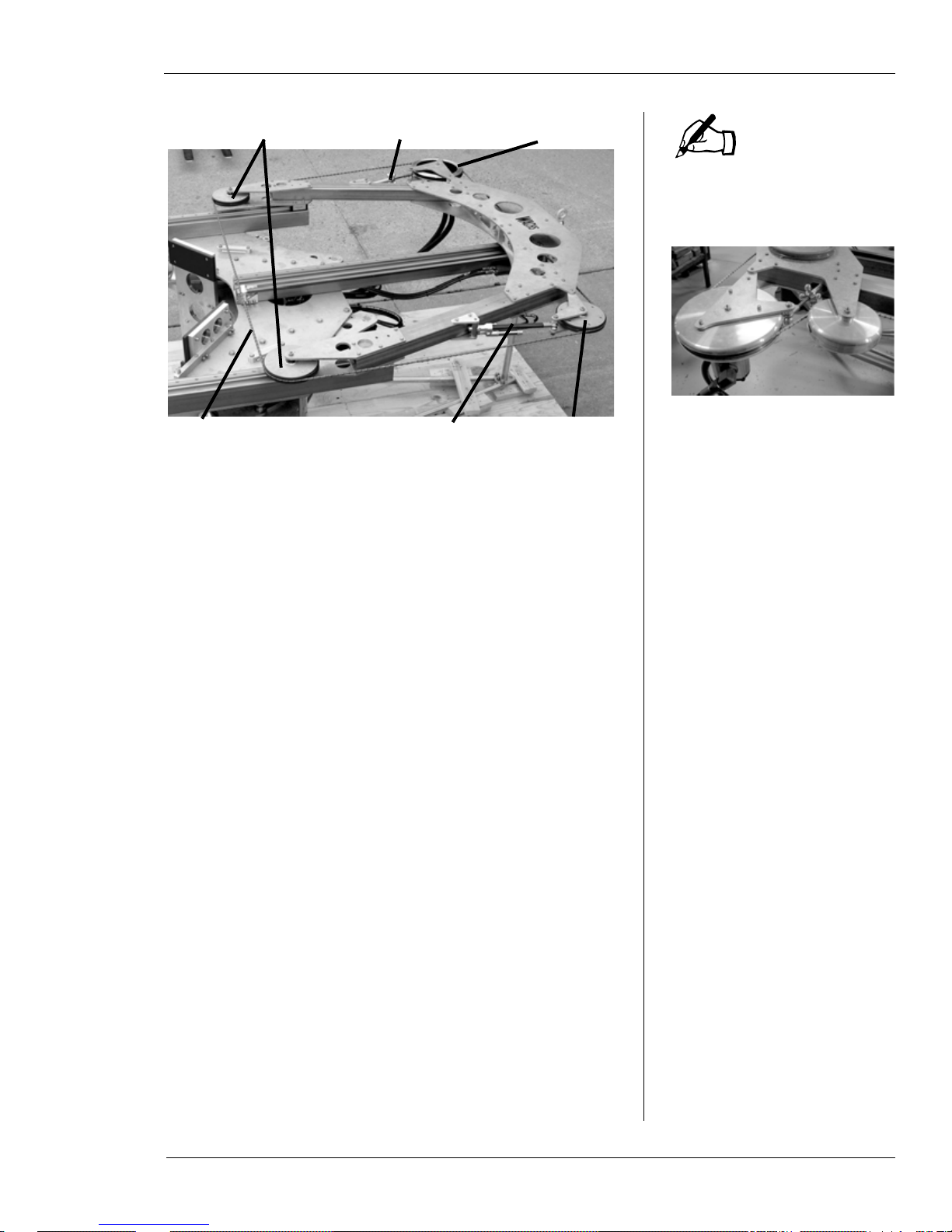
Cutting Wire Drive System
The cutting wire drive system consists of four wheels
mounted on the bow of the machine. Figure 1-1 illustrates
the drive system components.
4 Part No. 10-010-MAN, Rev. 1-0310 E.H. Wachs
Chapter 1, About the Diamond Wire Saw: Equipment Description
NOTE
Drive wheel Idler wheel
Idler wheels Drive wheel
Tension wheelDiamond wire
Tensioning knob
Tension spring
Figure 1-1. The photo shows the cutting wire drive
system components.
The WS-8460 has an additional idler wheel next to the
drive wheel.
The drive wheel is operated by the hydraulic drive motor to
turn the wire around the cutting system loop. It is mounted
on a pivoting fixture used to adjust the tension of the wire.
The tension is set using a knob on the fixture, which also
positions the wheel for installing and removing the cutting
wire.
The tension wheel is on a pivoting, spring-loaded fixture
that maintains wire tension. The other two idler wheels are
fixed at the bottom of the bow where the cutting wire
engages the pipe.
The wire is a custom-made loop for the size of the saw.
Spare wires can be ordered from E.H. Wachs.
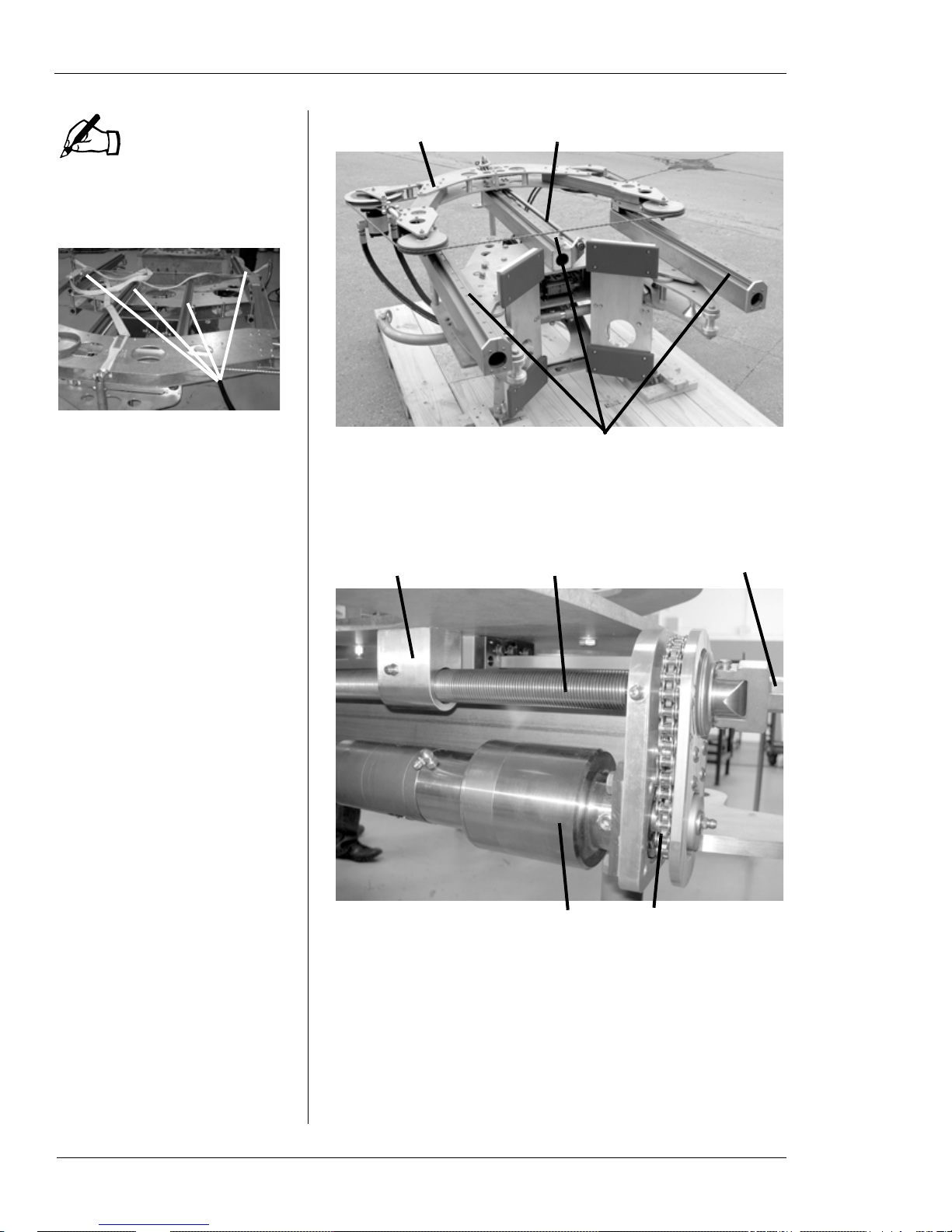
Feed System
A feed drive mechanism on the main frame of the machine
drives the bow and cutting system up and down to perform
the cut and retract the bow after cutting. The bow rides on
feed rails and is driven by a feed screw in the center of the
frame. Figure 1-2 and Figure 1-3 show the main feed system components.
E.H. Wachs Part No. 10-010-MAN, Rev. 1-0310 5
Diamond Wire Saw User’s Manual
NOTE
Feed rails
Feed rails
Saw bow
Feed screw
Feed block Feed screw
Feed motor Driv e chain
Manual feed nut
The WS-8460 has four feed
rails, as shown below. The
other models have three rails.
Figure 1-2. The saw bow moves on thr e e feed rails on
the frame. The feed screw along the center rail drives
the bow.
6 Part No. 10-010-MAN, Rev. 1-0310 E.H. Wachs
Figure 1-3. The feed system components are shown.
The feed block is attached to the saw bow.
The top of the feed screw has a drive nut to allow the feed to
be operated manually, and a clutch in the top coupling disengages the feed screw if the feed drive jams or reaches the
end of travel.
Chapter 1, About the Diamond Wire Saw: Equipment Description
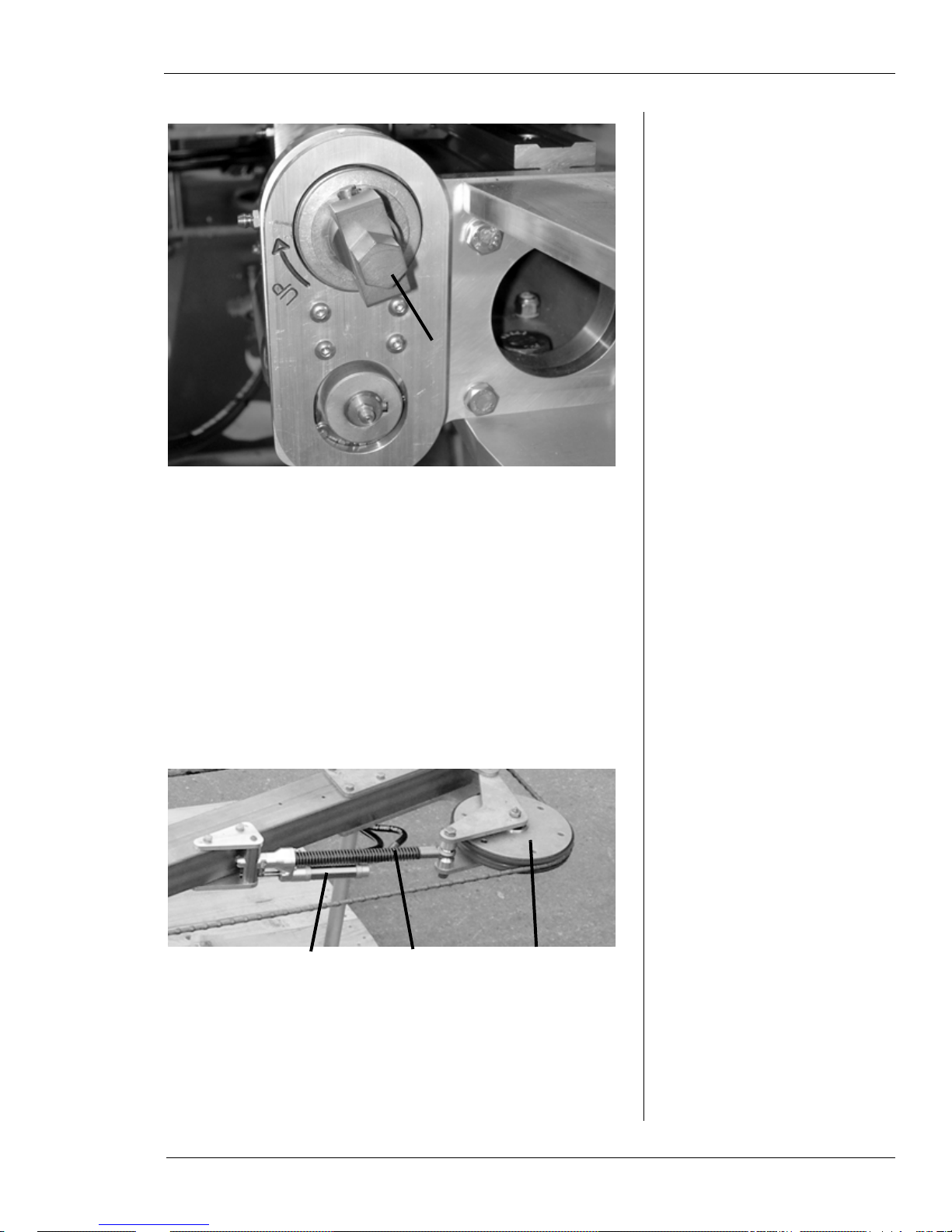
Manual
feed nut
Feed control actuator Tension wheelTension spring
Figure 1-4. Use the manual feed nut to move the saw
bow if it cannot be operated using hydraulic power.
T urn the nut clockwise to retract the bow away from
the workpiece.
The feed system has a self-adjusting speed control feature.
A hydraulic actuator on the tension wheel fixture measures
the deflection of the wire as it cuts. If the feed speed is too
fast, the increased wire deflection trips the actuator, which
slows down the feed rate. This allows the cutting action of
the wire to catch up. At maximum deflection of the wire, the
actuator will stop the feed motion for as long as necessary.
Figure 1-5. The actuator controls the feed rate by
measuring the deflection of the cutting wire.
E.H. Wachs Part No. 10-010-MAN, Rev. 1-0310 7
Diamond Wire Saw User’s Manual
Clamping
cylinder
Clamping
motion
Clamping arm
pivots to contact pipe
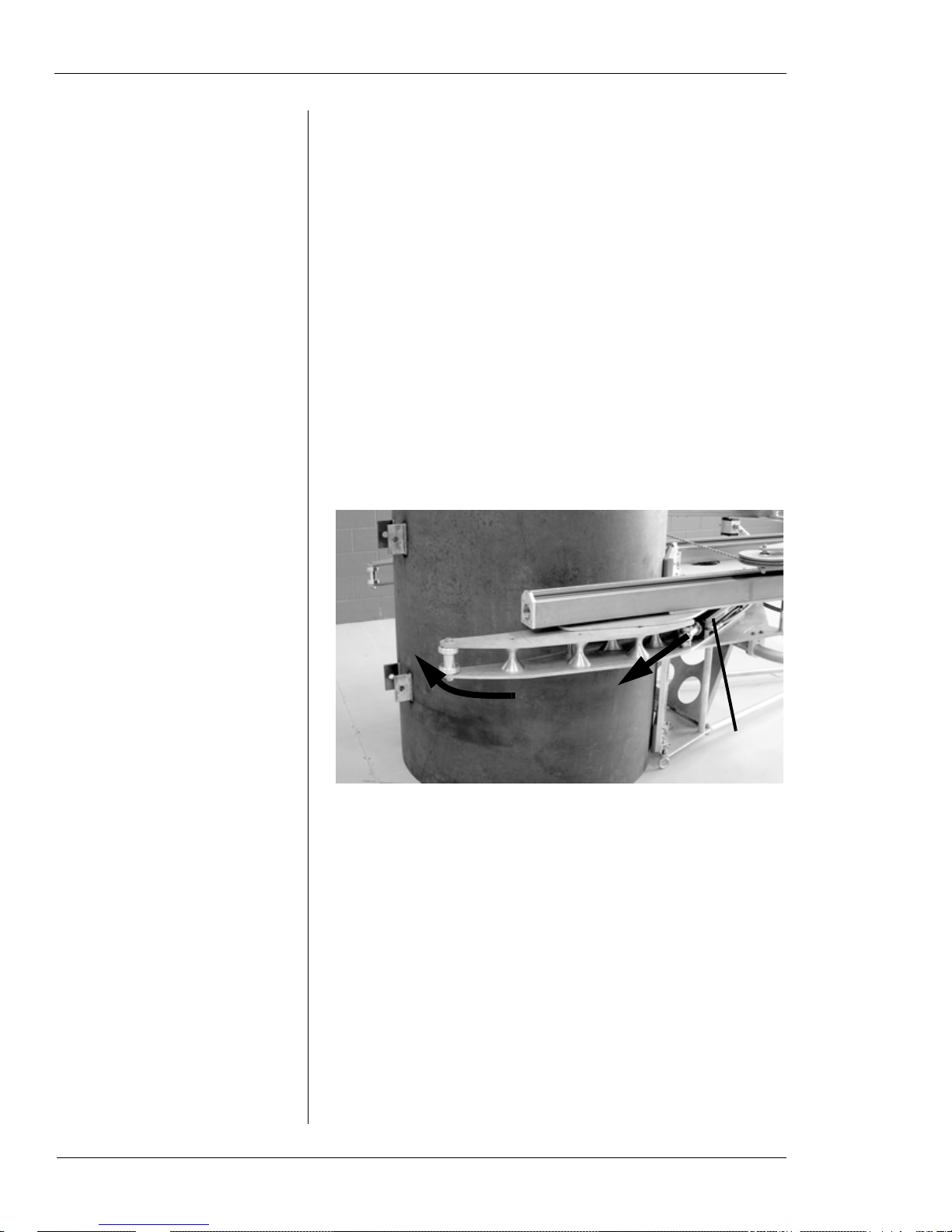
Clamping System
An adjustable clamping system allows you to configure the
machine for pipe sizes within each model’s range. The two
clamping arms are attached to the main frame with twopronged forked pins that are removable to reposition the
arms.
The clamping arms are engaged by hydraulic cylinders
mounted to the frame. When the cylinder rods are extended,
the clamps pivot inward to grip the underside of the pipe
and hold the machine securely to it. Figure 1-6 illustrates
the clamping operation.
See “Adjusting Clamp Arms for the Pipe Size” later in this
chapter for information on the clamp position settings for
each wire saw model.
8 Part No. 10-010-MAN, Rev. 1-0310 E.H. Wachs
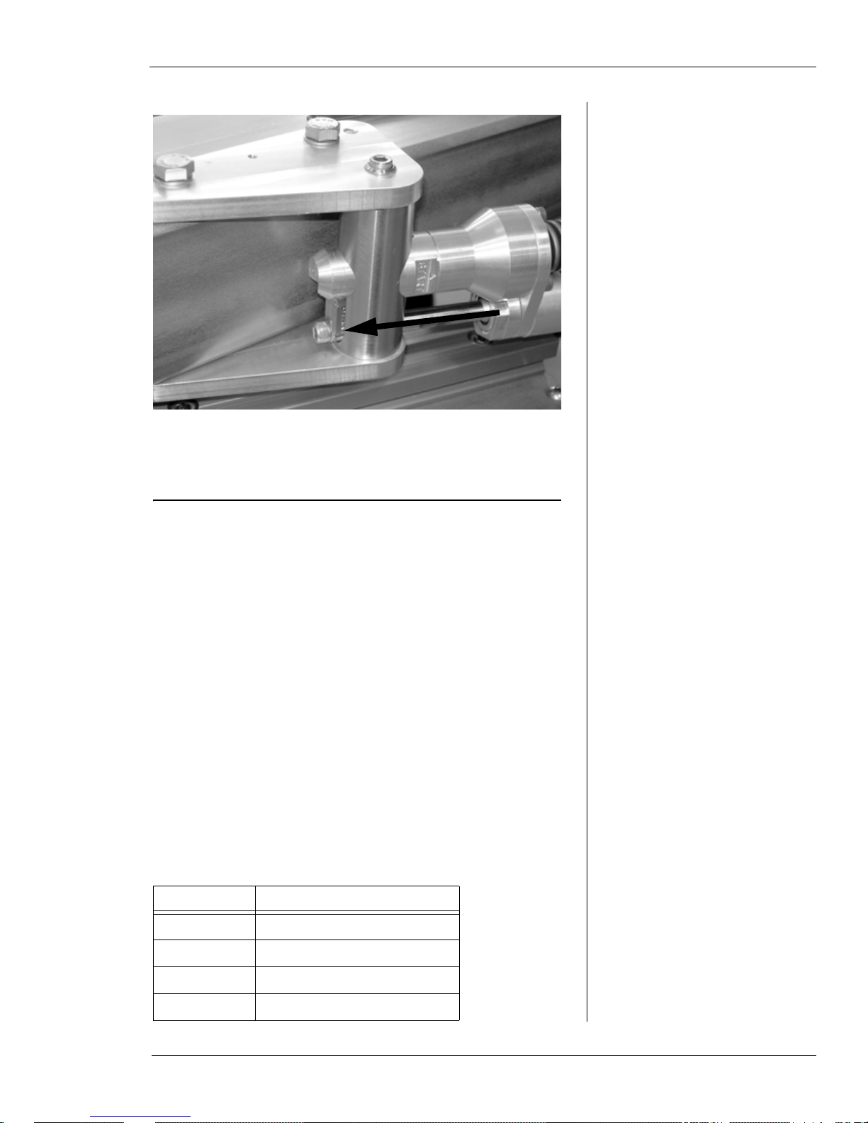
Figure 1-6. The photo shows the wire saw in position
for clamping on a test workpiece. When the hydraulic
cylinder is extended, the clamp arm pivots and closes
on the pipe. Both clamping arms operate together.
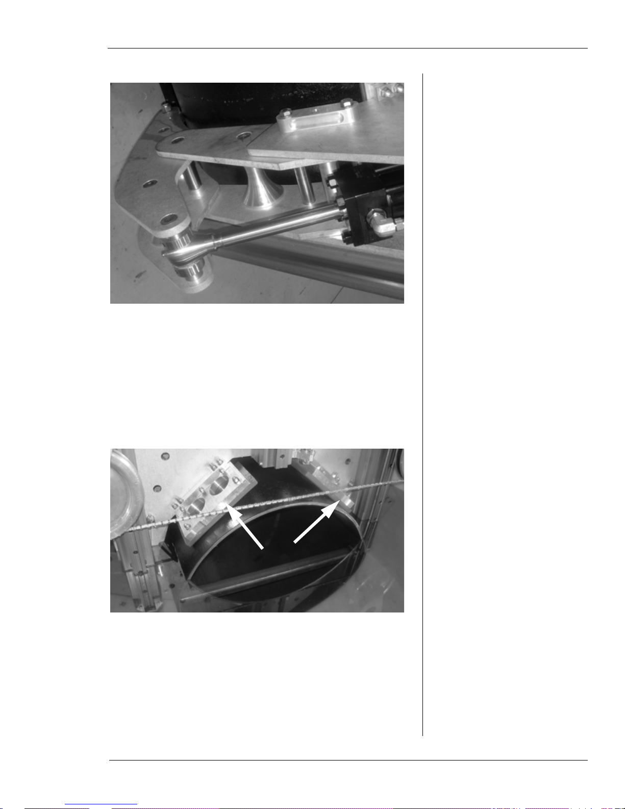
Chapter 1, About the Diamond Wire Saw: Equipment Description
Figure 1-7. The photo shows the clamping cylinder
extended and the clamp arm secured against the pipe.
The frame of the machine has clamp shoes attached that the
machine rests upon when installed on the pipe. These shoes
are made of a compressible composite material that deforms
slightly under pressure to create a secure, slip-free grip on
the pipe when the machine is clamped.
Figure 1-8. The front mounting shoes are shown.
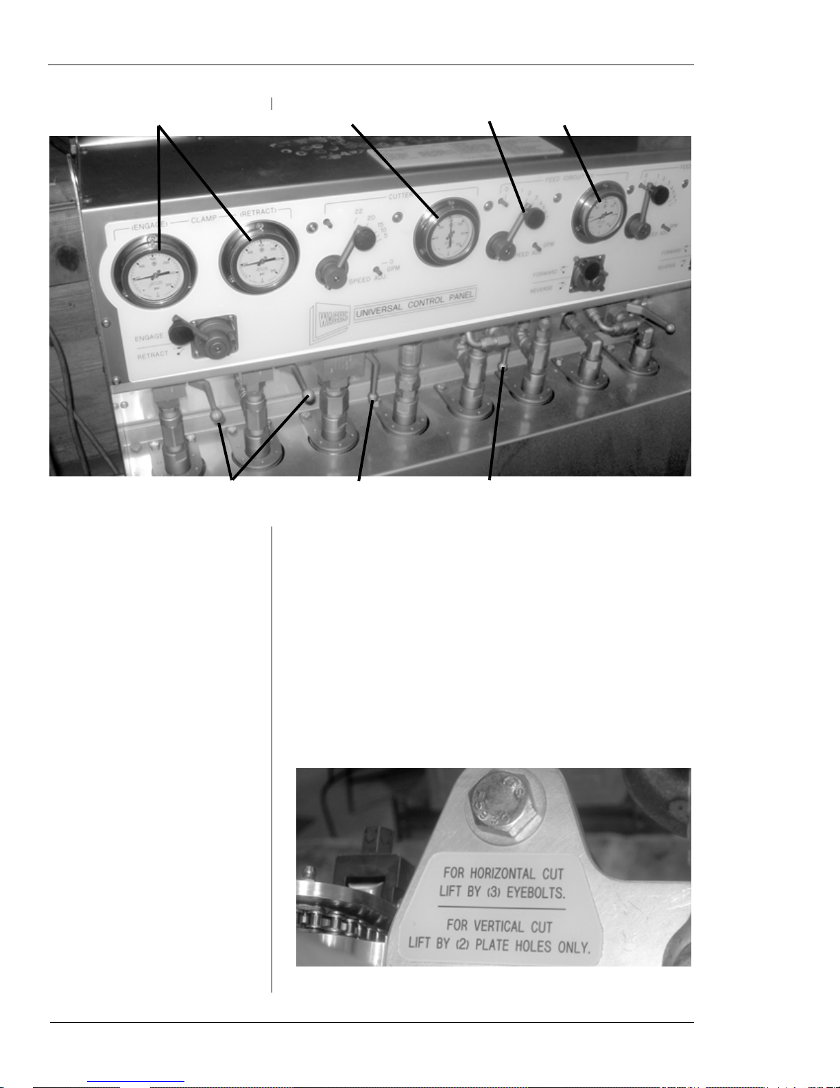
Topside Control Panel
Figure 1-9 illustrates the controls used to operate the subsea
wire saw. Chapter 3 includes detailed instructions.
E.H. Wachs Part No. 10-010-MAN, Rev. 1-0310 9
Diamond Wire Saw User’s Manual
Clamp pressure gauges
Clamp
direction
Cutter
speed
Cutter pressure gauge
Feed speed Feed pressure gauge
Feed
direction
Clamping flow levers (engage
both at once—shown closed
under pressure)
Feed flow lever
(shown open)
Cutter flow lever
(shown open)
Rigging the Machine
A rigging instruction label is attached to the top of the
machine frame on WS-164 through WS-5230 models. See
the end of this section for information on rigging the WS8460 model.
Figure 1-9. The photo shows the controls on the topside control unit. (The fourth cir cuit, to the far right, is
not used with the subsea wire saw.)
10 Part No. 10-010-MAN, Rev. 1-0310 E.H. Wachs
Figure 1-10. The rigging label is on top of the frame.
Chapter 1, About the Diamond Wire Saw: Equipment Description
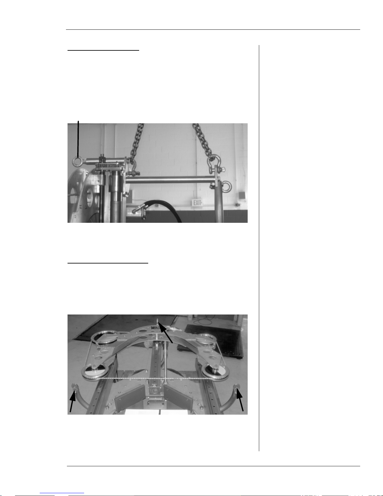
IMPORTANT: Do not attach to this hook
when lifting the machine vertically!
Lifting for Vertical Cut
Attach the machine to the lifting device using chains on the
top lift hooks. Tip the machine up to a vertical position, then
pick it up. Make sure the chains are the appropriate length to
hold the machine reasonably straight.
Figure 1-11. To position the machine vertically on the
pipe, attach to the two top lift hooks.
Lifting for Horizontal Cut
With the machine positio ned horizontal on the floor or deck,
attach a lift to the two hooks on the lift bar and the front
hook on top of the frame.
Figure 1-12. To position the machine horizontally on
the pipe, attach to the two lift bar hooks and the front
hook on the top.
E.H. Wachs Part No. 10-010-MAN, Rev. 1-0310 11
Diamond Wire Saw User’s Manual
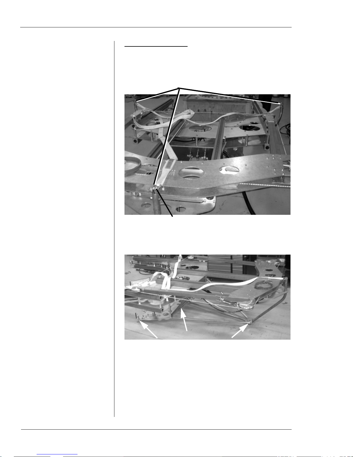
Lift vertically from this point only
Lift horizontally from these three points
Rigging the WS-8460
You can lift the WS-8460 saw vertically, or in either horizontal orientation. See the following figures for lift points.
Figure 1-13. Use the lift points indicated to lift the
machine horizontally or vertically.
Figure 1-14. To lift the machine horizontally from the
other side, use the three points indicated in the photo
(third point is out of view under frame).
Storing the Machine
Store the machine sitting horizontal with the front of it (the
side with the Wachs logo) facing up. For long-term storage,
12 Part No. 10-010-MAN, Rev. 1-0310 E.H. Wachs

Chapter 1, About the Diamond Wire Saw: Operating Envelope
clean and dry the machine thoroughly, then cover it with a
waterproof cover.
You can leave the wire installed on the machine during storage. Keep normal tension on the wire to hold it in place.
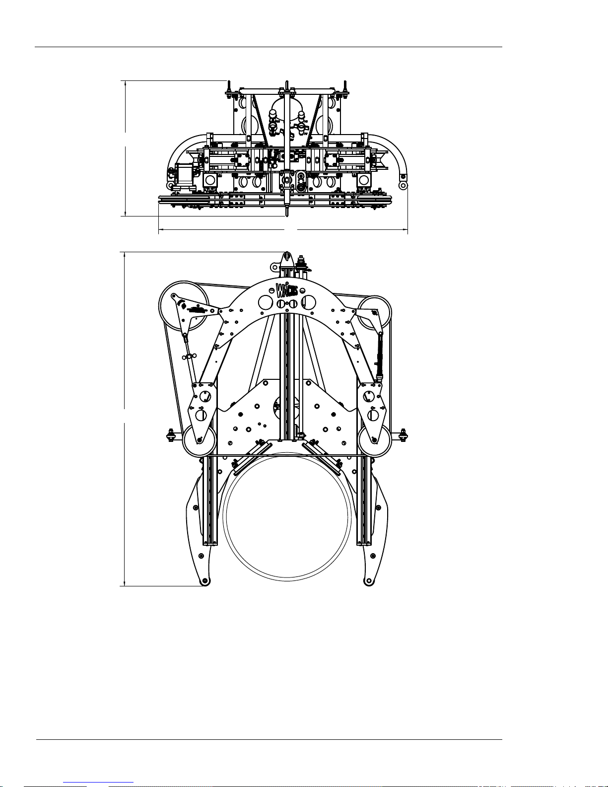
OPERATING ENVELOPE
The table below and the drawing on the next page describe
the operating envelope for all four diamond wire saw models. The “DIM” column in the table refers to the labeled
dimensions on the drawing. “Stroke” is the feed distance of
the saw bow.
Table 2: Operating Envelope Dimensions
Model DIM Inches MM
WS-164
WS-3012
WS-3616
WS-5230
A 48.5 1232
B28.0711
C 63.8 1621
Stroke 22.9 582
A 63.8 1621
B 34.9 886
C 82.6 2098
Stroke 39.0 991
A 69.6 1768
B 38.0 965
C 93.5 2375
Stroke 43.9 1115
A 87.4 2220
B 48.9 1242
C 131.0 3327
Stroke 61.9 1572
WS-8460
Stroke 97.8 2484
E.H. Wachs Part No. 10-010-MAN, Rev. 1-0310 13
A 119.0 3023
B46.51181
C 205.25 5213
Diamond Wire Saw User’s Manual
A
B
C
14 Part No. 10-010-MAN, Rev. 1-0310 E.H. Wachs

Chapter 2
Safety
The E.H. Wachs Company takes great pride in designing
and manufacturing safe, high-quality products. We make
user safety a top priority in the design of all our products.
Chapter 2, Safety
In This Chapter
OPERATOR SAFETY
SAFETY LABELS
Read this chapter carefully before operating the subsea wire
saw. It contains important safety instructions and recommendations.
OPERATOR SAFETY
WARNING: The cutting wire spins at very high speed. If
the wire breaks, segments of the wire can fragment and be
thrown from the machine at dangerous speeds. When operating the machine topside, stay a safe distance from the
machine, or behind a protective barrier. Divers should stay
a safe distance from the machine when it is running. Seri-
ous injury or death could result from contact with the
wire or as a result of the wire breaking.
Follow these guidelines for safe operation of the equipment.
• READ THE OPERATING MANUAL. Make sure
you understand all setup and operating instructions
before you begin.
• INSPECT MACHINE AND ACCESSORIES.
Before starting the machine, look for loose bolts or
nuts, leaking lubricant, rusted components, and any
other physical conditions that may affect operation.
Look for this symbol throughout the
manual. It indicates
a personal injury
hazard.
E.H. Wachs Part No. 10-010-MAN, Rev. 1-0310 15
Diamond Wire Saw User’s Manual
Properly maintaining the machine can greatly decrease
the chances for injury.
• ALWAYS READ PLACARDS AND LABELS. Make
sure all placards, labels, and stickers are clearly legible
and in good condition. You can purchase replacement
labels from E.H. Wachs Company.
• KEEP CLEAR OF MOVING PARTS. Keep hands,
arms, and fingers clear of all rotating or moving parts.
Always turn machine off before doing any adjustments
or service.
• SECURE LOOSE CLOTHING AND JEWELRY.
Secure or remove loose-fitting clothing and jewelry , and
securely bind long hair, to prevent them from getting
caught in moving parts of the machine.
• KEEP WORK AREA CLEAR. Keep all clutter and
nonessential materials out of the work area. Only people
directly involved with the work being performed should
have access to the area.
Safety Symbols
This icon is displayed with any safety alert that indicates a
personal injury hazard.
WARNING
This safety alert indicates a potentially hazardous situation
that, if not avoided, could result in death or serious injury.
CAUTION
This safety alert, with the personal injury hazard symbol,
indicates a potentially hazardous situation that, if not
avoided, could result in minor or moderate injury.
16 Part No. 10-010-MAN, Rev. 1-0310 E.H. Wachs
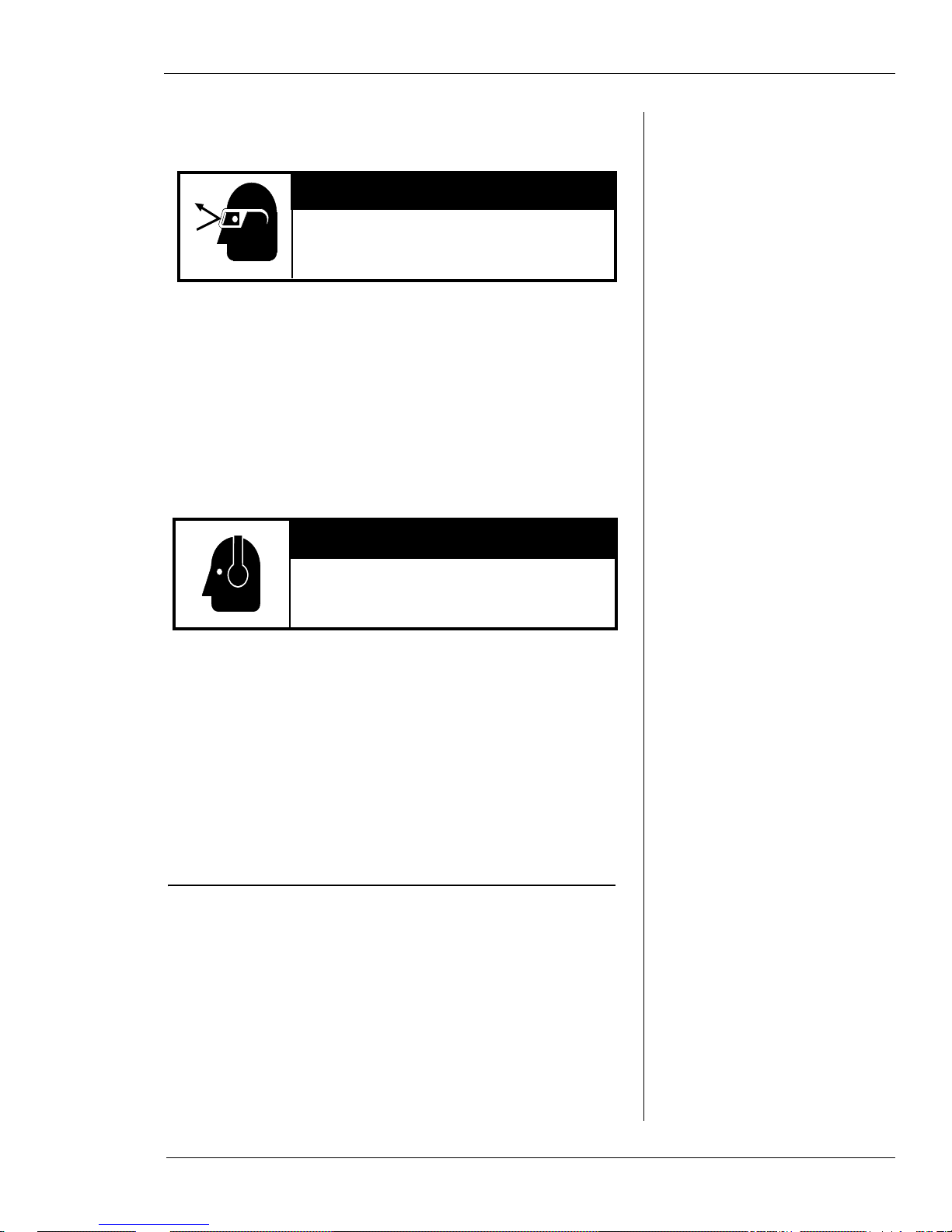
Protective Equipment Requirements
Always wear impact resistant eye protection while operating or working near
this equipment.
WARNING
CAUTION
Personal hearing protection is recommended when operating or working near
this tool.
For additional information on eye and face protection, refer
to Federal OSHA regulations, 29 Code of Federal Regulations, Section 1910.133., Eye and Face Protection and
American National Standards Institute, ANSI Z87.1, Occupational and Educational Eye and Face Protection. Z87.1 is
available from the American National Standards Institute,
Inc., 1430 Broadway, New York, NY 10018.
Chapter 2, Safety: Safety Labels
Hearing protectors are required in high noise areas, 85 dBA
or greater . The operation of other tools and equipment in the
area, reflective surfaces, process noises, and resonant structures can increase the noise level in the area. For additional
information on hearing protection, refer to Federal OSHA
regulations, 29 Code of Federal Regulations, Section
1910.95, Occupational Noise Exposure and ANSI S12.6
Hearing Protectors.
SAFETY LABELS
There is no safety labeling on the subsea wire saw.
E.H. Wachs Part No. 10-010-MAN, Rev. 1-0310 17

Diamond Wire Saw User’s Manual
18 Part No. 10-010-MAN, Rev. 1-0310 E.H. Wachs

Chapter 3
Operating
Instructions
TENSIONING THE CUTTING WIRE
You should have the wire installed according to the maintenance instructions in Chapter 4.
At the tension wheel fixture, check the start lines on
1.
the feed control actuator. When there is no tension on
the wire, the actuator rod will be retracted and the
start lines will be offset.
Chapter 3, Operating Instructions
In This Chapter
TENSIONING THE CUTTING
IRE
W
ADJUSTING CLAMP ARMS FOR
THE PIPE SIZE
CONNECTING THE HYDRAULIC
OSES
H
MOUNTING THE MACHINE ON
THE PIPE
PERFORMING THE CUT
REMOVING THE MACHINE
Figure 3-1. With no tension on the wire, the feed
actuator start lines will be offset.
E.H. Wachs Part No. 10-010-MAN, Rev. 1-0310 19
Diamond Wire Saw User’s Manual
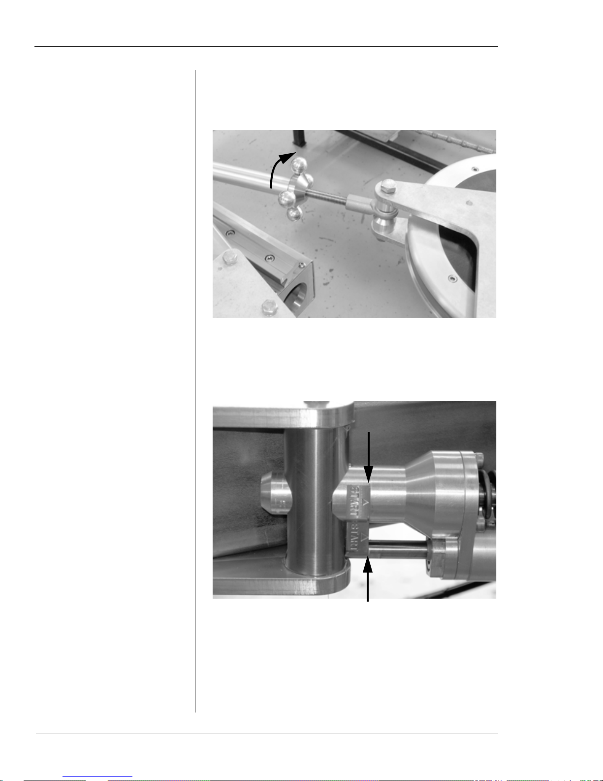
Tighten the drive wheel tensioning knob, as shown in
2.
Figure 3-2, until you can see the line on the springloaded driver wheel, Figure 3-3.
Figure 3-2. Turn the tension knob on the drive wheel
fixture to incr ease the tension on the wire. (Depending
on the exact length of the wire, about 3-4” of the scr ew
will be visible when the tension is set correctly.)
Figure 3-3. When the wire is properly tensioned, the
start lines will be lined up together.
20 Part No. 10-010-MAN, Rev. 1-0310 E.H. Wachs
You should be able to deflect the wire fairly easily by
3.
pushing it up between the idler wheels. Push it in far
enough to compress the tension spring, and make sure
the actuator rod extends into the slot in the shaft.
Chapter 3, Operating Instructions: Adjusting Clamp Arms for the Pipe Size
Figure 3-4. When you push the wire to deflect it, the
actuator rod will extend.
ADJUSTING CLAMP ARMS FOR THE PIPE SIZE
The clamp arms are attached to the main frame using forked
pins that go through two holes in the frame. Multiple sets of
holes allow the arms to be mounted in various positions.
The hole pairs for each position are stamped with the size of
the largest pipe for that position. Refer to the following sections for the pipe size settings for each saw model.
WS-164 Pipe Size Settings
Table 1 describes the pipe size settings for the WS-164
model.
Table 1: Pipe Size Ranges for Clamping
Arm Positions—WS-164
Size Stamp Pipe Diameter Range
7 4” to 7” (102-178 mm)
10 7” to 10” (178-254 mm)
13 10” to 13” (254-330 mm)
16 13” to 16” (330-406 mm)
E.H. Wachs Part No. 10-010-MAN, Rev. 1-0310 21
Diamond Wire Saw User’s Manual
WS-3012 Pipe Size Settings
T able 2 and Figure 3-5 describe the pipe size settings for the
WS-3012 model.
Table 2: Pipe Size Ranges for Clamping
Arm Positions—WS-3012
Size Stamp Pipe Diameter Range
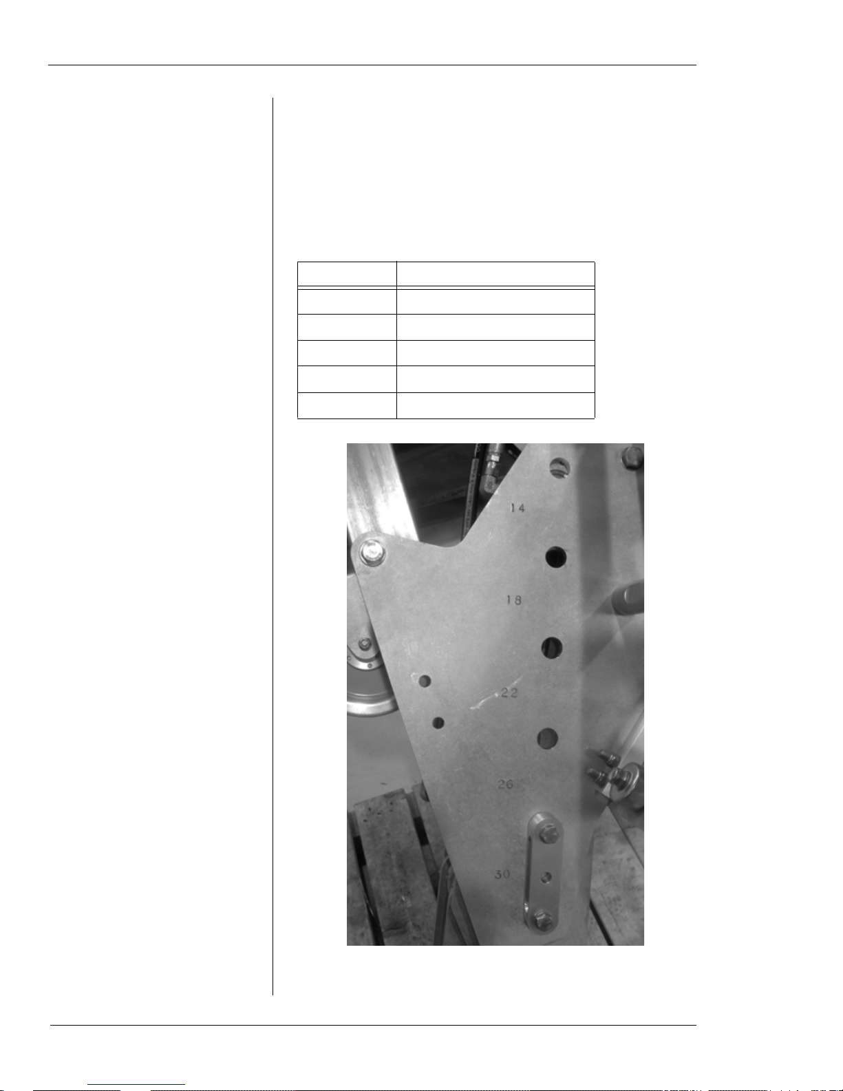
14 12” to 14” (305-356 mm)
18 14” to 18” (356-457 mm)
22 18” to 22” (457-559 mm)
26 22” to 26” (559-660 mm)
30 26” to 30” (660-762 mm)
22 Part No. 10-010-MAN, Rev. 1-0310 E.H. Wachs
Figure 3-5. The photo shows the size stamps on the
WS-3012 model. The pin is in the 26-30” position.
Chapter 3, Operating Instructions: Adjusting Clamp Arms for the Pipe Size
WS-3616 Pipe Size Settings
T able 3 and Figure 3-6 describe the pipe size settings for the
WS-3616 model.
Table 3: Pipe Size Ranges for Clamping
Arm Positions—WS-3616
Size Stamp Pipe Diameter Range
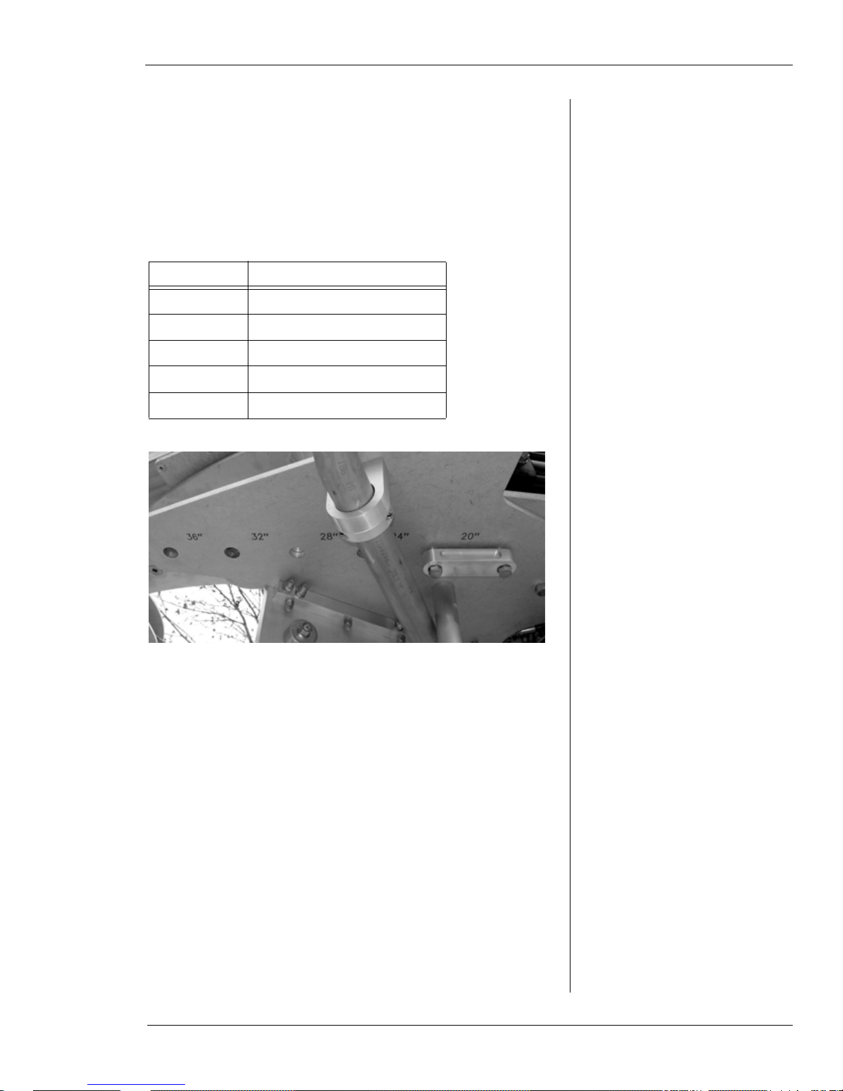
20 16” to 20” (406-508 mm)
24 20” to 24” (508-610 mm)
28 24” to 28” (610-711 mm)
32 28” to 32” (711-813 mm)
36 32” to 36” (813-914 mm)
Figure 3-6. The photo shows the size stamps on the
WS-3616 model. The pin is in the 16-20” position.
E.H. Wachs Part No. 10-010-MAN, Rev. 1-0310 23
Diamond Wire Saw User’s Manual
WS-5230 Pipe Size Settings
T able 4 and Figure 3-7 describe the pipe size settings for the
WS-5230 model.
Table 4: Pipe Size Ranges for Clamping
Arm Positions—WS-5230
Size Stamp Pipe Diameter Range
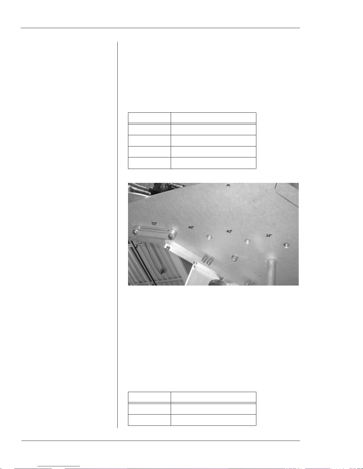
34 30” to 34” (762-864 mm)
40 34” to 40” (864-1016 mm)
46 40” to 46” (1016-1168 mm)
52 46” to 52” (1168-1321 mm)
24 Part No. 10-010-MAN, Rev. 1-0310 E.H. Wachs
Figure 3-7. The photo shows the size stamps on the
WS-5230 model. The pin is in the 46-52” position.
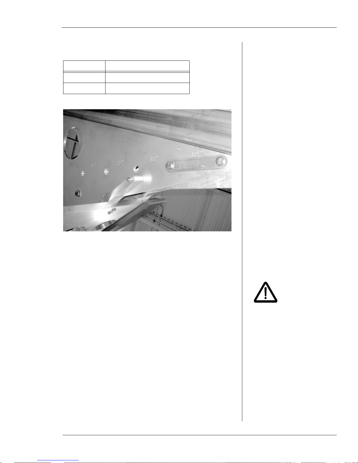
WS-8460 Pipe Size Settings
T able 5 and Figure 3-8 describe the pipe size settings for the
WS-8460 model.
Table 5: Pipe Size Ranges for Clamping
Arm Positions—WS-8460
Size Stamp Pipe Diameter Range
66 60” to 66” (152 4-1676 mm)
72 66” to 72” (167 6-1829 mm)
Chapter 3, Operating Instructions: Adjusting Clamp Arms for the Pipe Size
WARNING
Table 5: Pipe Size Ranges for Clamping
Arm Positions—WS-8460
Size Stamp Pipe Diameter Range
78 72” to 78” (1829 -1981 mm)
84 78” to 84” (1981 -2134 mm)
Figure 3-8. The photo shows the size stamps on the
WS-8460 model. The pin is in the 78-84” position.
Positioning the Clamp Arms
Make sure the saw is sitting horizontally on a level surface
before you adjust the clamp arms.
Remove the spring clips from both pin ends of the
1.
forked pin, then pull the forked pin out of the frame.
Do not attempt to change the
clamp arm positions while the
saw is in a vertical position.
The clamp arms may fall
when the pins are removed,
resulting in personal injury
and equipment damage.
E.H. Wachs Part No. 10-010-MAN, Rev. 1-0310 25
 Loading...