

Wachs Trav-L-Cutter HE, Trav-L-Cutter E User Manual
E.H. Wachs
600 Knightsbridge Parkway
Lincolnshire, IL 60069
www.ehwachs.com
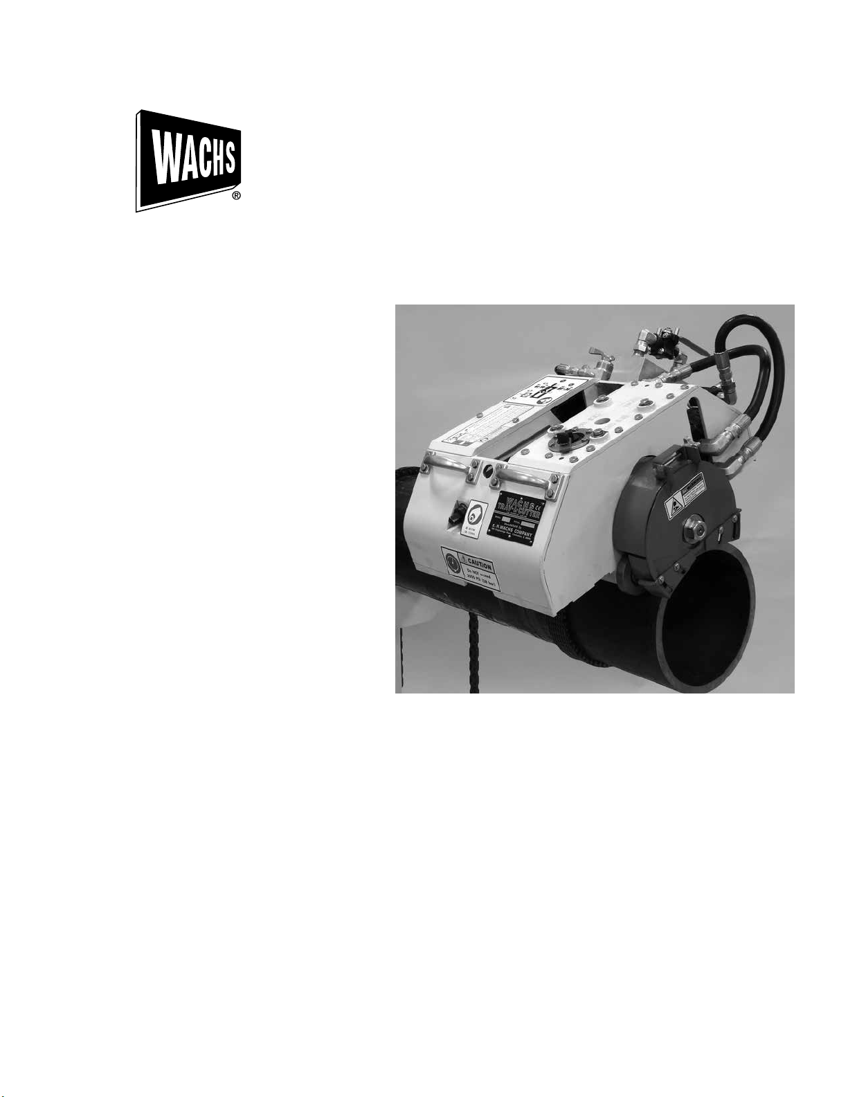
TRAV-L-CUTTER
MODEL E & H/E
STANDARD & ATMOSPHERIC
02-000-01,-02,-03,-04
E.H. Wachs Part No. 02-MAN-01
Rev. A, March 2014
Copyright © 2014 E.H. Wachs. All rights reserved.
This manual may not be reproduced in whole or in part
without the written consent of E.H. Wachs.

EU DECLARATION OF CONFORMITY
WITH
COUNCIL DIRECTIVE 2006/42/EC
Issue Details: DATE:
1/1/2011
Directives: Machinery Safety Directive 2006/42/EC
Conforming Machinery:
Model Number: 02-000-01, 02-000-02
Serial Number:
Manufacturer: E.H. Wachs
Responsible Representative: Orbitalum Tools GmbH
Harmonised Standards &
Other Technical
Standards/Specications
Applied or Referenced:
Provisions with which
Conformity is Declared:
We hereby certify that the machinery descrived above conforms to the provisions of
Council Directive 2006/42/EC on the approximation of the laws of the Member States
relating to the safety of machinery.
Signed:
Trav-L-Cutter:
600 Knightsbridge Parkway
Lincolnshire
IL 60069
USA
Josef-Schüttler-Str. 17, 78224 Singen
Germany
Tel. +49 (0) 7731 - 792 872
Fax +49 (0) 7731 - 792 566
EN ISO 12100-1:2003 + A1:2009
EN ISO 12100-2:2003 + A1:2009
EN 60201-1:2006 (for electric machines)
EN ISO 13857:2008
EN 982:1996 + A1:2008 (E) (for hydrailic machines)
EN 983:1996 (for pneumatic machines)
EN 13732-1:2006
EN ISO 14121-1:2007
EN ISO 13850:2008 (for pneumatic machines)
Essential Health and Safety Requirements of Annex 1 of the
Machinery Directive
Place:
E.H.Wachs, Lincolnshire, IL USA
Signatory: Pete Mullally
Quality Manager
E.H. Wachs

Table of Contents
Table of Contents
Chapter 1: Introduction to the Equipment .........................................1
Purpose of This Manual .........................................................1
How to Use The Manual .........................................................1
Symbols and Warnings ..........................................................2
Manual Updates and Revision Tracking .............................................3
Equipment Description ..........................................................3
Compact Design, Easy Set-up ...............................................3
Standard Weld Prep Capability ..............................................3
Grooved, Mechanical Joint Preparation........................................3
Offshore or Pipe Line Maintenance ...........................................3
Corrosion Resistant .......................................................4
Operates Anywhere .......................................................4
Safe, Cold Cutting ........................................................4
Fast, Reliable ............................................................4
Chapter 2: Safety ..............................................................5
Safe Operating Guidelines. . . . . . . . . . . . . . . . . . . . . . . . . . . . . . . . . . . . . . . . . . . . . . . . . . . . . . . . 5
Safe Operating Environment ...................................................6
Operating and Maintenance Safety ..............................................6
Safety Alerts in This Manual ...................................................6
Protective Equipment Requirements .............................................7
Protective Clothing .......................................................7
Eye Protection ...........................................................7
Hearing Protection........................................................7
Chapter 3: Machine Specications ...............................................9
Chapter 4: Setup and Operating Procedures ......................................15
Wheel Settings ...............................................................15
Chain Lengths ................................................................16
Wheel Settings and Chain Length .................................................17
Chain Length Calculations ...................................................17
Machine Installation ...........................................................18
Operating the Machine .........................................................20
Special Instructions for Assembling 2” Wide Drive Chain ...........................21
Operating Hints .........................................................22
Chapter 5: Maintenance .......................................................23
Lubrication Instructions ........................................................23
E.H. Wachs Part No. 02-MAN-01, Rev. A i

Trav-L-Cutter
Chapter 6: Consumable Select Chart ............................................25
Data on Cutter Size ............................................................25
Cutters ......................................................................27
Chapter 7: Troubleshooting Problems ............................................29
Chapter 8: Parts Lists & Exploded View Drawings .................................31
ii Part No. 02-MAN-01, Rev. A E.H. Wachs

Chapter 1, Introduction to the Equipment
Chapter 1
Introduction to the Equipment
PurPose of This Manual
This manual explains how to operate and maintain the Trav-L-Cutter. It includes instructions for
set-up, operation, and maintenance. It also contains parts lists and diagrams, and troubleshooting
instructions to help you order replacement parts and perform user-service able repairs.
how To use The Manual
This manual is organized to help you quickly nd the infor mation you need. Each chapter de-
scribes a specic topic on using or maintaining your equipment.
Use these instructions to operate and maintain the equipment.
E.H. Wachs Part No. 02-MAN-01, Rev. A 1
Trav-L-Cutter
syMbols and warnings
The following symbols are used throughout this manual to indicate special notes and warnings.
They appear in the out side column of the page, next to the section they refer to. Make sure you
understand what each symbol means, and follow all instructions for cautions and warnings.
This is the safety alert symbol. It is used to alert you to potential personal
injury hazards. Obey all safety messages that follow this symbol to avoid
possible injury or death.
WARNING
A WARNING alert with the safety alert symbol indicates a potentially hazardous situa tion that could
result in seri ous injury or death.
CAUTION
A CAUTION alert with the safety alert symbol indicates a potentially hazardous situa tion that could result
in minor or moderate injury.
A CAUTION alert with the damage alert symbol indicates a situation that will result in
damage to the equipment.
This is the equipment damage alert symbol. It is used to alert you to poten tial
equipment damage situations. Obey all messages that follow this sym bol to
avoid damaging the equipment or workpiece on which it is operating.
IMPORTANT
An IMPORTANT alert with the damage alert symbol indi cates a situation that may result in
damage to the equipment.
NOTE
This symbol indicates a user note. Notes provide additional information to
supple ment the instructions, or tips for easier operation.
2 Part No. 02-MAN-01, Rev. A E.H. Wachs

Chapter 1, Introduction to the Equipment: Manual Updates and Revision Tracking
Manual uPdaTes and revision Tracking
Occasionally, we will update manuals with improved opera tion or maintenance procedures, or
with corrections if nec essary. When a manual is revised, we will update the revision history on the
title page.
Current versions of E.H. Wachs Company manuals are also available in PDF for mat. You can
request an electronic copy of this manual by emailing customer service at sales@ehwachs.com.
You may have factory service or upgrades performed on the equipment. If this service changes any
technical data or operation and maintenance procedures, we will include a revised manual when
we return the equipment to you.
equiPMenT descriPTion
Compact Design, Easy Set-up
Lightweight, low prole design needs only 10” to 12” of clearance and set up time is ten minutes or
less. Once the adjustable drive chain is pinned together and tensioned around the pipe the machine
is ready to operate.
Standard Weld Prep Capability
Weld preparation detail can be achieved from common 30º and 37-1/2º bevel on standard wall
carbon steel.
Grooved, Mechanical Joint Preparation
The Trav-L-Cutter can simultaneously cut off and groove pipe in one cut. Cutters are available for
Victaulic and other grooved coupling systems.
Offshore or Pipe Line Maintenance
The Wachs Hydraulic Trav-L-Cutter offers the inherent advantages of a completely sealed and
self-lubricating closed loop system. The Model HE is particularly suited to eld machining operations under the type of hostile conditions often found in pipe line maintenance and construction
such as dirt, sand and water. It is a portable pipe cutting machine that can be used conveniently on
offshore drilling rigs, pipe lines and on construction work in rivers and harbors.
E.H. Wachs Part No. 02-MAN-01, Rev. A 3

Trav-L-Cutter
Corrosion Resistant
Corrosion from constant exposure to salt water can be minimized with an accessory package that
includes extensive use of stainless steel fasteners, special bearings and seals and high zinc coating.
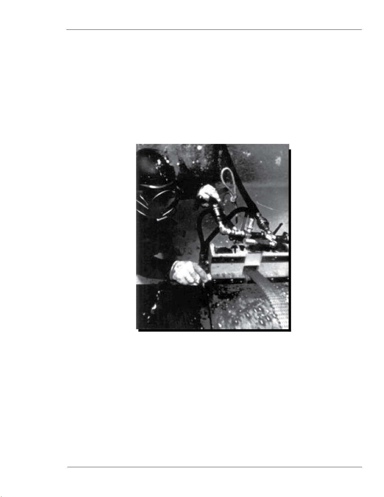
Operates Anywhere
With air or hydraulic power, the Trav-L-Cutter will operate on horizontal or vertical pipe, in the
eld or in the shop. It cuts and bevels in a mud lled ditch or under water, where it has been used in
chambers and free diving to depths of 600 feet.
Safe, Cold Cutting
The Trav-L-Cutter can be used in explosive conditions, onnatural gas, crude, product and fuel
lines. It has even been used to cut missile fuel cells.
Fast, Reliable
A standard wall pipe can be cut and beveled with a cutting speed of approximately 2 minutes per 1”
of pipe diameter. Cutting time varies for heavier walls and harder alloys. Due to its rugged con-
struction, it is not unusual to nd machines still operating after 10 or 20 years of severe service.
Included with your TRAV-L-CUTTER:
• Operating Manual and Isometric Parts List, Operating Tools, and spare Chain Connecting Pins.
• Basic Mounting Chain for 6” dia. pipe
• Steel Storage Case
• 6-ft. Hose Whip with oiler (air only)
4 Part No. 02-MAN-01, Rev. A E.H. Wachs

Chapter 2, Safety
Chapter 2
Safety
E.H. Wachs takes great pride in designing and manufactur ing safe, high-quality products. We
make user safety a top priority in the design of all our products.
Read this chapter carefully before operating the bridge slide. It contains important safety instructions and recom mendations.
FULL SAFETY INSTRUCTIONS AND GUIDELINES ARE IN THE MANUAL FOR
YOUR TRAV-L-CUTTER MACHINE. Make sure you read and understand these safety recom-
mendations and operating instructions before operating.
safe oPeraTing guidelines
Follow these guidelines for safe operation of all E.H. Wachs equipment.
Look for this sym bol throughout the manual. It indicates a personal injury
hazard.
• READ THE OPERATING MANUAL. Make sure you under stand all setup and operating instructions
before you begin. Keep this manual with the machine.
INSPECT MACHINE AND ACCESSORIES BEFORE USE. Before starting the machine, look for loose
•
bolts or nuts, leak ing lubricant, rusted components, and any other physi cal conditions that may
affect operation. Properly maintaining the machine can greatly decrease the chances for injury.
ALWAYS READ STICKERS AND LABELS. Make sure all labels and stickers are in place, clearly
•
legible, and in good condition. Refer to “Safety Labels” later in this chapter for label locations
on the machine. Replace any dam aged or missing safety labels; see the ordering informa tion at
the end of this manual.
KEEP CLEAR OF MOVING PARTS. Keep hands, arms, and ngers clear of all rotating or moving
•
parts. Always turn the machine off and disconnect the power source before doing any adjustments or service.
E.H. Wachs Part No. 02-MAN-01, Rev. A 5

Trav-L-Cutter
• SECURE LOOSE CLOTHING AND JEWELRY. Secure or remove loose-tting clothing and jewelry,
and securely bind long hair, to prevent them from getting caught in moving parts of the machine.
FOLLOW SAFE PROCEDURES FOR HANDLING LUBRICANTS. Refer to the manufacturer’s instruc-
•
tions and the Mate rial Safety Data Sheets.
Safe Operating Environment
• Do not use this equipment in a potentially explosive atmosphere. Fire or explosion could result,
with the risk of serious injury or death.
• Provide adequate lighting to use the equipment, in accordance with worksite or local regulations.
KEEP WORK AREA CLEAR. Keep all clutter and nonessen tial materials out of the work area. Only
•
people directly involved with the work being performed should have access to the area.
Operating and Maintenance Safety
• This equipment is to be operated and maintained only by qualied, trained personnel.
• Make sure the equipment is stable when attached to the workpiece for the operation. Ensuring
stability of the installed tool is the responsibility of the operator.
• Make sure the workpiece is supported adequately for installation of the equipment. This
includes supporting any workpiece “fall-off” section when severing the workpiece. Ensuring
support of the workpiece is the responsibility of the operator.
• Tooling on any cutting equipment—including lathe tools, saw blades, milling tools, etc.—may
get very hot. Do not touch tooling until you have made sure it is cool enough to handle.
• Wear gloves when removing or cleaning up chips and cutting debris. Chips can be very sharp
and cause cuts.
• Before performing any service on the equipment, dis connect the power source. Follow all
lock-out/tag-out procedures required at the worksite.
Safety Alerts in This Manual
The following alerts are used throughout this manual to indicate operator safety hazards. In all
cases, these alerts include a notice describing the hazard and the means to avoid or reduce risk.
Carefully read all safety alerts.
This icon is displayed with any safety alert that indicates a personal injury
hazard.
WARNING
This safety alert, with the personal injury hazard symbol, indicates a potentially hazardous
situation that, if not avoided, could result in death or serious injury.
6 Part No. 02-MAN-01, Rev. A E.H. Wachs

Chapter 2, Safety: Safe Operating Guidelines
CAUTION
This safety alert, with the personal injury hazard symbol, indicates a potentially hazardous
situation that, if not avoided, could result in minor or moderate injury.
Protective Equipment Requirements
Protective Clothing
Wear safety shoes when operating or servicing the equip ment. Serious injury could result from
dropping the machine or its components.
Do not wear gloves while operating the machine. Gloves can become entangled in moving parts,
resulting in serious injury. Gloves may be worn when setting up the machine or cleaning up after
the operation, but take them off when operating the machine.
NOTE
Gloves should be worn when cleaning up chips and other cutting debris. Chips can
be very sharp and can cause serious cuts. Do not wear gloves when the machine
is operating.
Eye Protection
Always wear impact-resistant eye protection while operat ing or working near this equipment.
For additional information on eye and face protection, refer to Federal OSHA regulations, 29 Code
of Federal Regula tions, Section 1910.133., Eye and Face Protection and American National
Standards Institute, ANSI Z87.1, Occu pational and Educational Eye and Face Protection.
Hearing Protection
This equipment can produce noise levels above 80 dB. Hearing protection is required when operat-
ing the equip ment. The operation of other tools and equipment in the area, reective surfaces,
process noises, and resonant struc tures can increase the noise level in the area.
For additional information on hearing protection, refer to Federal OSHA regulations, 29 Code of
Federal Regulations, Section 1910.95, Occupational Noise Exposure and ANSI S12.6 Hearing
Protectors.
E.H. Wachs Part No. 02-MAN-01, Rev. A 7

Trav-L-Cutter
8 Part No. 02-MAN-01, Rev. A E.H. Wachs
Chapter 3, About This Manual
Chapter 3
Machine Specications
Capacity:
6” through 72” (153 to 1829 mm) pipe, large diameter vessels. All schedules.
Cutter Drive:
Pneumatic: 4 H.P. Governed Air Motor coupled with worm gearbox
Hydraulic:
As above, with hydraulic motor.
Cutter Speed:
Pneumatic: 55 R.P.M. Internally adjustable from 35 to 55 R.P.M. for use on alloys that might
become work hardened. Hydraulic; Adjustable 0-60 R.P.M.
E.H. Wachs Part No. 02-MAN-01, Rev. A 9

Trav-L-Cutter
Feed:
Pneumatic: 3/4 H.P. Air Motor coupled through overload clutch, gearbox and chain reduction to
nal machine drive sprocket. Hydraulic: 4 H.P. Hydraulic Motor.
Feed Method: Positive, non-slip chain drive
Air Requirements: 100 cfm @ 90 psi (2,832 l/min @ 6.3 bar)
Hydraulic Requirements: 15 gpm @ 1500 psi. (57 l/min @ 106 bar)
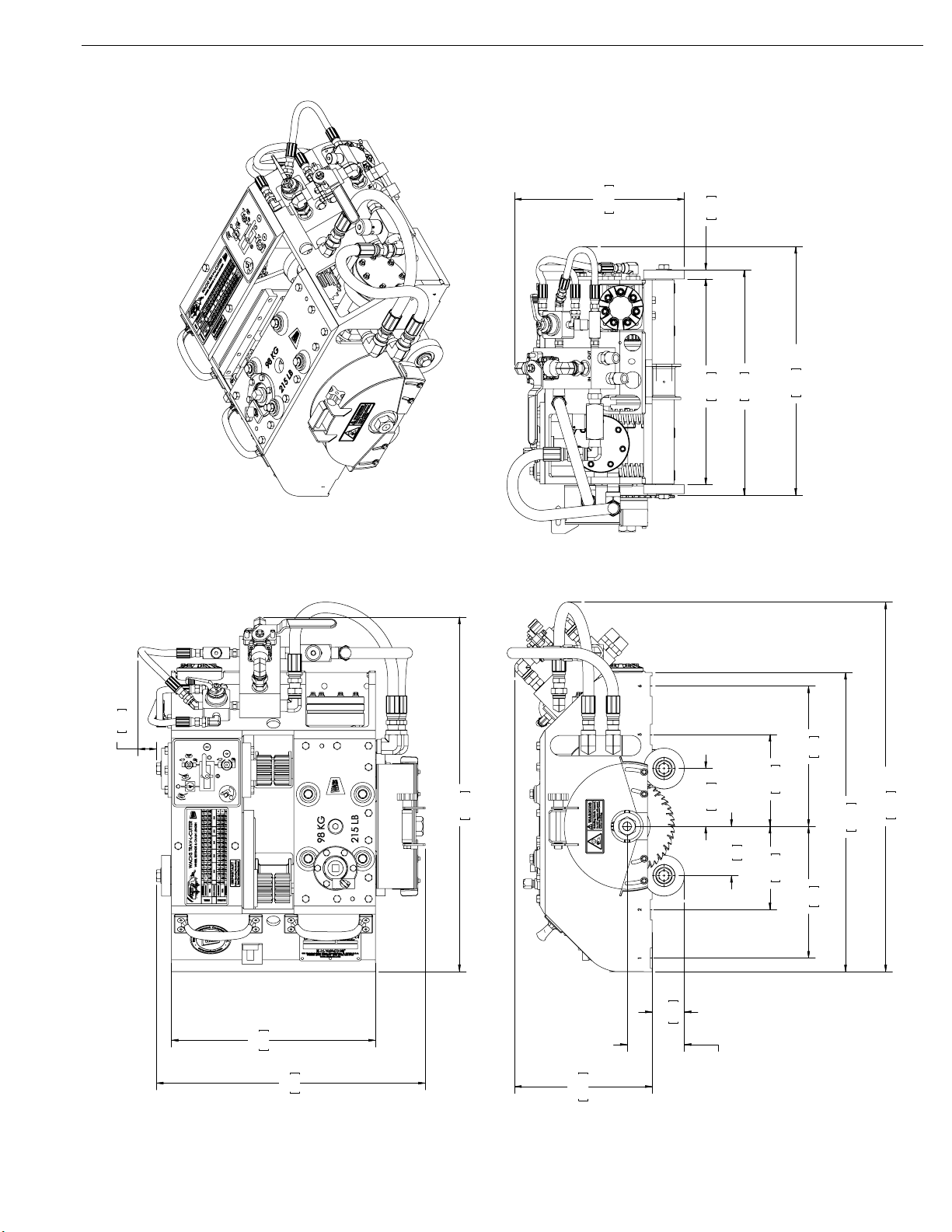
Clearance:
10” to 12” (254 to 305 mm) radial, depending on pipe diameter. 20” axial (508 mm)
Weight:
Operating - 215 lbs. (97.7 kgs)
Shipping-(typical) - 418 lbs. (190 kg)
Dimensions:
Length: 24” (61 cm)
Width: 20” (51 cm)
Height: 10-3/4” (28 cm)
Controls:
(Pneumatic and Hydraulic):
Cutter on-off, feed on-off, with interlock to prevent machine feed unless cutter is turning. Adjustable Feed Speed Control (Hydraulic Only) Flow Control Valves. Separate controls provide adjustable feed and cutter speed. Forward/Reverse Valve. Permits machine to be backed up.
Shipping and Storage Case:
41” x 25” x 18” (104 x 63.5 x 45.7 cm)
2
10.7 cu. ft. (0.53 m
)
Finish: Paint
Hose Assemblies (Hydraulic):
5/8” hose sets with quick couplers, in 45’ lengths
Hydraulic Power Sources (Model HE):
- Electric, Gasoline or Diesel Engine driven.
Gang of Cutters for Beveling Pipe
1 R.H. Bevel, 1 Slitting Saw, and 1 L.H. Bevel
10 Part No. 02-MAN-01, Rev. A E.H. Wachs
Chapter 3, About This Manual: Machine Specications
TYP
.66
16.8
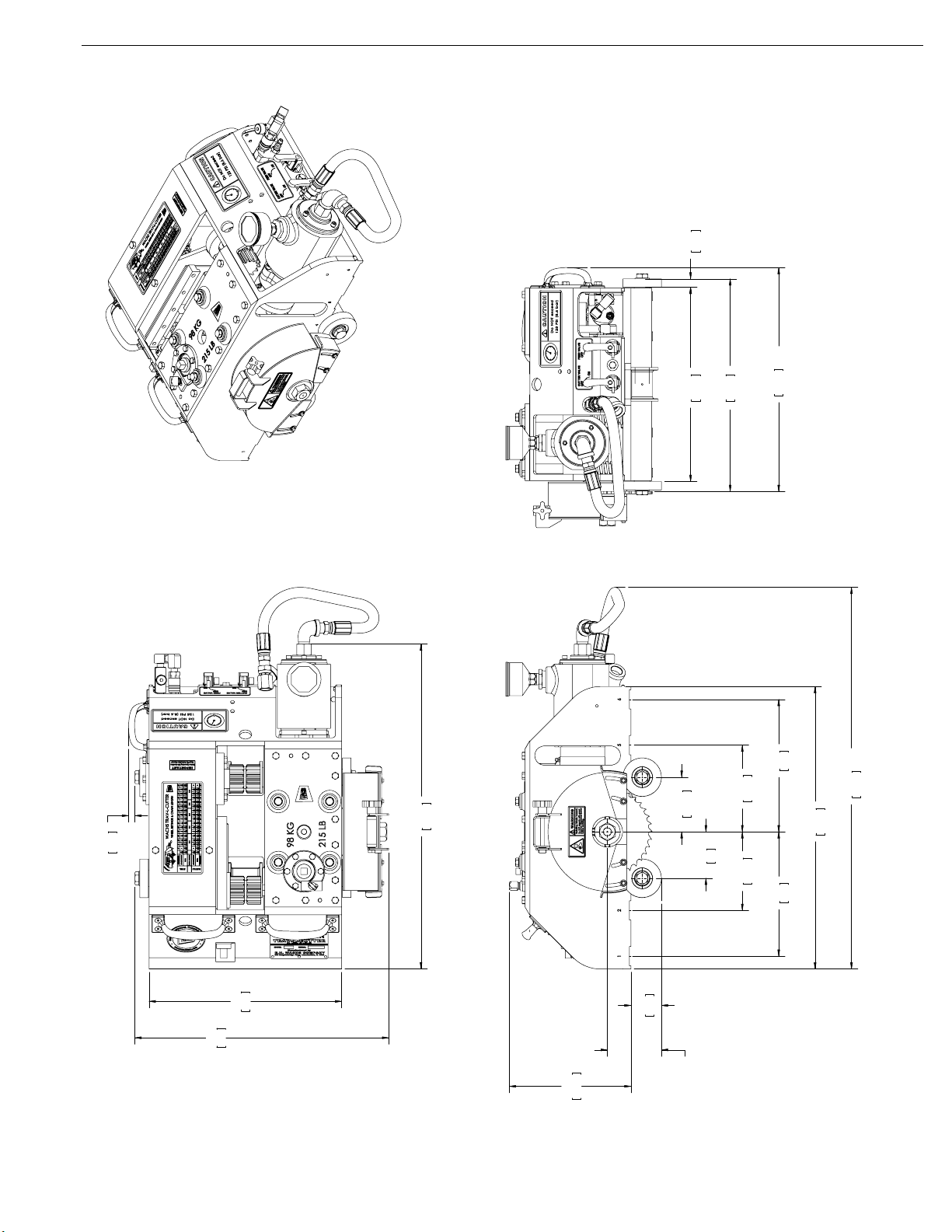
Operating Envelope
Trav-L-Cutter Assembly, Air Drive
02-000-01
15.12
384.2
16.56
420.5
CUT LINE
REF
17.43
CUT LINE
442.8
ARE MILLIMETERS
DIMENSIONS IN BRACKETS
.50
12.7
15.00
381
25.30
642.6
2.37
60.2
4.25
108.1
3.62
262
10.31
6.75
171.5
92
6.13
155.6
246
9.69
22.00
558.8
REF
29.72
754.9
19.76
502
9.48
240.7
BLADE TRAVEL
3.13 [79.4] MIN.
6.25 [158.8] MAX.
11
Chapter 3, About This Manual: Machine Specications
16
22
19
21
4
7
26
33
6
18
25
27
30
3
2023
20
20
8
5
34
36
28
26
2
12
38
15
39
11
9
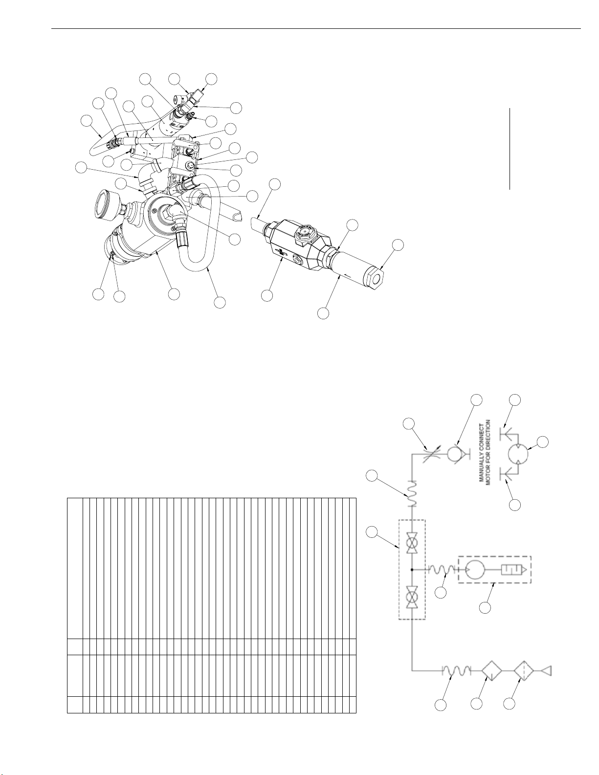
TRAV-L-CUTTER
AIR SYSTEM COMPONENTS
95 CFM [2690 l/min.]
125 PSI [8.6 bar] MAX.
INPUT REQUIREMENTS
DESCRIPTION
HOSE, 1/2" HP X 30" LONG
MOTOR, TRAVEL-AIR
CLAMP, AIR MOTOR
BODY, AIR FILTER
MANIFOLD, AIR
LABEL, PRESSURE-AIR (NOT SHOWN)
AIR MOTOR SUB-ASSEMBLY
1
1
1
QTY.
02-027-01
02-010-00
02-029-00
PART NUMBER
1
3
2
ITEM
HANDLE, AIR VALVE
HOSE, TRAVEL MOTOR
1
2
1
1
1
1
02-035-00
02-037-00
02-163-00
02-033-00
02-124-00
02-031-00
5
8
4
6
7
9
AIR LINE LUBRICATOR
FILTER ELEMENT (NOT SHOWN)
1
1
02-166-00
02-164-00
10
11
FLOW CONTROL VALVE 1/4"
SHIM, GEAR BOX (NOT SHOWN)
INLET AIR HOSE WHIP, 3/4" X 2"
LABEL, ON-OFF (NOT SHOWN)
1
1
1
02-191-00
02-171-00
02-185-00
12
13
14
COUPLING, 1/4 GALV LP
SSS, 10-32 X 5/16 CP (NOT SHOWN)
END PLUG
1
02-192-00
15
1/4 NPT F X 1/4 NPT M BRASS LP-90
NIPPLE, 1/4 X 5 GALV LP
1
4
3
1
1
02-212-00
90-058-04
90-044-53
90-058-05
90-058-02
17
20
16
18
19
ADAPTER, 1/4 NPT M X 1/4 NPT F SWIVEL-45
DISCONNECT, FEMALE 1/4 NPT M
DISCONNECT, MALE 1/4 NPT M
1
2
1
90-058-51
90-059-51
90-059-53
21
22
23
ADAPTER, 1/2 NPT F X 1/2 NPT F SWIVEL-STRAIGHT
NIPPLE, 1/2 CLOSE LP BLACK (NOT SHOWN)
1
90-098-01
24
1/2 HEX HP NIPPLE (NOT SHOWN)
ELBOW, 1/2-90 LP
1
1 ELBOW, 1/2-45 STREET
1
1
5 SHCS, 1/4-20 X 7/8 SS18-8
1 ELBOW, 1/2-90 STREET
90-150-08
90-098-05
90-098-58
90-098-04
90-098-06
90-098-57
29
25
28
30
26
27
HHCS, 5/16-18 X 1 SS18-8 (NOT SHOWN)
FHCS, 1/4-20 X 1 SS18-8 (NOT SHOWN)
WASHER, 1/4" HI COLLAR SS18-8
SSS, 1/4-20 X 3/4 SS18-8 (NOT SHOWN)
1 HHCS, 5/16-18 X 5/8 SS18-8
2
2
4
5
90-161-10
90-153-10
90-155-51
90-161-07
90-154-07
34
32
33
35
31
16
4
5
ELBOW, 3/4-45 LP STREET
WASHER, 5/16 FLAT SS18-8
BUSHING, 1-1/4 X 3/4 GLV REDUCING
NIPPLE, 3/4 CLOSE LP (NOT SHOWN)
1
1
1
1
90-218-03
90-165-52
90-218-10
90-218-01
36
39
37
38
22
2
3
12
11
MOTOR
SPINDLE
2323
6
FEED
MOTOR
INPUT
3/4" FEMALE NPT
9
12
Chapter 3, About This Manual: Machine Specications
ARE MILLIMETERS
DIMENSIONS IN BRACKETS
12.49
317.2
TYP
.66
16.8
15.12
384.2
16.56
420.5
CUT LINE
REF
18.28
CUT LINE
464.4
Operating Envelope
Trav-L-Cutter Assembly, Hydraulic Drive
02-000-02
REF
1.35
34.2
15.00
381
19.76
502
26.07
662.1
10.12
256.9
2.37
60.2
4.25
108.1
92
3.62
BLADE TRAVEL
3.13 [79.4] MIN.
6.25 [158.8] MAX.
6.75
6.13
171.5
155.6
10.31
9.69
262
246
22.00
558.8
REF
27.18
690.2
13
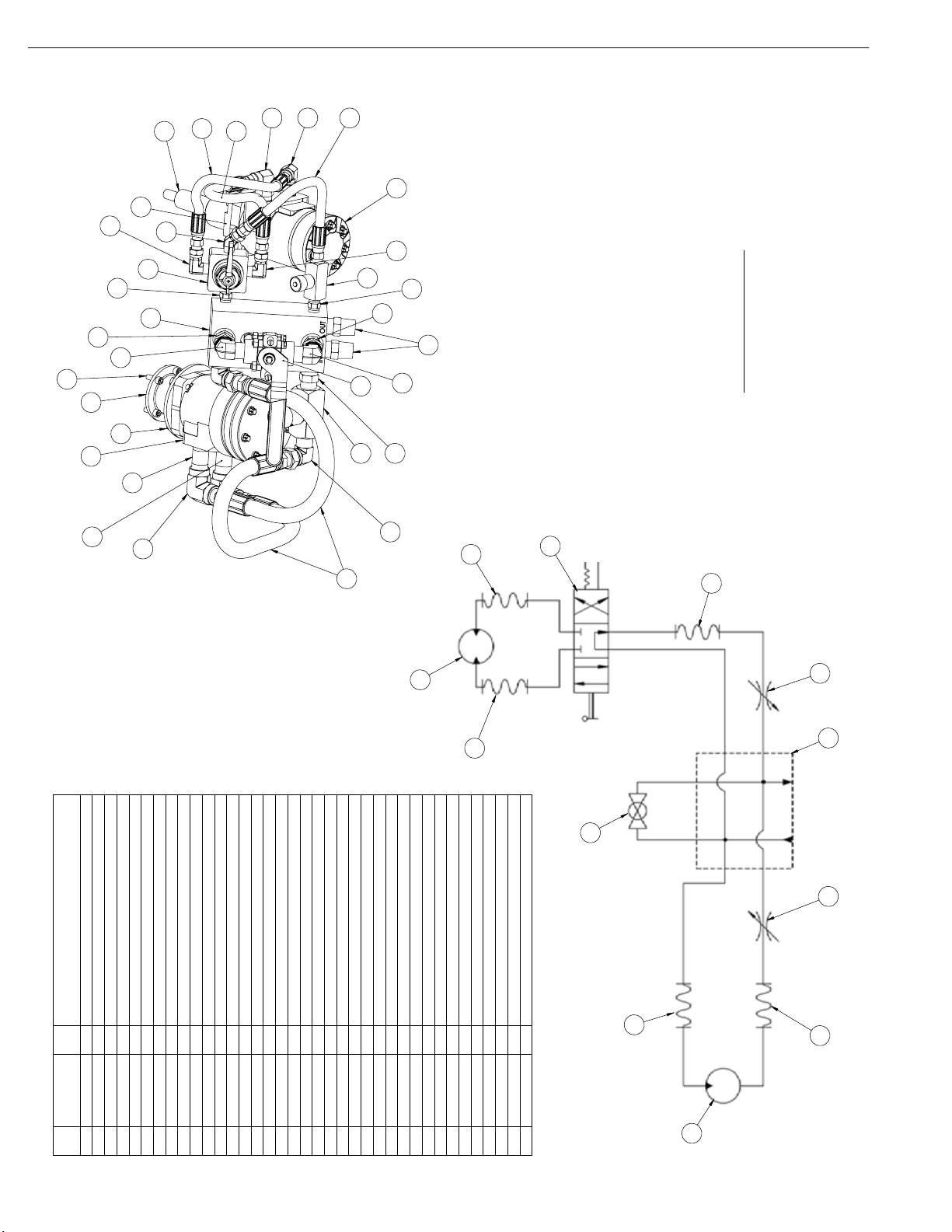
Trav-L-Cutter
8
9
20
23
29
30
6
5
25
19
13
16
26
36
24
28
211421
14
14
4
20
12
23
29
27
26
15
11
27
26
14
2
13
INPUT REQUIREMENTS
2000 PSI [138 bar] MAX.
TRAV-L-CUTTER
HYDRAULIC SYSTEM COMPONENTS
14
15 GPM [57 L/MINUTE]
DESCRIPTION
ADAPTER, CUTTER SPINDLE MOTOR
MOTOR COUPLING, DRIVE PIN
HYDRAULIC MOTOR, CUTTER SPINDLE
HOSE, 1/2" HP X 30" LONG
HYDRAULIC MOTOR, CARRIAGE DRIVE
LABEL, PRESSURE-HYD. (NOT SHOWN)
1
1
2
1
1
QTY.
BRACKET, MOUNTING-DRIVE MOTOR
DRIVE MOTOR ADAPTER
COUPLING, MOTOR (NOT SHOWN)
SHIM, HYDRAULIC GEAR BOX (NOT SHOWN)
1
1
1
1
1
FLOW CONTROL VALVE 1/4"
1/2" FLOW CONTROL VALVE
1/4" HP HOSE ASSEMBLY
1/4" 4-WAY VALVE REVERSING
1
3
1
1
KEY 1/8 X 1/2 #3 WOODRUFF (404) (NOT SHOWN)
1/2" ON/OFF VALVE
LABEL, TRAV-L-CUTTER HYD. (NOT SHOWN)
MANIFOLD
ADAPTER, 1/4 NPT M X 1/4 NPT F SWIVEL-45
ADAPTER, 1/4 NPT M X 1/4 NPT F SWIVEL-90
1
1
1
1
2
1
FEED
MOTOR
4
14
NIPPLE, 1/2" X 2" SCH 80 A106 B
NIPPLE, 1/4 HEX H.P.
BUSHING, 1/2 X 1/4 HP REDUCING (NOT SHOWN)
ELBOW, 1/4-90 HP STREET
2
2
ADAPTER, 1/2" NPT M X 1/2" NPT F SWIVEL-90
NIPPLE, 1/2" X 2-1/2" SCH 80 A106 B
1/2 HEX HP NIPPLE
2
4
1
3
1
FHCS, 1/4-20 X 1-1/4 SS18-8 (NOT SHOWN)
SHCS, 1/4-20 X 3/4, SS18-8
HHCS, 5/16-18 X 1 SS18-8 (NOT SHOWN)
ADAPTER, 1/2 NPT M X 1/2 ORB M - STRAIGHT
ADAPTER, 1/2" NPT F X 1/2" NPT F-90
2
2
HHCS, 5/16-18 X 2-3/4 SS18-8 (NOT SHOWN)
NUT, 5/16-18 HEX SS18-8 (NOT SHOWN)
WASHER, 5/16 FLAT SS18-8
HHCS, 3/8-16 X 7/8 SS18-8 (NOT SHOWN)
4
4
2
2
2
5
4
4 HHCS, 3/8-16 X 3/4 SS18-8
12
16
15
2
1/2" MALE NPT
INPUT/OUTPUT
11
2
14
02-027-01
02-009-00
02-199-00
PART NUMBER
3
2
1
ITEM
02-200-00
02-202-00
02-201-00
4
5
6
02-204-00
02-203-00
02-205-00
9
8
7
02-206-01
02-212-00
02-211-00
10
11
12
02-214-01
02-213-00
02-215-00
15
14
13
90-029-44
02-298-00
02-218-00
17
16
18
90-058-51
90-058-52
90-058-56
19
20
21
90-098-52
90-058-58
90-058-57
24
23
22
90-098-55
90-098-53
90-098-58
27
26
25
90-150-07
90-098-79
90-098-60
30
29
28
90-153-12
90-161-27
90-161-10
33
32
31
90-165-01
90-171-07
90-165-52
34
35
36
90-171-08
37
5
MOTOR
SPINDLE
Chapter 4, Setup and Operating Procedures
Chapter 4
Setup and Operating Procedures
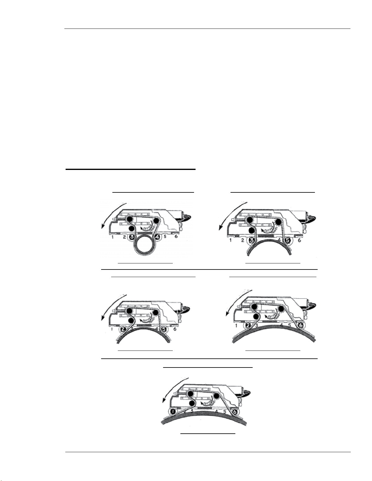
wheel seTTings
PIP E Ø 6.00” – 13.99” (152-355mm)
MACHINE TRAVEL
WHEEL POSITION 3 & 4
PIP E Ø 20.00” – 35.99” (508-914mm)
MACHINE TRAVEL
WHEEL POSITION 2 & 5
PIP E Ø 48.00” – 72.00” (1219-1829mm)
PIP E Ø 14.00” – 19.99” (356-508mm)
MACHINE TRAVEL
WHEEL POSITION 3 & 5
PIP E Ø 36.00” – 47.99” (914-1219mm)
MACHINE TRAVEL
WHEEL POSITION 2 & 6
MACHINE TRAVEL
WHEEL POSITION 1 & 6
E.H. Wachs Part No. 02-MAN-01, Rev. A 15

Trav-L-Cutter
chain lengThs
PIPE
SIZE
TYPE
DI/S¹
6”
8”
10”
12”
14”
16”
18”
20”
24”
30”
36”
42”
48”
54”
60”
72” S 72.00" (1829mm) 38" (965mm) 02-457-72 240" (6096mm) 02-450-72
S 6.625” (168mm)
Di 6.90” (175mm)
S 8.625" (219mm)
Di 9.05" (230mm)
S 10.75" (273mm)
Di 11.10" (282mm)
S 12.75" (324mm)
Di 13.20" (335mm)
S 14.00" (356mm)
Di 15.30" (389mm)
S 16.00" (406mm)
Di 17.40" (442mm)
S 18.00" (457mm)
Di 19.50" (495mm)
S 20.00" (508mm) 2" (51mm) 02-457-20 78" (1981mm) 02-450-20
Di 21.60" (549mm) 7" (179mm) 02-457-20-D 83" (2108mm) 02-450-20-D
S 24.00" (610mm)
Di 25.80" (655mm) 96" (2438mm)
S 30.00" (762mm)
Di 32.00" (813mm) 116" (2946mm)
S 36.00" (915mm)
Di 38.30" (973mm) 133" (3378mm)
S 42.00" (1067mm)
Di 44.50" (1130mm) 152" (3861mm)
S 48.00" (1219mm) 17" (432mm) 02-457-48 164" (4166mm) 02-450-48
Di 50.80" (1290mm) 21" (533mm) 02-457-48-D 173" (4394mm) 02-450-48-D
S 54.00" (1372mm)
Di 57.26" (1454mm) 194" (4928mm)
S 60.00" (1524mm) 18" (458mm) 02-457-60 202" (5131mm) 02-450-60
Di 61.61" (1565mm) 13" (330mm) 02-457-60-D 207" (5258mm) 02-450-60-D
PIPE DIA.
ADD ON
LENGTH²
0 02-457-06 42” (1067mm)
5” (127mm) 02-457-08 47” (1194mm)
8” (203mm) 02-457-10 55” (1397mm) 02-450-10
6” (152mm) 02-457-12 61” (1549mm) 02-450-12
2” (51mm) 02-457-14 63” (1600mm) 02-450-14
6” (152mm) 02-457-16 69” (1752mm) 02-450-16
7” (179mm) 02-457-18 76” (1930mm) 02-450-18
13” (330mm) 02-457-24
20” (508mm) 02-457-30
17” (432mm) 02-457-36
19” (482mm) 02-457-42
20” (508mm) 02-457-54
PART NUMBER TOTAL LENGTH
91" (2312mm) 02-450-24
111" (2819mm) 02-450-30
128"(3251mm) 02-450-36
147" (3734mm) 02-450-42
184" (4674mm)
ACCUMULATED
CHAIN ASSEMBLIES
N/A
02-450-54
¹ S - STEEL PIPE MEASUREMENTS - PER ASME B36.19M-2004
DI- DUCTILE-IRON PIPE MEASUREMENTS - PER ANSI/AWWA C151/A21.51-91
² REQUIRES 42” (1067mm) BASE CHAIN AND ALL PREVIOUS ADD ON LENGTHS
16 Part No. 02-MAN-01, Rev. A E.H. Wachs

Chapter 4, Setup and Operating Procedures: Wheel Settings and Chain Length
wheel seTTings and chain lengTh
MACHINE TRAVEL
WACHS TRAV-L-CUTTER
WHEEL SETTINGS & CHAIN LENGTH
PIPE DIAMETER
ADD ON LENGTH
STEEL
DUCTILE
TOTAL
WHEEL POSITION
ADD ON LENGTH
TOTAL
PIPE DIAMETER
6” 8” 10” 12” 14” 16” 18” 20” 24” 30” 36” 42” 48” 54” 60” 72”
IN
MM
IN
MM
IN
MM
IN
MM
5
0
12782036152251615271792511333020508174321948217432205081845838965
42
1067471194551397611549631600691752761930781981912312
3 & 4 3 & 5 2 & 5 2 & 6 1 & 6
5
0
1278203615225161527179717913330205081743219482215332050813330
42
1067471194551397611549631600691752761930832108962438
6” 8” 10” 12” 14” 16” 18” 20” 24” 30” 36” 42” 48” 54” 60” 72”
111
2819
116
2946
128
3251
133
3378
147
3734
152
3861
164
4166
173
4394
184
4674
194
4928
Chain Length Calculations
You can calculate the required chain length for any size pipe using the following formulas.
202
5131
207
5258
240
6096
X
X
Pipe O.D. Wheel Positions Chain length Formula
6.0”-13.99”
(168-355 mm)
14”- 19.99”
(356-507 mm)
20”-35.99”
508-914 mm
36”-47.99”
(915-1218 mm)
48”-72”
(1219-1829 mm)
3 and 4 3.235 x (Pipe Diameter in Inches) + 19.06”
3.235 x (Pipe Diameter in mm) + 484 mm
3 and 5 3.204 x (Pipe Diameter in Inches) + 16.33”
3.204 x (Pipe Diameter in mm) + 415 mm
2 and 5 3.175 x (Pipe Diameter in Inches) + 14.98”
3.175 x (Pipe Diameter in mm) + 380 mm
2 and 6 3.162 x (Pipe Diameter in Inches) + 12.82”
3.162 x (Pipe Diameter in mm) + 326 mm
1 and 6 3.149 x (Pipe Diameter in Inches) + 12.61”
3.149 x (Pipe Diameter in mm) + 320 mm
Note that there is some overlap in acceptable wheel positions between size ranges.
E.H. Wachs Part No. 02-MAN-01, Rev. A 17
 Loading...