

Page 1

RS-2
E.H. Wachs Water Utility Products
600 Knightsbridge Parkway, Lincolnshire, IL 60069
RS-2
i
PIPE & VALVE
MAINTENANCE MACHINERY
Mod. RS-2 S/N:
E.H. WACHS COMPANY
100 Shepard St. Wheeling, IL 60090
PART NUMBER: 78-MAN-01
REVISION NO: R1_1
Patent Pending
Revised:
Jan. 2004
1
Page 2

RS-2
TABLE OF CONTENTS
SECTION I INTRODUCTION & SPECIFICA TIONS...................................................................3-4
SECTION II SAFETY INSTRUCTIONS............................................................................................5
SECTION III SET UP & OPERA TING PROCEDURES............................................................6-16
SECTION IV CHARTS & SCHEMA TICS..................................................................................17-19
Electric RS-2...............................................................................................................19
Hydraulic RS-2............................................................................................................19
Pneumatic RS-2..........................................................................................................19
SECTION V BILL OF MA TERIALS...........................................................................................20-33
Main Head Assembly............................................................................................21-22
Revolution Counter Assembly ..............................................................................21-22
Hydraulic Drive Assembly.....................................................................................21-22
Pneumatic Drive Assembly..................................................................................23-24
Electric Drive Assembly........................................................................................25-26
ACCESSORIES...................................................................................................27-30
Universal Handwheel............................................................................................27-28
1” Inch Drive Adapter............................................................................................27-28
Handwheel Adaptor Plate....................................................................................27-28
General Accessories............................................................................................29-30
Cleco Air Motor......................................................................................................31-33
SECTION VI ORDERING INFORMA TION......................................................................................34
2
Page 3

RS-2
SECTION I INTRODUCTION-SPECIFICA TIONS
INTRODUCTION:
The RS-2 Portable V alve Operator for rising
and non-rising stem valves offers reliable
opening and closing of water , wastewater,
pipeline and petroleum valves.
The RS-2 offers these advantages:
! Available in Hydraulic, Pneumatic or
Electric Drive.
! Operate all Rising & Non-Rising Stem
valves. From 6” to 60”.
! 4” Opening for operating Rising Stem
Valves.
! Mount to any Hand Wheel with
“Universal Hand Wheel Adapter”.
! Forward and Reverse operation.
! Variable Speed Control.
! Built in easy view LCD counter.
OPERATE YOUR RS-2 AND OTHER
Universal Handwheel Adaptor
VALVE TURNING AND PIPE
CUTTING EQUIPMENT WITH....
WACHS WACHS
WACHS
WACHS WACHS
HYDRA HYDRA
HYDRA
HYDRA HYDRA
! Cart Mounted / Electric Start
! 9 to 15 H.P. Gas or Diesel Engines
! 8 to15 G.P.M. units Available
ULIC POULIC PO
ULIC PO
ULIC POULIC PO
WER UNITWER UNIT
WER UNITS
WER UNITWER UNIT
Electric Hydraulic Pneumatic
3
Page 4

RS-2
SECTION I INTRODUCTION-SPECIFICA TIONS
SPECIFICATIONS
CAPACITY: Operate all rising and non-rising stem valves from 6” to 60”, which require mechanized turning.
DRIVE: Lightweight Aluminum gear box. Two stage reduction.
DRIVE HUB: 4” opening for rising stem valve operation.
REVOLUTION
COUNTER: Built in “easy view” LCD Counter. Push button reset counts 1/10 revolution increments, forward and
FINISH: Aluminum gear housing, Zinc plated handle.
DIMENSIONS: 42” length, 4.75” width, 10.3” height
WEIGHT : 40-45 lbs.
POWER
REQUIREMENTS: Air drive, 60 cfm @ 90 psi.
MOTOR Adjustable speed.
CONTROLS: Forward and reverse dial.
OPTIONAL Universal Handwheel Adaptor (pn: 09-405-00) Dedicated Handwheel Adapter Plate (pn: 09-404-00)
ACCESSORIES: 1” Square drive adopter (pn: 09-402-00) 8 ft. Valve Key (pn: 05-402-00)
Planetary motor drive. Steel Ring and Pinion secondary drive.
reverse automatically.
AIR ELECTRIC HYDRAULIC
Electric, 110 volt AC
(15 amps or 3500 watt generator)
2 Speed gear box
Forward and reverse control knob.
Hydraulic, 8 gpm @ 1800 psi
Variable speed.
Adjustable torque control.
Forward and reverse control valve
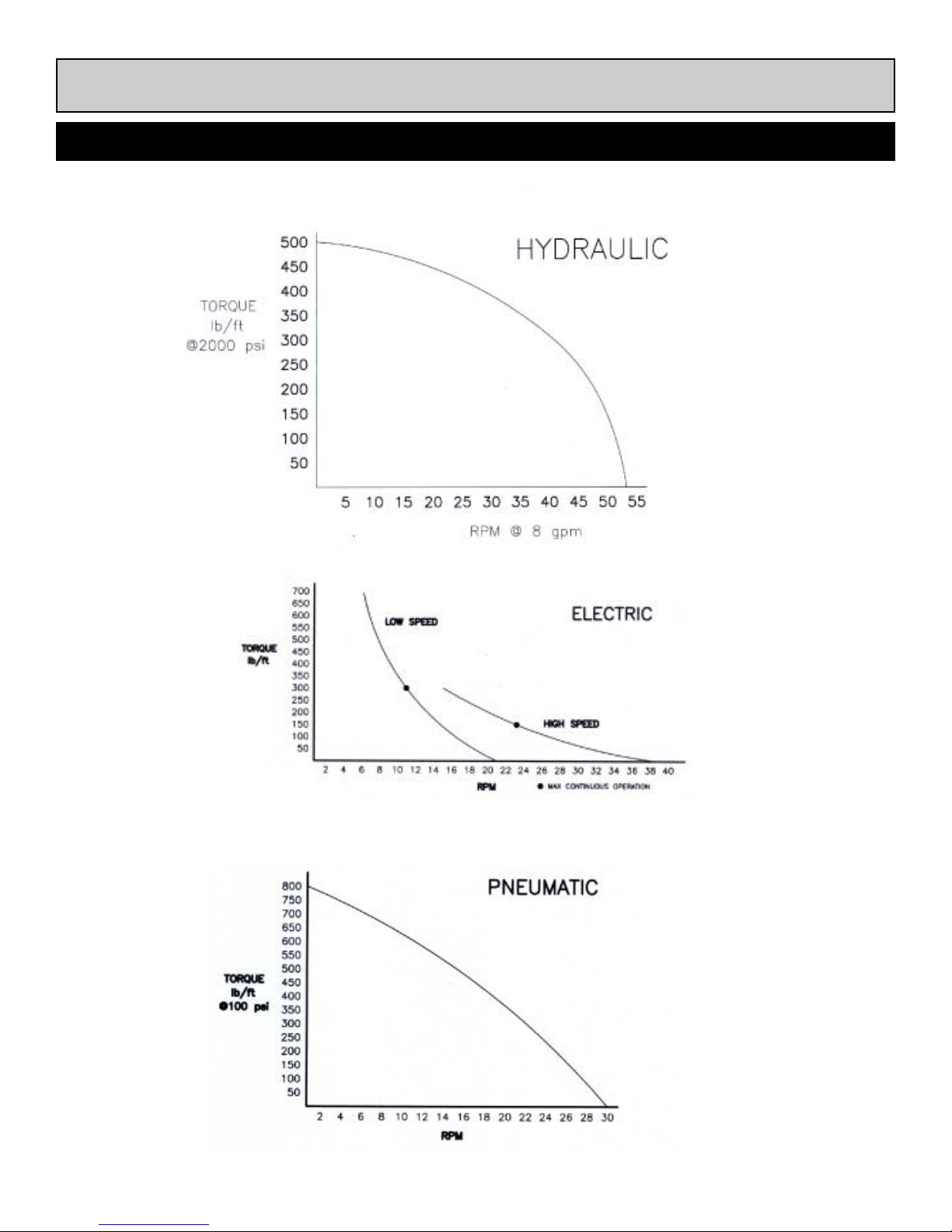
*NOTE: SEE PAGE 19 FOR PEAK TORQUE AND MAXIMUM RPM OUTPUT
4
Page 5

RS-2
SECTION II SAFETY INSTRUCTIONS
Read the Following thoroughly before proceeding
Since 1883, EH Wachs has built a reputation for
quality and a commitment to consumer satisfaction.
In accordance with this, Wachs must take on the
added responsibility of doing our best to assure the
safest use of our equipment.
We have assembled a list of safety reminders to
aid in creating the safest possible working environment. We recommend that the precautionary steps
listed there be closely observed.
1. READ THE OPERATING MANUAL!!
Reading the setup and operating instructions prior to
beginning the setup procedures can save valuable time
and help prevent injury to operators or damage to ma-
chines.
2. INSPECT MACHINE & ACCESSORIES!
Prior to machine setup physically inspect the machine
and it's accessories. Look for worn tool slides, loose bolts
or nuts, lubricant leakage, excessive rust, etc. A properly
maintained machine can greatly decrease the chances
for injury.
3. ALWAYS READ PLACARDS & LABELS!
All placards, labels and stickers must be clearly legible
and in good condition. Replacement labels can be pur-
chased from the manufacturer.
ALWAYS WEAR PROTECTIVE EQUIPMENT:
WARNING
Impact resistant eye protection
must be worn while operating or
working near this tool.
For additonal information on eye and face protection, refer to
federal OSHA regulations, 29 Code of Federal Regulations,
Section 1019.133., Eye and Face Protection and American
National Standards Institute, ANSI Z87.1, Occupational and
Educational Eye and Face Protection. Z87.1 is available
from the American National Standards Institute, Inc., 1430
Broadway, New York, NY 10018
CAUTION
Personal hearing protection is required at all times when operating or working near this tool.
Hearing protectors are required in high noise areas, 85dBA
or greater. The operation of other tools and equipment in the
area, reflective surfaces, process noises and resonant
structures can substantionally contribute to and increase
the noise level in the area. For additional information on
hearing protection, refer to federal OSHA regulations , 29
Code of Federal Regulations, section 1910.95, Occupational Noise Exposure and ANSI S12.6 Hearing Protectors.
4. KEEP CLEAR OF ROTATING PARTS!
Keep hands, arms and fingers clear of all rotating or
moving parts. Always turn machine off before attempting
any adjustments requiring contact with the machine or it's
accessories.
5. SECURE LOOSE CLOTHING & JEWELRY!
Loose fitting clothing, jewelry; long, unbound hair can get
caught in the rotating parts on machines. By keeping
these things secure or removing them you can greatly
reduce the chance for injury.
6. KEEP WORK AREA CLEAR!
Be sure to keep the work area free of clutter and nonessential materials. Only allow those personnel directly
associated with the work being performed to have access
to the area if possible.
CAUTION
Some individuals are suseptible to
disorders of the hands and arms
when exposed to tasks which involve repetitive motions and/or vibration. Disorders such as Carpal
Tunnel Syndrome and Tendonitis
can be caused or aggravated by
repetitious, forceful exertions of the
hands and arms.
! Use minimum hand grip force.
! Keep wrists straight
! Avoid prolonged, continuous vibration exposure
! Avoid repeated bending of wrists and hands.
! Keep arms and hands warm and dry.
5
Page 6

RS-2
Section III
Set Up
&
Operating Procedures
6
Page 7
RS-2
SECTION III SET-UP AND OPERATION
necessary to start with a nut and stem
jammed against the bonnet, and there will be
no guesswork about which way to turn
the nut because the valve will be free. Also, if
it is inadvertently turned the wrong way , one
or two turns can be made before a positive
stops occurs, and by reversing direction, full
operation of the valve can be effected.
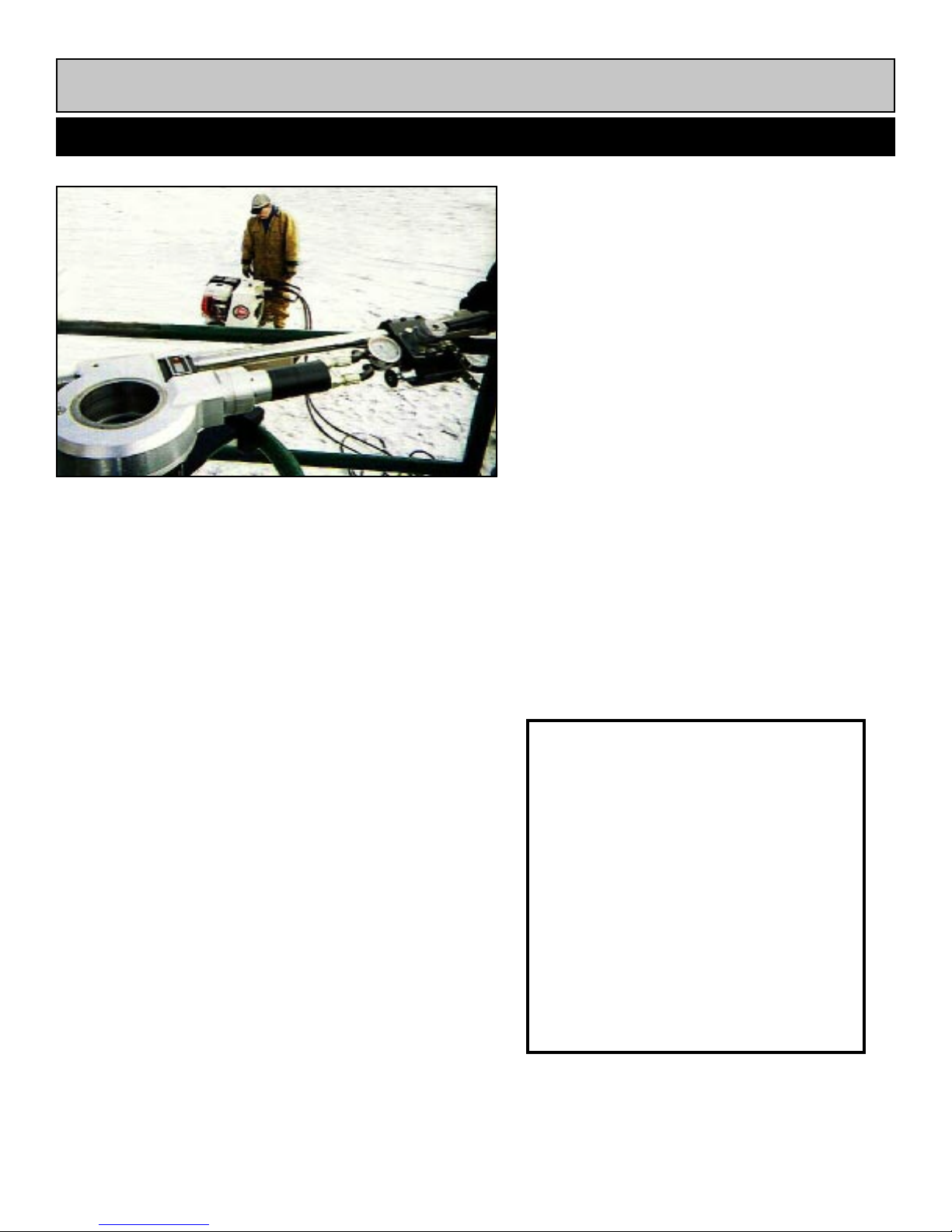
Using the RS-2 machines to operate valves
is easier on the valve because a steady
turning torque is applied rather than jerky
motions. This prevents the stem breakage
that is sometimes caused by turning the
valve by hand. Also, more valves can be
Valve Maintenance Procedure
A valve that has not been operated for a number of
years needs to be closed by using a series of up
and down motions. Occasionally , crews attempting
to close a difficult valve use a T -handle or a cheater
bar, applying a great deal of pressure in one direction simply to force the valve closed. The correct
way to exercise a valve is to begin with a steady
amount of torque in the direction necessary to close
the valve, moving through five to ten rotations, then
the direction should be reversed for two or three
revolutions, followed by five or ten more turns in the
closing direction. This procedure should be repeated until full closure is attained.
The reason for the cautious approach is that
tuberculation and sediment have probably built up
on the gates, stem, and slides. By using the procedure described, water in the system can flush the
debris that has broken away from the gate slide.
The stem is exercised through the series of
up and down motions. Once the valve has been fully
closed, it should be opened a few turns so that the
higher velocity water flowing under the gates can
move the remainder of the sediment downstream.
After the valve is reopened, it should be turned in
the closing direction one or two revolutions. Thus,
the next time the valve is operated, it will not be
turned in less time. A further advantage is that
information about each valve can be generated automatically by the revolution counter
and torque gauges for inclusion on permanent records.
HOW TO DETERMINE AN
UNKNOWN VALVE ROTATION:
When the direction to turn the valve
stem is not known, select a rotation
direction and proceed with caution. If
resistance is felt, immediately reverse
the rotation. Continue this procedure,
reversing direction when resistance is
felt, until a free turning direction is
achieved. Document the direction,
open or closed position, and number
of turns required.
7
Page 8
RS-2
SECTION III SET-UP AND OPERATION
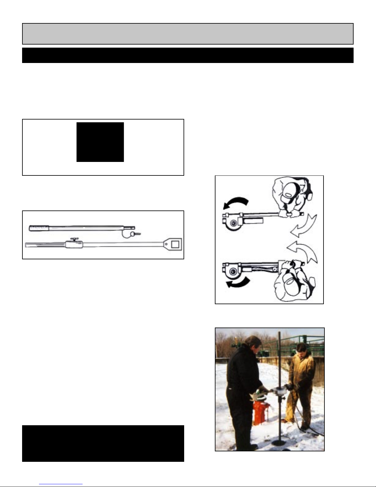
I. SET UP PROCEDURE (V alve Key & Socket):
1. Insert 1” drive adaptor into RS-2 drive hub, secure
with 1/4 20x5/8” SHCS. (Ref. 1)
1” Square Drive Adaptor
Ref. 1
2. Insert valve key and socket into valve. (Ref. 2)
Valve Operator
Extension Handle
Stop Collar
Valve Key & Socket
II. OPERA TOR POSITIONING
Standing on the wrong side of the machine will allow
the handle to PUSH against the operator and can
knock him off balance or pin him against an obstacle if
torque suddenly increases. When positioned properly,
an increase in torque will PULL the handle and control
out of the operator’s hand and stop the machine (See
illustrations below).
IMPORTANT: Always refer to the manual or the valve
direction decal located on valve handle for correct
operation positions.
Ref. 2
3. Install stop collar at a comfortable operating height
to support the weight of the RS-2.
4. Mount the RS-2 on the valve key and rest on stop
collar. Connect the power source.
5. Zero the counter when valve is ready to be turned
by pressing the red reset button on the counter face.
Always use the counter to determine the number of
rotations the valve has turned.
6. Determine direction of valve rotation and which
side of RS-2 to operate from. The operator should
stand on the side of the machine which allows the
torque to PULL the machine handle away from his
body .
CAUTION: The RS-2 is capable of producing up
to 800 ft./lbs. of torque to turn valves. It is very
!
!
important that proper procedure be exercised
when using the valve operating machine.
Operator should always change sides for opposite rotation
V alve Key Operation
8
Page 9
RS-2
SECTION III SET-UP AND OPERATION
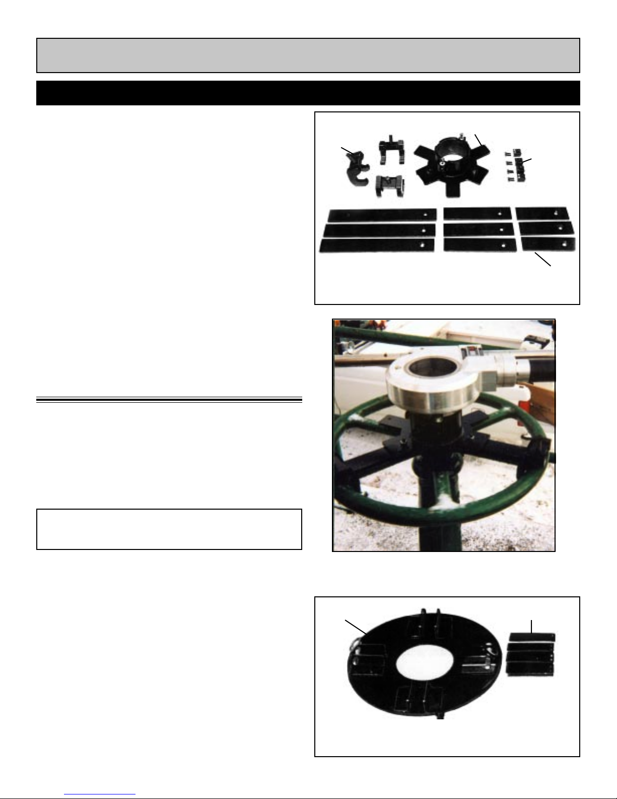
I. SET UP PROCEDURE
(
Universal Handwheel Adapter)
1. Install the 4 handwheel fingers onto the RS-2
rotating drive hub slots with the provided 1/4 20x1”
socket head cap screws.
2. Measure the valve handwheel to determine the
correct length torque arm required to mount to the
universal hand wheel. Install the torque arms using
the provided flat head screws and nuts.
3.Set the assembly over the rising stem valve. Center
the opening of the universal handwheel adapter
over the rising stem screw.
4.Mount the 3 straddle clamps over the torque arms
and under the valve handwheel and secure the
assembly with the 1/2 13x2” square head screws in
the straddle clamps.
I. SET UP PROCEDURE
(
Mounting Dedicated Handwheel
Adaptor Plate)
1. The dedicated adaptor plate must be mounted to
rising stem valve with U-bolts supplied with your
dedicated adaptor plate. Holes must be drilled into
adapter plate to bolt plate to handwheel spokes.
Universal Handwheel
Straddle Clamps
Drive Fingers
Torque Arms
Universal Handwheel Adapter Assembly
NOTE: Center dedicated handwheel plate
""
"
""
2. After mounting adapter plate, bolt fingers to RS-2
drive hub using the slots provided for this purpose,
located on bottom of actuator , using 1/4 20x5/8”
socket head cap screws.
3. Place RS-2 on adapter dedicated plate so that
fingers rest in adapter plate slots.
4. Insert “fast-pins” in holes provided to lock actuator
on adapter plate.
5. Place the RS-2 onto the Universal hand wheel
adopter by inserting the 4 drive fingers into the 4
mounting slots on the Universal handwheel adopter.
Insert the swing bolt assemblies into the slots and
tighten the nuts to secure the assembly .
hole over center of rising stem screw.
Adapter Plate
9
Universal Handwheel Assembly
Drive Fingers
Dedicated Handwheel Adapter Assembly
Page 10
RS-2
SECTION III SET-UP AND OPERATION
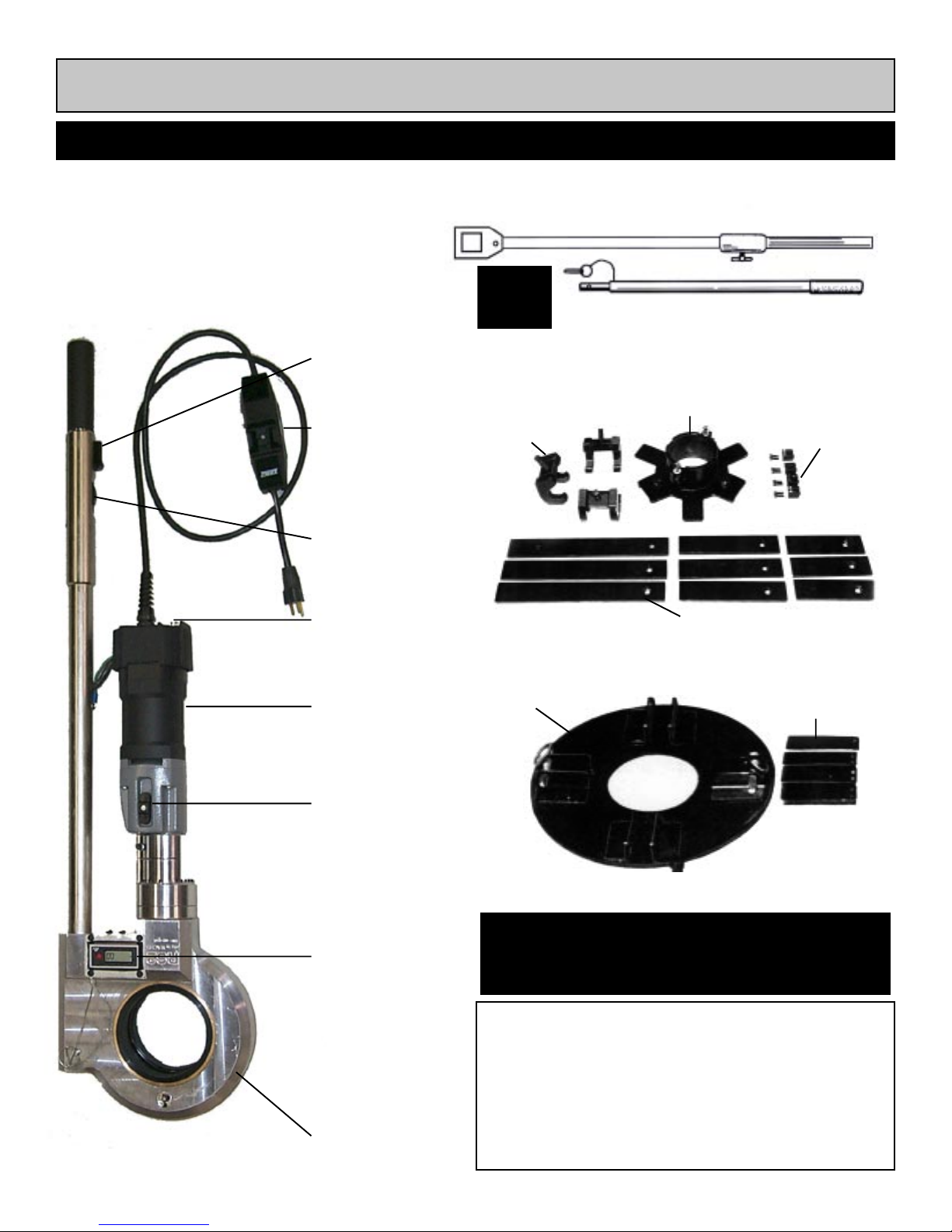
CONTROLS AND COMPONENTS
ELECTRIC RS-2
On/Off
Trigger
GFI
Ground Fault
Interrupter
Forward/Reverse
Switch
Reset Button
Valve Socket
1” Drive Adapter
Straddle Clamps
Valve Key Operation
Stop Collar
Valve Operator
Extension Handle
Universal Handwheel Operation
Universal Handwheel
Drive Fingers
Long, Medium, Short Torque Arms
Electric Motor
High/Low
Torque
Setting
Switch
1/10th Counter
w/Reset Button
Power Head
Dedicated Handwheel Operation
Drive Plate
Lifting Handles
CAUTION: DO NOT connect or disconnect hoses
!
!
INTRODUCTION
It is impossible to determine how much torque a
valve stem can take before breaking. Size, age,
condition, tuberculation, and period of time since
last operation will have an effect to this. The
recommended start-up procedure for operating a
valve is to set the RS-2 to its lowest torque setting.
10
to valve operator or power source while power
source is operating.
Drive Fingers
Page 11

RS-2
SECTION III SET-UP AND OPERATION
OPERATING PROCEDURE:
ELECTRIC RS-2
CAUTION: Before beginning turning sequence,
know which direction to turn the valve to avoid
breaking the valve stem.
1. Af ter plugging in power cord, push reset button
on GFI to power up unit.
2. Set speed control knob to high speed/low
torque setting (see illustration below).
NOTE: If the motor overload circuit breaker
pops while attempting to free a frozen valve,
reset the circuit breaker by pressing the
""
"
""
3. If the valve does not move in either direction,
switch speed control to low speed/high torque
setting.
Once the valve has started turning, return the
speed control switch to the high speed/low torque
setting. This procedure will assure you that the
machine stops operating as soon as any type of
obstruction is encountered or when the valve is
seated.
reset button and attempt to free the valve
again before switching to the low speed/
high torque setting.
CAUTION: Only use extension cords rated
for 10 AMPS or higher.
NOTE: More torque will be required to seat,
""
"
""
DURING OPERATION:
When operating a valve, a build up of torque can
be felt by the operator. When this occurs, it is a
sign of either build up of material in the valve gate
slides or that the end of travel is approaching. The
operator should change sides and reverse the
valve direction for a few turns, doing this each
time resistance is felt. This method of exercising
cleans out tuberculin and other contaminant build
up. The counter will keep track of how many turns
you have put on the valve.
unseat or clear tuberculin from the valve.
11
Page 12
RS-2
SECTION III SET-UP AND OPERATION
CONTROLS AND COMPONENTS
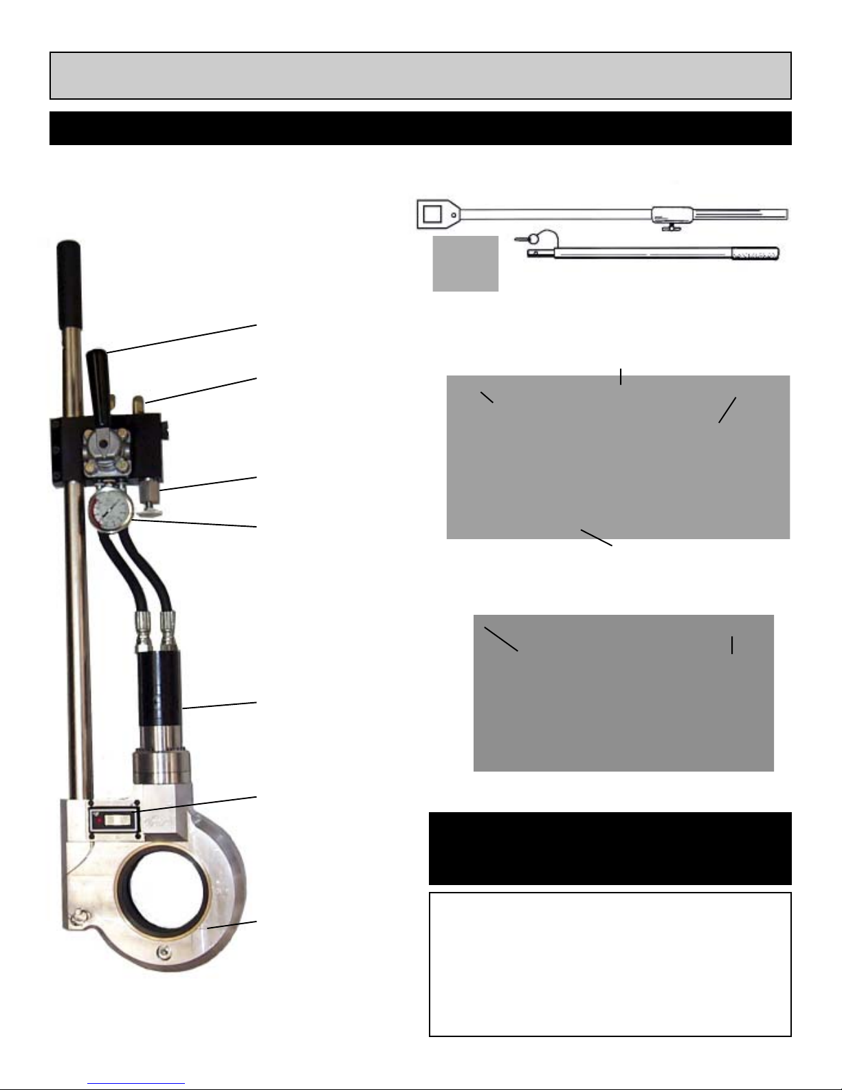
HYDRAULIC RS-2
Forward/Reverse
Lever
Supply Inlet
Torque Control Knob
Torque Gauge
Valve Socket
1” Drive Adapter
Straddle Clamps
Valve Key Operation
Stop Collar
Valve Operator
Extension Handle
Universal Handwheel Operation
Universal Handwheel
Drive Fingers
Long, Medium, Short Torque Arms
Hydraulic Motor
1/10th Counter
w/Reset Button
Power Head
Dedicated Handwheel Operation
Drive Plate
Lifting Handles
CAUTION: DO NOT connect or disconnect hoses
!
Ì
INTRODUCTION
It is impossible to determine how much torque a
valve stem can take before breaking. Size, age,
condition, tuberculation, and period of time since
last operation will have an effect to this. The
recommended start-up procedure for operating a
valve is to set the RS-2 to its lowest torque setting.
12
to valve operator or power source while power
source is operating.
Drive Fingers
Page 13

RS-2
SECTION III SET-UP AND OPERATION
OPERATING PROCEDURE:
HYDRULIC RS-2
CAUTION: Before beginning turning sequence,
!
Ì
1. Rotate torque control knob counterclockwise
to the lowest torque setting.
2. Engage the “power on” handle in either forward
or reverse direction. If valve does not turn, release
handle and engage in the opposite direction.
""
"
""
know which direction to turn the valve to avoid
breaking the valve stem.
NOTE: When lever is depressed, torque
indicator will read the torque value being
applied to valve stem.
3. Continue this process, increasing the torque value
1/2 turn on the torque control until valve stem
breaks free. This method ensures that only enough
torque is supplied to turn the valve. Once the valve
has started turning, reduce the torque setting to the
lowest setting which will keep the machine operating. This procedure assures you that the machine
will stop operating as soon as any type of obstruc
tion is encountered or valve begins to seat.
NOTE: More torque will be required to seat,
""
"
""
DURING OPERATION:
When operating a valve, a build up of torque can be
felt by the operator. When this occurs, it is a sign of
either build up of material in the valve gate slides or
that the end of travel is approaching. The operator
should change sides and reverse the valve direction
for a few turns, doing this each time resistance is felt.
This method of exercising cleans out tuberculin and
other contaminant build up. The counter will keep track
of how many turns you have put on the valve.
unseat or clear tuberculin from the valve.
13
Page 14
RS-2
SECTION III SET-UP AND OPERATION
CONTROLS AND COMPONENTS
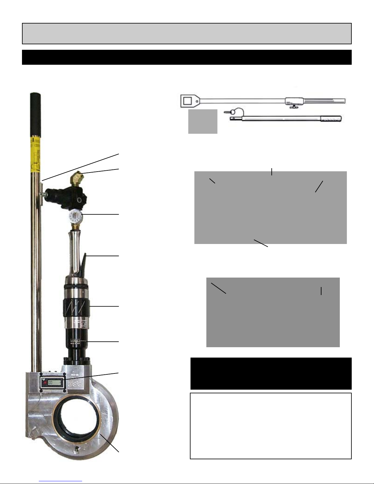
PNEUMATIC RS-2
Torque Adjustment
Air Inlet
Torque Gauge
On/Off
Trigger
Valve Socket
1” Drive Adapter
Straddle Clamps
Valve Key Operation
Stop Collar
Valve Operator
Extension Handle
Universal Handwheel Operation
Universal Handwheel
Drive Fingers
Long, Medium, Short Torque Arms
Dedicated Handwheel Operation
Forward/Reverse
Ring
Pneumatic Motor
1/10th Counter
w/Reset Button
Power Head
Drive Plate
Lifting Handles
CAUTION: DO NOT connect or disconnect hoses
!
Ì
INTRODUCTION
It is impossible to determine how much torque a
valve stem can take before breaking. Size, age,
condition, tuberculation, and period of time since
last operation will have an effect to this. The
recommended start-up procedure for operating a
valve is to set the RS-2 to its lowest torque setting.
to valve operator or power source while power
source is operating.
Drive Fingers
14
Page 15

RS-2
SECTION III SET-UP AND OPERATION
OPERATING PROCEDURE:
PNEUMATIC RS-2
1. Rotate torque control knob counterclock wise to the
lowest torque setting
2. Press the power on lever in either forward or re-
verse direction. If valve does not turn, release lever
and rotate motor direction ring on motor body and
repeat procedure.
NOTE: When lever is depressed, torque
""
"
""
indicator will read the torque value being
applied to valve stem.
DURING OPERATION
When operating a valve, a build up of torque can
be felt by the operator. When this occurs, it is a
sign of either build up of material in the valve gate
slides or that the end of travel is approaching. The
operator should change sides and reverse the
valve direction for a few turns, doing this each time
resistance is felt. This method of exercising cleans
out tuberculin and other contaminant build up. The
counter will keep track of how many turns you have
put on the valve.
3.Continue this process, increasing the torque value
1/4 turn on the torque control until valve stem breaks
free. This method ensures that only enough torque
is supplied to turn the valve. Once the valve has
started turning, reduce the torque setting to the
lowest setting which will keep the machine operating. This procedure assures you that the machine
will stop operation as soon as any type of obstruction is encountered or valve begins to seat.
NOTE:
1. More torque will be required to seat, unseat
or clear tuberculin from the valve.
""
"
""
!
Ì
2. Maximum torque cut-off can be reset by
free running RS-2 with no load and
adjusting torque control until torque indicator
gauge reads desired torque cut-off.
CAUTION: RS-2 Must be used with an inline
filtration system to stop water and air borne
contaminents. FAILURE TO COMPLY WILL
DAMAGE MOTOR AND VOID WARRANTY.
USE OF AIR LINE OIL:
An in-line oiling system should be utilized when
operating the pneumatic Pow-R-Drive II to lubricate
motor on a continuous basis.
When continuous load and high torque settings
are required, the use of an antifreeze oil to
lubricate the motor will reduce ice buildup and
maintain motor performance. (Kilfrost AntiFreeze Solution, Wachs Part No. 02-403-00)
15
Page 16
RS-2
SECTION III SET-UP AND OPERATION
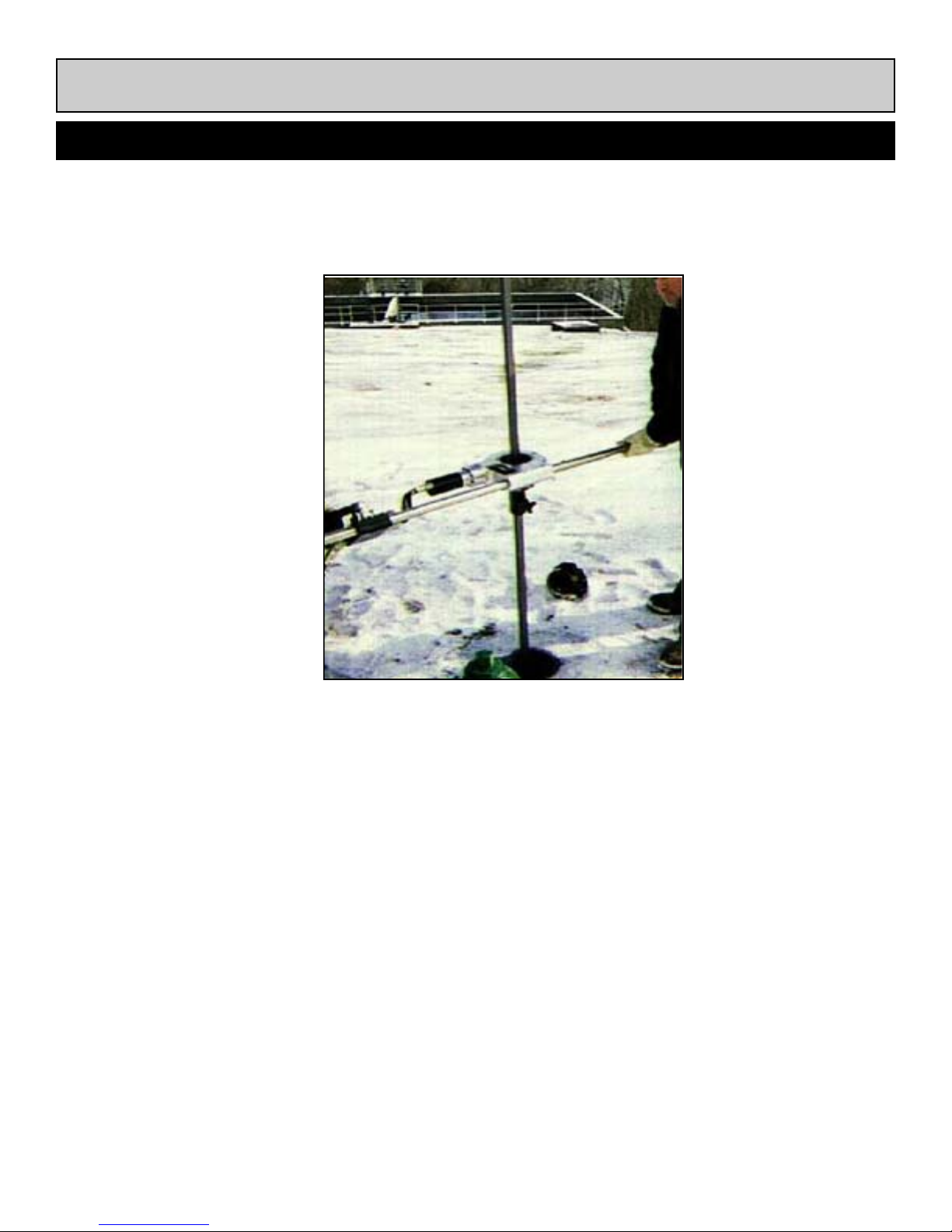
TWO OPERATOR OPERATION:
An extension handle is provided with each
RS-2. It is designed to be inserted into the end
of the handle assembly near the powerhead.
A convenient quick release pin attached to the
extension handle is inserted through the handle
and extension to secure them.
An extension handle should be used when the
torque required to turn a valve is more than one
operator can control easily.
The second operator should stand on the
opposite side of the RS-2 as the primary
operator. (see photograph) The torque should
be pulling the machine handle away from both
the secondary and primary operator.
16
Page 17

RS-2
Section IV
Charts & Schematics
17
Page 18
RS-2
SECTION IV CHARTS & SCHEMATIC
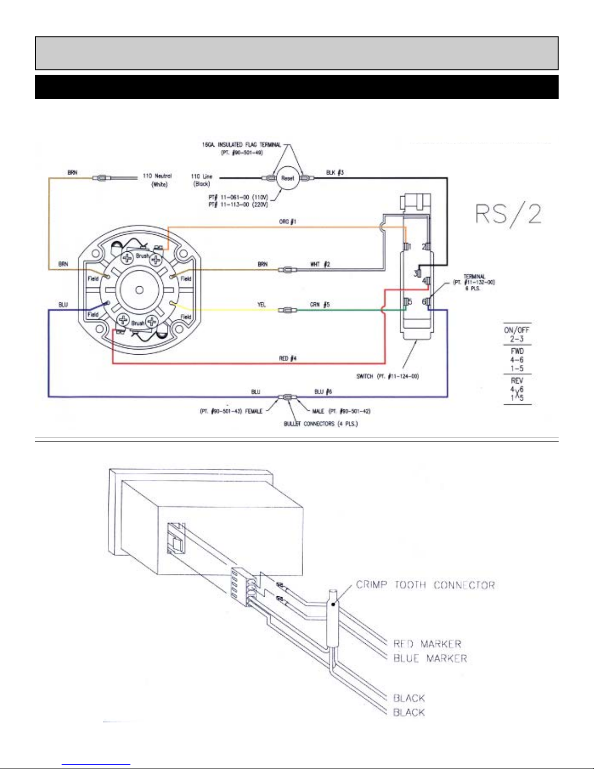
EIBENSTOCK MOTOR SWITCH SCHEMATIC
REVOLUTION COUNTER CONNECTION
18
Page 19
RS-2
SECTION IV CHARTS & SCHEMATIC
Torque Charts
19
Page 20

RS-2
Section V
Bill of Materials
20
Page 21

RS-2
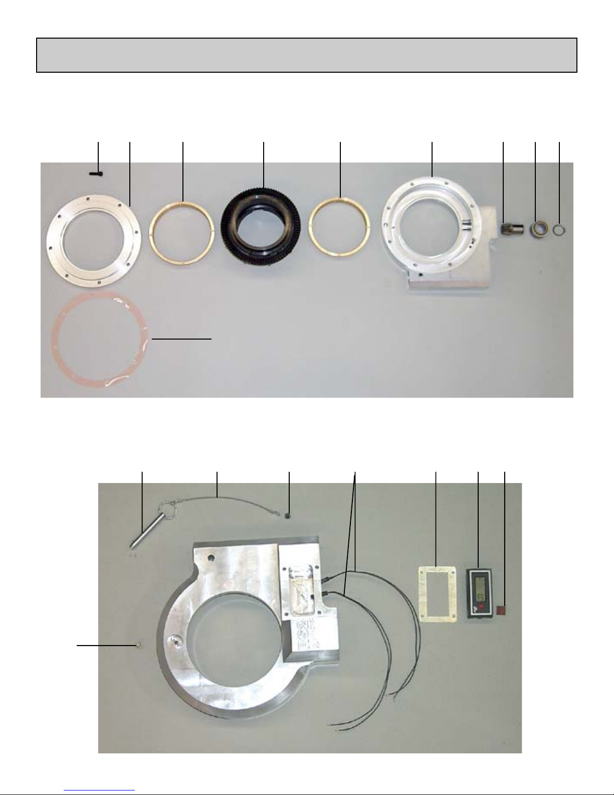
Main Head Assembly
BOM 78-000-01
Ref. Part No. Qty. Description
001 78-001-00 1 HOUSING
002 78-002-00 1 RETAINER, BEARING
005 78-005-00 1 HUB, DRIVE
006 78-006-00 1 BUSHING, LOWER
007 78-007-00 1 BUSHING, UPPER
015 78-015-02 1 .002" SHIM
015 78-015-04 1 .004" SHIM
039 56-039-00 1 SNAP RING #5101-98*
040 56-040-00 1 BEARING,”INA”*
NS 63-026-00 10 MAGNET
Fastners
1 90-060-10 8 SHCS,5/16-18 X 1
009 66-009-00 1 GEAR, PINION
Revolution Counter Assembly
BOM 78-000-01
Ref. Part No. Qty. Description
008 78-008-00 1 PLATE, MOUNTING
145 11-145-00 2 SENSOR, POSITION
045 58-045-00 1 COUNTER,REVOLUTION
121 62-121-00 1 LANYARD 6"LG
Fastners
1 90-501-46 1 CONNECTOR, MOLEX
2 90-042-03 4 BHCS,10-24 X 3/8
3 90-079-20 1 PIN,FAST3/8 X 2 1/8
4 90-500-05 1 GRSE.FTG,1/4-28 STR
21
Page 22
RS-2
Main Head Assembly
BOM 78-000-01
1 002 006 005 007 001 009 040 039
015
Revolution Counter Assembly
BOM 78-000-01
3
4
121 2 145 008 045 1
22
Page 23

RS-2
Hydraulic Drive Assembly
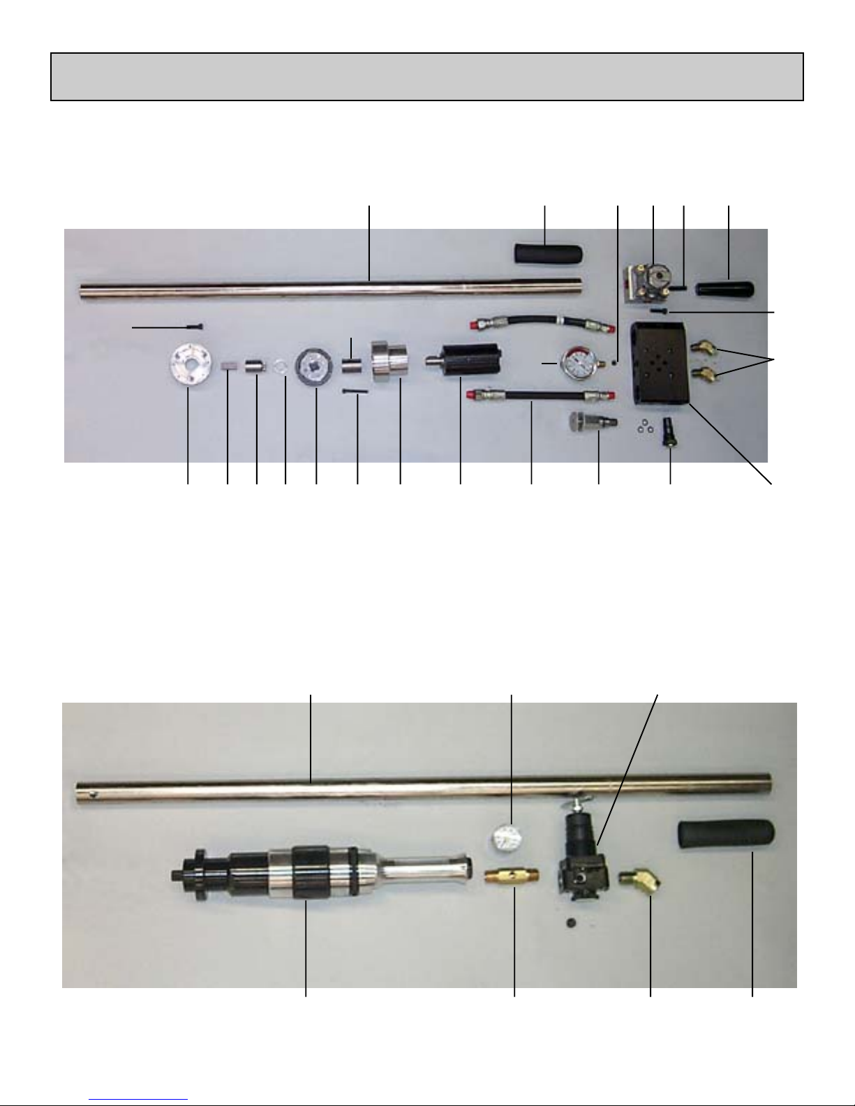
BOM 78-000-04
Ref. Part No. Qty. Description
010 78-010-00 1 PLATE, ADAPTER
199 02-199-00 1 KEY, DRIVE
013 78-013-00 1 HOUSING, GEARSET-HYD
014 78-014-00 1 COUPLING, INPUT
NS 11-044-00 1 HANDLE EXTENSION
054 11-054-00 2 GRIP, RUBBER
081 11-081-00 1 BAR, HANDLE - AIR
088 11-088-00 2 HOSE, HYDRAULIC
089 11-089-00 1 HANDLE, TAPERED*
092 11-092-00 1 MOTOR*
103 11-103-00 1 GEAR, PLANETARY*
110 11-110-00 1 GAUGE, TORQUE*
141 11-141-00 1 MANIFOLD*
142 11-142-00 1 REGULATOR, PRI.FLOW
116 05-116-00 1 VALVE, RELIEF*
151 05-151-00 1 VALVE, REVERSING*
048 70-048-00 1 RING, SPACER
NS 78-MAN-01 1 MANUAL, RS2
NS 78-016-00 1 CASE, STORAGE
011 78-011-00 1 SHAFT, OUTPUT
Fastners
1 90-020-15 7 SHCS, 8-32 X 1 1/2
2 90-028-01 6 SHPP,1/8 DRYSEAL
3 90-050-67 5 SHCS,1/4-28X1-3/4
4 90-060-08 3 SHCS,5/16-18 X 7/8
5 90-075-65 1 SSS, 3/8-16 X 1-1/2
6 90-178-01 2 ST.EL 3/8NPT-45
Ref. Part No. Qty. Description
NS 11-044-00 1 HANDLE EXTENSION
054 11-054-00 2 GRIP, RUBBER
081 11-081-00 1 BAR, HANDLE - AIR
093 11-093-01 1 REGULATOR*
093 11-093-02 1 GAUGE,1.5"X1/8"PIPE
137 11-137-00 1 NIPPLE
017 78-017-00 1 MOTOR, PNEUMATIC
NS 78-016-00 1 CASE, STORAGE
NS 78-MAN-01 1 MANUAL, RS2
Fastners
1 90-098-62 1 ST.EL,1/2-45DEG
N/S 90-060-10 6 SHCS 5/16-18X1”
Pneumatic Drive Assembly
BOM 78-000-03
23
Page 24
RS-2
Hydraulic Drive Assembly
BOM 78-000-04
4
010 199 011
081 054
014
092 088 116 142048 103 1 013
110
089 5151 2
3
6
141
Pneumatic Drive Assembly
BOM 78-000-03
017
093-02081
137
093-01
1
054
24
Page 25

RS-2
Electric Drive Assembly
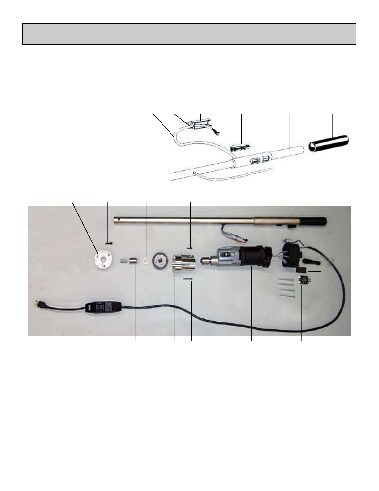
BOM 78-000-01
Ref. Part No. Qty. Description
009 78-009-01 1 HOUSING, GEARSET
010 78-010-00 1 PLATE, ADAPTER
011 78-011-00 1 SHAFT, OUTPUT
199 02-199-00 1 KEY,DRIVE
NS 11-044-00 1 HANDLE EXTENSION
054 11-054-00 2 GRIP, RUBBER
122 11-122-00 1 WELDMENT,SWITCH HNDL
123 11-123-00 1 HOUSING, SWITCH
124 11-124-00 1 SWITCH, MODIFIED
131 11-131-00 22” WIRE,6COND.16GA.POLY
NS 11-132-00 6 TERMINAL, END
NS 11-133-00 1 GROMMET, RUBBER
NS 11-134-00 1 PLUG, #4 RUBBER
NS 11-135-00 1 PLUG, #6 RUBBER
103 11-103-00 1 GEAR, PLANETARY*
018 78-018-00 1 MOTOR
020 78-020-00 1 BLANKING PLATE
041 11-041-00 1 INTERRUPTER,CIRCUIT
061 11-061-00 1 BUTTON, RESET
NS 11-069-00 1 LABEL, GFI RESET
048 70-048-00 1 RING, SPACER
NS 78-MAN-01 1 MANUAL, RS2
NS 78-016-00 1 CASE, STORAGE
Fastners
1 90-042-06 2 BHCS,10-32 X 3/8
NS 90-501-42 4 TERM,16GA.BULLET-M
NS 90-501-49 2 1/4 FLAG, INSULATED
2 90-020-15 8 SHCS,8-32 X 1 1/2
3 90-050-08 1 SHCS,1/4-20 X 7/8
4 90-060-08 3 SHCS,5/16-18 X 7/8
25
Page 26
RS-2
Electric Drive Assembly
BOM 78-000-01
131
199 4010
3 103048
122 0541241231
011
26
018041 2009
061
020
Page 27

RS-2
Universal Handwheel
Ref. Part No. Qty. Description
36 09-036-00 1 HUB, UNIVERSAL HANDWHEEL
37 09-037-01 3 CLAMP, STRADDLE
38 09-038-01 3 ARM, SHORT TORQUE
38 09-038-02 3 ARM, MEDIUM TORQUE
38 09-038-03 3 ARM, LONG TORQUE
48 09-048-00 2 EYE BOLT
61 09-061-00 4 FINGER, HANDWHEEL DRIVE
99 90-099-01 3 SCREW, 1/2-13 X 2 SQ HD
NS 90-050-10 8 SHCS, 1/4-20 X 1
NS 90-056-10 2 PIN, DOWEL 1/4 X 1
NS 90-065-01 2 NUT, HEX 5/16-18
NS 90-065-52 2 WASHER, 5/16 FLAT
NS 90-073-12 3 FHCS, 3/8-16 X 1-1/4
NS 90-075-01 3 NUT, HEX 3/8-1/6
1” Inch Drive Adaptor
Ref. Part No. Qty. Description
18 09-018-00 1 1” DRIVE ADAPTOR
NS 90-050-06 2 SHCS, 1/4-20 X 5/8”
Handwheel Adaptor Plate
Ref. Part No. Qty. Description
6 09-006-00 4 FINGER, DRIVE
40 09-040-00 1 PLATE, HANDWHEEL DRIVE
NS 90-050-06 8 SHCS, 1/4-20 X 5/8
NS 90-079-20 4 PIN, FOAST 3/8 X 2-1/8
NS 90-900-11 4 BOLT, 1-3/8 X 2-3/16
27
Page 28

RS-2
1” Inch Drive Adaptor
Handwheel Adaptor Plate
Universal Handwheel
28
Page 29

RS-2
Bill of Material
RS-2
Accessories
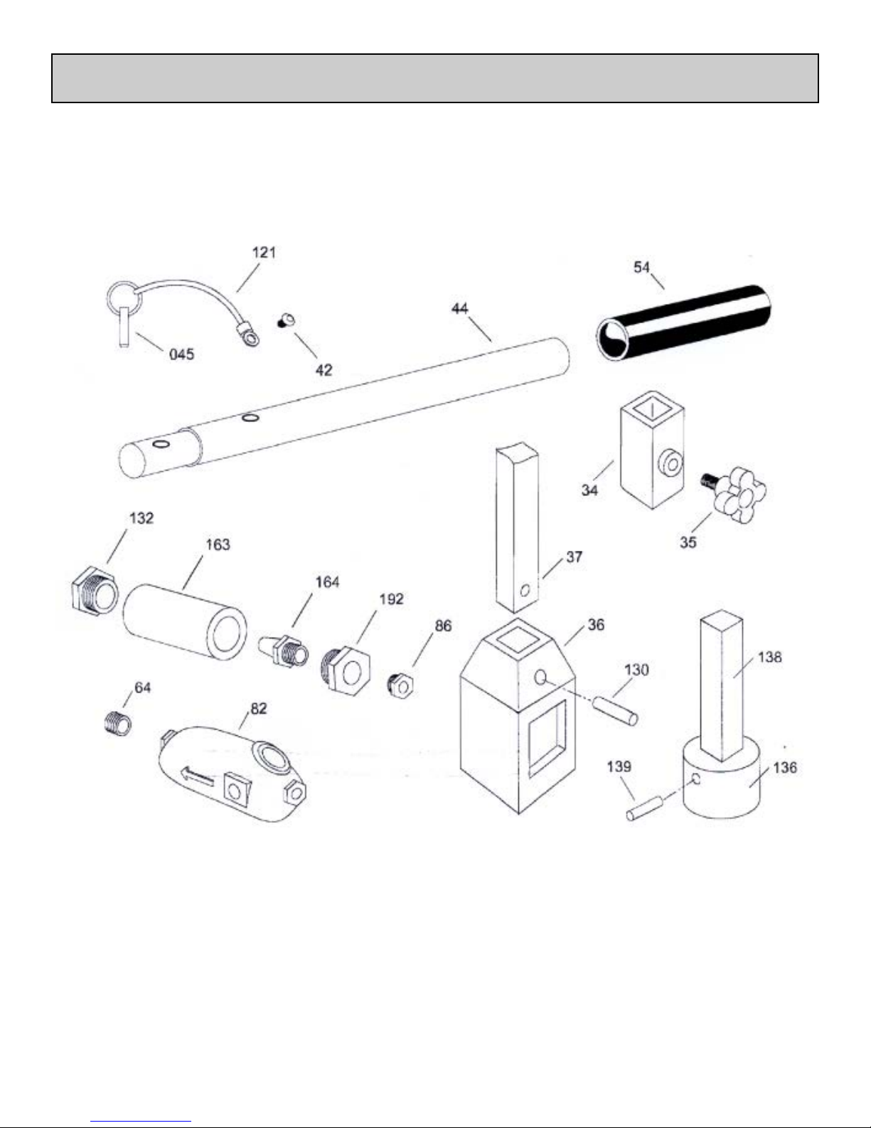
REF PART NO QTY DESCRIPTION
34 05-034-00 1 STOP/COUPLING COLLAR
35 05-035-00 1
36 05-036-00 1 2” SOCKET
37 05-037-00 1 8 FT. LONG KEY
42 90-042-00 1 BHCS, 10-32 x 1/4”
44 11-044-00 1 EXTENSION, HANDLE ASSY
45 11-045-00 1 PIN, QUICK RELEASE
54 11-054-00 1 GRIP RUBBER
82 05-082-00 1 AIR LINE OILER ASSY
64 90-098-01 1 1/2” CLOSE NIPPLE LP.
86 90-098-10 1 BUSHING, RED 1/2 x 3/4
130 90-076-75 1 3/8 X 2-1/2 ROLL PIN
132 90-218-00 1 3/4 X 1-1/4 GALV BUSHING
136 05-136-00 1 15/16 DRIVE SOCKET
138 05-138-00 1 DRIVE KEY
12 62-121-00 1 LANYARD 6.0
139 90-056-70 1 1/4 X 2 ROLL PIN
163 02-163-00 1 FILTER BODY
164 02-164-00 1 FILTER ELEMENT
LOCKING SCREW
192 02-192-00 1 END PLUG
N/S 05-061-01 1 6FT.X1/2HOSEWHIP
N/S 05-403-00 1 4 FT. VALVE KEY EXT.
N/S 02-401 -00 1 H.D. WORM GEAR OIL/QT
N/S 02-402-00 1 AIR MOTOR OIL/i GALLON
N/S 02-403-00 1 ANTI-FREEZE/1 GALLON
N/S 03-404-00 1 45 FT 1/2 HYD HOSE ASSY
29
Page 30
RS-2
30
Page 31
CLECO AIR MOTOR
RS-2
31
Page 32
CLECO AIR MOTOR
RS-2
32
Page 33
CLECO AIR MOTOR
RS-2
33
Page 34

RS-2
E.H. Wachs Water Utility Products
600 Knightsbridge Parkway
Lincolnshire, Illinois 60069 USA
ORDERING INFORMATION
To place an order or to get more detailed information on any E.H. Wachs products, call us at:
1-800-323-8185.
ORDERING REPLACEMENT PARTS
Please use parts list provided in manual. Have part description and part number of required replacement
part or parts to help expedite order and insure proper parts are being ordered.
REPAIR INFORMATION
Please call E.H. Wachs Company prior to returning any equipment for repair. We will advise you of shipping
and handling. Please enclose with equipment to be repaired your name, address, phone number and a brief
description of problem or work to be done or estimated.
All repair work done at our plant will be estimated and the customer advised of cost and time required to
complete repair.
WARRANTY INFORMATION
Enclosed with the manual is a warranty card. Please fill out the registration card and return to E.H. Wachs.
Retain the owners registration record and warranty card for your information.
RETURN GOODS ADDRESS
E.H. Wachs Company
100 Shepard Street
Wheeling, Illinois 60090
Call or Write:
E.H. Wachs Company
100 Shepard Street
Wheeling, Illinois 60090
847-537-8800
FAX: 847-520-1147 • 847-520-1168
Toll-Free: 1-800-323-8185
www.ehwachs.com
PIPE & VALVE
MAINTENANCE PRODUCTS
Mod. S/N:
Enter your machine’s serial number here for proper
record keeping and ordering reference.
34
Page 35

Page 36

600 Knightsbridge Parkway • Lincolnshire, IL 60069
847-537-8800 • www.ehwachs.com
 Loading...