

E.H. Wachs
600 Knightsbridge Parkway
Lincolnshire, IL 60069
www.ehwachs.com
HPU-20 Hydraulic Power Unit
User’s Manual
E.H. Wachs Part No. 14-MAN-35
Revision 0, June 2016
IMPORTANT: Read this manual carefully
before starting and operating the power unit.
Copyright © 2016 E.H. Wachs. All rights reserved.
This manual may not be reproduced in whole or in part
without the written consent of E.H. Wachs.


Table of Contents
Table of Contents
Chapter 1: About the HPU-20 . . . . . . . . . . . . . . . . . . . . . . . . . . . . . . . . . . . . . . . . . . . . . . . . . . 1
Features . . . . . . . . . . . . . . . . . . . . . . . . . . . . . . . . . . . . . . . . . . . . . . . . . . . . . . . . . . . . . . . . . . . . . 1
Specifications . . . . . . . . . . . . . . . . . . . . . . . . . . . . . . . . . . . . . . . . . . . . . . . . . . . . . . . . . . . . . . . . . 5
Chapter 2: Safety . . . . . . . . . . . . . . . . . . . . . . . . . . . . . . . . . . . . . . . . . . . . . . . . . . . . . . . . . . . . . 7
Operator Safety . . . . . . . . . . . . . . . . . . . . . . . . . . . . . . . . . . . . . . . . . . . . . . . . . . . . . . . . . . . . . . . 7
Safety Symbols . . . . . . . . . . . . . . . . . . . . . . . . . . . . . . . . . . . . . . . . . . . . . . . . . . . . . . . . . . . . 8
Protective Equipment Requirements . . . . . . . . . . . . . . . . . . . . . . . . . . . . . . . . . . . . . . . . . . . . 9
Safety Procedures . . . . . . . . . . . . . . . . . . . . . . . . . . . . . . . . . . . . . . . . . . . . . . . . . . . . . . . . . . . 9
Safety Labels . . . . . . . . . . . . . . . . . . . . . . . . . . . . . . . . . . . . . . . . . . . . . . . . . . . . . . . . . . . . . . . . 11
Chapter 3: Using the HPU-20 . . . . . . . . . . . . . . . . . . . . . . . . . . . . . . . . . . . . . . . . . . . . . . . . . . 13
Lifting and Moving the HPU . . . . . . . . . . . . . . . . . . . . . . . . . . . . . . . . . . . . . . . . . . . . . . . . . . . . 13
Set-Up Instructions . . . . . . . . . . . . . . . . . . . . . . . . . . . . . . . . . . . . . . . . . . . . . . . . . . . . . . . . . . . 14
Fill the Hydraulic Reservoir . . . . . . . . . . . . . . . . . . . . . . . . . . . . . . . . . . . . . . . . . . . . . . . . . . 14
Connect Power . . . . . . . . . . . . . . . . . . . . . . . . . . . . . . . . . . . . . . . . . . . . . . . . . . . . . . . . . . . . 15
Connect Hydraulic Hoses . . . . . . . . . . . . . . . . . . . . . . . . . . . . . . . . . . . . . . . . . . . . . . . . . . . 16
Operating Instructions . . . . . . . . . . . . . . . . . . . . . . . . . . . . . . . . . . . . . . . . . . . . . . . . . . . . . . . . . 17
Operating Notes . . . . . . . . . . . . . . . . . . . . . . . . . . . . . . . . . . . . . . . . . . . . . . . . . . . . . . . . . . . 19
Cautions . . . . . . . . . . . . . . . . . . . . . . . . . . . . . . . . . . . . . . . . . . . . . . . . . . . . . . . . . . . . . . . . . 19
Maintenance . . . . . . . . . . . . . . . . . . . . . . . . . . . . . . . . . . . . . . . . . . . . . . . . . . . . . . . . . . . . . . . . . 19
Troubleshooting . . . . . . . . . . . . . . . . . . . . . . . . . . . . . . . . . . . . . . . . . . . . . . . . . . . . . . . . . . . . . . 21
Hydraulic . . . . . . . . . . . . . . . . . . . . . . . . . . . . . . . . . . . . . . . . . . . . . . . . . . . . . . . . . . . . . . . . 21
Electrical . . . . . . . . . . . . . . . . . . . . . . . . . . . . . . . . . . . . . . . . . . . . . . . . . . . . . . . . . . . . . . . . 22
Schematic . . . . . . . . . . . . . . . . . . . . . . . . . . . . . . . . . . . . . . . . . . . . . . . . . . . . . . . . . . . . . . . . 23
Chapter 4: Ordering Information . . . . . . . . . . . . . . . . . . . . . . . . . . . . . . . . . . . . . . . . . . . . . . 25
Ordering Replacement Parts . . . . . . . . . . . . . . . . . . . . . . . . . . . . . . . . . . . . . . . . . . . . . . . . . . . . 25
Repair Information . . . . . . . . . . . . . . . . . . . . . . . . . . . . . . . . . . . . . . . . . . . . . . . . . . . . . . . . . . . . 25
Warranty Information . . . . . . . . . . . . . . . . . . . . . . . . . . . . . . . . . . . . . . . . . . . . . . . . . . . . . . . . . 26
Return Goods Address . . . . . . . . . . . . . . . . . . . . . . . . . . . . . . . . . . . . . . . . . . . . . . . . . . . . . . . . . 26
E.H. Wachs Part No. 14-MAN-35, Rev. 0-0616 i

HPU-20 Hydraulic Power Unit
ii Part No. 14-MAN-35, Rev. 0-0616 E.H. Wachs

Chapter 1
About the HPU-20
The Wachs HPU-20 hydraulic power unit provides 18 gpm
hydraulic flow at a maximum pressure of 1800 psi (57 l/
min at 124 bar). The unit is powered by a 20 HP electric
motor.
Before operating the unit, read and understand the instructions in this manual.
FEATURES
The HPU-20 hydraulic power unit includes the following
standard features:
• 20 HP electric motor (380-460 V, 50/60 Hz).
• Line reactor to suppress noise.
• Over Temp/Low Oil warning light.
• Pendant with controls for power on/off, speed (flow),
flow direction, and emergency stop.
• Removable mobile base with non-marring casters.
• Five-point lifting system.
• 10 micron hydraulic oil filter.
• Heat exchanger with digital readout.
• Helical cut, ultra quiet hydraulic gear pump.
• Powder coat finish.
The following figures illustrate the features of the HPU-20
power unit.
E.H. Wachs Part No. 14-MAN-35, Rev. 0-0616 1
HPU-20 Hydraulic Power Unit
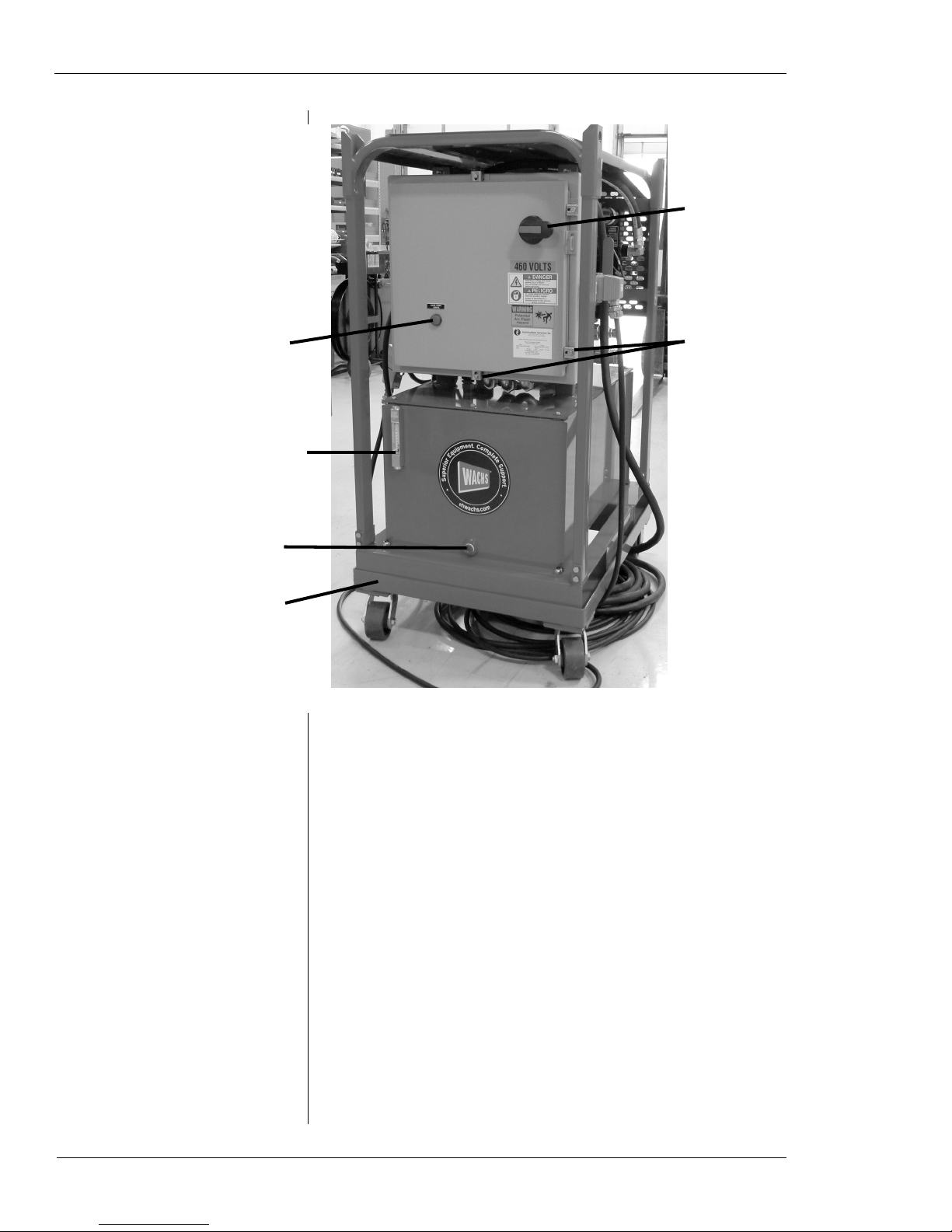
Main power/
panel
disconnect
Over temp/
low oil
warning light
Reservoir oil
temperature
and level gauge
Reservoir oil
drain plug
Mobile base
(removable)
Panel lock
fasteners (4)
Figure 1-1. The photo shows the front of the HPU-20.
2 Part No. 14-MAN-35, Rev. 0-0616 E.H. Wachs
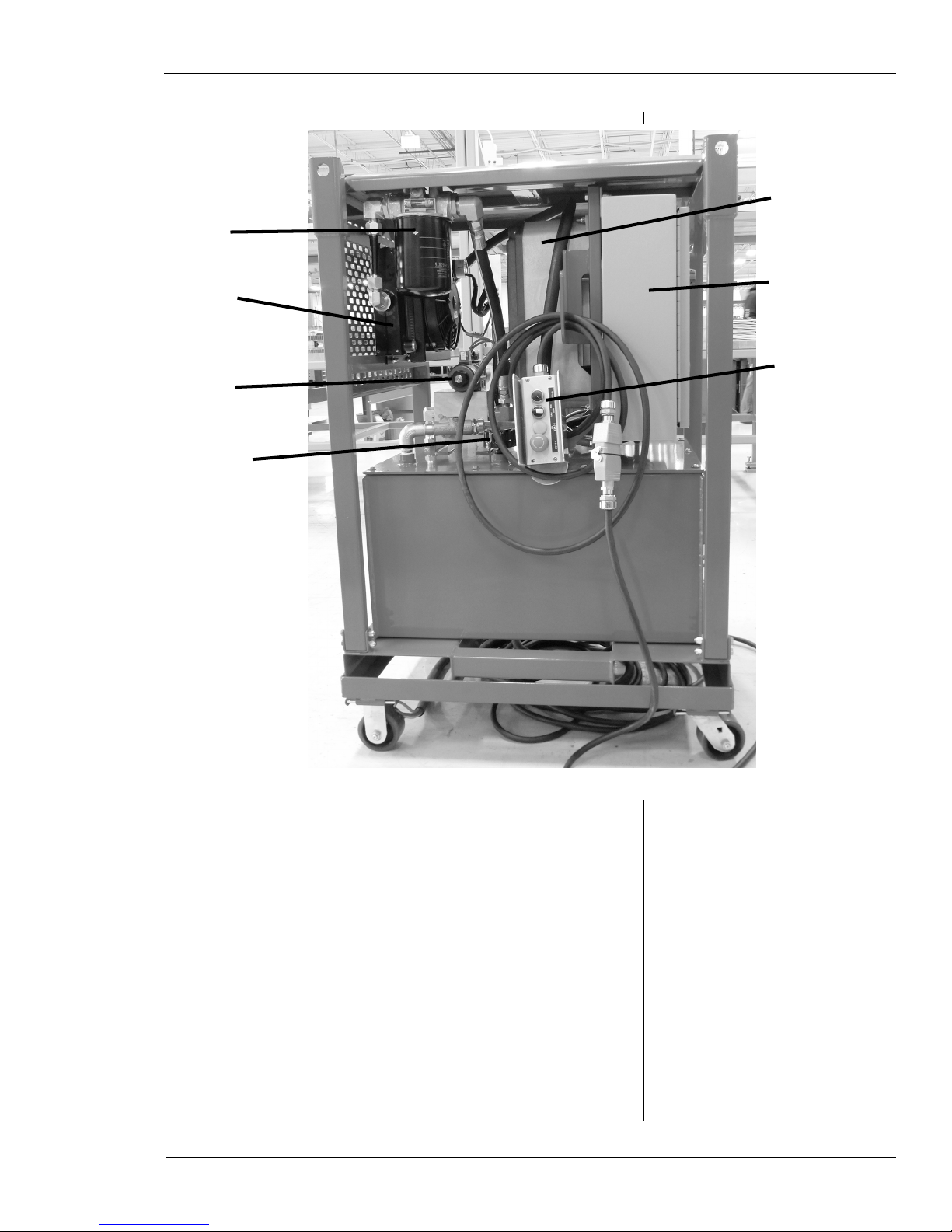
Hydraulic oil
filter
Variable
frequency
drive
Hydraulic oil
cooler
Hydraulic
valve
Oil fill/
breather
Electrical
panel
Operating
pendant
Figure 1-2. The photo shows operating features of the
HPU-20.
E.H. Wachs Part No. 14-MAN-35, Rev. 0-0616 3
HPU-20 Hydraulic Power Unit
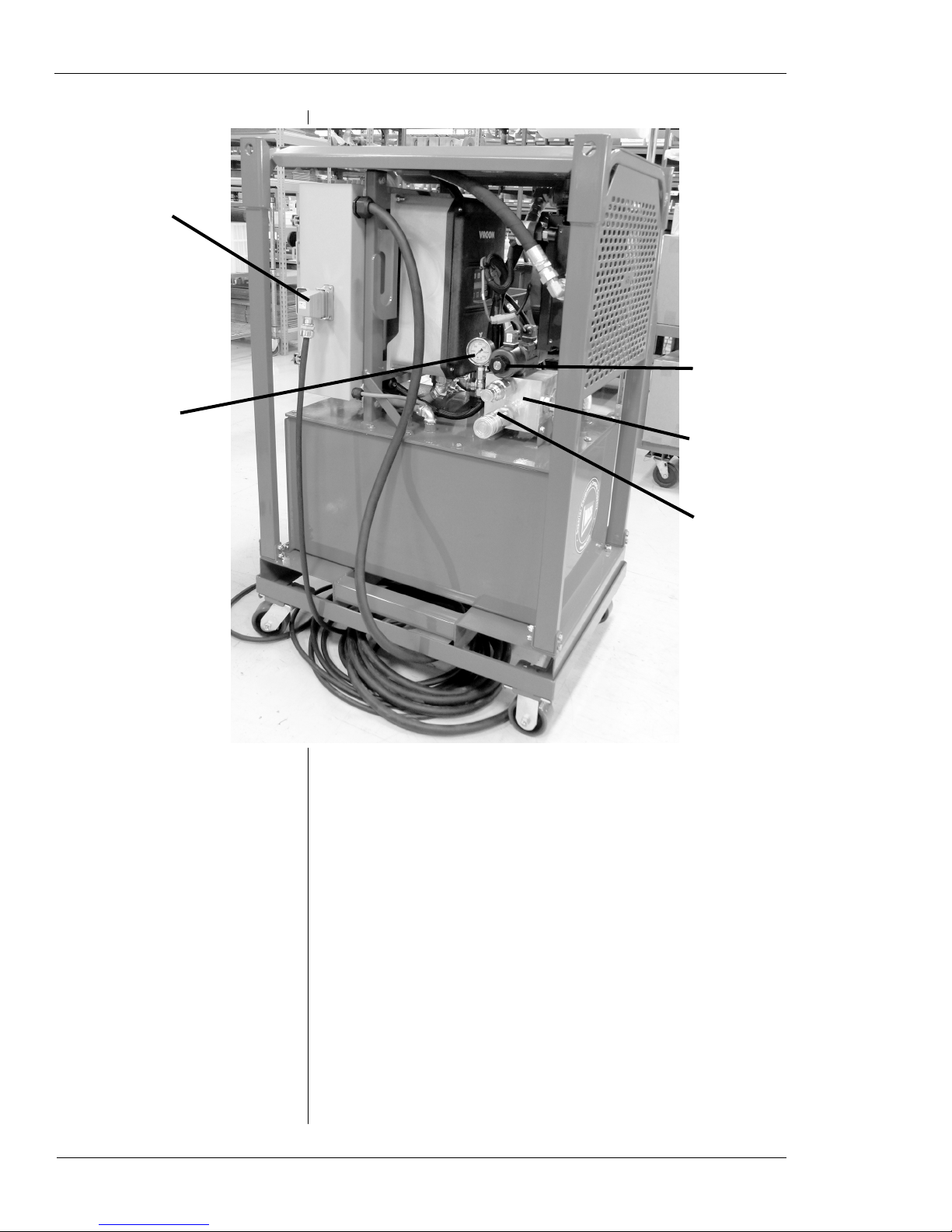
Power
input
Pressure
gauge
Hydraulic
valve
Hydraulic
manifold
Hose
fittings
4 Part No. 14-MAN-35, Rev. 0-0616 E.H. Wachs
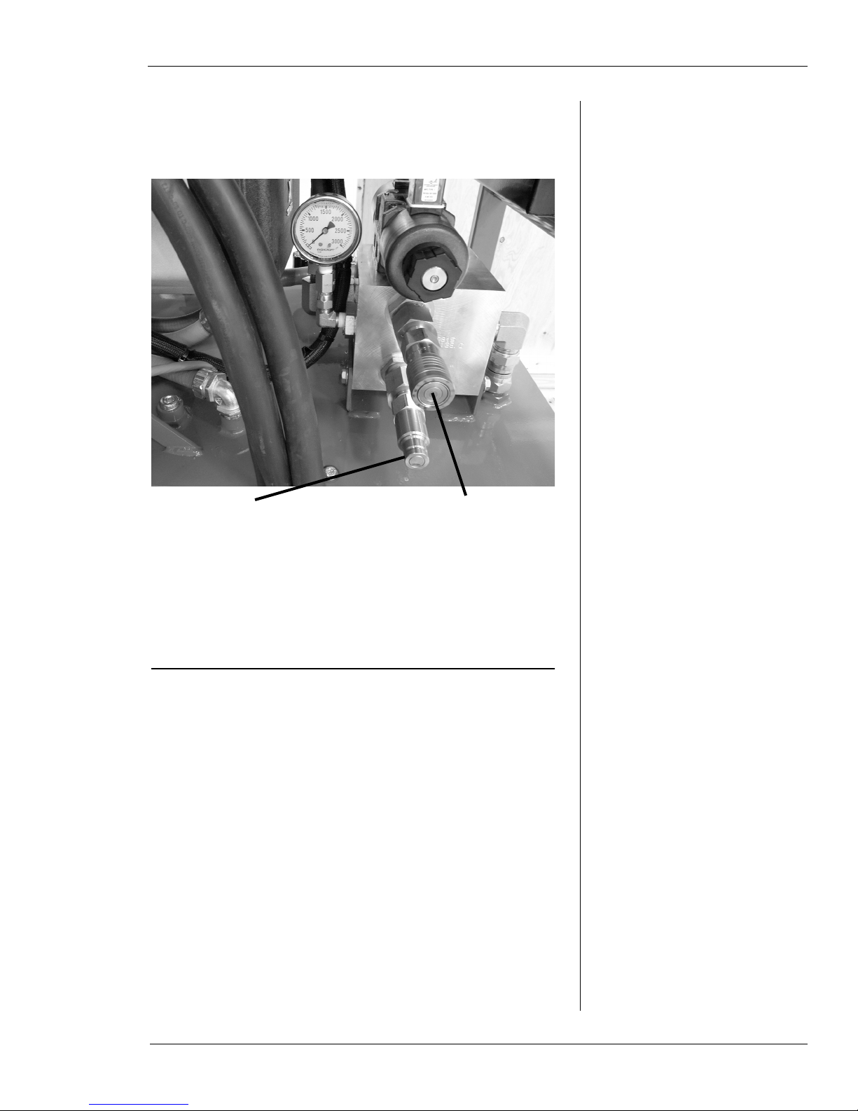
Figure 1-3. The photo shows operating features of the
HPU-20.
Figure 1-4.
Pressure port:
1/2” NPT adapter (part no. 90058-12) and male quick disconnect (part no. 09-026-00)
Return (tank) port:
1/2” NPT adapter (part no. 90058-12) and female quick disconnect (part no. 09-025-00)
Figure 1-5. The drawing identifies the hydraulic fittings on the HPU-20.
SPECIFICATIONS
• Flow: 4-18 gpm @ 1800 psi (15-68 l/min @ 124 bar)
• Pressure: Factory set at 1800 psi (124 bar)
• Dimensions (with base): 34.5” l x 52.5” h x 26” w
(88 cm x 133 cm x 66 cm)
• Weight: 850 lb (386 kg), including oil and mobile base
• Hydraulic Oil Capacity: 30 gallons (114 liters)
• Hydraulic Relief Pressure: 1800 psi (124 bar)
• Current Draw: 30 amps
• Operating Temperature: 110° F (43° C)
• Noise Level: 62 dB at full flow and operation.
E.H. Wachs Part No. 14-MAN-35, Rev. 0-0616 5

HPU-20 Hydraulic Power Unit
6 Part No. 14-MAN-35, Rev. 0-0616 E.H. Wachs

Chapter 2
Safety
Chapter 2, Safety
E.H. Wachs takes great pride in designing and manufacturing safe, high-quality products. We make user safety a top
priority in the design of all our products.
Read this chapter carefully before operating the hydraulic
power unit. It contains important safety instructions and
recommendations.
OPERATOR SAFETY
Follow these guidelines for safe operation of the equipment.
• READ THE OPERATING MANUAL. Make sure
you understand all setup and operating instructions
before you begin.
INSPECT MACHINE AND ACCESSORIES.
•
Before starting the machine, look for loose bolts or
nuts, leaking lubricant, rusted components, and any
other physical conditions that may affect operation.
Properly maintaining the machine can greatly decrease
the chances for injury.
ALWAYS READ PLACARDS AND LABELS. Make
•
sure all placards, labels, and stickers are clearly legible
and in good condition. You can purchase replacement
labels from E.H. Wachs Company.
KEEP CLEAR OF MOVING PARTS. Keep hands,
•
arms, and fingers clear of all rotating or moving parts.
In This Chapter
OPERATOR SAFETY
Look for this symbol throughout the
manual. It indicates
a personal injury
hazard.
E.H. Wachs Part No. 14-MAN-35, Rev. 0-0616 7

HPU-20 Hydraulic Power Unit
Always turn machine off before doing any adjustments
or service.
SECURE LOOSE CLOTHING AND JEWELRY.
•
Secure or remove loose-fitting clothing and jewelry, and
securely bind long hair, to prevent them from getting
caught in moving parts of the machine.
KEEP WORK AREA CLEAR. Keep all clutter and
•
nonessential materials out of the work area. Only people
directly involved with the work being performed should
have access to the area.
Safety Symbols
This icon is displayed with any safety alert that indicates a
personal injury hazard.
WARNING
This safety alert indicates a potentially hazardous situation
that, if not avoided, could result in death or serious injury.
CAUTION
This safety alert, with the personal injury hazard symbol,
indicates a potentially hazardous situation that, if not
avoided, could result in minor or moderate injury.
NOTICE
8 Part No. 14-MAN-35, Rev. 0-0616 E.H. Wachs
This alert indicates a situation that, if not avoided, will
result in damage to the equipment.

IMPORTANT
This alert indicates a situation that, if not avoided, may
result in damage to the equipment.
Protective Equipment Requirements
WARNING
Always wear impact resistant eye protection while operating or working near
this equipment.
For additional information on eye and face protection, refer
to Federal OSHA regulations, 29 Code of Federal Regulations, Section 1910.133., Eye and Face Protection and
American National Standards Institute, ANSI Z87.1, Occu-
pational and Educational Eye and Face Protection. Z87.1 is
available from the American National Standards Institute,
Inc., 1430 Broadway, New York, NY 10018.
Chapter 2, Safety: Operator Safety
CAUTION
Personal hearing protection is recommended when operating or working near
this equipment.
Hearing protectors are required in high noise areas, 85 dBA
or greater. The operation of other tools and equipment in the
area, reflective surfaces, process noises, and resonant structures can increase the noise level in the area. For additional
information on hearing protection, refer to Federal OSHA
regulations, 29 Code of Federal Regulations, Section
1910.95, Occupational Noise Exposure and ANSI S12.6
Hearing Protectors.
Safety Procedures
All safety requirements listed below are those generally
applicable to hydraulically-powered machinery but are not
intended to be an all-inclusive list. They are intended as
guidelines only and will assist in avoiding risk of injury
when followed by qualified, experienced personnel. These
E.H. Wachs Part No. 14-MAN-35, Rev. 0-0616 9
HPU-20 Hydraulic Power Unit
precautions should be included in the comprehensive safety
program for the particular machinery, equipment, plant or
process and overseen by personnel capable of analyzing any
hazards associated with operating and maintaining the
equipment.
WARNING
Many types of
machinery have
parts that may
start moving as soon as the
hydraulic circuit is filled and
pressurized. This could result
in injury to personnel or damage to machinery.
WARNING
Make sure all personnel are clear
from the machinery being operated before
shutting down the HPU.
Return all movable parts of the machinery being oper-
1.
ated to their normal startup condition, if possible,
before starting unit.
Be sure all personnel, product, etc. are clear of
2.
machinery before starting hydraulic unit.
Check to make sure any hydraulic connections which
3.
may have been removed, replaced or disconnected
during shut down have been reconnected securely
before starting hydraulic unit.
Before starting the unit, perform all equipment checks
4.
described at the beginning of the operating instructions.
If there are tools or machinery being operated by the
5.
HPU that may move when hydraulic flow or pressure
are turned off or turned on, block or lock these parts in
position before shutting down the hydraulic unit.
Shut down the hydraulic unit and relieve pressure
6.
from all pressurized accumulators, actuators and lines
before removing, tearing down or performing maintenance on any remotely-located actuators, hoses, filters, valves, piping, etc.
Any personnel observing or working on or adjacent to
7.
hydraulically-powered equipment must never place
themselves in a location or position that could produce
an injury in the event of:
10 Part No. 14-MAN-35, Rev. 0-0616 E.H. Wachs
• a hydraulic line failure either with the unit running or
shut down;
• pump or motor failure or;
• pin-hole leaks in hoses or fittings;
• movement of machine components during normal operation or resulting from a component malfunction or failure.

Chapter 2, Safety: Safety Labels
Do not inspect hoses and fittings for leaks using your
8.
bare hands. A pin-hole leak can inject hydraulic fluid
through the skin, with the potential for serious injury.
Avoid locating equipment in any environment for
9.
which it was not designed and which may create a
dangerous operating condition such as an explosive
atmosphere (e.g., gas, dust), high heat (e.g., molten
metal, furnace), chemicals, extreme moisture, etc.
Avoid bodily contact with hydraulic fluids. Some
10.
hydraulic fluids may irritate or injure the eyes and
skin. Check with your fluid suppliers to obtain this
information.
Use only E.H. Wachs parts and materials when servic-
11.
ing the equipment. Substitute parts or materials could
produce a hazardous operating condition.
When piping your equipment, use only materials of
12.
adequate size and strength to suit the flows and pressures of the system. Consider all safety factors when
selecting the strength of materials to allow for shock
and over-pressure conditions which could occur.
WARNING
The injection of
hydraulic fluid
under the skin can
cause serious injury and
even result in death. If an
injection injury occurs, seek
medical treatment immediately.
SAFETY LABELS
Safety labels on the front panel of the unit indicate the electrical hazards.
• Hazardous voltages can cause severe injury or death.
• An arc flash can cause severe injury or death.
Disconnect power from the HPU before opening the cabinet
or performing any service on it.
E.H. Wachs Part No. 14-MAN-35, Rev. 0-0616 11

HPU-20 Hydraulic Power Unit
Figure 2-1. Labels on the front panel warn of electrical hazards.
12 Part No. 14-MAN-35, Rev. 0-0616 E.H. Wachs

Chapter 3
Using the HPU-20
LIFTING AND MOVING THE HPU
The HPU-20 is supplied with a mobile base on caster
wheels. The base can be removed from the unit.
The bottom of the HPU-20 frame has channels for lifting
with a fork truck.
There are 5 lift points on top of the HPU-20 frame, one at
each corner and one in the center. Attach to these points
when lifting with an overhead crane.
Figure 3-1. Use the lift points on top of the frame.
E.H. Wachs Part No. 14-MAN-35, Rev. 0-0616 13

HPU-20 Hydraulic Power Unit
SET-UP INSTRUCTIONS
The HPU-20 power unit is completely assembled before
delivery. For safe shipping, it is delivered without hydraulic
fluid.
Fill the Hydraulic Reservoir
NOTE: It is extremely important that the pump is not
started until oil is in the system. Power units are shipped
without oil. Operating a pump
without oil, even for a short
time, will result in damage.
Fill the hydraulic reservoir with hydraulic oil. The HPU-20
holds approximately 30 gallons (114 l). Make sure you fill
the reservoir before starting the power unit.
Use an ISO-AW32 (preferred) or ISO-AW46 oil. Oil should
have anti-wear characteristics, excellent rust protection, and
contain additives to protect against foaming.
Hydraulic reservoir cap
14 Part No. 14-MAN-35, Rev. 0-0616 E.H. Wachs
Figure 3-2. Remove the hydraulic reservoir cap and
fill the reservoir with hydraulic oil (approximate
capacity 30 gallons [114 l]).

Figure 3-3. Fill the reservoir to the level indicated on
the oil level/temperature gauge.
Wipe up any spilled oil and replace the cap tightly. Do not
operate the power unit without the cap securely in place.
Connect Power
Connect power to the HPU-20 at the connector on the side
of the electrical panel. The unit can operate on 380-460 V,
50/60 Hz.
The input voltage limit is 380-460 V, +/- 15% (325-530 V).
E.H. Wachs Part No. 14-MAN-35, Rev. 0-0616 15

HPU-20 Hydraulic Power Unit
Figure 3-4. Attach power to the connector on the
electrical panel of the HPU-20.
NOTE: The power unit is factory-set to operate at 1800
psi (124 bar). It is extremely
important that the hoses used
with this unit are rated for
3000 psi (186 bar) or higher
pressure.
Connect Hydraulic Hoses
Connect the hoses to the quick disconnect fittings as shown.
Return
(tank) port
Pressure
port
Figure 3-5. Connect the hydraulic hoses to the fittings
as shown.
16 Part No. 14-MAN-35, Rev. 0-0616 E.H. Wachs

Note: Never connect or disconnect quick couplers when the
HPU is on. Never connect or disconnect quick couplers
when the circuit is under pressure. See the pressure gauge.
OPERATING INSTRUCTIONS
Before starting the power unit, perform the following
checks:
• Make sure the reservoir is filled to the required level
with hydraulic oil.
• Make sure the cabinet door is secured with the panel
lock fasteners.
• Make sure the power cable is securely connected to the
electrical cabinet.
• Make sure the handheld control pendant is connected.
Turn the flow control knob to the OFF position (all the
1.
way counter-clockwise).
Figure 3-6. Turn the main switch on the front of the
cabinet to the ON position.
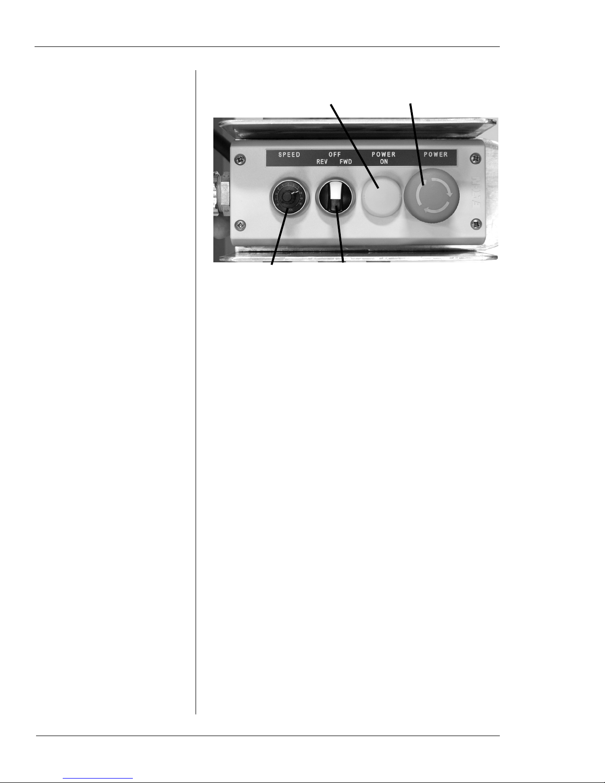
On the handheld pendant, turn the POWER knob
2.
counter-clockwise until the POWER ON indicator
lights up.
E.H. Wachs Part No. 14-MAN-35, Rev. 0-0616 17
HPU-20 Hydraulic Power Unit
POWER ON light indicates
when unit has power.
Turn POWER knob
to start unit.
Turn the SPEED knob
to set the desired flow.
Set the operating direction
to FWD, REV, or OFF.
Figure 3-7. Operate the HPU using the handheld control pendant.
To operate the tool, set the operating direction knob to
3.
the FWD position.
Turn the SPEED knob clockwise to start hydraulic
4.
flow. Adjust the knob for the desired operating speed.
To stop the motor, turn the operating direction knob to
5.
the OFF position. You can leave the SPEED knob at
the same position; this will resume the same speed
when you restart the motor.
Operating the HPU without a hydraulic tool connected
6.
will pump oil over the relief valve, creating heat. If the
unit overheats (above 180° F/82° C), it will shut down
automatically, and the Over Temp/Low Oil indicator
on the panel will light up.
18 Part No. 14-MAN-35, Rev. 0-0616 E.H. Wachs
If the unit gets low on oil, it will shut down automati-
7.
cally, and the Over Temp/Low Oil indicator on the
panel will light up.

Operating Notes
Make sure that the hydraulic circuit is properly plumbed
and appropriate for the available amount of oil from the
unit. A circuit with long hoses or a high-capacity tool could
lower the reservoir level considerably. The power unit must
be plumbed to an open center valve.
If the hydraulic circuit is improperly plumbed, pressure will
build immediately and dump over the relief valve setting,
causing excessive heat.
Cautions
Escaping hydraulic fluid under pressure can have sufficient
force to penetrate skin, causing serious personal injury.
Before disconnecting lines, be sure to relieve all pressure.
Before applying pressure to the system, be sure all connections are tight and that lines and hoses are not damaged.
Fluid escaping from a very small hole can be almost invisible. Use a piece of cardboard or wood rather than hands to
search for suspected leaks.
If injured by escaping fluid, SEE A DOCTOR AT ONCE.
Serious infection or reaction can develop if proper medical
treatment is not administered immediately.
See the safety guidelines in the next chapter.
MAINTENANCE
Every time you use the power unit, inspect all fasteners,
hydraulic hoses, and fittings.
Every time you use the power unit, check the hydraulic oil
level in the reservoir. Check the oil level periodically during
extended use.
Check the condition of the hydraulic fluid, looking for contaminants, dirt, or discoloration. Change the fluid as soon as
it becomes dirty or discolored. It is recommended that you
change the oil every 200 hours of operation.
NOTE: A hydraulic hose failure could be very hazardous;
frequent inspection is important.
E.H. Wachs Part No. 14-MAN-35, Rev. 0-0616 19

HPU-20 Hydraulic Power Unit
The hydraulic system includes a return line filter. Replace
the filter every time you replace the hydraulic fluid. Do not
try to get extended life out of a clogged filter.
Refer to the following chart for hydraulic oil service.
20 Part No. 14-MAN-35, Rev. 0-0616 E.H. Wachs
Figure 3-9. The hydraulic oil drain plug is at the bottom of the oil reservoir, on the front of the unit.

Figure 3-10. Replace the hydraulic oil filter every
time you replace the hydraulic oil.
TROUBLESHOOTING
Hydraulic
Refer to the chart below for hydraulic troubleshooting.
E.H. Wachs Part No. 14-MAN-35, Rev. 0-0616 21

HPU-20 Hydraulic Power Unit
Electrical
Electrical system troubleshooting and repair should be performed by trained and certified electrical staff. Electrical
hazards can result in severe injury or death. Always consult
E.H. Wachs if there are problems that are beyond the scope
of available electrical staff.
Refer to the following notes and chart for electrical system
troubleshooting.
• Make sure there are 3 good legs of power, within the
specified power range.
• Make sure all fuses and circuit breakers are not tripped
or blown.
• Check that the disconnect is turned off.
• Check the connect to the handheld pendant.
• Make sure the Stop button on the pendant is in the “Out”
position.
• Make sure the Variable Frequency Drive is in the
“Remote” setting. See the VFD drive manual.
• Make sure the Over Temp/Oil Level indicator is off.
22 Part No. 14-MAN-35, Rev. 0-0616 E.H. Wachs

Schematic
Refer to the system schematic on the following page for
troubleshooting and repair.
E.H. Wachs Part No. 14-MAN-35, Rev. 0-0616 23


Chapter 4
Ordering Information
To place an order, request service, or get more detailed
information on any E.H. Wachs products, call us at one of
the following numbers:
Chapter 4, Ordering Information
In This Chapter
ORDERING REPLACEMENT
PARTS
REPAIR INFORMATION
U.S. 800-323-8185
International: 847-537-8800
You can also visit our Web site at:
www.ehwachs.com
ORDERING REPLACEMENT PARTS
When ordering parts, refer to the drawings and parts lists on
the following pages. Please provide the part description and
part number for all parts you are ordering.
REPAIR INFORMATION
Please call us for an authorization number before returning
any equipment for repair or factory service. We will advise
you of shipping and handling. When you send the equipment, please include the following information:
• Your name/company name
• Your address
• Your phone number
• A description of the problem or the work to be done.
WARRANTY INFORMATION
RETURN GOODS ADDRESS
E.H. Wachs Part No. 14-MAN-35, Rev. 0-0616 25

HPU-20 Hydraulic Power Unit
Before we perform any repair, we will estimate the work
and inform you of the cost and the time to complete it.
WARRANTY INFORMATION
Enclosed with the manual is a warranty card. Please fill out
the registration card and return to E.H. Wachs. Retain the
owner’s registration record and warranty card for your
information.
RETURN GOODS ADDRESS
Return equipment for repair to the following address.
E.H. Wachs
600 Knightsbridge Parkway
Lincolnshire, Illinois 60069 USA
26 Part No. 14-MAN-35, Rev. 0-0616 E.H. Wachs
 Loading...