

E.H. Wachs
600 Knightsbridge Parkway
Lincolnshire, IL 60069
www.ehwachs.com
EP 424 End Prep Machine
User’s Manual
E.H. Wachs Part No. 81-MAN-00
Rev. 0-0610, June 2010
Revision History:
Original June 2010
Copyright © 2010 E.H. Wachs. All rights reserved.
This manual may not be reproduced in whole or in part
without the written consent of E.H. Wachs.

EP 424 End Prep Machine
Part No. 81-MAN-00, Rev. 0-0610 E.H. Wachs

Table of Contents
Table of Contents
Chapter 1: About This Manual . . . . . . . . . . . . . . . . . . . . . . . . . . . . . . . . . . . . . . . . . . . . . . . . . 1
Purpose of This Manual . . . . . . . . . . . . . . . . . . . . . . . . . . . . . . . . . . . . . . . . . . . . . . . . . . . . . . . . . 1
How to Use The Manual . . . . . . . . . . . . . . . . . . . . . . . . . . . . . . . . . . . . . . . . . . . . . . . . . . . . . . . . 2
Symbols and Warnings . . . . . . . . . . . . . . . . . . . . . . . . . . . . . . . . . . . . . . . . . . . . . . . . . . . . . . . . . 2
Manual Updates and Revision Tracking . . . . . . . . . . . . . . . . . . . . . . . . . . . . . . . . . . . . . . . . . . . . 3
Chapter 2: Safety . . . . . . . . . . . . . . . . . . . . . . . . . . . . . . . . . . . . . . . . . . . . . . . . . . . . . . . . . . . . . 5
Operator Safety . . . . . . . . . . . . . . . . . . . . . . . . . . . . . . . . . . . . . . . . . . . . . . . . . . . . . . . . . . . . . . . 5
Safety Symbols . . . . . . . . . . . . . . . . . . . . . . . . . . . . . . . . . . . . . . . . . . . . . . . . . . . . . . . . . . . . 6
Protective Equipment Requirements . . . . . . . . . . . . . . . . . . . . . . . . . . . . . . . . . . . . . . . . . . . . 7
Safety Labels . . . . . . . . . . . . . . . . . . . . . . . . . . . . . . . . . . . . . . . . . . . . . . . . . . . . . . . . . . . . . . . . . 7
Chapter 3: Introduction to the Equipment . . . . . . . . . . . . . . . . . . . . . . . . . . . . . . . . . . . . . . . 11
Overview of the EP 424 . . . . . . . . . . . . . . . . . . . . . . . . . . . . . . . . . . . . . . . . . . . . . . . . . . . . . . . . 11
Form-Tool Configuration . . . . . . . . . . . . . . . . . . . . . . . . . . . . . . . . . . . . . . . . . . . . . . . . . . . 11
Single-Point Configuration . . . . . . . . . . . . . . . . . . . . . . . . . . . . . . . . . . . . . . . . . . . . . . . . . . 12
EP 424 Components . . . . . . . . . . . . . . . . . . . . . . . . . . . . . . . . . . . . . . . . . . . . . . . . . . . . . . . . 13
Drive Motors . . . . . . . . . . . . . . . . . . . . . . . . . . . . . . . . . . . . . . . . . . . . . . . . . . . . . . . . . . . . . 17
Accessories . . . . . . . . . . . . . . . . . . . . . . . . . . . . . . . . . . . . . . . . . . . . . . . . . . . . . . . . . . . . . . 18
Specifications . . . . . . . . . . . . . . . . . . . . . . . . . . . . . . . . . . . . . . . . . . . . . . . . . . . . . . . . . . . . . . . . 19
Capacities . . . . . . . . . . . . . . . . . . . . . . . . . . . . . . . . . . . . . . . . . . . . . . . . . . . . . . . . . . . . . . . . 19
Dimensions and Weights . . . . . . . . . . . . . . . . . . . . . . . . . . . . . . . . . . . . . . . . . . . . . . . . . . . . 19
Operating Envelope . . . . . . . . . . . . . . . . . . . . . . . . . . . . . . . . . . . . . . . . . . . . . . . . . . . . . . . . . . . 20
Chapter 4: Assembly, Disassembly, and Storage . . . . . . . . . . . . . . . . . . . . . . . . . . . . . . . . . . 29
Packaging . . . . . . . . . . . . . . . . . . . . . . . . . . . . . . . . . . . . . . . . . . . . . . . . . . . . . . . . . . . . . . . . . . . 29
Storage Checklist . . . . . . . . . . . . . . . . . . . . . . . . . . . . . . . . . . . . . . . . . . . . . . . . . . . . . . . . . . . . . 30
Chapter 5: Operating Instructions . . . . . . . . . . . . . . . . . . . . . . . . . . . . . . . . . . . . . . . . . . . . . . 31
Mounting the Mandrel on the Pipe . . . . . . . . . . . . . . . . . . . . . . . . . . . . . . . . . . . . . . . . . . . . . . . 31
Mounting the Universal (Standard) Mandrel . . . . . . . . . . . . . . . . . . . . . . . . . . . . . . . . . . . . . 32
Mounting the Independent Chuck Mandrel . . . . . . . . . . . . . . . . . . . . . . . . . . . . . . . . . . . . . . 37
Using the Drive Motors . . . . . . . . . . . . . . . . . . . . . . . . . . . . . . . . . . . . . . . . . . . . . . . . . . . . . . . . 47
Mounting and Operating the Air Drive . . . . . . . . . . . . . . . . . . . . . . . . . . . . . . . . . . . . . . . . . 47
Mounting and Operating the Hydraulic Drive . . . . . . . . . . . . . . . . . . . . . . . . . . . . . . . . . . . . 50
Form Tool Operation . . . . . . . . . . . . . . . . . . . . . . . . . . . . . . . . . . . . . . . . . . . . . . . . . . . . . . . . . . 53
Planning the Operation . . . . . . . . . . . . . . . . . . . . . . . . . . . . . . . . . . . . . . . . . . . . . . . . . . . . . 54
Operating Envelope . . . . . . . . . . . . . . . . . . . . . . . . . . . . . . . . . . . . . . . . . . . . . . . . . . . . . 54
Selecting Tooling . . . . . . . . . . . . . . . . . . . . . . . . . . . . . . . . . . . . . . . . . . . . . . . . . . . . . . . 54
Adjusting the Tool Holder Positions . . . . . . . . . . . . . . . . . . . . . . . . . . . . . . . . . . . . . . . . 56
Setting Up and Mounting the EP 424 . . . . . . . . . . . . . . . . . . . . . . . . . . . . . . . . . . . . . . . . . . 57
E.H. Wachs Part No. 81-MAN-00, Rev. 0-0610 1

EP 424 End Prep Machine
Assembling the Machine Components . . . . . . . . . . . . . . . . . . . . . . . . . . . . . . . . . . . . . . 57
Removing the Machine from the Workpiece . . . . . . . . . . . . . . . . . . . . . . . . . . . . . . . . . . . . 62
Single Point Operation . . . . . . . . . . . . . . . . . . . . . . . . . . . . . . . . . . . . . . . . . . . . . . . . . . . . . . . . . 63
Installing the Single-Point Kit . . . . . . . . . . . . . . . . . . . . . . . . . . . . . . . . . . . . . . . . . . . . . . . . 63
Planning the Operation . . . . . . . . . . . . . . . . . . . . . . . . . . . . . . . . . . . . . . . . . . . . . . . . . . . . . 68
Operating Envelope . . . . . . . . . . . . . . . . . . . . . . . . . . . . . . . . . . . . . . . . . . . . . . . . . . . . . 68
Selecting Tool Holder . . . . . . . . . . . . . . . . . . . . . . . . . . . . . . . . . . . . . . . . . . . . . . . . . . . 68
Beveling O.D. Set-Back . . . . . . . . . . . . . . . . . . . . . . . . . . . . . . . . . . . . . . . . . . . . . . . . . 68
Setting Up and Mounting the EP 424 . . . . . . . . . . . . . . . . . . . . . . . . . . . . . . . . . . . . . . . . . . 71
Assembling the Machine Components . . . . . . . . . . . . . . . . . . . . . . . . . . . . . . . . . . . . . . 71
Using the Speed Prep Autofeed . . . . . . . . . . . . . . . . . . . . . . . . . . . . . . . . . . . . . . . . . . . . . . . 75
Compound Bevel . . . . . . . . . . . . . . . . . . . . . . . . . . . . . . . . . . . . . . . . . . . . . . . . . . . . . . . 75
Removing the Machine from the Workpiece . . . . . . . . . . . . . . . . . . . . . . . . . . . . . . . . . . . . 77
Removing the Single-Point Kit . . . . . . . . . . . . . . . . . . . . . . . . . . . . . . . . . . . . . . . . . . . . . . . 78
Chapter 6: Routine Maintenance . . . . . . . . . . . . . . . . . . . . . . . . . . . . . . . . . . . . . . . . . . . . . . . 83
Lubrication . . . . . . . . . . . . . . . . . . . . . . . . . . . . . . . . . . . . . . . . . . . . . . . . . . . . . . . . . . . . . . . . . . 83
Main Drive Assembly . . . . . . . . . . . . . . . . . . . . . . . . . . . . . . . . . . . . . . . . . . . . . . . . . . . . . . 83
Felt Wipers . . . . . . . . . . . . . . . . . . . . . . . . . . . . . . . . . . . . . . . . . . . . . . . . . . . . . . . . . . . . . . 85
Single-Point Slide . . . . . . . . . . . . . . . . . . . . . . . . . . . . . . . . . . . . . . . . . . . . . . . . . . . . . . . . . 86
Mandrel . . . . . . . . . . . . . . . . . . . . . . . . . . . . . . . . . . . . . . . . . . . . . . . . . . . . . . . . . . . . . . . . . 86
Drive Motor Lubrication . . . . . . . . . . . . . . . . . . . . . . . . . . . . . . . . . . . . . . . . . . . . . . . . . . . . . . . 87
Chapter 7: Service and Repair . . . . . . . . . . . . . . . . . . . . . . . . . . . . . . . . . . . . . . . . . . . . . . . . . 89
Adjustments . . . . . . . . . . . . . . . . . . . . . . . . . . . . . . . . . . . . . . . . . . . . . . . . . . . . . . . . . . . . . . . . . 89
Adjusting the Single-Point Slide . . . . . . . . . . . . . . . . . . . . . . . . . . . . . . . . . . . . . . . . . . . . . . 89
Tighten the Starwheel Stop Collar . . . . . . . . . . . . . . . . . . . . . . . . . . . . . . . . . . . . . . . . . . 89
Adding/Removing Gib Shims . . . . . . . . . . . . . . . . . . . . . . . . . . . . . . . . . . . . . . . . . . . . . 89
Adjust the Push Plate Set Screws . . . . . . . . . . . . . . . . . . . . . . . . . . . . . . . . . . . . . . . . . . 90
Calibrating the Speed Prep Scale . . . . . . . . . . . . . . . . . . . . . . . . . . . . . . . . . . . . . . . . . . . . . . 91
Air Motor Manual . . . . . . . . . . . . . . . . . . . . . . . . . . . . . . . . . . . . . . . . . . . . . . . . . . . . . . . . . . . . 93
Chapter 8: Parts Lists and Drawings . . . . . . . . . . . . . . . . . . . . . . . . . . . . . . . . . . . . . . . . . . . 95
Chapter 9: Accessories and Spare Parts . . . . . . . . . . . . . . . . . . . . . . . . . . . . . . . . . . . . . . . . . 97
Accessories . . . . . . . . . . . . . . . . . . . . . . . . . . . . . . . . . . . . . . . . . . . . . . . . . . . . . . . . . . . . . . . . . 97
Tooling . . . . . . . . . . . . . . . . . . . . . . . . . . . . . . . . . . . . . . . . . . . . . . . . . . . . . . . . . . . . . . . . . . . . . 98
Chapter 10: Ordering Information . . . . . . . . . . . . . . . . . . . . . . . . . . . . . . . . . . . . . . . . . . . . 101
Ordering Replacement Parts . . . . . . . . . . . . . . . . . . . . . . . . . . . . . . . . . . . . . . . . . . . . . . . . . . . 101
Repair Information . . . . . . . . . . . . . . . . . . . . . . . . . . . . . . . . . . . . . . . . . . . . . . . . . . . . . . . . . . 101
Warranty Information . . . . . . . . . . . . . . . . . . . . . . . . . . . . . . . . . . . . . . . . . . . . . . . . . . . . . . . . 102
Return Goods Address . . . . . . . . . . . . . . . . . . . . . . . . . . . . . . . . . . . . . . . . . . . . . . . . . . . . . . . . 102
2 P art No. 81-MAN-00, Re v. 0-0610 E.H. Wachs

Chapter 1
About This Manual
PURPOSE OF THIS MANUAL
This manual explains how to operate and maintain the
EP 424 end prep machine. It includes instructions for setup, operation, and maintenance. It also contains parts lists,
diagrams, and service information to help you order
replacement parts and perform user-serviceable repairs.
Chapter 1, About This Manual
In This Chapter
PURPOSE OF THIS MANUAL
HOW TO USE THE MANUAL
SYMBOLS AND WARNINGS
MANUAL UPDATES AND
EVISION TRACKING
R
Before operating the EP 424, you should read through this
manual and become familiar with all instructions. At a minimum, make sure you read and understand the following
chapters:
• Chapter 1, About This Manual
• Chapter 2, Safety
• Chapter 3, Introduction to the Equipment
• Chapter 5, Operating Instructions
• Chapter 9, Accessories
If you will be performing service or repairs, make sure you
read and understand these chapters:
• Chapter 1, About This Manual
• Chapter 4, Assembly and Disassembly
• Chapter 6, Routine Maintenance
• Chapter 7, Service and Repair.
You will also want to refer to Chapter 8, Parts Lists and
Drawings.
E.H. Wachs Part No. 81-MAN-00, Rev. 0-0610 1
EP 424 End Prep Machine
WARNING
This is the safety alert symbol. It is used
to alert you to potential personal injury
hazards. Obey all safety messages that
follow this symbol to avoid possible
injury or death.
CAUTION
HOW TO USE THE MANUAL
Throughout this manual, refer
to this column for warnings,
cautions, and notices with
supplementary information.
This manual is organized to help you quickly find the information you need. Each chapter describes a specific topic on
using or maintaining your equipment.
Each page is designed with two columns. This large column
on the inside of the page contains instructions and illustrations. Use these instructions to operate and maintain the
equipment.
The narrower column on the outside contains additional
information such as warnings, special notes, and definitions.
Refer to it for safety notes and other information.
SYMBOLS AND WARNINGS
The following symbols are used throughout this manual to
indicate special notes and warnings. They appear in the outside column of the page, next to the section they refer to.
Make sure you understand what each symbol means, and
follow all instructions for cautions and warnings.
A WARNING alert with the
safety alert symbol indicates
a potentially hazardous situation that could result in seri-
ous injury or death.
A CAUTION alert with the
safety alert symbol indicates
a potentially hazardous situation that could result in
minor or moderate injury.
2 Part No. 81-MAN-00, Rev. 0-0610 E.H. Wachs
Chapter 1, About This Manual: Manual Updates and Revision Tracking
CAUTION
This is the equipment damage alert
symbol. It is used to alert you to potential equipment damage situations.
Obey all messages that follow this symbol to avoid damaging the equipment or
workpiece on which it is operating.
IMPORTANT
NOTE
NOTE
This symbol indicates a user note. Notes
provide additional information to supplement the instructions, or tips for easier
operation.
A CAUTION alert with the
damage alert symbol indicates a situation that will
result in damage to the
equipment.
An IMPORTANT alert with
the damage alert symbol indicates a situation that may
result in damage to the
equipment.
MANUAL UPDATES AND REVISION TRACKING
Occasionally, we will update manuals with improved operation or maintenance procedures, or with corrections if necessary. When a manual is revised, we will update the
revision history on the title page.
You may have factory service or upgrades performed on the
equipment. If this service changes any technical data or
operation and maintenance procedures, we will include a
revised manual when we return the equipment to you.
A NOTE provides supplementary information or operating tips.
Current versions of E.H.
Wachs Company manuals
are also available in PDF format. You can request an
electronic copy of this manual
by emailing customer service
at sales@wachsco.com
.
E.H. Wachs Part No. 81-MAN-00, Rev. 0-0610 3

EP 424 End Prep Machine
4 Part No. 81-MAN-00, Rev. 0-0610 E.H. Wachs

Chapter 2
Safety
E.H. Wachs takes great pride in designing and manufacturing safe, high-quality products. We make user safety a top
priority in the design of all our products.
Chapter 2, Safety
In This Chapter
OPERATOR SAFETY
SAFETY LABELS
Read this chapter carefully before operating the EP 424 end
prep machine. It contains important safety instructions and
recommendations.
OPERATOR SAFETY
Follow these guidelines for safe operation of the equipment.
• READ THE OPERATING MANUAL. Make sure
you understand all setup and operating instructions
before you begin.
• INSPECT MACHINE AND ACCESSORIES.
Before starting the machine, look for loose bolts or
nuts, leaking lubricant, rusted components, and any
other physical conditions that may affect operation.
Properly maintaining the machine can greatly decrease
the chances for injury.
• ALWAYS READ PLACARDS AND LABELS. Make
sure all placards, labels, and stickers are clearly legible
and in good condition. You can purchase replacement
labels from E.H. Wachs Company.
• KEEP CLEAR OF MOVING PARTS.
arms, and fingers clear of all rotating or moving parts.
Keep hands,
Look for this symbol throughout the
manual. It indicates
a personal injury
hazard.
E.H. Wachs Part No. 81-MAN-00, Rev. 0-0610 5
EP 424 End Prep Machine
Always turn machine off before doing any adjustments
or service.
• SECURE LOOSE CLOTHING AND JEWELRY.
Secure or remove loose-fitting clothing and jewelry , and
securely bind long hair, to prevent them from getting
caught in moving parts of the machine.
• KEEP WORK AREA CLEAR. Keep all clutter and
nonessential materials out of the work area. Only people
directly involved with the work being performed should
have access to the area.
Safety Symbols
This icon is displayed with any safety alert that indicates a
personal injury hazard.
WARNING
This safety alert indicates a potentially hazardous situation
that, if not avoided, could result in death or serious injury.
CAUTION
This safety alert, with the personal injury hazard symbol,
indicates a potentially hazardous situation that, if not
avoided, could result in minor or moderate injury.
6 Part No. 81-MAN-00, Rev. 0-0610 E.H. Wachs

Protective Equipment Requirements
Always wear impact resistant eye protection while operating or working near
this equipment.
WARNING
CAUTION
Personal hearing protection is recommended when operating or working near
this tool.
For additional information on eye and face protection, refer
to Federal OSHA regulations, 29 Code of Federal Regulations, Section 1910.133., Eye and Face Protection and
American National Standards Institute, ANSI Z87.1, Occupational and Educational Eye and Face Protection. Z87.1 is
available from the American National Standards Institute,
Inc., 1430 Broadway, New York, NY 10018.
Chapter 2, Safety: Safety Labels
Hearing protectors are required in high noise areas, 85 dBA
or greater . The operation of other tools and equipment in the
area, reflective surfaces, process noises, and resonant structures can increase the noise level in the area. For additional
information on hearing protection, refer to Federal OSHA
regulations, 29 Code of Federal Regulations, Section
1910.95, Occupational Noise Exposure and ANSI S12.6
Hearing Protectors.
SAFETY LABELS
The following safety labels are on the EP 424 machine. If a
label is lost or unreadable, order and attach a replacement.
See ordering instructions in Chapter 10.
E.H. Wachs Part No. 81-MAN-00, Rev. 0-0610 7
EP 424 End Prep Machine
Figure 2-1. Crush hazard safety label (part no. 81165-00).
Figure 2-2. Crush and cut hazard safety label (part
no. 90-401-04).
Figure 2-3. Loud noise hazard safety label, provided
with air drive configurations (part no. 90-401-03).
Figure 2-4. Eye injury hazard label, provided with
hydraulic drive configurations (part no. 90-401-01).
8 Part No. 81-MAN-00, Rev. 0-0610 E.H. Wachs

Figure 2-5. Compressed air pressure safety label
(part no. 90-401-02).
Chapter 2, Safety: Safety Labels
Figure 2-6. Hydraulic pressure safety label (part no.
90-402-01).
E.H. Wachs Part No. 81-MAN-00, Rev. 0-0610 9

EP 424 End Prep Machine
10 Part No. 81-MAN-00, Rev. 0-0610 E.H. Wachs

Chapter 3
Introduction to the
Equipment
OVERVIEW OF THE EP 424
Chapter 3, Introduction to the Equipment
In This Chapter
OVERVIEW OF THE EP 424
S
PECIFICATIONS
The EP 424 is an I.D. (inside diameter) mounted end prep
machine for facing, beveling, counterboring, and J-prepping pipes and flanges. It can be used for pipes from 4-24
inches O.D., with wall thicknesses up to 1.6” (41 mm)
using form tools, or 6.5” (165 mm) with single-point operation.
The EP 424 is provided in 4 configurations:
• Form tool machine with air drive, part no. 81-000-01
• Form tool machine with hydraulic drive, part no. 81000-02
• Single-point machine with air drive, part no. 81-000-03
• Single-point machine with hydraulic drive, part no. 81000-04.
Form tool operation is quick to set up and easy to perform
on pipe walls up to schedule 160 (1.6” on 16” pipe). For
heavier wall pipe up to 6.5” wall thickness, the single-point
kit allows you to perform any bevel profile.
OPERATING ENVELOPE
Form-Tool Configuration
The form tool configurations have a rotating tool head with
3 tool holders, for performing up to 3 simultaneous opera-
E.H. Wachs Part No. 81-MAN-00, Rev. 0-0610 11
EP 424 End Prep Machine
tions. Tooling is available for facing, single-angle beveling,
compound beveling, counterboring,
The form tool configuration will perform end prepping (facing, beveling, J-prepping, and counterboring), with the
operator manually feeding the tool head.
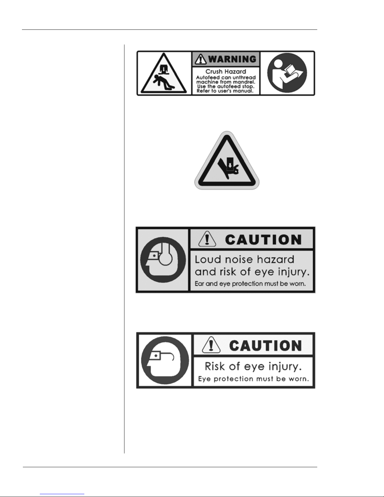
Figure 3-1. The photo shows the form tool configuration of the machine with the standard self-centering
mandrel.
Single-Point Configuration
The single-point machine is provided with a tool slide that
feeds the tool radially across the face of the pipe or flange.
The slide is driven by a starwheel that engages trips on a
ring mounted to the machine housing. Bevels are performed
using the Speed Prep auto-feed system, which automatically
feeds the machine axially as it cuts.
The single-point machine will perform facing or beveling of
thick-walled pipes and flanges.
12 Part No. 81-MAN-00, Rev. 0-0610 E.H. Wachs
Chapter 3, Introduction to the Equipment: Overview of the EP 424
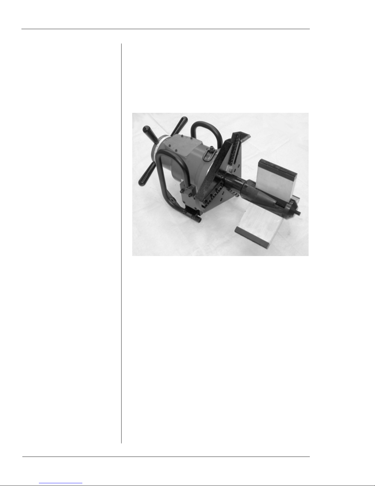
Figure 3-2. The photo shows the single-point configuration of the EP 424.
EP 424 Components
The following components are provided with the form tool
configuration of the EP 424:
• main drive assembly with lifting attachments
• feed assembly
• rotating tool head
• standard self-centering mandrel
• drive motor (air or hydraulic)
• hand tool set
The single-point configuration includes the following additional components:
E.H. Wachs Part No. 81-MAN-00, Rev. 0-0610 13
EP 424 End Prep Machine
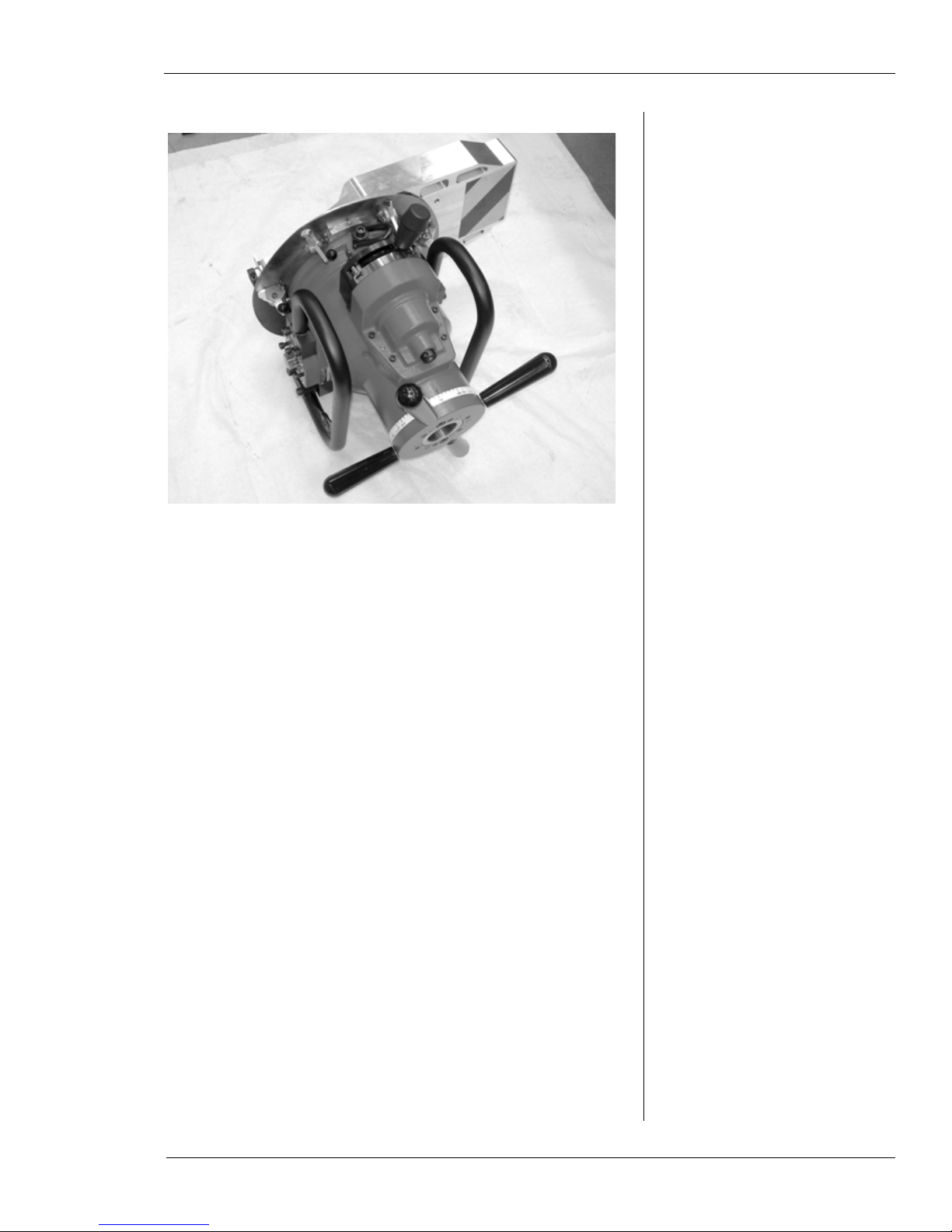
StarwheelFeed screws
Male tool slide
Tool holder
Feed gauge
• single-point slide
Figure 3-3. The single-point slide feeds the tool radially across the pipe face. It is driven along a feed
screw by a starwheel.
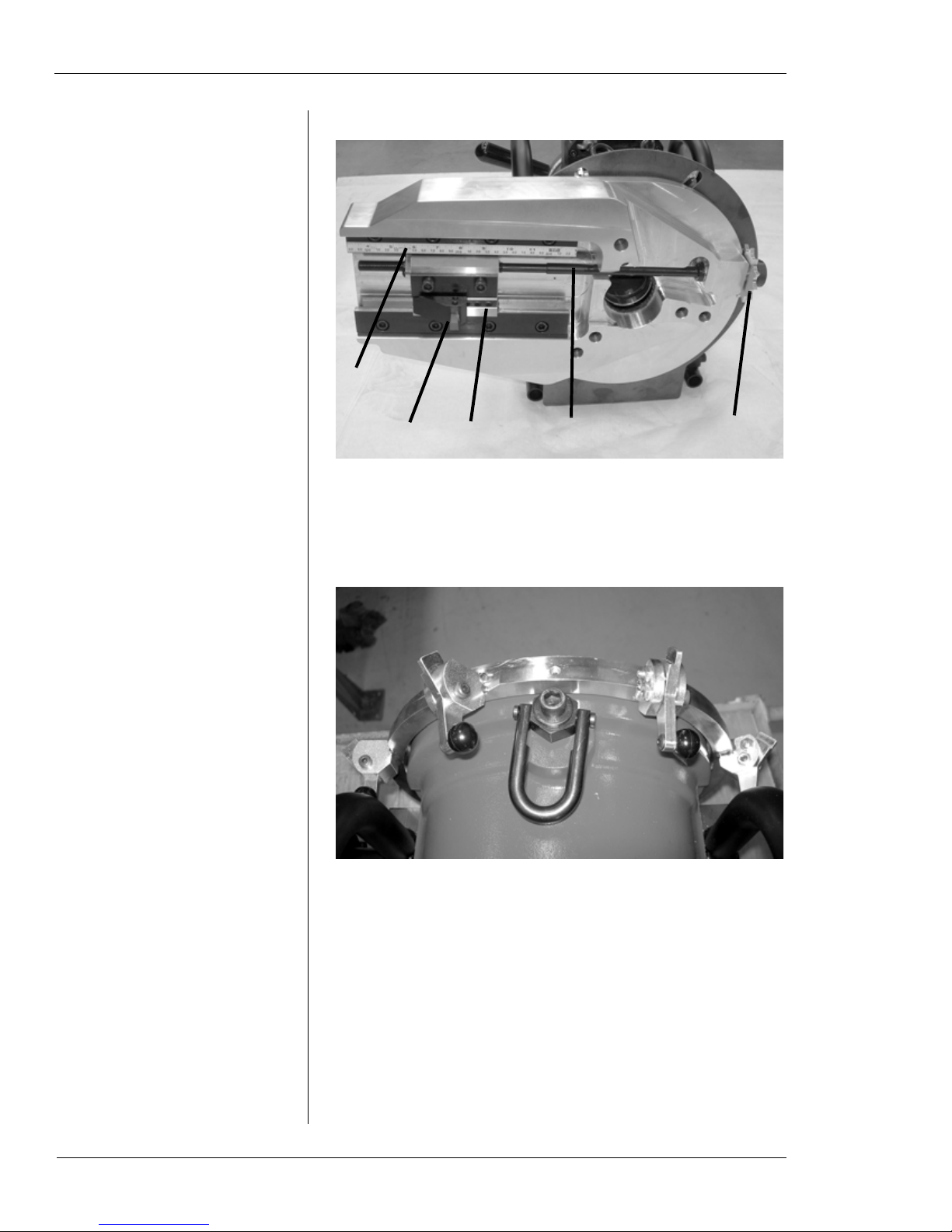
• radial feed trip assembly
Figure 3-4. The photo shows the trip assembly
mounted on the main drive housing.
14 Part No. 81-MAN-00, Rev. 0-0610 E.H. Wachs
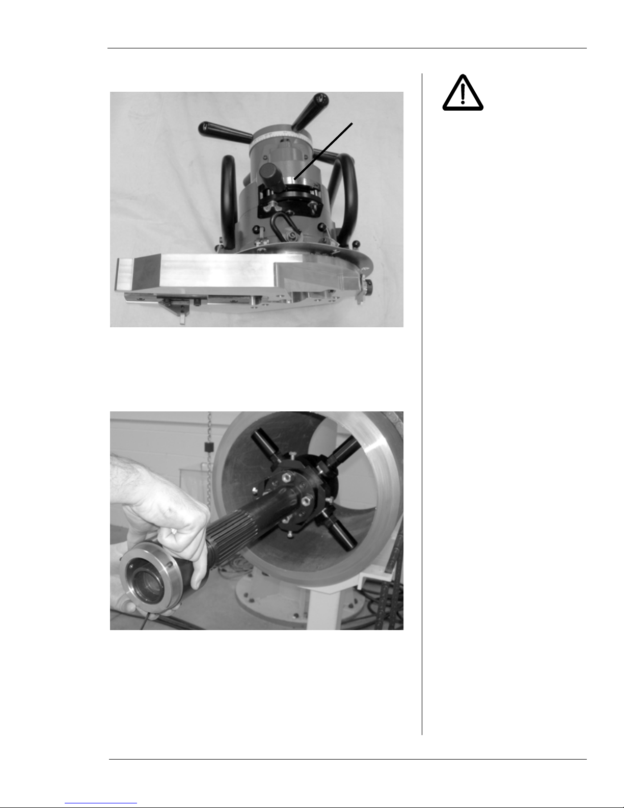
• Speed Prep autofeed module
WARNING
Speed Prep
module
Chapter 3, Introduction to the Equipment: Overview of the EP 424
The Speed Prep autofeed
can feed the machine until it
comes off the mandrel.
Crushing or other serious
injuries could occur. Use the
autofeed stop plate (81-316-
00) to keep the machine from
feeding too far.
Figure 3-5. The speed prep module is installed on the
main drive to operate the feed mechanism for singlepoint beveling.
• independent chuck mandrel
Figure 3-6. The independent chuck mandrel allows
you to center the machine on the O.D. of the pipe.
E.H. Wachs Part No. 81-MAN-00, Rev. 0-0610 15
EP 424 End Prep Machine
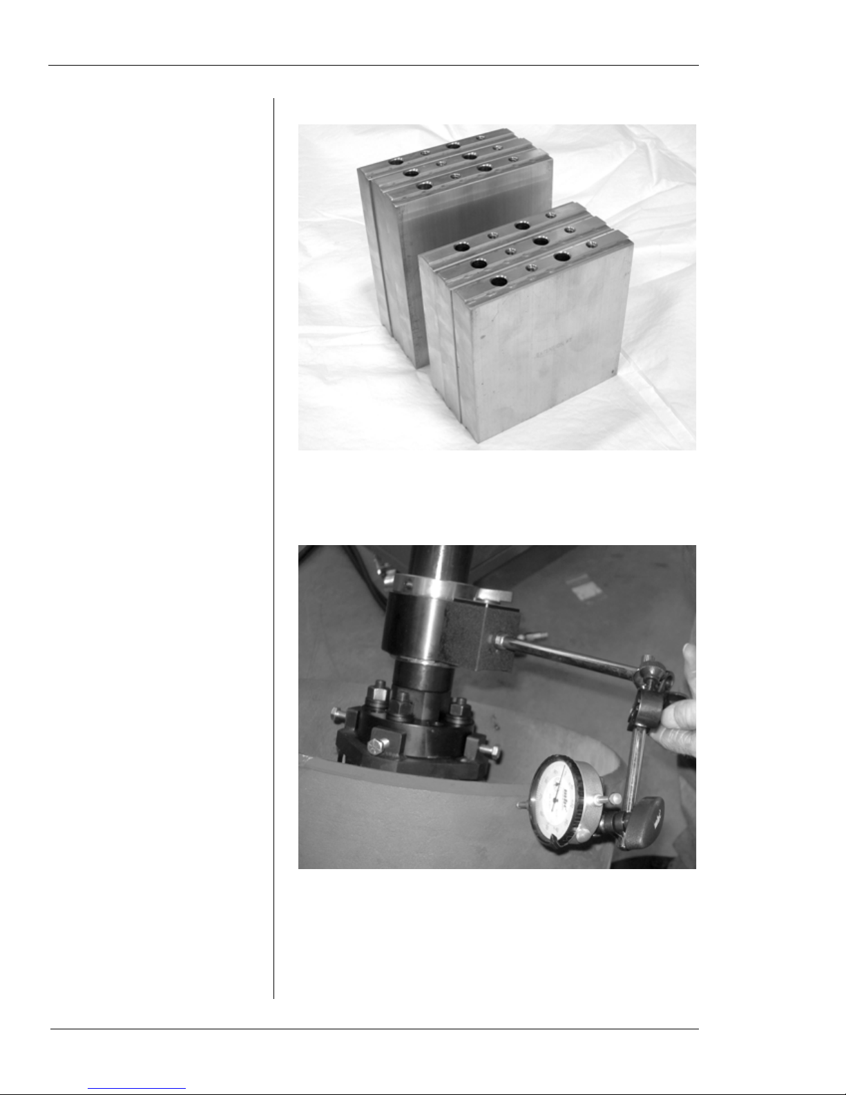
• extension leg kit for standard mandrel
Figure 3-7. Two sets of extension legs allow the standard mandrel to be mounted in pipes up to 23.64” I.D.
• dial indicator assembly
16 Part No. 81-MAN-00, Rev. 0-0610 E.H. Wachs
Figure 3-8. The dial indicator is provided for centering the independent chuck in the pipe.
Chapter 3, Introduction to the Equipment: Overview of the EP 424
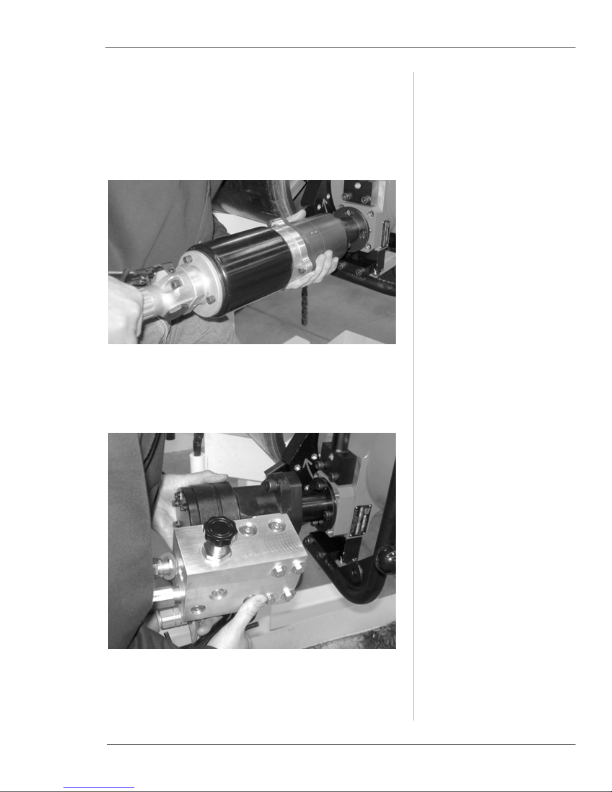
Drive Motors
Two drive motors are available for the EP 424:
• a 3.5 HP air motor, part no. 81-311-00. The air motor
requires 95 cfm air flow at 90 psi (2,700 l/min at 6.2
bar).
Figure 3-9. The photo shows the EP 424 air motor.
• a hydraulic motor, part no. 81-310-00. The hydraulic
motor requires 10 gpm flow at 1500 psi (38 l/min @103
bar).
Figure 3-10. The hydraulic motor is interchangeable
with the air motor.
E.H. Wachs Part No. 81-MAN-00, Rev. 0-0610 17

EP 424 End Prep Machine
Both motors include adapters for the EP 424. The motors
are interchangeable, requiring no modifications to the EP
424 machine.
Accessories
The following accessories are available for the EP 424:
• Single-point upgrade kit, part no. 81-400-00 (for formtool machine configuration); includes Speed Prep module, single-point slide, trip ring, and independent chuck.
• Extension leg kit for standard mandrel, part no. 81-303-
01. Extends maximum clamping I.D. to 23.64” (600.5
mm).
• Independent chuck mandrel, part no. 81-305-00. (Provided with single-point machine or kit; available as
option for form tool machine.)
• Short perch mandrel, part no. 81-315-00. Self-centering
mandrel for pipes with bends or limited I.D. access.
• Air treatment module, part no. 26-407-00.
18 Part No. 81-MAN-00, Rev. 0-0610 E.H. Wachs

SPECIFICATIONS
Capacities
Table 1: EP 424 Operating Capacities
Chapter 3, Introduction to the Equipment: Specifications
Air requirements
Hydraulic requirements
Axial feed 0.071” per feed handle revolution
Single-point slide radial feed
Max feed travel 3.50” (88.9 mm)
Max. rotating speed (no
load)
Min. pipe wall thickness Schedule 40
Max. pipe wall thickness
(form tool)
Max pipe wall thickness (sin-
gle-point)
Lift hook capacity 1000 lb (454 kg)
95 cfm at 90 psi
(2690 l/min at 6.2 bar)
Min 10 gpm/max 15 gpm at 2000 psi
(38/57 l/min at 138 bar)
0.0052” (0.132 mm) per engaged trip;
6.5” (165 mm) maximum feed
20 rpm
1.6” (40.5 mm), depending on material
6.5” (165 mm)
Dimensions and Weights
The envelope drawings in the following section include the
dimensions for each machine configuration, and the weight
for each subassembly. Table 2 below includes overall
dimensions and weights for each configuration.
Table 2: Overall Dimensions and Weights
Configuration
81-000-01
(Form tool/air
drive)
81-000-02
(Form tool/
hydraulic drive)
Dimensions
(L x W x H)
28.8” x 36.2” x 16.1”
(732 x 919 x 408 mm)
28.8” x 25.3” x 16.1”
(732 x 643 x 408 mm)
154.5 lb (70.2 kg)/
172 lb (78.2 kg)
162 lb (73.6 kg)/
179.5 lb/81.6 kg
E.H. Wachs Part No. 81-MAN-00, Rev. 0-0610 19
Weight
(Std. Mandrel/
Ind. Chuck Mandrel)

EP 424 End Prep Machine
Table 2: Overall Dimensions and Weights
Weight
(Std. Mandrel/
Ind. Chuck Mandrel)
Configuration
81-000-03
(Single-point/air
drive)
81-000-04
(Single-point/
hydraulic drive)
Shipping/
storage case
Dimensions
(L x W x H)
25.5” x 42.3” x 21.2”
(648 x 1075 x 539 mm)
25.4” x 30.4” x 21.2”
(645 x 772 x 539 mm)
37” x 36.3” x 22.3”
(940 x 922 x 566 mm)
176 lb (80 kg)/
193.5 lb (88 kg)
183.5 lb (83.4 kg)/
201 lb (91.4 kg)
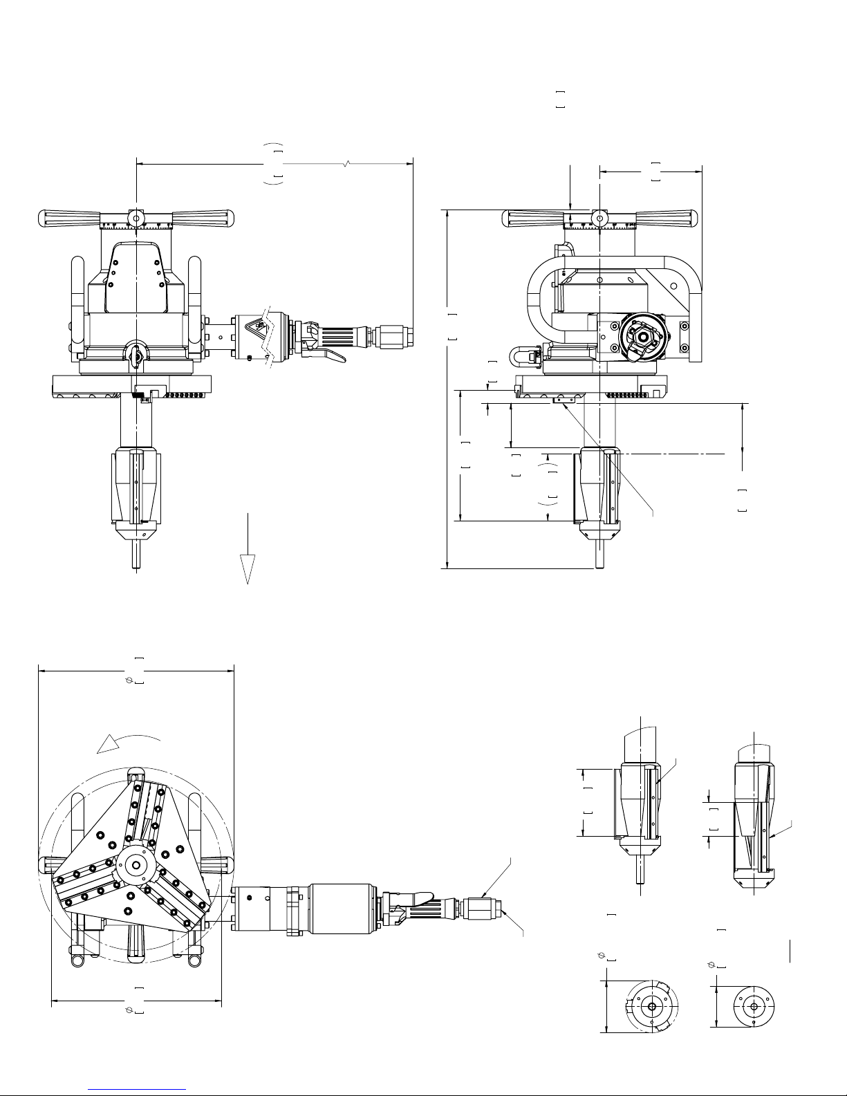
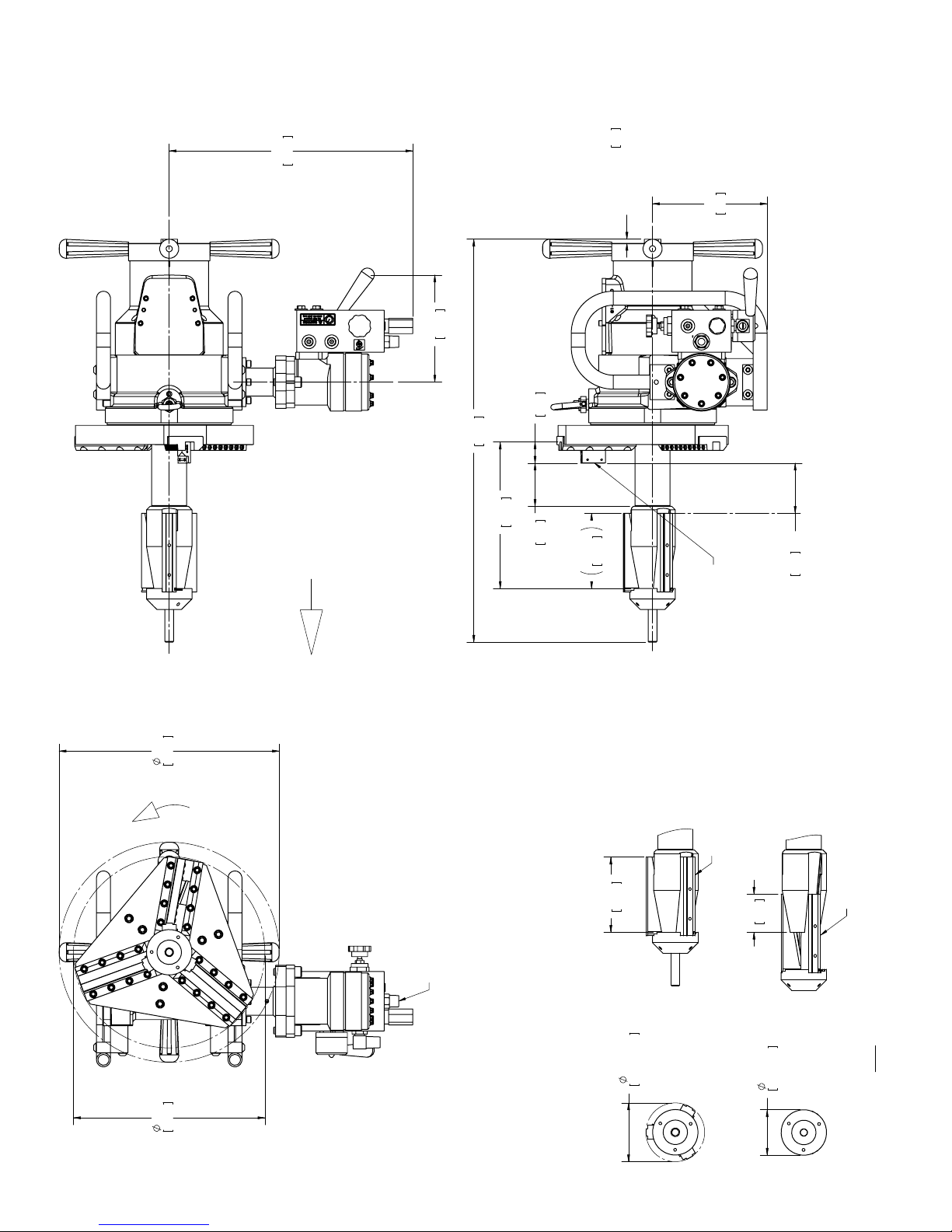
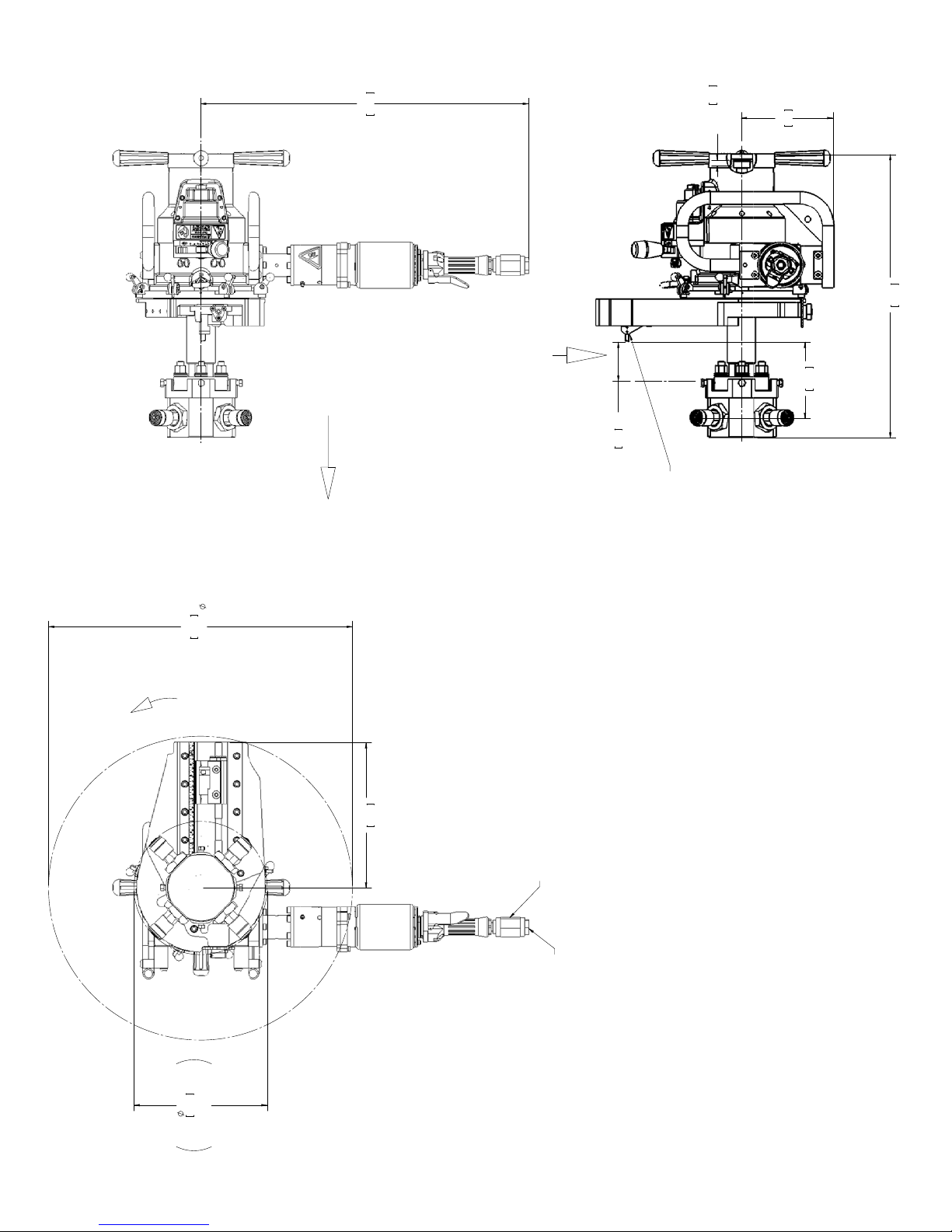
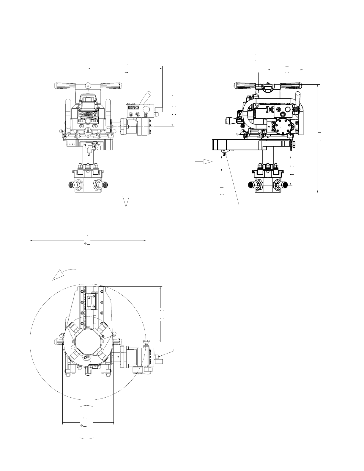
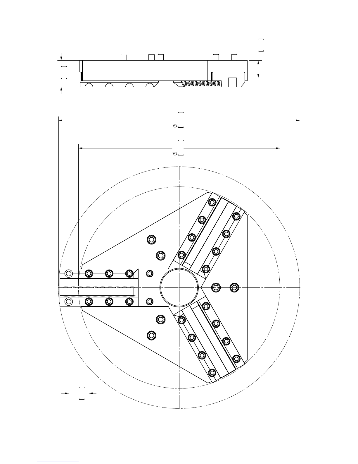
OPERATING ENVELOPE
The drawings on the following pages illustrate the operating
envelope for all configurations of the EP 424:
• Standard machine with air drive (81-000-01)
• Standard machine with hydraulic drive (81-000-02)
• Single-point machine with air drive (81-000-03)
• Single-point machine with hydraulic drive (81-000-04).
There are also dimensional drawings for the following components:
• Standard mandrel with extension legs
• Form tool rotating head
• Independent chuck mandrel with extension legs
• Single-point slide.
20 Part No. 81-MAN-00, Rev. 0-0610 E.H. Wachs
29.31
744.6
AXIAL FEED: .071"[1.80] PER FEED
HANDLE REVOLUTION
(CLOCKWISE)
28.81
731.6
10.47
265.9
1.02
25.9
3.59
91.1
7.5
.29
(SHOWN WITH
ON MANDREL)
.50 [12.7] TREAD ENGAGEMENT
5.38
136.5
208
8.19
&
56-198-02
56-711-01
INSERT HOLDER
3.50
88.9
TOOL
FACING/BEVELING
Operating Envelope
EP 424 Air Drive Conguration
81-000-01
MAX TRAVEL
15.73
13.68
399.5
347.5
20 RPM
MAX FREE SPEED
5.38
136.5
AIR REQUIREMENTS
AIR CONSUMPTION 95 cfm [2690 l/min]
PRESSURE 90 PSI [6.2 BAR]
MAX
MAX
4.20
1/2 NPT
106.6
LEGS SHOWN FULLY EXTENDED
2.72
69.2
MIN
MIN
3.25
82.6
LEGS SHOWN FULLY RETRACTED
NOTE:
SEE 81-303-00 FOR ALL
EXTENSION RANGES
17.41
442.3
.29
7.5
(SHOWN WITH
ON MANDREL)
7.66
AXIAL FEED: .071"[1.80] PER FEED
HANDLE REVOLUTION
(CLOCKWISE)
194.5
28.81
731.6
10.47
265.9
1.52
3.09
38.6
78.4
5.38
.50"[12.7] THREAD ENGAGEMENT
136.5
208
8.19
&
56-711-01
56-198-02
INSERT HOLDER
FACING/BEVELING
TOOL
3.50
88.9
Operating Envelope
MAX TRAVEL
EP 424 Hydraulic Drive Conguration
81-000-02
15.73
13.68
399.5
347.5
20 RPM
MAX FREE SPEED
MAX FLOW 15 GPM [57 LPM]
MAX PRESSURE 2000 PSI [138 BAR]
5.38
136.5
MAX
4.20
MAX
106.7
LEGS SHOWN FULLY EXTENDED
2.72
69.2
MIN
MIN
3.25
82.6
LEGS SHOWN FULLY RETRACTED
NOTE:
SEE 81-303-00 FOR ALL
EXTENSION RANGES
29.31
744.6
.50
12.7
ON MANDREL
THREAD ENGAMENT
8.19
208
25.35
643.8
27.15
689.7
ROTATING
20 RPM
MAX FREE SPEED
AXIAL FEED: .071" [1.80] PER FEED
HANDLE REVOLUTION
(CLOCKWISE)
13.00
330.2
FEED RATE: .0052" [.132]
PER TRIP ENGAGED
TOTAL STROKE: 6.5" [165.1]
3.50
88.9
MAX TRAVEL
&
HOLDER
56-205-01
52-701-01
INSERT TOOL
6.84
173.6
Operating Envelope
EP 424 Air Drive Conguration
Single-Point Operation
81-000-03
11.90
302.3
(SEE 81-305-00
FOR FULL LEG CHART)
AIR REQUIREMENTS
AIR CONSUMPTION 95 cfm [2690 l/min]
PRESSURE 90 PSI (6.2 bar)
1/2 NPT
17.41
442.3
AXIAL FEED: .071" [1.80] PER FEED
HANDLE REVOLUTION
(CLOCKWISE)
7.66
194.5
FEED RATE: .0052" [.132]
PER TRIP ENGAGED
TOTAL STROKE: 6.5" [165.1]
3.50
88.9
MAX TRAVEL
&
HOLDER
56-205-01
.50
12.7
52-701-01
INSERT TOOL
ON MANDREL
THREAD ENGAMENT
8.19
208
25.35
643.8
6.84
173.6
27.15
689.7
20 RPM
MAX FREE SPEED
13.00
330.2
MAX FLOW 15 GPM [57 LPM]
MAX PRESSURE 2000 PSI [138 BAR]
Operating Envelope
EP 424 Hydraulic Drive Conguration
Single-Point Operation
81-000-04
11.94
303.2
SEE 81-305-00
FOR FULL LEG CHART
MIN
3.27
MIN
83.1
MIN I.D. WITH
3.15
80.1
.50
12.7
Operating Envelope
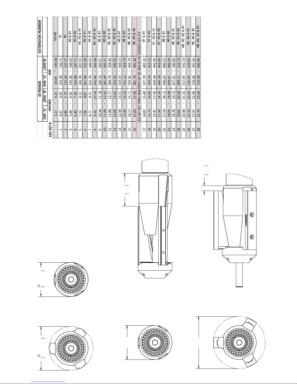
EP 424 Standard Mandrel and Extension Legs
81-303-00
MAX
MAX
4.20
MAX I.D. WITH
"A"
MIN
MIN POSITION
"B"
MAX POSITION
MAX
1.79
45.3
16.39
416.2
13.68
347.4
1.19
30.1
Operating Envelope
EP 424 Rotating Tool Head
81-304-00
TOOL HOLDER
SHOWN IN OUTER POSITION
1.38
34.9

MM
ID RANGE
INCHES
8.50 - 10.50 215.9 - 266.7
9.50 - 11.50 241.3 - 292.1
11.18 - 13.15 284.0 - 334.0
INDEPENDENT CHUCK MANDREL
12.18 - 14.15 309.4 - 359.4
14.43 - 16.50 366.5 - 419.1
15.43 - 17.50 391.9 - 444.5
16.87 - 18.81 428.5 - 477.8
17.87 - 19.81 453.9 - 503.2
19.31 - 21.30 490.5 - 541.0
20.31 - 22.30 515.9 - 566.4
22.28 - 24.28 565.9 - 616.7
23.28 - 25.28 591.3 - 642.1
1.75
44.5
24.85
631.1
LEG SET
23-313-00
23-214-01
(23-221-00)
WITH SPACER
23-214-02
(23-221-00)
WITH SPACER
(23-221-00)
WITH SPACER
25.28
23-214-03
642.1
23-214-04
(23-221-00)
WITH SPACER
MAX CLAMPING
23-214-05
(23-221-00)
WITH SPACER
(23-221-00)
WITH SPACER
Operating Envelope
EP 424 Independent Chuck Mandrel
and Extension Legs
81-305-00
8.50
215.9
MIN CLAMPING

26.38
670
MAX TOOL POSTION
TOOL HOLDER 56-205-01
& INSERT TOOL 52-701-01
SHOWN WITH HIGH RANGE
13.58
R
344.8
7.25
184.1
2.55
64.7
Operating Envelope
EP 424 Single-Point Slide
81-306-00
23.62
599.8
MAX TOOL POSTION
TOOL HOLDER 56-205-00
& INSERT TOOL 52-701-01
SHOWN WITH LOW RANGE
SHOWN WITH .50"
THREAD ENGAGMENT
& 3 TOOL HOLDER SCREWS
SLIDE TRAVEL: 6.5"
4.25
107.9
MIN TOOL POSTION
TOOL HOLDER 56-205-01
& INSERT TOOL 52-701-01
SHOWN WITH HIGH RANGE
MIN TOOL POSTION
TOOL HOLDER 56-205-00
& INSERT TOOL 52-701-01
SHOWN WITH LOW RANGE

Chapter 4
Assembly,
Disassembly, and
Storage
Chapter 4, Assembly, Disassembly, and Storage
In This Chapter
PACKAGING
The EP 424 comes in a customized steel shipping/storage
case. The case includes compartments for all standard and
optional components, and is designed to hold all components securely to prevent damage in shipping.
Store the machine in its case at all times when it is not in
use. Figure 4-1 shows the layout of the components in the
case. There are lockdown pins for securing the EP 424
machine, as shown in Figure 4-2.
PACKAGING
STORAGE CHECKLIST
Figure 4-1. The photo shows the EP 424 in its case.
E.H. Wachs Part No. 81-MAN-00, Rev. 0-0610 29

EP 424 End Prep Machine
Figure 4-2. Two lockdown pins are provided to secure
the machine in the storage case. Always insert the pins
through the case brackets and the EP 424 handle
when storing the machine.
STORAGE CHECKLIST
Before storing the EP 424, perform the following maintenance steps. If you are using the machine in an especially
dirty or corrosive environment, perform these steps frequently.
• Clean the machine by wiping off dirt, debris, and accumulated oil or grease.
• Put oil in the air motor oiler, and operate the motor for a
few seconds to lubricate its internal components.
• Lubricate the machine according to the instructions in
Chapter 6.
• Spray or wipe a light coating of anti-corrosion lubricant
on non-finished, non-painted surfaces.
• Put the machine in its storage case, with all components
stored in their compartments.
• If possible, keep the storage case indoors and away from
moisture.
• If you will be storing the machine longer than 30 days,
put desiccant packets in the case to prevent corrosion.
30 Part No. 81-MAN-00, Rev. 0-0610 E.H. Wachs

Chapter 5
Operating
Instructions
MOUNTING THE MANDREL ON THE PIPE
Typically, you will install the mandrel (either the standard
or independent chuck mandrel) in the pipe before mounting
the EP 424 machine. This makes it easier to align the mandrel and mount the machine.
Chapter 5, Operating Instructions
In This Chapter
MOUNTING THE MANDREL ON
THE PIPE
USING THE DRIVE MOTORS
FORM TOOL OPERATION
SINGLE POINT OPERATION
The standard mandrel is recommended when it can be used
on the pipe. It is self-centering, and is quicker and easier to
mount than the independent chuck mandrel. The standard
mandrel can be mounted in pipes with an I.D. range from
3.27” to 23.64” (83.1 to 600.5 mm).
The workpiece may not be suitable for the standard mandrel, such as in the following situations:
• the I.D. of the pipe is uneven or eroded
• the end of the pipe is on a bend
• the end surface of the pipe is not square
• you need to center the operation on the O.D. of the pipe.
In these cases, you will need to use the independent chuck
mandrel. You can use the independent chuck mandrel for
either form tool or single-point operation. The independent
chuck mandrel can be mounted in pipes with an I.D. range
from 8.50” to 25.28” (215.9 to 642.1 mm).
E.H. Wachs Part No. 81-MAN-00, Rev. 0-0610 31

EP 424 End Prep Machine
NOTE
NOTE
If the pipe I.D. is larger than
15.96” (405.4 mm), you will
need the extended leg kit.
Mounting the Universal (Standard) Mandrel
Measure the I.D. of the pipe.
1.
See the envelope drawings in
Chapter 3 for an illustration of
the clamp leg configurations.
Figure 5-1. Measure the I.D. of the pipe to determine
which leg set will be required.
Refer to the clamp leg chart in Table 1 to select the
2.
correct combination of clamp legs. Find the I.D. you
measured (inches or mm) in the appropriate column
on the left, then select the leg extensions listed in the
column on the right.
32 Part No. 81-MAN-00, Rev. 0-0610 E.H. Wachs

Chapter 5, Operating Instructions: Mounting the Mandrel on the Pipe
Table 1: Standard Mandrel Clamping Leg Chart
I.D. Inches I.D. mm
Min Max Min Max
3.27 4.20 83.1 106.7 None
4.07 4.99 103.4 126.8 #1
4.86 5.79 123.4 147.1 #2
5.64 6.56 143.3 166.6 #3 & #1
6.46 7.39 164.1 187.7 #3 & #2
7.22 8.15 183.4 207.1 #3, #2, & #1
7.94 8.87 201.7 225.3 #4 & #1
8.77 9.71 222.8 246.6 #4 & #2
9.53 10.46 242.1 265.7 #4, #3, & #1
10.24 11.18 260.1 284.0 #5 & #1
11.09 12.02 281.7 305.3 #5 & #2
11.84 12.77 300.7 324.4 #5, #3, & #1
12.69 13.62 322.3 346.0 #5, #3, & #2
12.58 1 3.51 319.5 343.2 #6 & #1
13.43 1 4.36 341.1 364.7 #6 & #2
14.17 15.11 359.9 383.8 #6, #3, & #1
15.03 15.96 381.8 405.4 #6, #3, & #2
Leg Extensions Used
With 81-303-01 Extended Leg Kit
14.87 1 5.80 377.7 401.3 #7 & #1
15.73 1 6.66 399.5 423.2 #7 & #2
16.47 17.40 418.3 442.0 #7, #3, & #1
17.33 18.26 440.2 463.8 #7, #3, & #2
17.19 1 8.12 436.6 460.3 #8 & #1
18.05 1 8.98 458.5 482.1 #8 & #2
18.78 19.72 477.0 500.9 #8, #3, & #1
19.65 20.58 499.1 522.7 #8, #3, & #2
20.38 2 1.32 517.7 541.5 #8, #3, #2, & #1
21.10 22.04 535.9 559.8 #8, #4, & #1
21.97 22.90 558.0 581.7 #8, #4, & #2
22.70 2 3.64 576.6 600.5 #8, #4, #3, & #1
Using a 3/16” hex wrench, attach the clamping legs to
3.
the mandrel chuck legs with the captivated screws. If
you are using more than one leg set, install the largest
E.H. Wachs Part No. 81-MAN-00, Rev. 0-0610 33

EP 424 End Prep Machine
NOTE
Extension leg #1 does not
have threaded holes to install
other legs on top of it.
leg first, then “stack” them in size order. Make sure
the legs seat squarely, then securely tighten the
screws.
Figure 5-2. Screw the captivated scr ews into the mandrel to secure the legs.
Always install extension leg #1 or #2 last, on top of
4.
the others. These legs are steel for greater durability.
34 Part No. 81-MAN-00, Rev. 0-0610 E.H. Wachs
Figure 5-3. Use the steel extension legs (#1 or #2) on
top when installing multiple legs.

Chapter 5, Operating Instructions: Mounting the Mandrel on the Pipe
NOTE
NOTE
Using a 1-1/16” wrench or socket, turn the drawbar
5.
nut counter-clockwise to retract the clamping legs.
Figure 5-4. Turn the drawbar nut counter-clockwise
to retract the clamping legs.
Insert the clamping legs into the I.D. of the pipe. Hold
6.
the mandrel so that the legs are far enough inside the
end of the pipe to be out of the way of the machining
operation.
A socket wrench and 1-1/16”
socket are provided with the
EP 424.
For stability, the clamp legs
should be as close as possible to the end of the pipe.
However, make sure they are
far enough into the pipe to
avoid being damaged during
the operation. This is espe-
cially critical if you are
counterboring.
Figure 5-5. Insert the clamping legs into the pipe.
Turn the drawbar nut clockwise to clamp the legs
7.
inside the pipe until they are snug enough to hold the
mandrel.
E.H. Wachs Part No. 81-MAN-00, Rev. 0-0610 35

EP 424 End Prep Machine
Figure 5-6. Turn the drawbar nut clockwise until the
clamping legs are snug in the I.D. of the pipe.
Check that the legs are square on the pipe I.D., and are
8.
far enough from the pipe end for the operation.
Figure 5-7. Measur e the distance from the pipe end to
the clamping legs to make sure there is enough clearance for the operation.
If necessary, adjust the position of the clamping legs.
9.
Then turn the drawbar nut clockwise to clamp the legs
securely in the pipe.
36 Part No. 81-MAN-00, Rev. 0-0610 E.H. Wachs

Chapter 5, Operating Instructions: Mounting the Mandrel on the Pipe
NOTE
Mounting the Independent Chuck Mandrel
Start with the chuck body separated from the mandrel.
Measure the I.D. of the pipe.
1.
Figure 5-8. Measure the I.D. of the pipe to determine
which leg set will be required.
Refer to the clamp leg chart in Table 2 to select the
2.
correct clamp legs. Find the I.D. you measured (inches
or mm) in the appropriate column on the left, then
select the leg set listed in the column on the right.
See the envelope drawings in
Chapter 3 for an illustration of
the clamp leg configurations.
E.H. Wachs Part No. 81-MAN-00, Rev. 0-0610 37

EP 424 End Prep Machine
Table 2: Independent Chuck Clamping Leg Chart
I.D. Inches I.D. mm
MinMaxMinMax
8.50 10.50 215.9 266.7 23-313-00 No
9.50 11.50 241.3 292.1 23-313-00 Yes
1 1.18 13.15 284.0 334.0 23-214-01 No
12.18 14.15 309.4 359.4 23-214-01 Yes
14.43 16.50 366.5 419.1 23-214-02 No
15.43 17.50 391.9 444.5 23-214-02 Yes
16.87 18.81 428.5 477.8 23-214-03 No
17.87 19.81 453.9 503.2 23-214-03 Yes
19.31 21.30 490.5 541.0 23-214-04 No
20.31 22.30 515.9 566.4 23-214-04 Yes
22.28 24.28 565.9 616.7 23-214-05 No
23.28 25.28 591.3 642.1 23-214-05 Yes
Screw the 4 chuck legs into the chuck body. Leave
3.
Leg Set Used
Spacer (23-221-
00) Used
about 1/2” of threads exposed for the jam nut.
38 Part No. 81-MAN-00, Rev. 0-0610 E.H. Wachs
Figure 5-9. Screw the chuck legs into the chuck.
Put a jam nut over each leg, with the “shoulder” side
4.
of it toward the chuck body . Thread it a few turns onto
the chuck leg.

Chapter 5, Operating Instructions: Mounting the Mandrel on the Pipe
Shoulder
Figure 5-10. Put on the jam nut as shown, with the
shoulder of the nut toward the chuck.
If chuck leg spacers (23-221-00) are required, install a
5.
spacer over each of the 4 independent chuck buttons.
Figure 5-11. If required, put a chuck leg spacer on
each chuck button end.
Insert a button into the end of each chuck leg. The but-
6.
tons are fitted with o-rings to hold them in the leg.
E.H. Wachs Part No. 81-MAN-00, Rev. 0-0610 39

EP 424 End Prep Machine
Figure 5-12. Put buttons on the end of each chuck leg.
Place the chuck body inside the I.D. of the pipe and
7.
screw the legs out to snug them against the I.D.
40 Part No. 81-MAN-00, Rev. 0-0610 E.H. Wachs
Figure 5-13. Screw the legs out to snug the chuck
inside the pipe.
Remove the nuts from the 4 threaded studs, and put
8.
the interlocking pieces of the alignment gauge over
the studs with the scale sides facing you.

Chapter 5, Operating Instructions: Mounting the Mandrel on the Pipe
Figure 5-14. Mount the alignment gauge to the studs
in the chuck.
Screw the nuts onto the studs to secure the alignment
9.
gauge. The gauge pieces should be tight against the
face plate. You may have to move the chuck out to
tighten the gauge against the face plate.
Figure 5-15. The alignment gauge must be flush
against the face plate surface.
Loosen the clamp legs slightly, and push the chuck
10.
body into the pipe until all four ends of the alignment
E.H. Wachs Part No. 81-MAN-00, Rev. 0-0610 41

EP 424 End Prep Machine
NOTE
gauge are touching the end of the pipe. Re-tighten the
legs to hold the chuck body in place.
You will roughly center the
chuck body in the pipe (to the
precision of the alignment
gauge scales). You will precisely center the mandrel
later in this procedure.
Figure 5-16. Push the chuck body into the pipe until
all four arms of the alignment gauge are against the
pipe surface.
To center the chuck body, refer to the scales on the
11.
alignment gauges. Using a 1-1/8” end wrench on the
flats of the chuck legs, turn opposite legs in or out
until the scale touches the pipe I.D. at the same distance on both sides.
Figure 5-17. Alternately adjust opposite legs to center
the chuck in the pipe.
42 Part No. 81-MAN-00, Rev. 0-0610 E.H. Wachs
When the chuck body is centered, use a 2-1/4” wrench
12.
to snug the jam nuts against the chuck body.

Chapter 5, Operating Instructions: Mounting the Mandrel on the Pipe
Figure 5-18. When the chuck is rough centered, snug
the jam nuts to hold the clamping legs in place.
Remove the alignment gauge from the studs. Make
13.
sure you have the nut and both washers removed from
each stud.
Figure 5-19. Remove the alignment gauge and the
nuts and washers from the chuck studs.
E.H. Wachs Part No. 81-MAN-00, Rev. 0-0610 43

EP 424 End Prep Machine
NOTE
If the chuck does not need
any further centering adjustment, install a spacer (23203-00) over each stud
before mounting the mandrel.
Mount the mandrel onto the chuck.
14.
Figure 5-20. Mount the mandrel on the independent
chuck.
Replace the 2 washers (female washer first) and the
15.
nut onto each stud to hold the mandrel in place. Snug
the nuts to finger tightness.
Place the indicator mounting collar over the mandrel
16.
and slide it close to the pipe.
44 Part No. 81-MAN-00, Rev. 0-0610 E.H. Wachs
Figure 5-21. Slide the indicator collar over the end of
the mandrel.

Chapter 5, Operating Instructions: Mounting the Mandrel on the Pipe
Tighten the set screws in the indicator collar to hold it
17.
in place on the mandrel.
Figure 5-22. Position the collar near the pipe surface
and tighten the set screws to hold it in place.
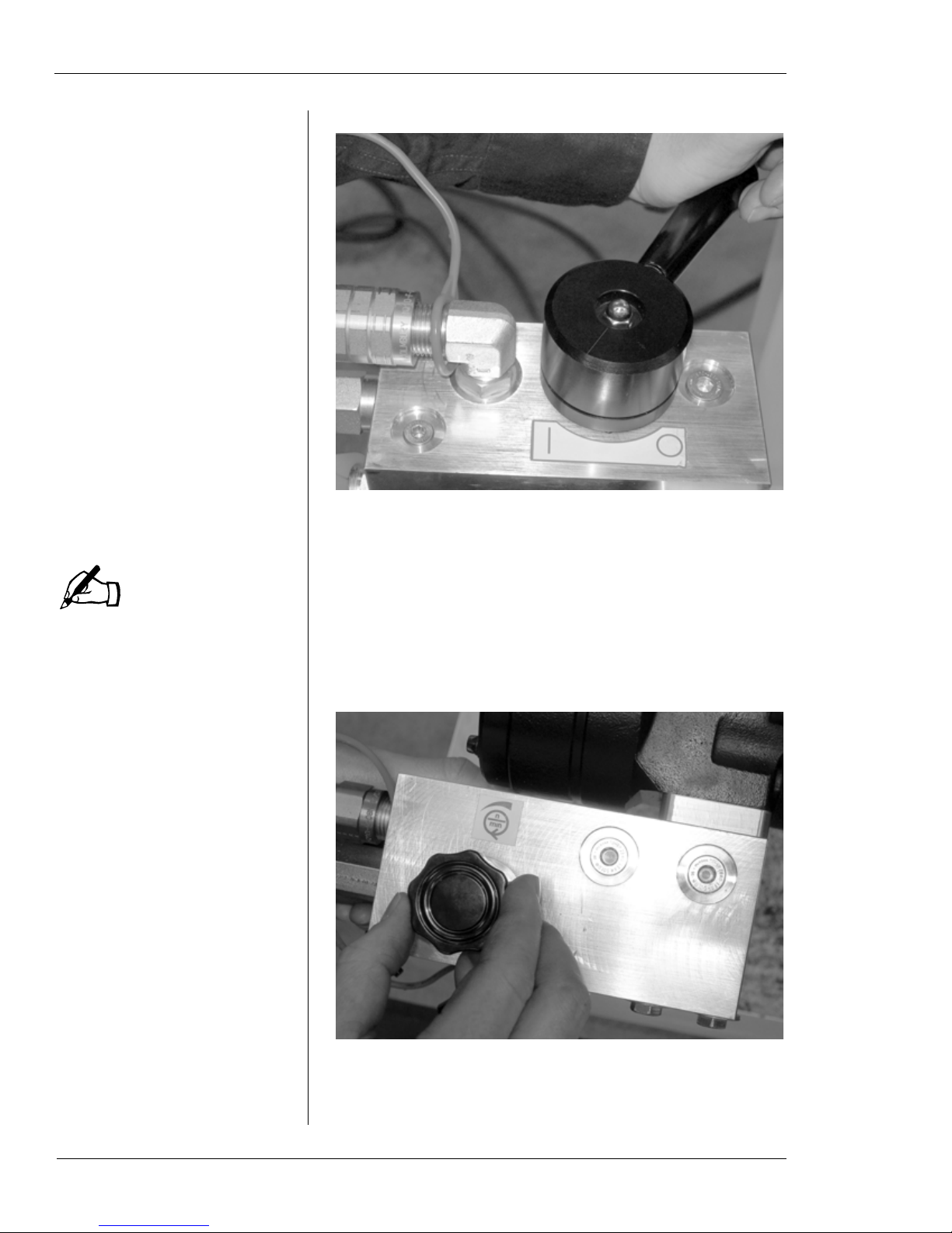
Assemble the indicator and set the magnetic mount
18.
onto the indicator mounting collar. T urn the magnet on
to hold the indicator in place.
Figure 5-23. Set the magnetic base of the indicator on
the collar, and turn the switch on to engage the magnet.
Position the tip of the indicator to touch the pipe sur-
19.
face. You can indicate on either the O.D. or the I.D. of
the pipe, depending on where the operation needs to
be centered.
E.H. Wachs Part No. 81-MAN-00, Rev. 0-0610 45

EP 424 End Prep Machine
NOTE
Do not adjust the mandrel
centering screws if stud spacers (23-203-00) are installed.
The mandrel position cannot
be adjusted with the spacers.
Figure 5-24. Set the tip of the indicator to touch the
pipe, perpendicular to the surface.
Move the indicator around the pipe end by rotating the
20.
mounting collar. Check the reading on the indicator
dial to measure how far the mandrel is off center.
46 Part No. 81-MAN-00, Rev. 0-0610 E.H. Wachs
Figure 5-25. Sweep the indicator around the pipe surface to check centering of the mandrel. You can center
on either the O.D. or the I.D. of the pipe, as required
for the operation.

To center the mandrel, adjust the mandrel centering
21.
screws in the face plate.
Chapter 5, Operating Instructions: Using the Drive Motors
Figure 5-26. Turn the mandrel centering screws to
adjust the position of the mandrel.
When you have the mandrel centered, tighten down
22.
the nuts on the mandrel mounting studs.
Remove the indicator and the indicator mounting col-
23.
lar.
USING THE DRIVE MOTORS
Refer to the instructions in this section for the drive motor
(air or hydraulic) provided with your EP 424 machine. The
motors are installed and operated the same way for either
form tool or single-point operation.
Mounting and Operating the Air Drive
T o install the air motor , put the motor flange over the 4
1.
motor mounting screws on the EP 424 motor adapter.
You may have to rotate the motor slightly to engage
the spline in the shaft.
E.H. Wachs Part No. 81-MAN-00, Rev. 0-0610 47

EP 424 End Prep Machine
NOTE
Figure 5-27. Put the air motor flange over the screws
in the motor adapter.
Rotate the air motor to secure the screw heads in the
2.
slotted holes of the flange. Using a 1/4” hex wrench,
tighten the screws securely.
The air supply must provide
95 cfm at 90 psi (2700 l/min
at 6.2 bar).
48 Part No. 81-MAN-00, Rev. 0-0610 E.H. Wachs
Figure 5-28. Turn the flange to seat the screws in the
slots, then tighten the screws.
Make sure the air supply is turned off at the source.
3.
Connect the air line to the connector on the air motor.
Turn on the air supply at the source.
4.
To operate the EP 424, squeeze the trigger on the air
5.
motor. The machine (form tool head or single-point
slide) will start to rotate.

Figure 5-29. Squeeze the air motor trigger to start the
NOTE
machine.
Adjust the motor speed by turning the speed control-
6.
ler.
Chapter 5, Operating Instructions: Using the Drive Motors
Figure 5-30. Turn the speed control collar to adjust
the rotation speed of the machine.
While holding the air motor trigger, operate the
7.
machine as described in the appropriate section below
(form tool or single-point operation).
As the machine cuts, adjust the air motor speed if nec-
8.
essary to reduce chatter and achieve the appropriate
end prep finish.
When the prep is complete, release the air motor trig-
9.
ger to stop the machine.
E.H. Wachs Part No. 81-MAN-00, Rev. 0-0610 49
The use of coolant or cutting
lubricant is recommended.
This will improve the cutting
performance and increase
the life of the tooling.

EP 424 End Prep Machine
Mounting and Operating the Hydraulic Drive
To install the hydraulic motor, put the motor flange
1.
over the 4 motor mounting screws on the EP 424
motor adapter. You may have to rotate the motor
slightly to engage the spline in the shaft.
Figure 5-31. Mount the hydraulic motor flange onto
the screws in the motor adapter.
Turn the flange to engage the screw heads in the slots,
2.
then tighten the screws using a 1/4” hex wrench.
50 Part No. 81-MAN-00, Rev. 0-0610 E.H. Wachs
Figure 5-32. Turn the flange to seat the screws in the
slots, then tighten the screws.

Connect the hydraulic hoses to the ports on the motor
Tank (return)
connector
Pressure
connector
3.
as described in Figure 5-33.
Chapter 5, Operating Instructions: Using the Drive Motors
Figure 5-33. Connect the hydraulic hoses to the
motor as shown.
Turn on the hydraulic power supply. Set it to 10 gpm
4.
at 1500 psi (38 l/min at 103 bar).
Push the hydraulic drive lever toward the main body
5.
of the machine. The machine will start to rotate.
E.H. Wachs Part No. 81-MAN-00, Rev. 0-0610 51
EP 424 End Prep Machine
NOTE
The form tool head has
arrows indicating the correct
direction of rotation.
Figure 5-34. Turn the hydraulic lever to the ON position as shown.
Make sure the machine is turning clockwise. If it is
6.
turning the wrong way, the hydraulic hoses are
reversed. Turn off the HPU and switch the hoses.
Adjust the drive motor speed by turning the speed dial
7.
on the hydraulic motor.
52 Part No. 81-MAN-00, Rev. 0-0610 E.H. Wachs
Figure 5-35. Use the speed dial on the hydraulic manifold to adjust the machine rotation speed.

Chapter 5, Operating Instructions: Form Tool Operation
NOTE
NOTE
While holding the hydraulic drive lever on, operate
8.
the machine as described in the appropriate section
below (form tool or single-point operation).
As the machine cuts, adjust the hydraulic motor speed
9.
if necessary to reduce chatter and achieve the appropriate end prep finish.
When the prep is complete, release the hydraulic drive
10.
lever to stop the machine.
FORM TOOL OPERATION
The EP 424 has three tool holders, which can each hold a
different tool. This allows you to perform any combination
of facing, beveling, and counterboring simultaneously.
Make sure the EP 424 is set up as follows for form tool
operation:
The use of coolant or cutting
lubricant is recommended.
This will improve the cutting
performance and increase
the life of the tooling.
• Use the standard mandrel, if possible for the workpiece.
• Have the single-point slide removed and the rotating
tool head installed. (See “Removing the Single-Point
Kit” in the next section.)
• If your EP 424 is equipped with the Speed Prep autofeed
module, set the axial feed selector to 0° when doing
form tool operations.
Setting the feed selector to 0°
will reduce wear on the
Speed Prep components
when you are not using the
autofeed.
Figure 5-36. Set the Speed Prep selector to 0° before
doing form tool operations.
E.H. Wachs Part No. 81-MAN-00, Rev. 0-0610 53

EP 424 End Prep Machine
Planning the Operation
Operating Envelope
Make sure you have adequate clearance around the workpiece. See the operating envelope drawings in Chapter 3 for
reference.
Selecting Tooling
Use the following charts to select the appropriate tooling for
the operation.
54 Part No. 81-MAN-00, Rev. 0-0610 E.H. Wachs
Figure 5-37. The chart describes the tooling used for
facing/beveling operations.

Chapter 5, Operating Instructions: Form Tool Operation
Figure 5-38. The chart describes the tooling used for
counterboring.
Figure 5-39. The chart describes the tooling used for
deburring.
E.H. Wachs Part No. 81-MAN-00, Rev. 0-0610 55

EP 424 End Prep Machine
Figure 5-40. The chart describes the tooling used for
J-prep operations.
Adjusting the Tool Holder Positions
You may need to change the positions of the tool holders in
the rotating head, depending on the pipe diameter . Each tool
holder can be set to an “inner” (small diameter) or “outer”
(large diameter) position.
Using a 1/4” hex wrench, remove the 8 screws holding
1.
the tool holder to the rotating head. (Note: if the tool
holder is already in the outer position, it will have 6
screws holding it.)
56 Part No. 81-MAN-00, Rev. 0-0610 E.H. Wachs

Chapter 5, Operating Instructions: Form Tool Operation
Figure 5-41. The photo shows the tool holder moved
to the “outer” position for larger diameter pipes.
Move the tool holder to the other position. Line up the
2.
holes and re-insert the screws. Use 6 screws if setting
the holder to the outer position.
Setting Up and Mounting the EP 424
You will probably find it easiest to assemble the main components of the EP 424 as you install the machine. The following is the recommended sequence for installation:
• Configure and mount the mandrel in the workpiece, as
described at the beginning of this chapter.
• Install the machine body onto the mandrel.
• Install the tooling in the rotating tool head.
• Install the drive motor.
If desired, you can assemble the machine and then mount it
on the workpiece. You will need a lifting device to support
the machine as you mount it.
Assembling the Machine Components
The following procedure assumes that the mandrel has been
mounted in the pipe, as described earlier in this chapter.
E.H. Wachs Part No. 81-MAN-00, Rev. 0-0610 57

EP 424 End Prep Machine
NOTE
It is recommended that you
using a lifting device to pick
up the EP 424. If you are lifting it manually, have two
operators lift it.
Attach a crane or other lifting device to the lift hook
1.
on the machine body.
Figure 5-42. Attach the lifting device to the lift hook.
Use the lifting device to pick up the EP 424 and posi-
2.
tion it for mounting on the mandrel. If you do not have
a lifting device, two people can lift the machine into
place using the handles.
58 Part No. 81-MAN-00, Rev. 0-0610 E.H. Wachs
Figure 5-43. Position the machine to mount it on the
mandrel.

Slide the machine forward on the mandrel. Turn the
NOTE
Mandrel
threads
Feed nut
3.
machine back and forth while pushing to engage it all
the way onto the spline.
Chapter 5, Operating Instructions: Form Tool Operation
Figure 5-44. Push the machine forwar d onto the mandrel.
When the machine is fully engaged on the spline,
4.
lower the lifting device slightly to take the tension off
it.
Turn the feed handle clockwise to engage the mandrel
5.
threads in the feed nut.
Push the machine forward
while turning the feed handle
to start the threads.
Figure 5-45. Turn the feed handle clockwise to
engage the mandrel threads in the feed nut.
E.H. Wachs Part No. 81-MAN-00, Rev. 0-0610 59

EP 424 End Prep Machine
Direction of
rotation
Turn the feed handle clockwise until the drawbar nut
6.
emerges from the back of the machine.
Figure 5-46. Engage the mandrel threads fully in the
feed nut for stable operation.
Using a 3/16” hex wrench, loosen the tooling set
7.
screws in the tool holder and put the tool in the holder .
Tighten the set screws.
Figure 5-47. Insert the tool in the tool holder and
tighten the set screws holding it. Make sur e the cutting
edge of the tool is toward the direction of rotation, as
shown.
60 Part No. 81-MAN-00, Rev. 0-0610 E.H. Wachs
Install any other tools required for the operation in the
8.
other tool holders. You can perform up to 3 operations

simultaneously—for example, facing, beveling, and
WARNING
NOTE
counterboring.
Turn the feed handle clockwise until the tools are
9.
close to the pipe end. If necessary, loosen the set
screws and adjust the tool positions for the required
operation.
Chapter 5, Operating Instructions: Form Tool Operation
Figure 5-48. T urn the feed handle to position the tools
near the cutting surface. Adjust the tool position if
necessary.
Install and connect the drive motor as described earlier
10.
in this chapter.
Turn on the power source (air or hydraulic).
11.
Turn on the drive motor. The machine will start to
12.
rotate. Adjust the motor speed using the speed controller on the drive.
Turn the feed handle clockwise to feed the tooling into
13.
the pipe face. Check the radial position of the tooling.
Stop the machine if you need to adjust the tool position.
Continue feeding the tooling into the pipe. Adjust the
14.
drive motor speed if necessary to reduce chatter and
achieve the appropriate end prep finish.
You can use the scale on the feed housing to measure
15.
the axial depth of cut. Each line on the the scale is
0.001” (0.025 mm) of feed.
Keep hands clear of the rotating head while the machine is
operating. Contact with the
head or tooling could result in
serious injury.
The use of coolant or cutting
lubricant is recommended.
This will improve the cutting
performance and increase
the life of the tooling.
E.H. Wachs Part No. 81-MAN-00, Rev. 0-0610 61

EP 424 End Prep Machine
Figure 5-49. Use the scale on the feed housing to
measure axial feed distance.
When the prep is complete, turn the feed handle coun-
16.
ter-clockwise to retract the tooling from the pipe end.
Release the air motor trigger to stop the machine.
Removing the Machine from the Workpiece
Turn the feed handle counter-clockwise to retract the
1.
tooling away from the pipe end.
It is recommended that you remove the tooling from
2.
the tool holders before removing the machine. This
prevents accidental damage to the tooling, or damage
or injury caused by the tooling in case of a collision
while moving the machine.
Disconnect the power source (air or hydraulic) from
3.
the drive motor.
Loosen the 4 motor mounting screws and remove the
4.
drive motor.
Connect the lifting device to the lifting eye on the
5.
machine. Raise the lift enough to put slight tension on
the chain or strap.
Turn the feed handle counter-clockwise until the
6.
threads on the mandrel disengage from the feed nut.
Make sure the lift is supporting the machine. Pull the
7.
machine back off the mandrel, and set it on the floor or
a stable work surface.
62 Part No. 81-MAN-00, Rev. 0-0610 E.H. Wachs
If the standard mandrel is installed, use a 1-1/16”
8.
wrench or socket to turn the drawbar nut counterclockwise to loosen the clamp legs.

Chapter 5, Operating Instructions: Single Point Operation
If the independent chuck mandrel is installed, loosen
9.
the jam nuts and then loosen the clamp legs.Pull the
mandrel out of the pipe.
If you are finished with the machine, or are going to
10.
work on a different sized pipe, remove the clamp leg
extensions from the mandrel.
SINGLE POINT OPERATION
Installing the Single-Point Kit
If your EP 424 machine is equipped with the single-point
option kit, it will include the single-point slide, trip ring, and
independent chuck as additional components. Set up the
machine as described below for single-point operation.
Set the machine on a stable work surface that can sup-
1.
port its weight. Use a lifting device to lift the EP 424.
If the mandrel is installed, remove it by turning the
2.
feed handle counter-clockwise until the mandrel is
threaded out of the feed nut.
Figure 5-50. Turn the feed handle counter-clockwise
to thread the mandrel out of the feed nut.
Pull the mandrel out through the front of the machine.
3.
E.H. Wachs Part No. 81-MAN-00, Rev. 0-0610 63

EP 424 End Prep Machine
Figure 5-51. Pull the mandrel out of the machine.
Using a 5/16” hex wrench, remove the 6 screws hold-
4.
ing the rotating head to the main shaft.
Figure 5-52. Remove the 6 screws holding the rotating head to the main shaft.
Remove the rotating head from the main shaft.
5.
64 Part No. 81-MAN-00, Rev. 0-0610 E.H. Wachs

Figure 5-53. Remove the rotating head.
Chapter 5, Operating Instructions: Single Point Operation
Install the trip assembly onto the front of the machine,
6.
with the trip knobs toward the feed handle side. Fit the
ring of the trip assembly around the the rim of the
main housing, with the set screws aligned with the
flats in the housing.
Figure 5-54. Mount the trip assembly on the housing.
Using a 1/8” hex wrench, tighten the 4 set screws in
7.
the trip assembly.
E.H. Wachs Part No. 81-MAN-00, Rev. 0-0610 65

EP 424 End Prep Machine
NOTE
NOTE
The trip assembly screws are
on the back of the ring.
Figure 5-55. Tighten down the 4 set screws while
holding the trip ring assembly in place.
Make sure the felt wiper is in
place on the back of the single-point slide.
Put the single-point slide into place on the main shaft.
8.
Align the 3 dowel pins in the slide with the holes in
the shaft, and press the slide into place.
66 Part No. 81-MAN-00, Rev. 0-0610 E.H. Wachs
Figure 5-56. Ther e are three dowel pins in the back of
the single-point slide to mount it to the main shaft.
Using a 5/16” hex wrench, tighten the 6 captivated
9.
screws in the single-point slide to secure it to the main
shaft.

Chapter 5, Operating Instructions: Single Point Operation
Figure 5-57. Tighten the captivated screws in the 6
holes to attach the single-point slide to the main shaft.
If you want to install the mandrel before mounting the
10.
machine on the workpiece, insert the threaded end of
the mandrel through the single-point slide. You may
have to turn the mandrel slightly while pushing it to
engage the spline.
Figure 5-58. Insert the mandrel through the singlepoint slide.
Turn the feed handle clockwise to engage the threads
11.
of the mandrel into the feed nut. Turn the handle until
E.H. Wachs Part No. 81-MAN-00, Rev. 0-0610 67

EP 424 End Prep Machine
the threads emerge through the back of the rear feed
assembly.
Figure 5-59. Turn the feed handle clockwise to
engage the mandrel threads in the feed nut.
Planning the Operation
Operating Envelope
Make sure you have adequate clearance around the workpiece. See the operating envelope drawings in Chapter 3 for
reference.
Selecting Tool Holder
Two tool holders are provided with the single-point slide:
• low-range (part no. 56-424-00), for pipe O.D. range
4.24”-23.62” (108-600 mm)
• high-range (part no. 56-424-01), for pipe O.D. range
7.25”-24” (184-610 mm).
For most applications, you can use either tool holder. Make
sure you select one with a range that includes the O.D. of
the pipe you are machining.
68 Part No. 81-MAN-00, Rev. 0-0610 E.H. Wachs
Beveling O.D. Set-Back
The O.D. set-back is the distance from the end of the pipe
where you will start the beveling operation. It is determined

Chapter 5, Operating Instructions: Single Point Operation
L
R
R
E
A
W
S = Set-Back
R = Root Radius
L = Land
E = Land Extension
A = Bevel Angle
W = Wall Thickness (After Counterbore)
S
S = R + E + [tan(A) x (W - L - R)]
by the angle(s) of the bevel, the pipe wall thickness, the land
thickness, the land root radius, and the land extension.
For a single-angle bevel, compute the set-back using the following formula:
Figure 5-60. The diagram illustrates how to compute
the O.D. set-back when performing a single-angle
bevel.
SINGLE-ANGLE BEVEL EXAMPLE:
R = 0.125”
L = 0.100”
E = 0.125”
A = 20°
W = 0.800”
S = 0.125” + 0.125” + [tan(20°) x (0.800” - 0.100” - 0.125”]
= 0.250” + [0.364 x 0.575”]
= 0.459”
E.H. Wachs Part No. 81-MAN-00, Rev. 0-0610 69

EP 424 End Prep Machine
L
R
R
E
A1
W
S = Set-Back
R = Root Radius
L = Land
E = Land Extension
A1 = Inner Bevel Angle
A2 = Outer Bevel Angle
T = Transition (from I.D.)
W = Wall Thickness (After Counterbore)
S = R + E + [tan(A2) x (W - T)] + [tan(A1) x (T - L - R)]
A2
S
T
For a compound bevel, use the following formula:
70 Part No. 81-MAN-00, Rev. 0-0610 E.H. Wachs
Figure 5-61. The diagram illustrates how to compute
the O.D. set-back when performing a compound bevel.
COMPOUND BEVEL EXAMPLE:
R = 0.125”
L = 0.100”
E = 0.125”
A1 = 30°
A2 = 10°
T = 0.750”
W = 1.875”
S = 0.125” + 0.125” + [tan(10°) x (1.875” - 0.750”]
+ [tan(30°) x (0.750” - 0.125” - 0.125”]
= 0.250” + [0.176 x 1.125”] + [0.577 x 0.500]
= 0.250” + 0.198 + 0.289”
= 0.737”

Chapter 5, Operating Instructions: Single Point Operation
NOTE
Setting Up and Mounting the EP 424
You will probably find it easiest to assemble the main components of the EP 424 as you install the machine. The following is the recommended sequence for installation:
• Configure and mount the mandrel in the workpiece, as
described in the previous section.
• Install the machine body onto the mandrel.
• Install the tool holder and tooling in the single-point
slide.
• Install the drive motor.
If desired, you can assemble the machine and then mount it
on the workpiece. You will need a lifting device to support
the machine as you mount it.
Assembling the Machine Components
The following procedure assumes that the mandrel has been
mounted in the pipe, as described earlier in this chapter.
Attach a crane or other lifting device to the lift hook
1.
on the machine body.
It is recommended that you
using a lifting device to pick
up the EP 424. If you are lifting it manually, have two
operators lift it.
Figure 5-62. Attach the lifting device to the lift ring.
Use the lifting device to pick up the EP 424 and posi-
2.
tion it for mounting on the mandrel. If you do not have
a lifting device, two people can lift the machine into
place using the handles.
E.H. Wachs Part No. 81-MAN-00, Rev. 0-0610 71

EP 424 End Prep Machine
Figure 5-63. Position the EP 424 to mount it on the
mandrel.
Slide the machine forward on the mandrel. Turn the
3.
machine back and forth while pushing to engage it all
the way onto the spline.
72 Part No. 81-MAN-00, Rev. 0-0610 E.H. Wachs
Figure 5-64. Push the machine forward on the mandrel until you can engage the mandrel threads in the
feed nut.

When the machine is fully engaged on the spline,
NOTE
4.
lower the lifting device slightly to take the tension off
it.
When the machine is as far forward as it will go, turn
5.
the feed handle clockwise to engage the mandrel
threads in the feed nut.
Turn the feed handle clockwise until the end of the
6.
mandrel emerges from the back of the machine. Feed
the machine until at least 1/2” (13 mm) of threads on
the mandrel are visible.
Chapter 5, Operating Instructions: Single Point Operation
Push the machine forward
while turning the feed handle
to start the threads.
Figure 5-65. Engage the mandrel threads fully in the
feed nut for stable operation.
Install the autofeed stop plate on the end of the man-
7.
drel. The stop plate prevents the machine from autofeeding all the way off the mandrel.
Using a 3/16” hex wrench, loosen the tooling set
8.
screws in the male slide and put the tool holder with
the tool in the slide. Tighten the set screws.
E.H. Wachs Part No. 81-MAN-00, Rev. 0-0610 73

EP 424 End Prep Machine
Figure 5-66. Install the tool holder in the slide.
Using a 5/16” hex wrench, turn the starwheel on the
9.
slide to position the tool just beyond the O.D. of the
pipe.
Figure 5-67. Turn the starwheel until the tool bit is
positioned at the required start point.
74 Part No. 81-MAN-00, Rev. 0-0610 E.H. Wachs
Turn the feed handle clockwise to advance the tool to
10.
the starting position above the O.D. of the pipe.

Using the Speed Prep Autofeed
WARNING
Loosen the knob on the Speed Prep module, and slide
1.
the gauge to the desired angle on the scale. Refer to
the appropriate scale for using 1 trip or 2 trips. Tighten
the knob.
Engage the required number of trips. For multiple
2.
trips, engage them on opposite sides of the trip assembly.
Start the drive motor to operate the machine. Ensure
3.
that the starwheel is turning when it strikes the
engaged trips.
To engage the Speed Prep autofeed, pull the feed han-
4.
dle back toward you. Y ou will f eel it “snap” into place.
Immediately let go of the feed handle.
As the machine rotates, the autofeed will turn the feed
5.
handle counter-clockwise.
Chapter 5, Operating Instructions: Single Point Operation
The Speed Prep autofeed
can feed the machine until it
comes off the mandrel.
Crushing or other serious
injuries could occur. Use the
autofeed stop plate (81-316-
00) to keep the machine from
feeding too far.
To disengage the autofeed, push the feed handle in.
6.
Compound Bevel
Use the knob stops to set the angles.
Set the Speed Prep knob to the location for the starting
1.
angle (the angle at the O.D. of the pipe). Lock the
knob in place.
Move the left knob stop up against the knob and
2.
tighten it.
E.H. Wachs Part No. 81-MAN-00, Rev. 0-0610 75

EP 424 End Prep Machine
Figure 5-68. Set the left knob stop against the Speed
Prep knob.
Loosen the Speed Prep knob and set it to the location
3.
of the transition angle. Lock the knob in place.
Move the right knob stop up against the knob and
4.
tighten it.
Figure 5-69. Set the right knob stop.
76 Part No. 81-MAN-00, Rev. 0-0610 E.H. Wachs
Set the Speed Prep knob back to the starting angle
5.
position and lock it in place.
Measure and mark the transition point on the pipe face
6.
surface.

Chapter 5, Operating Instructions: Single Point Operation
Start the cutting operation on the O.D. of the pipe. Pull
7.
the feed handle to engage the autofeed when the tool
begins to cut the pipe.
When the tool reaches the transition point, loosen the
8.
Speed Prep knob and move it over against the right
knob stop. Tighten the knob.
Continue until the bevel is complete.
9.
Removing the Machine from the Workpiece
Using a 5/16” hex wrench, turn the starwheel on the
1.
slide clockwise to retract the tool away from the pipe.
Turn the feed handle counter-clockwise to retract the
2.
single-point slide away from the pipe end.
It is recommended that you remove the tool holder
3.
from the slide before removing the machine. This prevents accidental damage to the tooling, or damage or
injury caused by the tooling in case of a collision
while moving the machine.
Disconnect the power source (air or hydraulic) from
4.
the drive motor.
Loosen the 4 motor mounting screws and remove the
5.
drive motor.
Connect the lifting device to the lifting eye on the
6.
machine. Raise the lift enough to put slight tension on
the chain or strap.
Turn the feed handle counter-clockwise until the
7.
threads on the mandrel disengage from the feed nut.
Make sure the lift is supporting the machine. Pull the
8.
machine back off the mandrel, and set it on the floor or
a stable work surface.
If the standard mandrel is installed, use a 1-1/16”
9.
wrench or socket to turn the drawbar nut counterclockwise to loosen the clamp legs.
If the independent chuck mandrel is installed, loosen
10.
the jam nuts and then loosen the clamp legs.
Pull the mandrel out of the pipe.
11.
E.H. Wachs Part No. 81-MAN-00, Rev. 0-0610 77

EP 424 End Prep Machine
If you are finished with the machine, or are going to
12.
work on a different sized pipe, remove the clamp leg
extensions from the mandrel.
Removing the Single-Point Kit
Set the machine on a stable work surface that can sup-
1.
port its weight. Use a lifting device to lift the EP 424.
If the mandrel is installed, remove it by turning the
2.
feed handle counter-clockwise until the mandrel is
threaded out of the feed nut.
Figure 5-70. Turn the feed handle counter-clockwise
until the mandrel is threaded out of the feed nut.
Pull the mandrel out through the front of the machine.
3.
78 Part No. 81-MAN-00, Rev. 0-0610 E.H. Wachs

Chapter 5, Operating Instructions: Single Point Operation
Figure 5-71. Pull the mandrel out of the machine.
Using a 5/16” hex wrench, completely loosen the 6
4.
captivated screws holding the single-point slide to the
main drive assembly.
Figure 5-72. Loosen the 6 screws holding the singlepoint slide.
Remove the single-point slide from the main shaft.
5.
E.H. Wachs Part No. 81-MAN-00, Rev. 0-0610 79

EP 424 End Prep Machine
Figure 5-73. Remove the single-point slide.
Using a 1/8” hex wrench, loosen the 4 set screws in
6.
the trip assembly.
80 Part No. 81-MAN-00, Rev. 0-0610 E.H. Wachs
Figure 5-74. Loosen the set screws holding the trip
assembly to the housing.
Remove the trip assembly from the main housing.
7.

Chapter 5, Operating Instructions: Single Point Operation
Figure 5-75. Remove the trip assembly.
Replace the rotating tool head on the main shaft. Align
8.
the 3 dowel pins in the head with the holes in the shaft,
and press the head into place.
Figure 5-76. Align the dowel pins in the r otating head
(indicated by arrows) with the holes in the main s haft,
and press the head onto the shaft.
Using a 5/16” hex wrench, tighten the 6 captivated
9.
screws in the rotating head to secure it to the main
shaft.
E.H. Wachs Part No. 81-MAN-00, Rev. 0-0610 81

EP 424 End Prep Machine
Figure 5-77. Tighten the 6 screws holding on the
rotating head.
82 Part No. 81-MAN-00, Rev. 0-0610 E.H. Wachs

Chapter 6
Routine Maintenance
LUBRICATION
Main Drive Assembly
Chapter 6, Routine Maintenance
In This Chapter
LUBRICATION
DRIVE MOTOR LUBRICATION
There is one grease fitting on the main drive assembly.
Figure 6-1. The grease fitting is at the bottom of the
main drive assembly housing.
Every 30 days (more often with heavy use), apply grease
through the fitting.
Using a 3/16” hex wrench, remove the plug in the top
1.
of the main drive housing.
E.H. Wachs Part No. 81-MAN-00, Rev. 0-0610 83

EP 424 End Prep Machine
Figure 6-2. Remove the grease plug before putting
grease into the main drive assembly.
Re-install the plug in the top of the house. Screw the
2.
plug in until it is flush; do not screw it in all the way.
Figure 6-3. Insert the plug and screw it in until it is
flush with the top of the housing.
84 Part No. 81-MAN-00, Rev. 0-0610 E.H. Wachs
Felt Wipers
Both the rotating head and single-point slide have a felt
wiper to lubricate the mandrel. Apply oil directly to the
wiper each time you disassemble the machine. If you see the

mandrel getting dry, remove the rotating head or singlepoint slide to lubricate the wiper.
Inspect the condition of the wiper. Replace it if it is damaged, deformed from wear, or very dirty.
Chapter 6, Routine Maintenance: Lubrication
Figure 6-4. Apply oil to the felt wiper in the rotating
head.
Figure 6-5. Replace felt wipers when they become
worn or dirty.
Single-Point Slide
Each time you use the single-point slide, oil the feed screw.
Apply a light coating of oil.
E.H. Wachs Part No. 81-MAN-00, Rev. 0-0610 85

EP 424 End Prep Machine
Feed screw
Spline
Mandrel leg slots
Figure 6-6. Lubricate the feed screw with a light coating of oil.
Mandrel
Oil the spline on the mandrel (standard or independent
1.
chuck) each time you use it. Apply a light coating of
oil.
Each time you use the standard mandrel, oil the chuck
2.
legs where they engage in the mandrel slots. Apply a
light coating of oil.
86 Part No. 81-MAN-00, Rev. 0-0610 E.H. Wachs
Figure 6-7. Lubricate the mandrels at the points
shown. Wipe on a light coating of oil.

Chapter 6, Routine Maintenance: Drive Motor Lubrication
DRIVE MOTOR LUBRICATION
The hydraulic motor is self-lubricating and requires no
routine maintenance.
See the air motor manufacturer’s manual for full maintenance information. The manual is included at the end of
Chapter 7 of this manual. Air motor lubrication guidelines
are the following:
• An air line lubricator is recommended with the air
motor. Use Ingersoll-Rand No. 50 air motor oil or
equivalent.
• Every month, grease the air motor through the grease
fitting on the motor. Use Ingersoll-Rand No. 28 grease
or equivalent. Inject 1.5 cc of grease.
Figure 6-8. Gr ease the air motor fitting once a month.
E.H. Wachs Part No. 81-MAN-00, Rev. 0-0610 87

EP 424 End Prep Machine
88 Part No. 81-MAN-00, Rev. 0-0610 E.H. Wachs

Chapter 7
Service and Repair
ADJUSTMENTS
Adjusting the Single-Point Slide
Chapter 7, Service and Repair
In This Chapter
ADJUSTMENTS
AIR MOTOR MANUAL
You can adjust the feed tension on the single-point slide.
The slide should be adjusted so that you can turn the starwheel by hand using a tight grip. The starwheel should not
wobble or turn easily.
If the starwheel is loose or turns too easily, use the following procedure to adjust the tension on the slide.
Tighten the Starwheel Stop Collar
Using a 5/32” hex wrench, loosen the screw in the
1.
stop collar adjacent to the starwheel.
Using the hex wrench in the head of the screw, rotate
2.
the stop collar so that it is tight against the starwheel.
Re-tighten the screw to secure the stop collar.
3.
Check the tension on the starwheel. If it is acceptable,
4.
no further adjustment is necessary.
Adding/Removing Gib Shims
Shims are used under the gibs to set the vertical tension on
the male slide. Shims are “stacked” to achieve the desired
tension.
E.H. Wachs Part No. 81-MAN-00, Rev. 0-0610 89

EP 424 End Prep Machine
NOTE
NOTE
If the slide is too tight, you
may need to add a shim. The
procedure for adding shims is
the same.
• Adding shims will loosen the tension on the slide.
• Removing shims will tighten the tension on the slide.
There should always be the same number of shims under
both gibs.
As the slide wears, you may have to remove a shim to reset
the tension. Check the male slide to see if there is any vertical wobble. If you can move the slide, you will need to
remove a shim on each side.
Using a 5/16” hex wrench, securely tighten down all 4
1.
screws holding each gib. Check the male slide for vertical wobble. Move the slide to both ends of travel,
checking it as you go.
If you can move the slide vertically at any position,
2.
remove all 4 screws from each gib and take the gibs
off.
If the slide is too tight after
you remove a shim, replace
the shim and then adjust the
tension using the push plate
set screws. See instructions
in the next section.
Remove one shim from each side. Stack the remaining
3.
shim(s) and the wear plate to line up the holes in the
base plate.
Replace the gibs and the screws. Tighten the screws
4.
down securely.
Move the slide through the full range of travel, check-
5.
ing the tension as you go.
Adjust the Push Plate Set Screws
Set the final tension of the slide using the set screws on the
side push plate.
There are four set screw holes in the side of the slide. Each
hole has a screw for adjusting the push plate, and a second
screw inserted as a jam screw.
Using a 5/16” hex wrench in the end of the feed screw ,
1.
turn the screw until the male slide is all the way to the
inner end of the screw.
90 Part No. 81-MAN-00, Rev. 0-0610 E.H. Wachs
Using the 5/16” hex wrench, crack loose the 4 screws
2.
on each gib.
Using a 5/32” hex wrench, remove the jam screws
3.
from all 4 set screw holes.

With the 5/32” hex wrench, snug down the 2 set
4.
screws on the ends. Slightly loosen the 2 set screws in
the middle.
Turn the feed screw to move the male slide through
5.
the full range of travel. Check for appropriate resistance as you turn the screw , and loosen or tighten the 2
end screws as necessary to adjust the tightness.
When the tension is equal along the full length of
6.
travel, snug down the 2 middle set screws.
Move the slide along the length of travel and adjust
7.
the screws as necessary.
Replace and tighten the jam screws on all 4 set screws.
8.
Calibrating the Speed Prep Scale
If necessary, you can move the Speed Prep scale to make
sure the bevel angle settings are accurate. You should periodically check the calibration, especially if your beveling
operation requires very accurate angles.
Chapter 7, Service and Repair: Adjustments
Use the following procedure to check the calibration and
adjust the scale. The procedure includes performing the
beveling operation on an actual workpiece, since the calibration depends on a realistic cutting process. See the
detailed instructions in Chapter 5 for setting up and performing a single-point bevel.
Configure the EP 424 for single-point operation.
1.
Mount the machine on a pipe or sample workpiece
2.
suitable for single-point beveling.
Install a single-point tool in the slide and configure the
3.
machine to start the beveling operation.
Attach power to the drive motor and operate the
4.
machine until it starts to cut the workpiece.
Turn off the drive motor.
5.
Engage one trip on the trip assembly.
6.
Loosen the Speed Prep knob and set it so that the
7.
gauge is at 30°. Tighten the knob to lock it in place.
E.H. Wachs Part No. 81-MAN-00, Rev. 0-0610 91

EP 424 End Prep Machine
Turn the feed handle to se t the axial feed scale to 0 (or
8.
to any reference reading). Make a note of the reading
on the axial feed scale.
Start the drive motor. The single-point slide will start
9.
to rotate.
When the slide reaches the top of rotation, pull out the
10.
feed handle to start the autofeed.
Count the rotations as the machine operates. When it
11.
reaches 10 rotations, push in the feed handle to stop
the autofeed. Turn off the drive motor.
Note the reading on the axial feed scale. Subtract the
12.
original reading at the start from the current reading to
determine the measured axial feed.
Find the measured axial feed in Table 1 below, and
13.
read across for the actual bevel angle. Make a note of
the angle.
Table 1: Speed Prep Calibration
Measured Axial Feed*
.027” 26.5°
.028” 27.5°
.029” 29°
.030” 30°
.031” 31°
.032” 32.5°
.033” 33.5°
* 10 rotations, 1 trip engaged, Speed Prep set to 30°.
Using a 5/64” hex wrench, loosen the 2 button head
14.
Actual Bevel Angle
(rounded to 0.5°)
cap screws on the Speed Prep scale, and slide the scale
so that the angle you found in the previous step is
aligned with the gauge on the Speed Prep knob.
EXAMPLE: If you set the axial feed scale to 0 at the
start, and it was at .029” after 10 rotations, you will set
the Speed Prep gauge to 29°.
92 Part No. 81-MAN-00, Rev. 0-0610 E.H. Wachs
Re-tighten the button head cap screws on the scale.
15.

Chapter 7, Service and Repair: Air Motor Manual
AIR MOTOR MANUAL
The air motor manufacturer’s operating and maintenance
manual is included following this page. Refer to it for
detailed maintenance and repair instructions.
E.H. Wachs Part No. 81-MAN-00, Rev. 0-0610 93

EP 424 End Prep Machine
94 Part No. 81-MAN-00, Rev. 0-0610 E.H. Wachs

Chapter 8
Parts Lists and
Drawings
Refer to the following drawings for parts identification and
ordering. Each drawing includes a parts list for the assembly.
Chapter 8, Parts Lists and Drawings
E.H. Wachs Part No. 81-MAN-00, Rev. 0-0610 95

EP 424 End Prep Machine
96 Part No. 81-MAN-00, Rev. 0-0610 E.H. Wachs
 Loading...