

E.H. Wachs
600 Knightsbridge Parkway
Lincolnshire, IL 60069
www.ehwachs.com
Window Cutter
User’s Manual
E.H. Wachs Part No. 06-030-MAN
Rev. 2-0709, July 2009
Revision History:
Version 1 June 2006
Copyright © 2009 E.H. Wachs. All rights reserved.
This manual may not be reproduced in whole or in part
without the written consent of E.H. Wachs.

Window Cutter
Part No. 06-030-MAN, Rev. 2-0709 E.H. Wachs

Table of Contents
Table of Contents
Chapter 1: About This Manual . . . . . . . . . . . . . . . . . . . . . . . . . . . . . . . . . . . . . . . . . . . . . . . . . 1
Purpose of This Manual . . . . . . . . . . . . . . . . . . . . . . . . . . . . . . . . . . . . . . . . . . . . . . . . . . . . . . . . . 1
How to Use The Manual. . . . . . . . . . . . . . . . . . . . . . . . . . . . . . . . . . . . . . . . . . . . . . . . . . . . . . . . . 2
Symbols and Warnings. . . . . . . . . . . . . . . . . . . . . . . . . . . . . . . . . . . . . . . . . . . . . . . . . . . . . . . . . . 2
Manual Updates and Revision Tracking. . . . . . . . . . . . . . . . . . . . . . . . . . . . . . . . . . . . . . . . . . . . . 3
Chapter 2: Safety . . . . . . . . . . . . . . . . . . . . . . . . . . . . . . . . . . . . . . . . . . . . . . . . . . . . . . . . . . . . 5
Operator Safety. . . . . . . . . . . . . . . . . . . . . . . . . . . . . . . . . . . . . . . . . . . . . . . . . . . . . . . . . . . . . . . . 5
Safety Symbols . . . . . . . . . . . . . . . . . . . . . . . . . . . . . . . . . . . . . . . . . . . . . . . . . . . . . . . . . . . . . 6
Safety Labels. . . . . . . . . . . . . . . . . . . . . . . . . . . . . . . . . . . . . . . . . . . . . . . . . . . . . . . . . . . . . . . . . . 7
Safety Precautions. . . . . . . . . . . . . . . . . . . . . . . . . . . . . . . . . . . . . . . . . . . . . . . . . . . . . . . . . . . . . . 7
Machine Safety . . . . . . . . . . . . . . . . . . . . . . . . . . . . . . . . . . . . . . . . . . . . . . . . . . . . . . . . . . . . . . . . 7
Chapter 3: Introduction to the Equipment . . . . . . . . . . . . . . . . . . . . . . . . . . . . . . . . . . . . . . . 9
Usage and Applications . . . . . . . . . . . . . . . . . . . . . . . . . . . . . . . . . . . . . . . . . . . . . . . . . . . . . . . . . 9
System Components . . . . . . . . . . . . . . . . . . . . . . . . . . . . . . . . . . . . . . . . . . . . . . . . . . . . . . . . . . . . 9
Window Cutter . . . . . . . . . . . . . . . . . . . . . . . . . . . . . . . . . . . . . . . . . . . . . . . . . . . . . . . . . . . . . 9
Hydraulic Power Unit (HPU) . . . . . . . . . . . . . . . . . . . . . . . . . . . . . . . . . . . . . . . . . . . . . . . . . 11
Requirements . . . . . . . . . . . . . . . . . . . . . . . . . . . . . . . . . . . . . . . . . . . . . . . . . . . . . . . . . . . . . . . . 11
Handling . . . . . . . . . . . . . . . . . . . . . . . . . . . . . . . . . . . . . . . . . . . . . . . . . . . . . . . . . . . . . . . . . 11
Power Source . . . . . . . . . . . . . . . . . . . . . . . . . . . . . . . . . . . . . . . . . . . . . . . . . . . . . . . . . . . . . 12
Specifications . . . . . . . . . . . . . . . . . . . . . . . . . . . . . . . . . . . . . . . . . . . . . . . . . . . . . . . . . . . . . . . . 12
Accessories . . . . . . . . . . . . . . . . . . . . . . . . . . . . . . . . . . . . . . . . . . . . . . . . . . . . . . . . . . . . . . . . . . 13
Chapter 4: Assembly, Disassembly, and Storage. . . . . . . . . . . . . . . . . . . . . . . . . . . . . . . . . . 15
Removing the Machine from the Shipping/Storage Crate . . . . . . . . . . . . . . . . . . . . . . . . . . . . . . 15
Environmental Requirements . . . . . . . . . . . . . . . . . . . . . . . . . . . . . . . . . . . . . . . . . . . . . . . . . . . . 16
Long-Term Storage. . . . . . . . . . . . . . . . . . . . . . . . . . . . . . . . . . . . . . . . . . . . . . . . . . . . . . . . . . . . 16
Chapter 5: Operating Instructions. . . . . . . . . . . . . . . . . . . . . . . . . . . . . . . . . . . . . . . . . . . . . . 17
Configuring the Machine . . . . . . . . . . . . . . . . . . . . . . . . . . . . . . . . . . . . . . . . . . . . . . . . . . . . . . . 17
Install the Tracking Wheels . . . . . . . . . . . . . . . . . . . . . . . . . . . . . . . . . . . . . . . . . . . . . . . . . . 17
Setting the Chain Length . . . . . . . . . . . . . . . . . . . . . . . . . . . . . . . . . . . . . . . . . . . . . . . . . . . . 18
Installing the Machine . . . . . . . . . . . . . . . . . . . . . . . . . . . . . . . . . . . . . . . . . . . . . . . . . . . . . . . . . 19
Mounting on Horizontal Pipe . . . . . . . . . . . . . . . . . . . . . . . . . . . . . . . . . . . . . . . . . . . . . . . . . 19
Mounting on Vertical Pipe . . . . . . . . . . . . . . . . . . . . . . . . . . . . . . . . . . . . . . . . . . . . . . . . . . . 21
Mounting the Guide Ring . . . . . . . . . . . . . . . . . . . . . . . . . . . . . . . . . . . . . . . . . . . . . . . . . 21
Mounting the Window Cutter. . . . . . . . . . . . . . . . . . . . . . . . . . . . . . . . . . . . . . . . . . . . . . 23
Connect Power Supply . . . . . . . . . . . . . . . . . . . . . . . . . . . . . . . . . . . . . . . . . . . . . . . . . . . . . . 26
E.H. Wachs Part No. 06-030-MAN, Rev. 2-0709 1

Window Cutter
Cutting the Window . . . . . . . . . . . . . . . . . . . . . . . . . . . . . . . . . . . . . . . . . . . . . . . . . . . . . . . . . . . 26
Horizontal Pipe. . . . . . . . . . . . . . . . . . . . . . . . . . . . . . . . . . . . . . . . . . . . . . . . . . . . . . . . . . . . 26
Vertical Pipe . . . . . . . . . . . . . . . . . . . . . . . . . . . . . . . . . . . . . . . . . . . . . . . . . . . . . . . . . . . . . . 27
Machine Controls . . . . . . . . . . . . . . . . . . . . . . . . . . . . . . . . . . . . . . . . . . . . . . . . . . . . . . . . . . 28
Flow Control Valves. . . . . . . . . . . . . . . . . . . . . . . . . . . . . . . . . . . . . . . . . . . . . . . . . . . . . . . . 30
Radial Cut Stabilizing Clamp. . . . . . . . . . . . . . . . . . . . . . . . . . . . . . . . . . . . . . . . . . . . . . . . . 30
Rotating the Cutter Head . . . . . . . . . . . . . . . . . . . . . . . . . . . . . . . . . . . . . . . . . . . . . . . . . . . . 31
Feeding the Cutter into the Pipe . . . . . . . . . . . . . . . . . . . . . . . . . . . . . . . . . . . . . . . . . . . . . . . 32
Chapter 6: Routine Maintenance . . . . . . . . . . . . . . . . . . . . . . . . . . . . . . . . . . . . . . . . . . . . . . 35
Chapter 7: Service and Repair . . . . . . . . . . . . . . . . . . . . . . . . . . . . . . . . . . . . . . . . . . . . . . . . 37
Chapter 8: Parts Lists and Drawings . . . . . . . . . . . . . . . . . . . . . . . . . . . . . . . . . . . . . . . . . . . 39
Chapter 9: Accessories and Spare Parts. . . . . . . . . . . . . . . . . . . . . . . . . . . . . . . . . . . . . . . . . 49
Chapter 10: Ordering Information. . . . . . . . . . . . . . . . . . . . . . . . . . . . . . . . . . . . . . . . . . . . . 51
Ordering Replacement Parts. . . . . . . . . . . . . . . . . . . . . . . . . . . . . . . . . . . . . . . . . . . . . . . . . . . . . 51
Repair Information . . . . . . . . . . . . . . . . . . . . . . . . . . . . . . . . . . . . . . . . . . . . . . . . . . . . . . . . . . . . 51
Warranty Information. . . . . . . . . . . . . . . . . . . . . . . . . . . . . . . . . . . . . . . . . . . . . . . . . . . . . . . . . . 52
Return Goods Address . . . . . . . . . . . . . . . . . . . . . . . . . . . . . . . . . . . . . . . . . . . . . . . . . . . . . . . . . 52
2 Part No. 06-030-MAN, Rev. 2-0709 E.H. Wachs

Chapter 1
About This Manual
Chapter 1, About This Manual
In This Chapter
PURPOSE OF THIS MANUAL
This manual explains how to operate and maintain your
window cutter system. It includes instructions for set-up,
operation, and routine maintenance. It also contains parts
lists, assembly diagrams, and troubleshooting instructions
to help you order replacement parts and perform user-serviceable repairs.
Before operating the window cutter, you should read
through this manual and become familiar with all instructions. At a minimum, make sure you read and understand
the following chapters:
• Chapter 1, About This Manual
• Chapter 2, Safety
• Chapter 3, Introduction
• Chapter 5, Operating Instructions.
If you will be performing service or repairs, make sure you
read and understand these chapters:
PURPOSE OF THIS MANUAL
HOW TO USE THE MANUAL
SYMBOLS AND WARNINGS
MANUAL UPDATES AND
EVISION TRACKING
R
• Chapter 1, About This Manual
• Chapter 4, Assembly, Disassembly, and Storage
• Chapter 6, Routine Maintenance
• Chapter 7, Service and Repair.
You will also want to refer to Chapter 8, Parts Lists and
Drawings.
E.H. Wachs Part No. 06-030-MAN, Rev. 2-0709 1

Window Cutter
HOW TO USE THE MANUAL
Throughout this manual, refer
to this column for warnings,
cautions, and notices with
supplementary information.
This manual is organized to help you quickly find the information you need. Each chapter describes a specific topic on
using or maintaining the window cutter.
Each page is designed with two columns. This large column
on the inside of the page contains instructions and illustrations. Use these instructions to operate and maintain the
window cutter.
The narrower column on the outside contains additional
information such as warnings, special notes, and definitions.
Refer to it for safety notes and other information.
SYMBOLS AND WARNINGS
The following symbols are used throughout this manual to
indicate special notes and warnings. They appear in the outside column of the page, next to the section they refer to.
Make sure you understand what each symbol means, and
follow all instructions for cautions and warnings.
This is the safety alert symbol. It is used
to alert you to potential personal injury
hazards. Obey all safety messages that
follow this symbol to avoid possible
injury or death. See Chapter 2 for more
detailed safety information.
NOTE
This symbol indicates a user notice.
Notices provide additional information to
supplement the instructions, or tips for
easier operation.
2 Part No. 06-030-MAN, Rev. 2-0709 E.H. Wachs

Chapter 1, About This Manual: Manual Updates and Revision Tracking
MANUAL UPDATES AND REVISION TRACKING
Occasionally, we will update manuals with improved operation or maintenance procedures, or with corrections if necessary. Revised chapters will be available for customers. If
you receive revised chapters for your manual, remove the
old chapters from your binder and replace them with the
new chapters.
When a manual is revised, we will update the revision history on the title page and at the bottom of the pages in the
revised chapters. It is important to put the current title page
with the revision history in your manual. This will help you
make sure you have all current information.
You may have factory service or upgrades performed on
your equipment. If this service changes any technical data
or operation and maintenance procedures, we will include
revised sections of the manual when we return the equipment to you. Remove the old chapters from your manual
and replace them with the revised chapters.
Current versions of E.H.
Wachs Company manuals
are also available in PDF format. You can request an
electronic copy of this manual
by emailing customer service
at sales@ehwachs.com
.
E.H. Wachs Part No. 06-030-MAN, Rev. 2-0709 3

Window Cutter
4 Part No. 06-030-MAN, Rev. 2-0709 E.H. Wachs
Chapter 2
Safety
Chapter 2, Safety
The E.H. Wachs Company takes great pride in designing
and manufacturing safe, high-quality products. We make
user safety a top priority in the design of all our products.
WARNING
Read this chapter carefully before operating the window
cutter system. Serious injury or death could result from
improper repair or service of this equipment.
Repair and/or service to this equipment must only be done
by an authorized and certified dealer.
OPERATOR SAFETY
Follow these guidelines for safe operation of any mechanical equipment associated with the data logger.
• READ THE OPERA TING MANUAL. Make sure you
understand all setup and operating instructions before
you begin.
• INSPECT MACHINE AND ACCESSORIES. Before
starting the machine, look for loose bolts or nuts, leak-
ing lubricant, rusted components, and any other physical
conditions that may affect operation. Properly maintain-
ing the machine can greatly decrease the chances for
injury.
• ALWAYS READ PLACARDS AND LABELS.
sure all placards, labels, and stickers are clearly legible
Make
In This Chapter
OPERATOR SAFETY
SAFETY LABELS
SAFETY PRECAUTIONS
MACHINE SAFETY
Look for this symbol throughout the
manual. It indicates
a personal injury
hazard.
E.H. Wachs Part No. 06-030-MAN, Rev. 2-0709 5

Window Cutter
and in good condition. You can purchase replacement
labels from E.H. Wachs Company.
• KEEP CLEAR OF MOVING PARTS. Keep hands,
arms, and fingers clear of all rotating or moving parts.
Always turn machine off before doing any adjustments
or service.
• SECURE LOOSE CLOTHING AND JEWELRY.
Secure or remove loose-fitting clothing and jewelry , and
securely bind long hair, to prevent them from getting
caught in moving parts of the machine.
• KEEP WORK AREA CLEAR. Keep all clutter and
nonessential materials out of the work area. Only people
directly involved with the work being performed should
have access to the area.
Safety Symbols
This icon is displayed with any safety alert that indicates a
personal injury hazard.
WARNING
This safety alert indicates a potentially hazardous situation
that, if not avoided, could result in death or serious injury.
CAUTION
This safety alert, with the personal injury hazard symbol,
indicates a potentially hazardous situation that, if not
avoided, could result in minor or moderate injury.
NOTICE
This alert indicates a situation that, if not avoided, will
result in damage to the equipment.
IMPORTANT
This alert indicates a situation that, if not avoided, may
result in damage to the equipment.
6 Part No. 06-030-MAN, Rev. 2-0709 E.H. Wachs

SAFETY LABELS
There is no safety labeling on the window cutter.
SAFETY PRECAUTIONS
Chapter 2, Safety: Safety Labels
• Perform all setup and configuration of the machine with
the power supply disconnected. Connect the power supply when you are ready to start cutting.
MACHINE SAFETY
• Do not feed the cutter into the pipe too quickly. If the
machine chatters, slow down your feed rate.
• Use the auxiliary clamp when feeding the cutter into the
pipe when the cutter head is not at one end of the
machine.
WARNING
Failure to follow the
instructions for
safe operation
could result in operator injury.
NOTICE
Failure to follow the instructions for machine safety
could result in damage to the
equipment.
E.H. Wachs Part No. 06-030-MAN, Rev. 2-0709 7

Window Cutter
8 Part No. 06-030-MAN, Rev. 2-0709 E.H. Wachs

Chapter 3
Introduction to the Equipment
Chapter 3, Introduction to the Equipment
Read this chapter carefully to become familiar with the
components and features of your window cutter.
USAGE AND APPLICATIONS
The window cutter is designed to cut access windows in
pipes ranging from 6” to 48” diameter, up to 1-1/4” thick.
An adjustable-depth milling mechanism allows you to precisely cut through the thickness of the pipe without damaging any internal structures.
The window cutter is mounted directly on a horizontal pipe.
For a vertical pipe, a guide ring the size of the pipe is
installed on the pipe at the top of the machine. Rings are
available for 16”, 18”, and 20” pipes; other sizes can be
made to order.
The machine can cut windows up to 36” in length axially
and from 10° to a full 360° radially.
In This Chapter
USAGE AND APPLICATIONS
SYSTEM COMPONENTS
REQUIREMENTS
SPECIFICATIONS
ACCESSORIES
SYSTEM COMPONENTS
Window Cutter
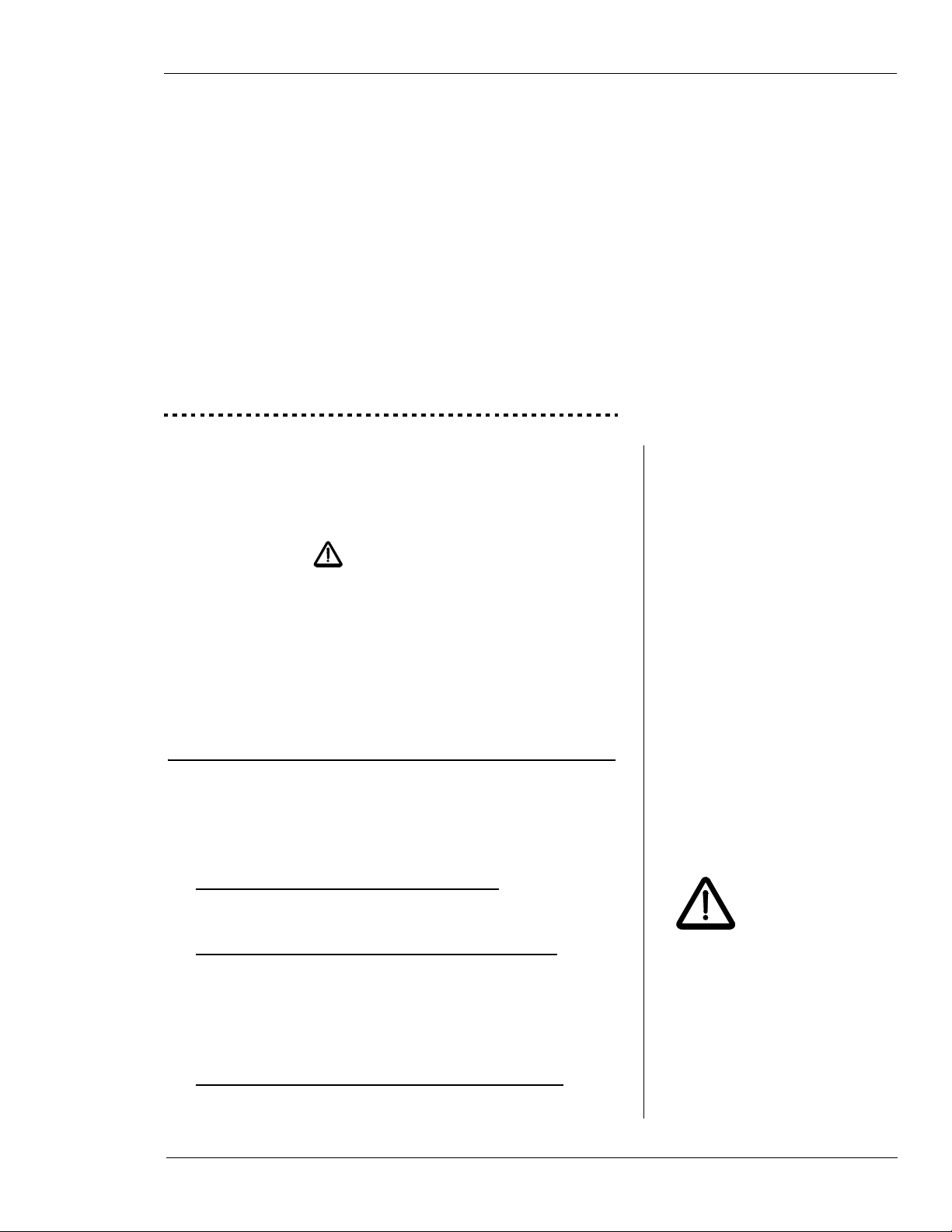
Figure 3-1 illustrates the components of the window cutter.
E.H. Wachs Part No. 06-030-MAN, Rev. 2-0709 9
Window Cutter
Radial gearbox Drive control lever
Chain tensioning
Feed select
gearbox
nut
Spindle
motor
Stabilizing
wedges
Manifold
Cutter
feed nut
Spindle
assembly
Spindle
assembly
Axial
drive
lock nut
screw
End support
plate
Radial drive
sprocket
Radial drive
sprocket
End support
plate
Figure 3-1. Window cutter components
10 Part No. 06-030-MAN, Rev. 2-0709 E.H. Wachs

Chapter 3, Introduction to the Equipment: Requirements
Starter box
Filter housing
Fluid reservoir Tank heater
Motor
Hydraulic Power Unit (HPU)
Figure 3-2 illustrates the hydraulic power unit (HPU) provided with the window cutter.
Figure 3-2. Hydraulic power unit provided with the
window cutter.
REQUIREMENTS
Handling
The window cutter weighs approximately 400 lbs (182 kg).
You will need a hoist or crane to move it and position it on
the pipe for cutting.
The machine has four removable lift hooks installed on its
frame. To position the machine horizontally, use all four
hooks. T o position the machine vertically, use the two hooks
at the top end of the frame.
CAUTION
Do not attempt to lift or move
the window cutter by hand.
Use a hoist or crane.
E.H. Wachs Part No. 06-030-MAN, Rev. 2-0709 11
Window Cutter
Figure 3-3. Two lift hooks are provided at each end of
the frame for lifting the window cutter. The hooks are
in threaded holes and can be removed.
Power Source
The hydraulic power unit for the window cutter provides 10
gpm (38 lpm) flow at 2,000 psi. The HPU operates on 230
V electric power at 28.4 amps.
SPECIFICATIONS
Length: 63” (160 cm)
Width: 31” (79 cm)
Height: 13” (33 cm)
Radial Clearance: 16.5” (42 cm)
Weight: approx. 400 lbs (180 kg)
Max. Axial Feed: 36”
Axial Feed Rate: 6 inches per minute
Max. Radial Feed:360°
Radial Feed Rate:6 inches per minute
Blade RPM: 40-160 rpm
Tooling: 6” diameter slitting blade
5” diameter beveling blade
12 Part No. 06-030-MAN, Rev. 2-0709 E.H. Wachs
ACCESSORIES
• Guide rings for vertical pipe—16”, 18”, and 20”
Chapter 3, Introduction to the Equipment: Accessories
Figure 3-4. Guide ring for cutting on vertical pipe
• Radial cut support clamp
Figure 3-5. Support clamp for r educing vibration dur ing radial cuts
E.H. Wachs Part No. 06-030-MAN, Rev. 2-0709 13

Window Cutter
14 Part No. 06-030-MAN, Rev. 2-0709 E.H. Wachs

Chapter 4
Assembly, Disassembly, and Storage
Chapter 4, Assembly, Disassembly, and Storage
The window cutter is shipped fully assembled from the factory in a shipping/storage crate.
REMOVING THE MACHINE FROM THE SHIPPING/STORAGE CRATE
You will need to use a crane to pick up the window cutter.
Screw the lift hooks into the window cutter frame if
1.
they are not already in place.
Position the crane above the crate.
2.
Attach a chain or cable to each of the four lift hooks
3.
on the machine, and attach the other ends to the crane.
Raise the crane until the cables or chains are taut, then
4.
slowly lift the machine. Make sure that the machine is
fairly level and that it does not catch against the side
of the crate.
In This Chapter
REMOVING THE MACHINE FROM
THE SHIPPING/STORAGE CRATE
ENVIRONMENTAL
R
EQUIREMENTS
LONG-TERM STORAGE
Always lift the machine out of
the case using all four hooks.
If you will be mounting it on a
vertical pipe, set it down on a
flat surface first and lift it from
there with the two top hooks.
Make sure the crane hook is
centered over the window
cutter before lifting it.
You can mount the machine directly on a horizontal
5.
pipe as described in Chapter 5. If you are mounting it
on a vertical pipe, first set it down on a level surface
and detach the hooks from the bottom end of the
machine.
E.H. Wachs Part No. 06-030-MAN, Rev. 2-0709 15

Window Cutter
ENVIRONMENTAL REQUIREMENTS
The window cutter can be operated in any environment,
including undersea. If used underwater, it is especially
important that you keep it well lubricated, and that you
clean and oil it after each use.
The hydraulic power unit can get wet without damage but
should not be operated in standing water.
LONG-TERM STORAGE
Clean the machine thoroughly before storage. If it has been
used undersea, spray it with fresh water to remove salt residue. Remove the cutting blade from the machine.
Oil all machined surfaces and grease the machine according
to the instructions in Chapter 6.
Secure the machine in its crate. If possible, store it in a noncorrosive atmosphere away from salt water.
16 Part No. 06-030-MAN, Rev. 2-0709 E.H. Wachs

Chapter 5
Operating Instructions
Chapter 5, Operating Instructions
In This Chapter
CONFIGURING THE MACHINE
Install the Tracking Wheels
The window cutter moves radially around the pipe on four
tracking wheels, two on each end of the frame. There are
four positions for the tracking wheels, depending on the
diameter of the pipe you are cutting.
CONFIGURING THE MACHINE
INSTALLING THE MACHINE
CUTTING THE WINDOW
Figure 5-1. There are four mounting positions on the
frame for the tracking wheels. Table 1 describes how
to set the wheels correctly for the size of the pipe you
are cutting. (Note that the 3/16” spacer is required for
some pipe sizes as indicated in Table 1.)
E.H. Wachs Part No. 06-030-MAN, Rev. 2-0709 17

Window Cutter
Table 1: Tracking Wheel Mounting Positions for Various Pipe Sizes
Pipe Size (inch) 6 8 10 12 14 16 18 20 22 24 26 28 30 32 34 36 38 42 48
Wheel Position 4 4 3 3 3 3 2 2 2 2 2 1 1 1 1 1 1 1 1
Space Required Y Y Y Y Y Y Y Y
Table 2: Chain Length for Various Pipe Sizes
Pipe Size (inch) 6 8 10 12 14 16 18 20 22 24 26 28 30 32 34 36 38 42 48
Chain Length (in) 53 58 63 68 71 76 81 87 92 98 103 109 115 120 126 132 150 150 168
Add Links:
2 inch 22 11 211
3 inch 111 2 1
5 inch 1 1 1 1 1 1 1 1 1 1 1
10 inch 1 1 1 1 1 1 1 1
20 inch 11112 1122
50 inch 111111112
Note that the orientation of the wheel
blocks is reversed
for positions 3 and 4.
Attach the tracking wheels at the indicated position using
one 3/8-16 x 1-1/2” socket head cap screw per block.
Tighten the screws with a hex wrench.
Setting the Chain Length
The mounting/drive chains are supplied with links of various sizes to extend them to the length required for the pipe
you are cutting. The standard chains are 53 inches long;
Table 2 describes the links required for each pipe size.
Make sure both
chains are the
same length before
you install them on the
machine.
18 Part No. 06-030-MAN, Rev. 2-0709 E.H. Wachs
Attach the required links to each chain using the supplied
master links or pins. Leave the ends of the chains disconnected; you will need the chain open to install it on the window cutter after you have the machine in place on the pipe.

Chapter 5, Operating Instructions: Installing the Machine
Pipe Side
INSTALLING THE MACHINE
Mounting on Horizontal Pipe
Always use a crane or hoist to lift and move the window
cutter.
Before lifting or moving the machine, do the following:
• Disconnect all hoses from the machine.
• Make sure the cutting head is fully retracted.
• Make sure the mounting chains are off the machine.
If necessary, install all four lift hooks by screwing
1.
them into the window cutter’s frame.
Position the crane over the center of the window cut-
2.
ter.
Attach a chain or cable to each lift hook and connect
3.
them to the crane.
Raise the crane slowly to lift the machine. Position the
4.
machine over the pipe at the cutting location and
lower it onto the pipe.
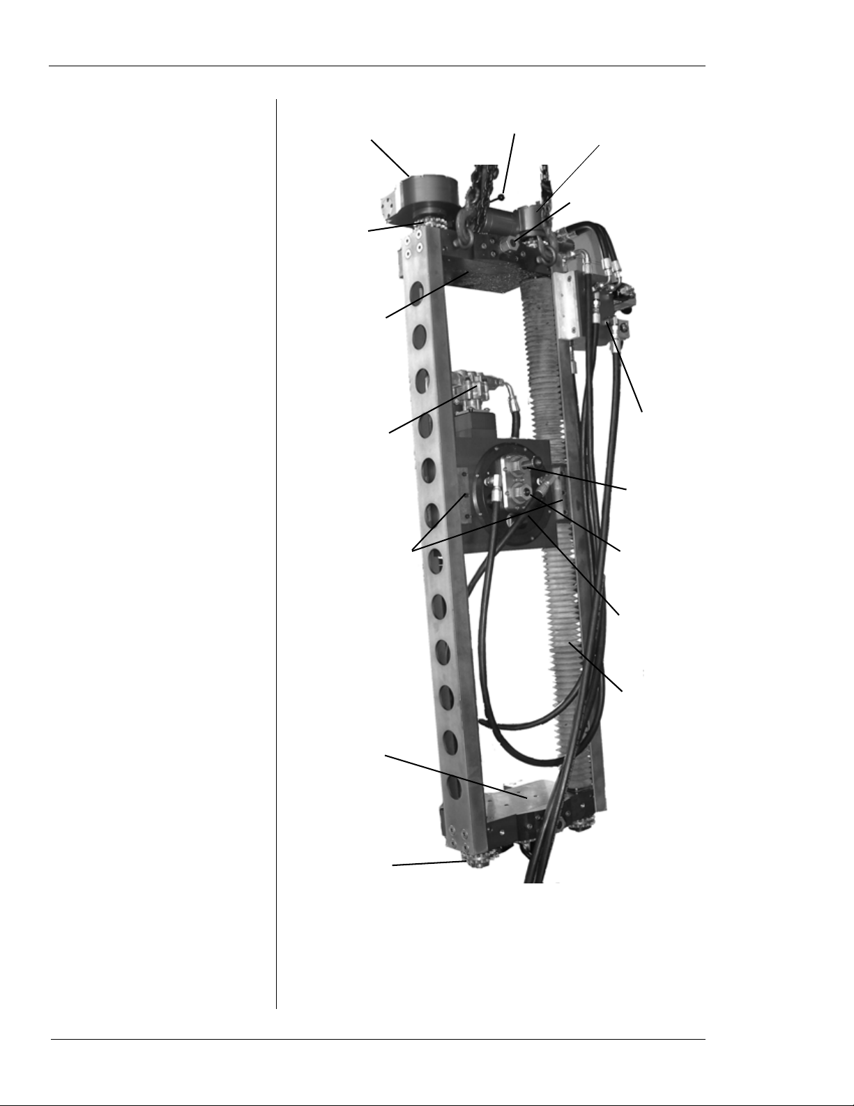
Wrap one of the mounting chains around the pipe at
5.
one end of the window cutter and thread it through the
drive sprockets as shown in Figure 5-10.
Leave the crane
attached to the
machine and supporting its weight until you
have the mounting chains
installed and tightened.
Figure 5-2. Thread the chain over the outside sprockets and between the inside sprocket and the pipe.
Connect the ends of the chain with the supplied pin.
6.
E.H. Wachs Part No. 06-030-MAN, Rev. 2-0709 19

Window Cutter
Have one person
hold the chain
straight while the
other person tightens it.
Make sure the chain is straight around the pipe.
7.
Tighten the chain until it is snug by turning the chain
tensioning nut clockwise, as shown in Figure 5-11.
Figure 5-3. Tighten the tensioning nut until the chain
is snug.
Install the chain at the other end in the same manner.
8.
Tighten the chain by turning the chain tensioning nut
9.
counter-clockwise.
Figure 5-4. Turn the tensioning nut counter-clockwise
to tighten the chain.
20 Part No. 06-030-MAN, Rev. 2-0709 E.H. Wachs

Turn the nut until you can see the red indicator line on
Indicator line
10.
the screw, as shown in Figure 5-13.
Chapter 5, Operating Instructions: Installing the Machine
Figure 5-5. The red indicator line is on the screw
inside the tensioner cover plate. Tighten the nut until
you can see the line.
Tighten the first tensioning nut until you can see the
11.
red indicator line on the screw.
Lower the crane and remove the lift chains from the
12.
window cutter frame
Mounting on Vertical Pipe
The window cutter can be installed with either end up on a
vertical pipe. Typically, you will install it with the controls
at the top, to give the most clearance below the machine.
Always use a crane to lift and move the window cutter.
Mounting the Guide Ring
The guide ring mounts on the pipe at the top of the window
cutter to support the machine’ s weight and ensure a straight
radial cut. Mounting the guide ring will require two people.
E.H. Wachs Part No. 06-030-MAN, Rev. 2-0709 21

Window Cutter
You can specialorder guide rings
for other pipe
sizes.
Guide rings for 16”, 18”, and 20” pipes are supplied with
the window cutter.
If necessary, take the two halves of the guide ring
1.
apart by removing the screws.
Put the halves of the guide ring together over the pipe
2.
at the location where the top of the machine will be
located. The support flange (thicker side of the ring)
must be on the bottom, as shown in fig.
Figure 5-6. Hold both halves of the guide ring on the
pipe and insert the screws through the brackets. Put
the nuts on the screws.
Insert the screws on both sides of the ring. Tighten
3.
them securely with a 15/16” wrench or socket.
Figure 5-7. Tighten the nuts on the guide ring screws
securely.
22 Part No. 06-030-MAN, Rev. 2-0709 E.H. Wachs

Mounting the Window Cutter
You will only need two lift hooks on the window cut-
1.
ter frame. Install the hooks at the end of the frame that
will be on top.
Position the crane over the window cutter.
2.
Attach a chain or cable to each lift hook and connect
3.
them to the crane.
Lift the window cutter slowly until the entire machine
4.
is off the floor.
Position the window cutter so that the tracking wheels
5.
at the top are just above the guide ring on the pipe.
Chapter 5, Operating Instructions: Installing the Machine
Figure 5-8. Set the top of the machine against the
pipe, with the tracking wheels on against the pipe and
on top of the guide ring.
Lower the machine gently so that the wheels are rest-
6.
ing on top of the guide ring.
Wrap a binding strap around the pipe and the middle
7.
of the window cutter. Tighten the strap to pull the
machine against the pipe.
E.H. Wachs Part No. 06-030-MAN, Rev. 2-0709 23
top of the guide ring.
Make sure the
wheels are against
the pipe and are on

Window Cutter
Pipe Side
Figure 5-9. Use a binding strap around the pipe and
center of the machine to pull it snug against the pipe.
Wrap one of the mounting chains around the pipe at
8.
the top of the window cutter (about six inches above
the guide ring) and thread it through the drive gears as
shown in Figure 5-10.
Figure 5-10. Thread the chain over the outside gears
and between the inside gear and the pipe.
Connect the ends of the chain with the supplied pin.
9.
Have one person
hold the chain
straight while the
other person tightens it.
24 Part No. 06-030-MAN, Rev. 2-0709 E.H. Wachs
Make sure the chain is straight and parallel with the
10.
guide ring. Tighten the chain until it is snug by turning
the chain tensioning nut clockwise, as shown in
Figure 5-11.

Figure 5-11. Tighten the tensioning nut on the top
chain until the chain is snug.
Install the bottom chain in the same manner as the top
11.
chain.
Chapter 5, Operating Instructions: Installing the Machine
Tighten the bottom chain by turning the chain tension-
12.
ing nut counter-clockwise.
Figure 5-12. Turn the bottom tensioning nut counterclockwise to tighten the chain.
Turn the nut until you can see the red indicator line on
13.
the screw, as shown in Figure 5-13.
E.H. Wachs Part No. 06-030-MAN, Rev. 2-0709 25

Window Cutter
Indicator line
Figure 5-13. The red indicator line is on the screw
inside the tensioner cover plate. Tighten the nut until
you can see the line.
Tighten the top tensioning nut until you can see the
14.
red indicator line on the screw.
Remove the binding strap.
15.
Lower the crane and remove the lift chains from the
16.
window cutter frame.
Connect Power Supply
Connect the hoses from the power unit to the connec-
1.
tors on the window cutter manifold.
CUTTING THE WINDOW
Horizontal Pipe
To cut the pipe window, you will first make the two axial
cuts along the length of the pipe. Then perform the radial
cuts around the pipe’s circumference. See the diagram in
Figure 5-14.
26 Part No. 06-030-MAN, Rev. 2-0709 E.H. Wachs

Chapter 5, Operating Instructions: Cutting the Window
CUT 4
CUT 1
CUT 2
CUT 3
.
Figure 5-14. For a horizontal pipe, cut the pipe window as shown in the diagram. Perform both axial cuts
first, then make the radial cuts at the ends.
Vertical Pipe
When window cutting on a vertical pipe, perform the side
and bottom cuts first, then the top cut. This keeps the cutter
above the fall-off piece on the final cut. See the diagram in
Figure 5-16.
Figure 5-15. Perform the illustrated cut sequence
when using the window cutter on a vertical pipe.
E.H. Wachs Part No. 06-030-MAN, Rev. 2-0709 27

Window Cutter
(Center)
Neutral
Radial
Drive
Axial
Drive
Machine Controls
There are three levers that control machine motion:
• The drive control lever at the end of the machine. This
lever has three positions, as shown in Figure 5-16.
Figure 5-16. The photo shows the drive control lever
at the bottom of the machine; directions are reversed
when the controls are at the top.
• The spindle drive lever, which turns the blade spindle on
and off, as shown in Figure 5-17.
• The motion drive lever, which has three positions, as
shown in Figure 5-17.
28 Part No. 06-030-MAN, Rev. 2-0709 E.H. Wachs

Chapter 5, Operating Instructions: Cutting the Window
On
Up/
Down/
Off
CCW
CW
Figure 5-17. The spindle (cutting) drive is on the top
in this orientation (on the shorter manifold block). The
motion drive lever is on the bottom (on the taller manifold block).
When the spindle drive is engaged, the motion drive is automatically in cutting feed (slow) mode. When the spindle is
disengaged, the motion drive is in rapid feed mode.
E.H. Wachs Part No. 06-030-MAN, Rev. 2-0709 29

Window Cutter
Rapid Feed Control
Cutting Feed Control
Spindle Drive Control
Flow Control Valves
There are flow control valves for the drives on the manifold.
These are illustrated in Fig.
Figure 5-18. Use the knobs to adjust the flow control
valves for the drives.
To adjust the flow control valve, loosen the set nut behind
the valve knob, turn the knob, then tighten the set nuts.
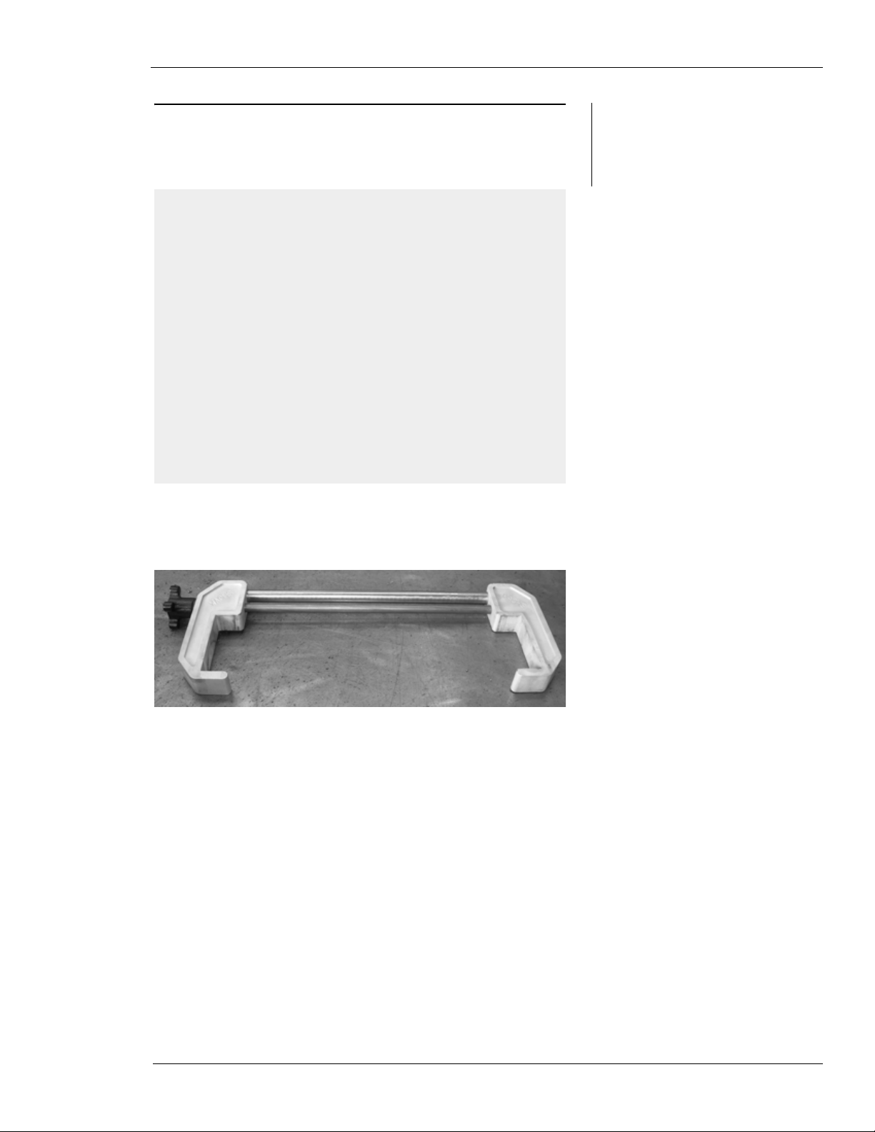
Radial Cut Stabilizing Clamp
A stabilizing clamp is provided to reduce vibration when
making a radial cut with the machine head near the center of
the window cutter frame.
30 Part No. 06-030-MAN, Rev. 2-0709 E.H. Wachs

Chapter 5, Operating Instructions: Cutting the Window
Center
Nut
Figure 5-19. The stabilizing clamp attaches across
the frame at the cutting head to reduce vibrations during a radial cut.
Rotating the Cutter Head
The entire cutter head rotates to set the cutting direction.
Use the following procedure to rotate the head.
Loosen the center nut on the cutter head.
1.
Figure 5-20. Loosen the center nut (top) to allow the
cutter head to turn.
E.H. Wachs Part No. 06-030-MAN, Rev. 2-0709 31
Window Cutter
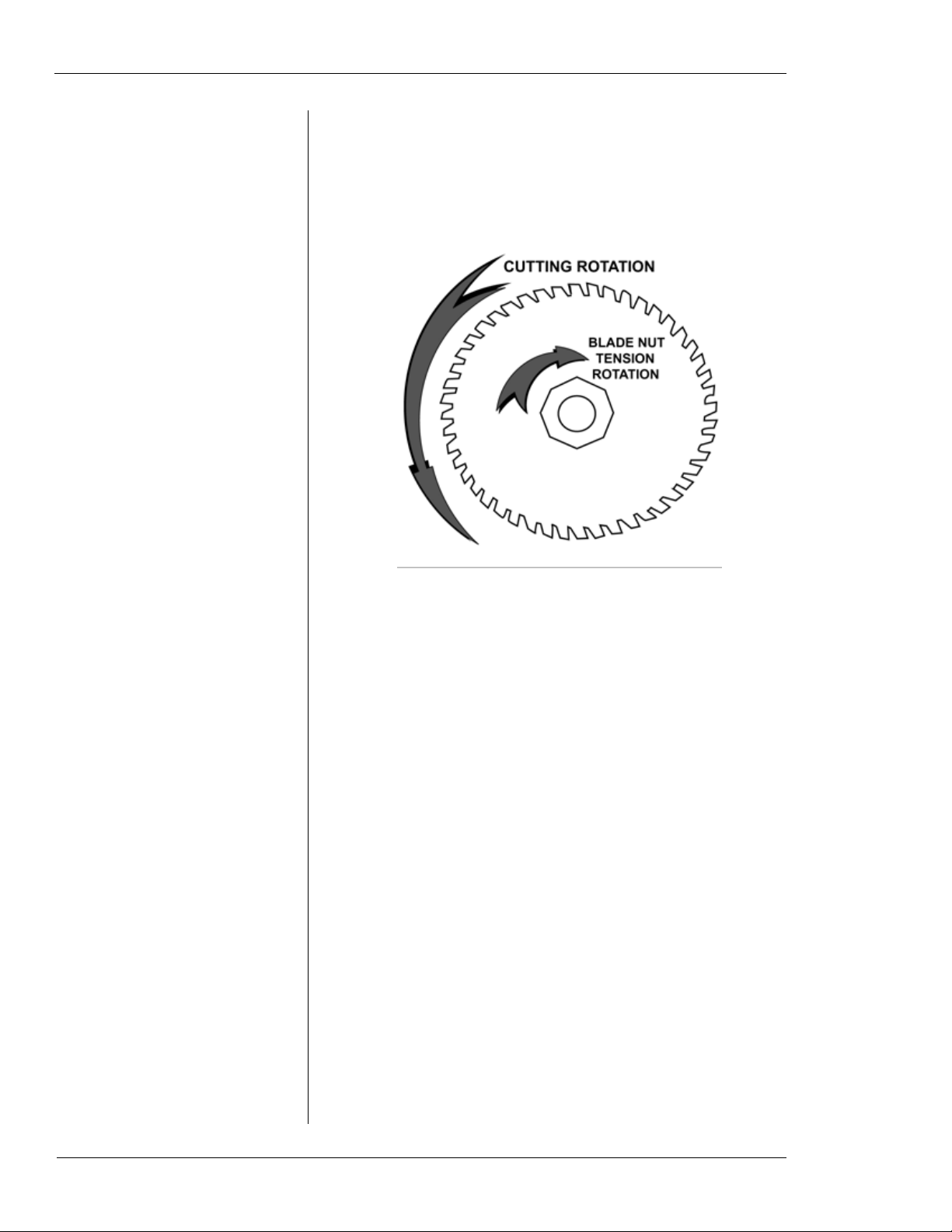
Turn the head to the desired cutting direction.
2.
IMPORTANT: Make sure the blade is oriented correctly for the direction you are cutting, as illustrated in
Figure 5-21.
Figure 5-21. Make sure the blade is oriented to cut in
the cutting direction indicated.
Feeding the Cutter into the Pipe
Before engaging either the axial or radial motion drive for
cutting, first feed the cutter blade into the pipe.
Make sure the spindle drive lever is in the OFF posi-
1.
tion, and the motion drive lever is in the NEUTRAL
(center) position.
Turn on the hydraulic power unit and turn on power to
2.
the window cutter with the HPU control pendant.
Use the drive select lever at the end of the machine
3.
and the motion drive lever on the manifold to position
the blade where you want to start cutting.
If necessary, rotate the cutter head to the correct orien-
4.
tation as described in the previous section.
Set the drive select lever for the drive motion (axial or
5.
radial) that you will be cutting.
32 Part No. 06-030-MAN, Rev. 2-0709 E.H. Wachs

Put the spindle drive lever into the ON position to start
Spindle
Feed Nut
6.
the spindle drive motion.
Using the supplied 1-3/8” socket, turn the spindle feed
7.
nut on the cutter head counter-clockwise to feed the
blade into the pipe.
Chapter 5, Operating Instructions: Cutting the Window
Figure 5-22. Turn the spindle feed nut counter-clockwise to feed the blade into the pipe.
Feed the blade in slowly. If the blade starts to chatter,
8.
stop for a few seconds, then resume feeding at a
slower rate.
Feed the blade in until you have penetrated the pipe
9.
wall. Continue feeding as far as you can without cutting internal structures in the pipe.
Remove the socket from the spindle feed nut.
10.
With the spindle drive still engaged and the blade turn-
11.
ing, use the motion drive lever to start making the cut.
The motion drive will automatically be in cutting
(low-speed) mode while the spindle drive is running.
Continue until the cut is complete. Move the motion
12.
drive lever to the NEUTRAL position to stop the drive
motion.
E.H. Wachs Part No. 06-030-MAN, Rev. 2-0709 33

Window Cutter
Using the 1-3/8” socket, turn the spindle feed nut
13.
clockwise to retract the blade from the pipe. Be sure to
retract the blade completely.
Turn off the spindle drive motion.
14.
Position the cutter head for the next cut using the drive
15.
select lever and the motion drive lever. If necessary,
rotate the cutter head as described in the previous section.
34 Part No. 06-030-MAN, Rev. 2-0709 E.H. Wachs

Chapter 6
Routine Maintenance
Grease the machine using Phillips 66 X/C 22CF Aviation
Grease or equivalent.
Chapter 6, Routine Maintenance
E.H. Wachs Part No. 06-030-MAN, Rev. 2-0709 35

Window Cutter
36 Part No. 06-030-MAN, Rev. 2-0709 E.H. Wachs

Chapter 7
Service and Repair
Refer to the drawings and parts lists in Chapter 8 for service
and repair information on window cutter components.
Chapter 7, Service and Repair
E.H. Wachs Part No. 06-030-MAN, Rev. 2-0709 37

Window Cutter
38 Part No. 06-030-MAN, Rev. 2-0709 E.H. Wachs

Chapter 8
Parts Lists and Drawings
Refer to the drawing and the parts list on the following
pages for ordering spare and replacement parts.
Chapter 8, Parts Lists and Drawings
E.H. Wachs Part No. 06-030-MAN, Rev. 2-0709 39

Chapter 8: Parts Lists and Drawings Window Cutter
40 06-030-MAN E.H. Wachs Company

Window Cutter Chapter 8: Parts Lists and Drawings
E.H. Wachs Company 06-030-MAN 41

Chapter 8: Parts Lists and Drawings Window Cutter
42 06-030-MAN E.H. Wachs Company

Window Cutter Chapter 8: Parts Lists and Drawings
E.H. Wachs Company 06-030-MAN 43

Chapter 8: Parts Lists and Drawings Window Cutter
44 06-030-MAN E.H. Wachs Company

Window Cutter Chapter 8: Parts Lists and Drawings
E.H. Wachs Company 06-030-MAN 45

Chapter 8: Parts Lists and Drawings Window Cutter
46 06-030-MAN E.H. Wachs Company

Window Cutter Chapter 8: Parts Lists and Drawings
E.H. Wachs Company 06-030-MAN 47

Chapter 8: Parts Lists and Drawings Window Cutter
48 06-030-MAN E.H. Wachs Company

Chapter 9
Accessories and Spare Parts
The following accessories are provided with the window
cutter.
Chapter 9, Accessories and Spare Parts
• Guide rings for vertical pipe—16”, 18”, and 20”
Figure 9-1. Guide ring for cutting on vertical pipe
E.H. Wachs Part No. 06-030-MAN, Rev. 2-0709 49

Window Cutter
• Radial cut support clamp
Figure 9-2. Support clamp for r e ducing vibration during radial cuts
50 Part No. 06-030-MAN, Rev. 2-0709 E.H. Wachs

Chapter 10
Ordering Information
Chapter 10, Ordering Information
To place an order, request service, or get more detailed
information on any E.H. Wachs products, call us at one of
the following numbers:
U.S. 800-323-8185
International: 847-537-8800
You can also visit our Web site at:
www.ehwachs.com
ORDERING REPLACEMENT PARTS
When ordering parts, refer to the parts lists in this chapter.
Please provide the part description and part number for all
parts you are ordering.
REPAIR INFORMATION
In This Chapter
ORDERING REPLACEMENT
ARTS
P
REPAIR INFORMATION
WARRANTY INFORMATION
RETURN GOODS ADDRESS
Please call us for an authorization number before returning
any equipment for repair or factory service. We will advise
you of shipping and handling. When you send the equipment, please include the following information:
• Your name/company name
• Your address
• Your phone number
• A description of the problem or the work to be done.
E.H. Wachs Part No. 06-030-MAN, Rev. 2-0709 51

Window Cutter
Before we perform any repair, we will estimate the work
and inform you of the cost and the time to complete it.
WARRANTY INFORMATION
Enclosed with the manual is a warranty card. Please fill out
the registration card and return to E.H. Wachs. Retain the
owner’s registration record and warranty card for your
information.
RETURN GOODS ADDRESS
Return equipment for repair to the following address.
E.H. Wachs
600 Knightsbridge Parkway
Lincolnshire, Illinois 60069 USA
52 Part No. 06-030-MAN, Rev. 2-0709 E.H. Wachs
 Loading...