

Wachendorff WDGA CANopen Technical Manual
-
Technical Manual
WDGA with CANopen-Interface
© Wachendorff Automation GmbH & Co. KG I Rev.1.24
Imprint
Wachendorff Automation GmbH & Co. KG
Industriestrasse 7
D-65366 Geisenheim
Tel: +49 (0) 67 22 / 99 65 25
Fax: +49 (0) 67 22 / 99 65 70
E-Mail: wdg@wachendorff.de
Homepage: www.wachendorff-automation.de
Wiesbaden District Court HRA 8377, VAT ID: DE 814567094
Managing Director: Robert Wachendorff
Guarantee waiver, right of amendment, copyright protection:
The company Wachendorff Automation assumes no liability and provides no guarantee
for the correctness of this manual's contents or for any resulting direct or indirect
damages. In the interests of continuous innovation and cooperation with our
customers, we reserve the right to change technical data or content at any time.
The company Wachendorff Automation claims copyright protection for this manual. It
may not be modified, extended, reproduced, or forwarded to third parties without our
prior written consent.
Comments:
Should you have any suggested corrections, comments or requests for change, we
invite you to submit them to us. Please send your comments to: wdg@wachendorff.de

Technical Manual
WDGA with CANopen-Interface
Inhaltsverzeichnis
© Wachendorff Automation GmbH & Co. KG
II
Rev.1.24
1 Introduction ..................................................................................... 1
1.1 Encoder types................................................................................................ 1
1.2 About this manual .......................................................................................... 1
1.2.1 Symbols .................................................................................................. 2
1.3 Specifications ................................................................................................ 2
2 Safety information ........................................................................... 3
2.1 General safety information ............................................................................ 3
2.2 Intended use .................................................................................................. 3
2.3 Safe working .................................................................................................. 4
2.4 Disposal ......................................................................................................... 4
3 Device description ........................................................................... 5
3.1 Basic encoder design .................................................................................... 5
3.2 Predefined Connection Settings .................................................................... 5
3.3 LED status indicator and signal codes ........................................................... 6
4 Quick start ........................................................................................ 8
4.1 CAN network integration ................................................................................ 8
4.2 SDO command to set the node ID ................................................................. 8
4.3 Setting-up the encoder .................................................................................. 9
5 General information about CAN ................................................... 11
5.1 CAN physical and transport layer ................................................................ 11
5.2 CANopen ..................................................................................................... 13
5.3 Specifications and profiles ........................................................................... 14
5.3.1 Overview ............................................................................................... 14
5.3.2 Mechanisms of communication ............................................................. 14
5.3.3 Object dictionary ................................................................................... 15
5.4 Network management (NMT) ...................................................................... 16
5.5 Heartbeat and Node-Guarding .................................................................... 17
5.6 Emergency messages ................................................................................. 18
6 WDGA object dictionary ................................................................ 19
6.1 Communication objects ............................................................................... 19
6.2 Device specific objects ................................................................................ 22
6.3 Manufacturer specific objects ...................................................................... 28
7 Object description ......................................................................... 30
7.1 Network management (NMT) commands .................................................... 30

Technical Manual
WDGA with CANopen-Interface
Inhaltsverzeichnis
© Wachendorff Automation GmbH & Co. KG
III
Rev.1.24
7.2 Heartbeat protocol ....................................................................................... 31
7.3 Emergency messages (EMCY) ................................................................... 32
7.4 Error Objects ............................................................................................... 33
7.4.1 Manufacturer status register ................................................................. 33
7.4.2 Alarms ................................................................................................... 34
7.4.3 Warnings ............................................................................................... 34
7.5 Electronic cam switch (CAM) ....................................................................... 34
7.5.1 CAM-state-register ................................................................................ 34
7.5.2 CAM-enable-register ............................................................................. 35
7.5.3 CAM-polarity-register ............................................................................ 35
7.5.4 CAM-Low-Limit ..................................................................................... 35
7.5.5 CAM-High-Limit ..................................................................................... 36
7.5.6 CAM-Hysteresis .................................................................................... 36
7.6 Device profile ............................................................................................... 36
7.7 SYNC .......................................................................................................... 36
7.8 Encoder designation .................................................................................... 36
7.9 Error behaviour ............................................................................................ 37
7.10 NMT start-up behaviour ............................................................................ 37
7.11 Bus-Off Auto-Reset .................................................................................. 37
7.12 Customer Data ......................................................................................... 38
7.13 Temperature ............................................................................................. 38
7.14 Verify Configuration .................................................................................. 38
8 Setting-up the encoder .................................................................. 39
8.1 Mechanical and electrical connection .......................................................... 39
8.2 Configuration via LSS .................................................................................. 41
8.2.1 General settings .................................................................................... 41
8.2.2 LSS configuration by "Switch Mode Global" .......................................... 41
8.2.3 LSS configuration by "Switch Mode Selective" ..................................... 42
8.2.4 End LSS configuration mode ................................................................ 43
8.2.5 Baudrate setting .................................................................................... 43
8.2.6 Node-ID setting ..................................................................................... 44
8.3 Configuration via SDO ................................................................................. 45
8.3.1 SDO access on objects ......................................................................... 45
8.3.2 SDO access on objects larger than 4 bytes .......................................... 47
8.3.3 Baudrate selection ................................................................................ 54

Technical Manual
WDGA with CANopen-Interface
Inhaltsverzeichnis
© Wachendorff Automation GmbH & Co. KG
IV
Rev.1.24
8.3.4 Node-ID selection ................................................................................. 55
8.3.5 Basic NMT commands .......................................................................... 56
8.4 Heartbeat settings ....................................................................................... 57
8.5 PDO Configuration ...................................................................................... 57
8.5.1 PDO parameters ................................................................................... 57
8.5.2 Synchronous PDO ................................................................................ 59
8.5.3 Asynchronous PDO .............................................................................. 59
8.5.4 Variable PDO-mapping ......................................................................... 60
8.6 Changing resolution and direction ............................................................... 63
8.7 Position preset ............................................................................................. 64
8.8 Position value filtering .................................................................................. 65
8.9 Change speed-integration and speed scaling ............................................. 65
8.10 Frequency limit ......................................................................................... 66
8.11 CAM-configuration.................................................................................... 66
8.12 Non-volatilely storage of parameters ........................................................ 68
8.12.1 Saving parameters into EEPROM ..................................................... 68
8.12.2 Restoring default parameters from EEPROM .................................... 69
9 Error diagnosis .............................................................................. 70
9.1 Encoder configurations ................................................................................ 70
10 Support ........................................................................................ 71

Technical Manual
WDGA with CANopen-Interface
List of figures
© Wachendorff Automation GmbH & Co. KG V Rev.1.24
List of figures
Figure 1.1: Encoder label ............................................................................................ 1
Figure 3.1: Encoder versions, shaft and hollow bore shaft ......................................... 5
Figure 3.2: LED indications 1 ...................................................................................... 6
Figure 3.3: LED indications 2 ...................................................................................... 7
Figure 5.1: Example of the arbitration ....................................................................... 12
Figure 5.2: Bitstuffing ................................................................................................ 12
Figure 5.3: ISO-OSI-Modell ...................................................................................... 13
Figure 8.1: read object .............................................................................................. 45
Figure 8.2: write object ............................................................................................. 46
Figure 8.3: Segmented SDO read access ................................................................ 47
Figure 8.4: Initiate SDO read .................................................................................... 48
Figure 8.5: read SDO segment ................................................................................. 49
Figure 8.6: Segmented-SDO write access ................................................................ 50
Figure 8.7: Initiate SDO write .................................................................................... 51
Figure 8.8: write SDO segment ................................................................................ 53

Technical Manual
WDGA with CANopen-Interface
List of tables
© Wachendorff Automation GmbH & Co. KG
VI
Rev.1.24
List of tables
Table 3.1: CAN-Identifier ............................................................................................ 5
Table 4.1: SYNC-message ......................................................................................... 8
Table 4.2: SDO-write command to set Node-ID ......................................................... 9
Table 4.3: Node-ID in decimal and hexadecimal ........................................................ 9
Table 5.1: CAN baud rates und recommended cable length limits ........................... 13
Table 5.2: Draft Standards ........................................................................................ 14
Table 5.3: Structure of the object dictionary ............................................................. 15
Table 5.4: Available communication – Pre-Operational ............................................ 16
Table 5.5: Available communication – Operational ................................................... 17
Table 5.6: Available communication – Stopped ........................................................ 17
Table 6.1: Object dictionary 1000h – 100Dh ............................................................. 19
Table 6.2: Object dictionary 1010h – 1020h ............................................................. 20
Table 6.3: Object dictionary 1029h – 1A01h ............................................................. 21
Table 6.4: Object dictionary 1A02h – 1F80h ............................................................. 22
Table 6.5: Device specific objects 6000h –6008h ..................................................... 22
Table 6.6: Device specific objects 6009h –6310h ..................................................... 23
Table 6.7: Device specific objects 6311h –6322h ..................................................... 24
Table 6.8: Device specific objects 6323h –6334h ..................................................... 25
Table 6.9: Device specific objects 6335h –6504h ..................................................... 26
Table 6.10: Device specific objects 6505h –6510h ................................................... 27
Table 6.11: manufacturer specific objects 2100h –2500h ........................................ 28
Table 6.12: manufacturer specific objects 2502h –2504h ........................................ 29
Table 7.1: Structure of NMT-command..................................................................... 30
Table 7.2: Commands for NMT-command................................................................ 30
Table 7.3: Node-ID values for NMT-commands ....................................................... 30
Table 7.4: monitor external heartbeat ....................................................................... 31
Table 7.5: Example configuration of a consumer heartbeat...................................... 31
Table 7.6: Basic structure of an EMCY ..................................................................... 32
Table 7.7: Emergency error code list ........................................................................ 32
Table 7.8: Error register ............................................................................................ 32
Table 7.9: Info field list .............................................................................................. 33
Table 7.10: Manufacturer status register .................................................................. 33
Table 7.11: Alarms - Object 6503h ........................................................................... 34
Table 7.12: Warnings – Object 6505h ...................................................................... 34
Table 7.13: CAM-state-register – Value 89h ............................................................. 34
Table 7.14: CAM-state-register – Value 81h ............................................................. 34
Table 7.15: CAM-enable-register – Value 4Ah ......................................................... 35
Table 7.16: Example CAM-polarity-register .............................................................. 35
Table 7.17: Selection of encoder reaction on errors ................................................. 37
Table 7.18: Selection of start-up behaviour .............................................................. 37
Table 8.1: Pin and cable assignment ........................................................................ 40
Table 8.2: LSS-message .......................................................................................... 41
Table 8.3: Command to set encoder “Stopped“-Mode .............................................. 41
Table 8.4: LSS-Selective-Identification-Commands ................................................. 42
Table 8.5: Answer of encoder to LSS-Selective-Identification-Commands ............... 42

Technical Manual
WDGA with CANopen-Interface
List of tables
© Wachendorff Automation GmbH & Co. KG
VII
Rev.1.24
Table 8.6: End LSS configuration mode – Step 1 - store parameters ....................... 43
Table 8.7: End LSS configuration mode – Step 2 - Leave configuration mode......... 43
Table 8.8: set Baudrate ............................................................................................ 43
Table 8.9: Baudrate-Coding ...................................................................................... 43
Table 8.10: Answer of LSS-slave ............................................................................. 44
Table 8.11: set Node-ID............................................................................................ 44
Table 8.12: Example SDO master to encoder .......................................................... 45
Table 8.13: Example SDO answer ........................................................................... 45
Table 8.14: Command definitions ............................................................................. 46
Table 8.15: Example SDO send by master ............................................................... 46
Table 8.16: Example SDO answer ........................................................................... 46
Table 8.17: SDO read request on object 6008h ....................................................... 47
Table 8.18: Declaration of used abbreviations in Figure 8.4 ..................................... 48
Table 8.19: Confirm SDO read access of object 6008h ............................................ 48
Table 8.20: Declaration of used abbreviations in Figure 8.5 ..................................... 49
Table 8.21: read of first segment .............................................................................. 49
Table 8.22: answer with first segment ...................................................................... 49
Table 8.23: Request next segment ........................................................................... 50
Table 8.24: Answer with next segment ..................................................................... 50
Table 8.25: SDO write access of object 6009h ......................................................... 51
Table 8.26: Acknowledgement of write access of object 6009h ............................... 51
Table 8.27: Declaration of used abbreviations in Figure 8.7 ..................................... 52
Table 8.28: send first segment ................................................................................. 52
Table 8.29: Acknowledgement send by the encoder ................................................ 52
Table 8.30: Declaration of used abbreviations in Figure 8.8 ..................................... 53
Table 8.31: send next segment ................................................................................ 53
Table 8.32: Acknowledgement send by the encoder ................................................ 54
Table 8.33: SDO command – set baudrate .............................................................. 54
Table 8.34: Baudrate-coding .................................................................................... 54
Table 8.35: Node-ID selection .................................................................................. 55
Table 8.36: Valid Node-IDs ....................................................................................... 55
Table 8.37: NMT command - Start remote node ...................................................... 56
Table 8.38: NMT command - Stop remote node ....................................................... 56
Table 8.39: NMT command - Enter Pre-Operational-state ....................................... 56
Table 8.40: NMT command - Reset node communication ........................................ 56
Table 8.41: NMT command - Reset remote node ..................................................... 56
Table 8.42: Example of heartbeat setting ................................................................. 57
Table 8.43: Structure of heartbeat message ............................................................. 57
Table 8.44: Heartbeat NMT-state-coding.................................................................. 57
Table 8.45: Default PDO configuration ..................................................................... 57
Table 8.46: Selectable PDO transmission types ....................................................... 58
Table 8.47: PDO-Deactivation .................................................................................. 58
Table 8.48: Example - PDO1 deactivation ................................................................ 58
Table 8.49: Parametrization of PDO1 Sub-Index 2 ................................................... 59
Table 8.50: Parametrization of PDO1 Sub-Index 2 ................................................... 59
Table 8.51: Parametrization of PDO1 Sub-Index 5 to 30ms ..................................... 59
Table 8.52: Parametrization of PDO1 Sub-Index 2 ................................................... 60

Technical Manual
WDGA with CANopen-Interface
List of tables
© Wachendorff Automation GmbH & Co. KG
VIII
Rev.1.24
Table 8.53: Parametrization of PDO1 Sub-Index 5 ................................................... 60
Table 8.54: Example of a mapping-table .................................................................. 60
Table 8.55: Structure of PDO1 (content -> Table 8.54) ............................................ 61
Table 8.56: Mapping parameter ................................................................................ 61
Table 8.57: Mapping position value .......................................................................... 62
Table 8.58: Mapping speed value ............................................................................. 62
Table 8.59: Mapping acceleration value ................................................................... 62
Table 8.60: Mapping parameter – activate new mapping ......................................... 62
Table 8.61: Counting direction and scaling parameters ............................................ 63
Table 8.62: Example setting operating parameters .................................................. 63
Table 8.63: Change of singleturn-resolution by SDO ............................................... 64
Table 8.64: Change of total measuring range by SDO ............................................. 64
Table 8.65: Set position preset ................................................................................. 64
Table 8.66: Check current position ........................................................................... 65
Table 8.67: Example CAM-configuration .................................................................. 66
Table 8.68: Enable first three cams .......................................................................... 66
Table 8.69: CAM-High-Limit 1 .................................................................................. 67
Table 8.70: CAM-High-Limit 2 .................................................................................. 67
Table 8.71: CAM-High-Limit 3 .................................................................................. 67
Table 8.72: CAM-Low-Limit 1 ................................................................................... 67
Table 8.73: CAM-Low-Limit 2 ................................................................................... 67
Table 8.74: CAM-Low-Limit 3 ................................................................................... 67
Table 8.75: Saving parameters ................................................................................. 68
Table 8.76: Example – Save all parameters ............................................................. 68
Table 8.77: Restoring parameters ............................................................................ 69
Table 9.1: Error diagnosis – Encoder configuration .................................................. 70

Technical Manual
WDGA with CANopen-Interface
Glossary
© Wachendorff Automation GmbH & Co. KG
IX
Rev.1.24
autom.
automatic
approx.
approximately
CAN
Controller Area Network
CAN-ID
Main part of the arbitration of a CAN-frame
co
constant: parameter is read-only, doesn’t change
COB-ID
Communication Object identifier, specifying the CAN-ID and
additional parameters for the related communication object
comp.
Compare
DLC
Data Length Code
DS
Draft Standard
DSP
Draft Standard Proposal
dyn
dynamic; information changes depending on encoder features
EDS file
Electronic data sheet, standardised file describing a CANopen
device
EMC
Electromagnetic Compatibility
Encoder
here synonym for absolute rotary encoder
e.g.
for example (exempli gratia)
etc.
et cetera, and so on
GND
Ground
i*
Wildcard character for encoder specific information
i.e.
that is (id est)
Idx
Sub-Index
LED
Light Emitting Diode
LSB
Least Significant Bit/Byte
LSS
Layer Setting Services
MSB
Most Significant Bit/Byte
MT
Multiturn
n.n.
not necessary
NMT
Network management
Node-ID
Part of CAN-ID; number of the encoder in the CAN network
OSI
Open Systems Interconnection Reference Model
p.
Page reference
PDO
Process Data Object. Communication object for transmission
of process data
res.
reserved
Glossary

Technical Manual
WDGA with CANopen-Interface
Glossary
© Wachendorff Automation GmbH & Co. KG X Rev.1.24
ro
Read Only: but not constant
RTR
Remote Transmission Request
rw
Read/Write: parameter can be read and written
SDO
Service Data Object; communication object providing access
to all entries of the object dictionary
ST
Singleturn
SYNC
Synchronisations telegram
wo
Write Only
xxb
Mark that (xx) is a binary representation
xxd
Mark that (xx) is a decimal representation
xxh
Mark that (xx) is a hexadecimal representation
Technical Manual
WDGA with CANopen-Interface
1 - Introduction
© Wachendorff Automation GmbH & Co. KG 1 Rev.1.24
1 Introduction
1.1 Encoder types
This manual is assigned to the following Wachendorff Automation encoders:
WDGA CANopen
It applies to all WDGA CANopen with Revision Number (Software version) 1.18 and
less.
The Wachendorff Automation CANopen vendor id is: 0100 021Fh
The Wachendorff Automation product code is: WDGA= 5744 4741h
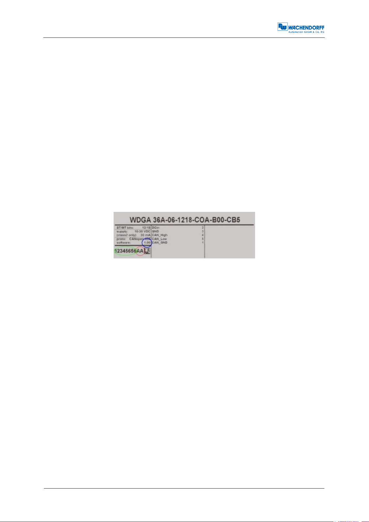
The revision number and the serial number vary for each individual encoder and can
be found on the encoder’s label:
Figure 1.1: Encoder label
In the figure 1.1 the revision number is marked blue (here: 1.00). The revision is
combined with a leading 0306 and fixed within the encoder firmware
(e.g. Rev. 1.00 = 0306 0100h; Rev. 1.06 = 0306 0106h).
The serial number is marked green (here: "12345656"). This decimal value transferred
into "hex" is used in the firmware (e.g. "12345656"="00BC 6138"h).
The hardware version is marked red (here: AA). The ASCII value transferred into hex
is the hardware revision coded in the corresponding CANopen object.
1.2 About this manual
This technical manual describes the configuration and mounting possibilities for
absolute-value encoders with a CANopen interface produced by Wachendorff
Automation. It supplements the other publicly available Wachendorff automation
documents, e.g. data sheets, assembly instructions, leaflets, catalogues and flyers.
Ensure that you read the manual before commissioning — check beforehand that you
have the latest version of the manual.
Technical Manual
WDGA with CANopen-Interface
1 - Introduction
© Wachendorff Automation GmbH & Co. KG 2 Rev.1.24
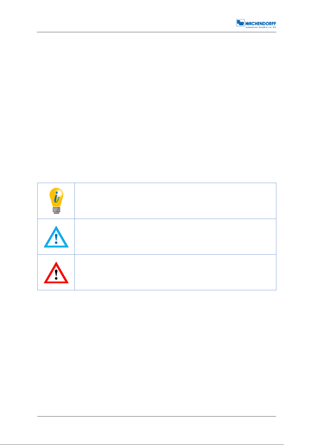
The INFO symbol indicates a section that contains particularly
important information for advanced use of the device.
The IMPORTANT symbol is shown next to a section of text that
describes a method for solving a particular problem.
The WARNING symbol indicates that the adjacent instructions
must be observed to ensure correct use of the device and to
protect the user against hazards.
When reading, pay particular attention to the information, important notices and
warnings that are marked with the corresponding symbols (see 1.2.1).
Section 4 Quick start shows a way how to configure the encoder in a very general
setting with minimal functionality. For optimal usage of the device, it is necessary to
read all the following information. Abbreviations and specific wording is explained at
the beginning of this manual.
This manual is intended for persons with technical knowledge in the handling of
sensors, CANopen interfaces and automation elements. If you do not have any
experience in this field, request the assistance of experienced personnel before
proceeding.
Keep the information provided with our product in a safe place so that you can refer to
it at a later date as necessary.
1.2.1 Symbols
1.3 Specifications
An encoder is a sensor that is designed to detect angular positions (singleturn) and
revolutions (multiturn). The measured data and variables are processed by the
encoder and provided as electrical output signals for the connected peripherals.
The interface and protocol for the communication between encoder and attached
equipment meets the CAN and CANopen specifications. The encoder is capable of
CAN 2.0A and CAN 2.0B. The implemented CANopen protocol meets the CiA 406
encoder profile.
For an easy configuration of the encoder, EDS files (electronic data sheet) are provided
at the download area at www.wachendorff-automation.com.
Technical Manual
WDGA with CANopen-Interface
2 - Safety information
© Wachendorff Automation GmbH & Co. KG 3 Rev.1.24
When commissioning the encoder, ensure that you observe the
assembly instructions, manual and data sheet.
Failure to observe the safety instructions may lead to
malfunctions, property damage and personal injury!
Observe the operating instructions provided by the machine's
manufacturer.
The encoder must not be operated outside the specified limit
parameters (see data sheet).
2 Safety information
2.1 General safety information
2.2 Intended use
Rotary encoders are components that are intended for installation in machines. Before
commissioning (operation in accordance with the intended use), it must be determined
that the machine as a whole corresponds to the EMC and Machine Directive.
A rotary encoder is a sensor that is designed to detect angular positions and
revolutions and must only be used for this purpose! Wachendorff Automation
manufactures and distributes encoders for use in non-safety-relevant industrial
applications.
Technical Manual
WDGA with CANopen-Interface
2 - Safety information
© Wachendorff Automation GmbH & Co. KG 4 Rev.1.24
All electrical connections must be tested before
commissioning.
Appropriate safety measures must be taken to ensure that no
persons are harmed and no damage to the system or operating
equipment occurs in the event of a failure or malfunction.
2.3 Safe working
The installation and mounting of the encoder must only be carried out by a qualified
electrician.
For the construction of electrical installations, all relevant national and international
regulations must be strictly observed.
Failure to commission the encoder correctly may result in malfunction or failure.
2.4 Disposal
Devices that are no longer needed or are defective must be disposed by the user in
proper compliance with the country-specific laws. It must be taken into consideration
that this is a special waste of electronics and that disposal is not permitted via normal
household waste.
There is no obligation by the manufacturer to take the device back. If you have any
questions regarding proper disposal, contact a disposal specialist in your area.
Technical Manual
WDGA with CANopen-Interface
3 - Device description
© Wachendorff Automation GmbH & Co. KG 5 Rev.1.24
Services
COB-ID
NMT
000h
SYNC
080h
EMCY
080h + Node-ID
PDO1(tx)
180h + Node-ID
PDO2(tx)
280h + Node-ID
PDO3(tx)
380h + Node-ID
SDO(rx)
600h + Node-ID
SDO(rx)
580h + Node-ID
3 Device description
3.1 Basic encoder design
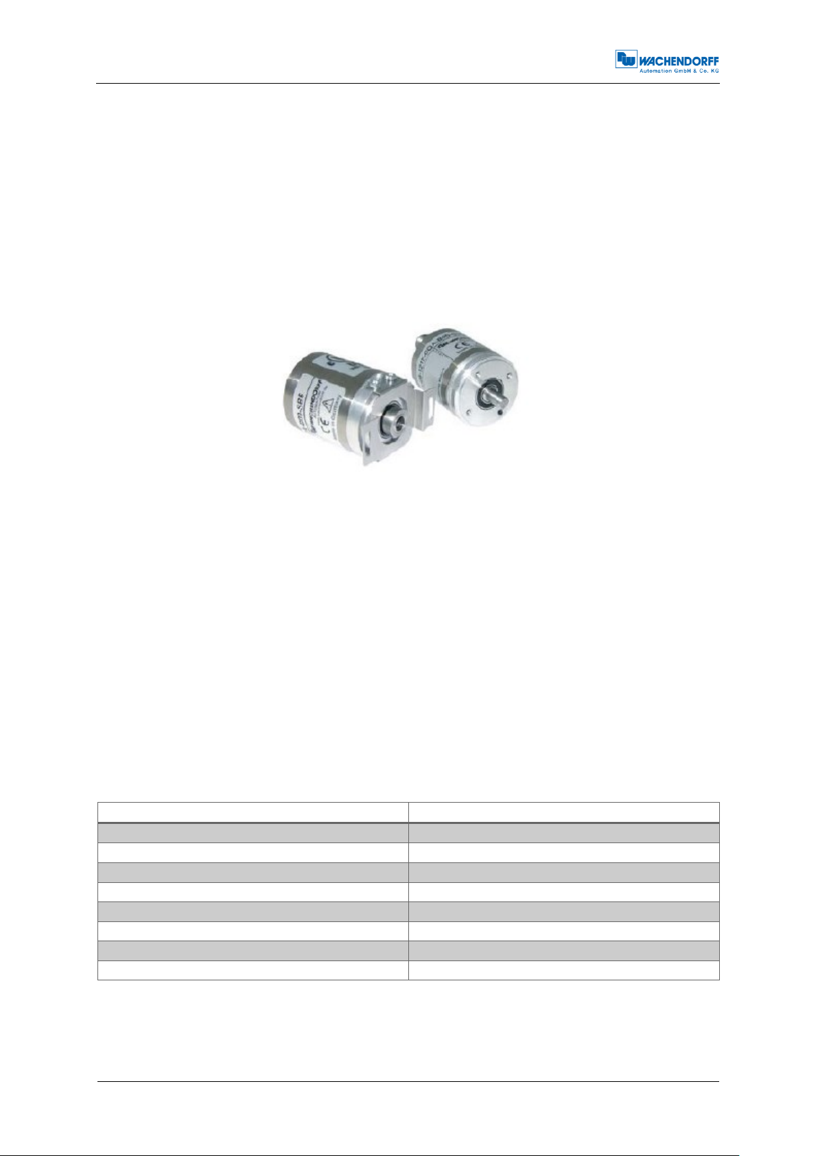
Wachendorff Automation WDGA encoders are available in different mechanical
versions. Key features are size and shape. The standard sizes are 36mm and 58mm
flange diameter. Different types of shapes according to shafts and flanges are
available. Examples of the different versions are shown in Figure 3.1:
Figure 3.1: Encoder versions, shaft and hollow bore shaft
The shaft or the hollow bore shaft will be connected to the rotating part of which the
angular position or rotation you want to measure. The encoder itself is mounted by
several tapped bores or torque supports.
A stub cable or M12 sized connector provides the electrical connection to the CANnetwork.
A bicolour status LED at the top indicates the different states of the encoder during use
and helps with configuration and troubleshooting.
3.2 Predefined Connection Settings
By default all WDGA encoders are set on Node-ID=127h and Baudrate=AutoDetection.
Table 3.1: CAN-Identifier
Technical Manual
WDGA with CANopen-Interface
3 - Device description
© Wachendorff Automation GmbH & Co. KG 6 Rev.1.24
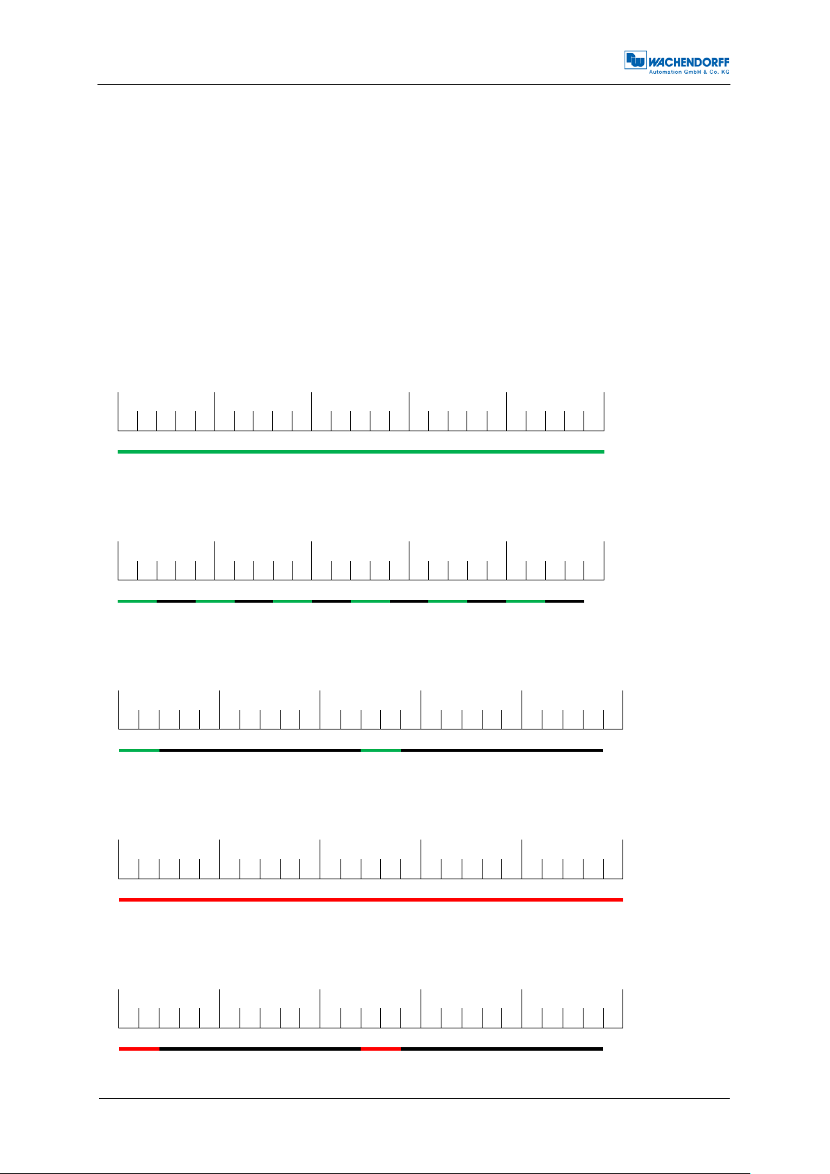
Green ON
Encoder is in
OPERATIONAL
state
0
500
1000
1500
2000
2500
Green blinking
Encoder is in
PREOPERATIONAL
state us
0
500
1000
1500
2000
2500
Green
single flash
Encoder is
in
STOPPED
state
0
500
1000
1500
2000
2500
Red ON
NOT ready /
BUS-OFF
0
500
1000
1500
2000
2500
Red single
flash
Warning,
occurrence
of error
frames
0
500
1000
1500
2000
2500
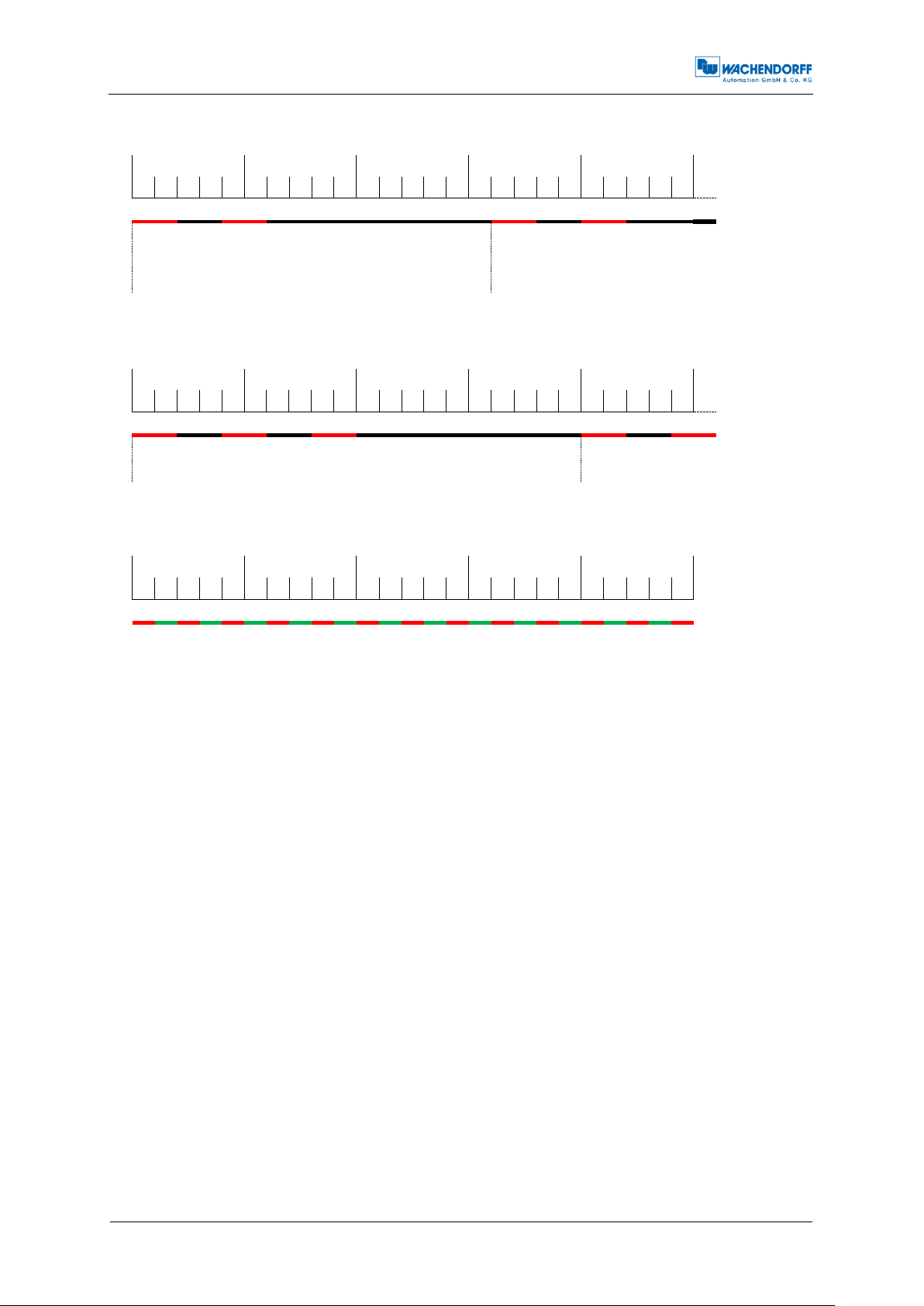
3.3 LED status indicator and signal codes
Definition of LED indication types:
= red LED indications = "Physical Layer" information
= green LED indications = "NMT-Status" information
= LED off
= continue like first cycle
LED-Indications [ms]:
Figure 3.2: LED indications 1
Technical Manual
WDGA with CANopen-Interface
3 - Device description
© Wachendorff Automation GmbH & Co. KG 7 Rev.1.24
Red double
flash
Error, a
guard event
or a heartbeat event
(heartbeat
consumer)
has
occurred
0
500
1000
1500
2000
2500
Cycle
Red tripple
flash
Encoder is
bus-passive
0
500
1000
1500
2000
2500
Cylce
red-green
flickering
BaudrateAutoDetection in
progress or
LSS config
modus
started
0
500
1000
1500
2000
2500
Figure 3.3: LED indications 2

Technical Manual
WDGA with CANopen-Interface
4 - Quick start
© Wachendorff Automation GmbH & Co. KG 8 Rev.1.24
The encoder indicates every status modification with its status-
LED. See chapter 3.3 "LED status indicator and signal codes".
080h
8
00h
00h
00h
00h
00h
00h
00h
00h
CAN-ID
DLC
Command
Byte0
Byte1
Byte2
Byte3
Byte4
Byte5
Byte6
4 Quick start
4.1 CAN network integration
The default node ID of Wachendorff Automation encoders (Object 2101h sub-Index:
00h) is 7Fh=127d.
For operating in a CAN-Network, the encoder’s baudrate has to be set. The common
ways to set the baudrate is via LSS (CiA DSP-305) or a SDO command.
Wachendorff Automation WDGA encoders have the capability to detect the baudrate
of the network automatically (object 2100h sub-Index: 00h value: 09h - Baudrate-autodetection). So usually the baudrate setup is not necessary. To detect the valid baudrate
the encoder stays passive and scans the communication at the bus. When the
baudrate is detected, the encoder is set to this rate, sends its boot-up message and
switches into pre-operational mode.
To prevent possible collisions in case double assigned node ID it is recommended to
use a 1:1 connection with a bus master for configuration (e.g. a laptop computer with
suitable hard- and software). Set the master on the intended baudrate and use SDO
or LSS services to configure the encoder.
4.2 SDO command to set the node ID
After connecting the encoder WDGA with the CAN bus respectively the master (e.g. a
laptop computer with suitable hard- and software) the LED starts "flickering red and
green" (see Figure 3.3 LED indications 2).
First send one or more SYNC messages, which the encoder can use to detect the
baudrate:
Table 4.1: SYNC-message
The encoder will detect and lock on the used baudrate. It will send its boot-up message
and the LED starts to blink green (see Figure 3.2).
Technical Manual
WDGA with CANopen-Interface
4 - Quick start
© Wachendorff Automation GmbH & Co. KG 9 Rev.1.24
600h+ID
8
2Fh
01h
21h
00h
Node-ID
00h
00h
00h
CAN-ID
DLC
Command
Object
L
Object
H
SubIndex
Byte0
Byte1
Byte2
Byte3
Node-ID (d)
Node-ID (h)
1
01h
2
02h
…
…
4
04h
…
…
127
7Fh
Changing the Node ID automatically adjusts the PDO and
EMCY COB IDs. After the first manual storage, they are frozen
at their current value and no longer automatically adjusted.
Performing the "Restore Defaults" command will re-enable
automatic adjustment.
To set the encoders node ID the object 2101h, Sub-Index 00h has to be accessed.
(Only possible in PRE-OPERATIONAL state!) Send a write-SDO-command with the
intended node ID (in hex):
Table 4.2: SDO-write command to set Node-ID
An example for a node ID might be:
Table 4.3: Node-ID in decimal and hexadecimal
The change of the node ID via SDO will be effective after a reset of the encoder (hard
reset or NMT reset). The new node ID is stored into the EEPROM immediately and
without a further command. The setting of the node ID via LSS is described in chapter
8.
4.3 Setting-up the encoder
Connect the encoder to the bus of application. Please mind the included mounting and
safety advice documents. You can find additional information to this in chapter 8
"Setting-up".
When the encoder is completely integrated into the application you can switch it into
OPERATIONAL mode by the "Start-All-Nodes-Command" (see chapter 7.1).

Technical Manual
WDGA with CANopen-Interface
4 - Quick start
© Wachendorff Automation GmbH & Co. KG
10
Rev.1.24
The encoder is now operational (LED shows green ON) and starts sending its data via
the several process data objects (PDO). The encoders default configuration plans that
the PDO1 is triggered once the position value changes.
The position value (object 6004h) is mapped in PDO1 and transmitted as an
Unsigned32. By default PDO2 transmits the same value but synchronously on the
reception of a SYNC message. Heartbeat is switched off and will not be transmitted by
default. The encoder is now configured and ready for basic applications.

Technical Manual
WDGA with CANopen-Interface
5 - General information about CAN
© Wachendorff Automation GmbH & Co. KG
11
Rev.1.24
5 General information about CAN
5.1 CAN physical and transport layer
CAN is a field bus. It operates with the CSMA/CA (Carrier Sense Multiple Access /
Collision Avoidance) method. It means that collisions during bus access are avoided
by a so called bitwise arbitration. The bits are coded NRZ-L (Non Return to Zero - Low).
A cyclic redundancy check (CRC) and other safety mechanisms provide a secure
transmission. For synchronisation a mechanism called "bit stuffing" is used. CAN is a
multi-master system, i.e. several equal bus nodes can be connected without a bus
master supervising the communication. In principle a CAN bus can be realized with
copper wire or in fibre optic cable.
The common CAN implementation with copper wire operates with differential signals,
transmitted via two wires: CAN
mode rejection ratio.
Data is transmitted with bits that can either be dominant or recessive. The dominant
(0) always overwrites the recessive (1).
HIGH
, CAN
. Therefore CAN has a good common
LOW
The topology of a CAN network is a line, which can be extended by stubs. The
maximum length of a stub is limited to 0,5m.
The network always has to be terminated on both ends with 120Ohms each (between
CAN
und CAN
HIGH
). Other locations or values are not allowed.
LOW
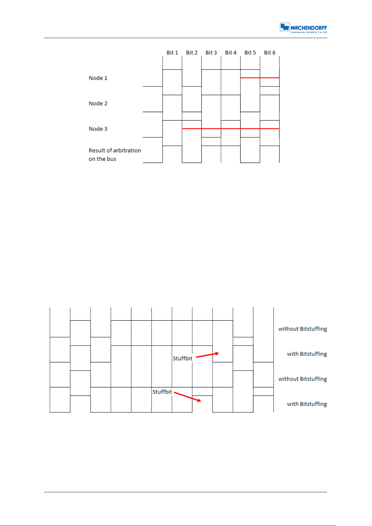
The arbitration mentioned before is used to control the bus access of the nodes by
prioritization of the CAN-Identifier of the different messages. Every node monitors the
bus. If more than on node wants access on the bus, the node with the highest priority
of the messages ID succeeds and the other nodes retreat until there is "silence" on
the bus (see Figure 5.1). Technically the first dominate bit of the ID send overwrites
the corresponding recessive bit of the other IDs. In case that more than one node
uses the same CAN-ID an error occurs only at a collision within the rest of the frame.
On principle a CAN-ID should only be used by a single node!
Technical Manual
WDGA with CANopen-Interface
5 - General information about CAN
© Wachendorff Automation GmbH & Co. KG
12
Rev.1.24
Figure 5.1: Example of the arbitration
Due to the arbitration there is a ranking of the messages. The message with the lowest
ID has the highest priority and therefore it has almost instant access on the bus. The
exception is that an ongoing transmission will not be interrupted. So time critical
messages should be assigned to the high priority CAN-IDs, but even then there is no
determination in the time of transmission (non-deterministic transmission).
For the arbitration all nodes have to be synchronised. Due to the lack of a separate
clock signal, the transmission of many identical bits in line would lead to the loss of
synchronisation. The so called bit-stuffing is used to prevent this case. After five equal
bits a complementary bit will be inserted into the transmission (the application will not
notice). So the nodes can keep up resynchronising on the bit flanks (see Figure 5.2).
Figure 5.2: Bitstuffing
Technical Manual
WDGA with CANopen-Interface
5 - General information about CAN
© Wachendorff Automation GmbH & Co. KG
13
Rev.1.24
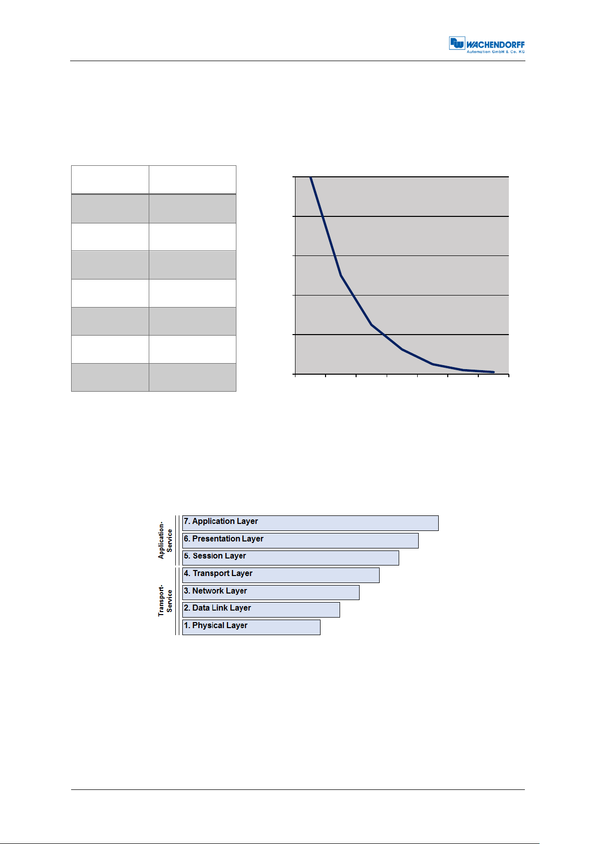
Baud rates
Cable length
10 kBit/s
6,7 km
20 kBit/s
3,3 km
50 kBit/s
1,3 km
125 kBit/s
530 m
250 kBit/s
270 m
500 kBit/s
130 m
1 MBit/s
<40 m
0
200
400
600
800
1000
40 150 270 530 1300 3300 6700
Baudrate [kbits/s]
Cable length [m]
A CAN network can operate with baud rates up to 1 Mbit/s. Due to the necessary
synchronisation of the nodes, the maximum delay caused by the length of the cable
has to be limited. The limitation corresponds with the baudrate. There is a common
recommendation of the maximum cable length at several baud rates.
Table 5.1: CAN baud rates und recommended cable length limits
5.2 CANopen
CANopen is a specified higher protocol (layer 7 protocol) (Figure 5.3).
Figure 5.3: ISO-OSI-Modell
With CANopen it is possible to transfer larger amounts of data, emergency telegrams
and process data. CANopen describes how the communication is performed. That
means that parameters to configure a device are transmitted in a defined form (profile).
A CANopen profile defines objects representing the different functions of a device.
These objects form a table called object dictionary.

Technical Manual
WDGA with CANopen-Interface
5 - General information about CAN
© Wachendorff Automation GmbH & Co. KG
14
Rev.1.24
Specification
Description
CiA 301
Application Layer and Communication Profile
CiA 303
Cabling/pin assignment, Representation of units, Indicator specification
CiA 305
Configuration of baudrate und node ID via LSS
CiA 306
Electronic Data Sheet
CiA 406
Device-/Application-profile
The communication profile defines the basic services and parameters of a CANopen
device (e.g. service data objects SDOs, process data objects PDOs, used CAN-IDs,
etc.).
The device profile defines the specific functions of a device family (e.g. encoders, i/o
devices, ...). For encoders the device profile is the encoder profile CiA 406.
5.3 Specifications and profiles
5.3.1 Overview
The CANopen specifications were defined by the CiA in Draft Standards. Concerning
the WDGA encoders the following specifications are from special importance:
Table 5.2: Draft Standards
5.3.2 Mechanisms of communication
There are several different CANopen communication services:
SDO Service Data Object
Use: for access to the object dictionary. There is one single SDO-channel.
Two identifiers are assigned to the SDO channel, one for each direction of
transmission.
For SDO the 8 byte CAN frame is divided into 1 byte command, a multiplexor of 2 byte
index and 1 byte sub index of the object dictionary, and 4 byte of payload. For bigger
payloads either segmented or block transfer is used.
A SDO transmission will always be acknowledged by the receiver. In case of a failure
an "abort message" is send. The internal delay time of the WDGA encoders is 1
millisecond maximum.
PDO Process Data Object
Use: for transmission of process data. The WDGA encoders provide up to four PDOs.
A PDO uses the full length of the data area of a CAN frame (8 bytes) for the process
data without additional overhead.
 Loading...