

TIMER TI484801
TIMER
Wachendorff Prozesstechnik GmbH & Co. KG
e-mail: RSS@wachendorff.de
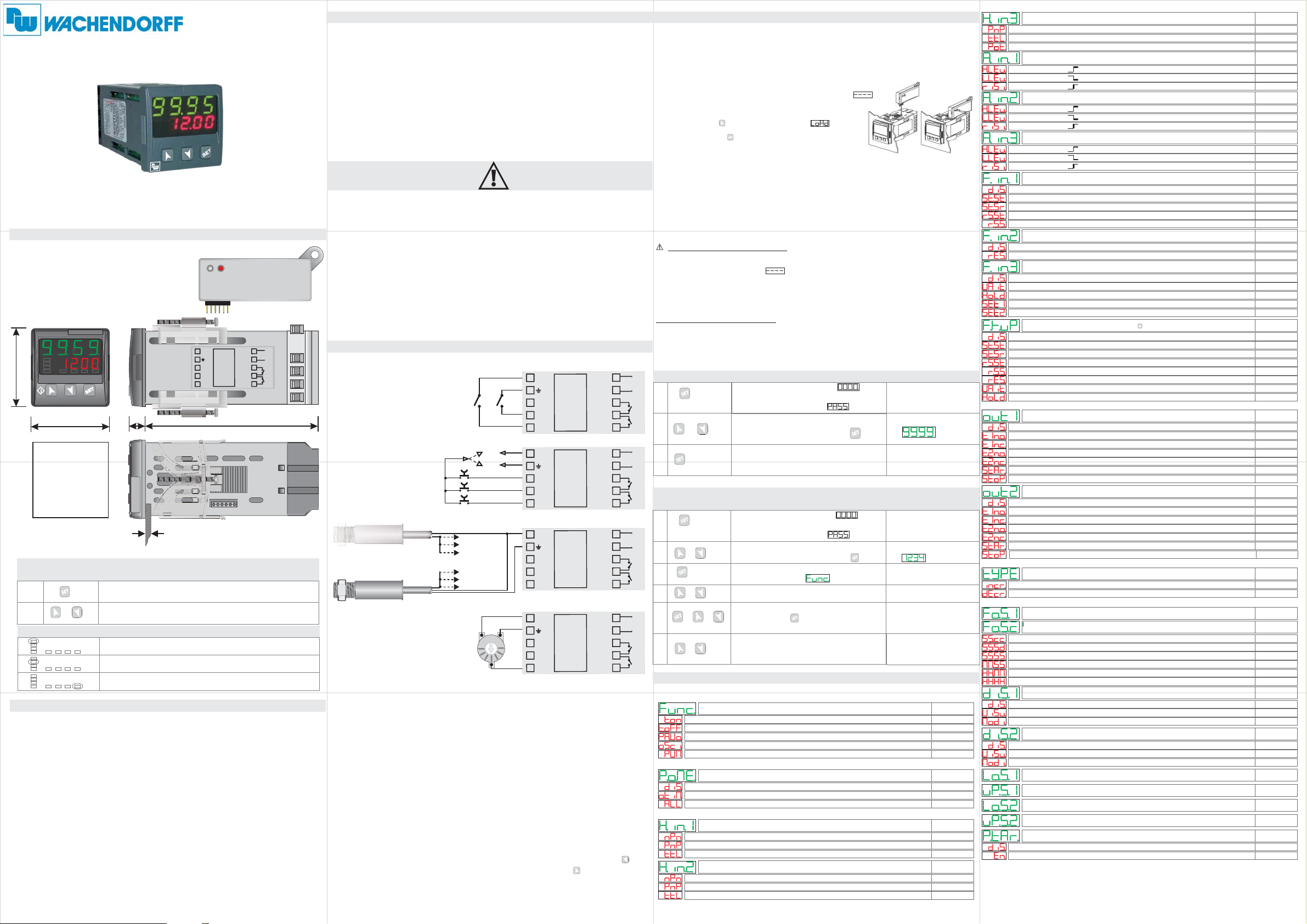
SIZE AND INSTALLATIONSIZE AND INSTALLATION
memory card (optional)
C1C1
C2C2
A1
MAN TUN REM
A2
48 mm
A3
48 mm
Front panel
cut out
46x46mm
MEMORYC.241MEMORYC.241
SETPOINT MODIFICATIONSETPOINT MODIFICATION
PRESS
1
2
TECHNICAL DATATECHNICAL DATA
or
LED
C1C1
C2C2
A1
MAN TUN REM
A2
A3
C1C1
C2C2
A1
MAN TUN REM
A2
A3
C1C1
C2C2
A1
MAN TUN REM
A2
A3
Operating
temperature
Sealing
Material
Digital Inputs
Outputs
OUT 24V
Back-UP
Power Supply
MEANING
Report the activation of Q1
Report the activation of Q2
Report serial transmission by the TI484801
Operating temperature 0-40°C, humidity
35..95uR%
IP65 (with gasket) on front panel,
IP20 box and terminal blocks
PC ABS UL94V0 self-extinguishing
3PNP/NPN configurable as analogue for
potentiometers.(max 28 Vdc in PNP mode)
2 relays 8A resistive charge
30mA(24Vac),40mA(24 Vdc),60mA (110...230Vac)
.
Rechargeable battery, approx. 60days autonomy
24...230Vac/Vdc +/-15% 50/60Hz / 2W
MANUAL
MANUAL
TI484801
www.wp-direkt.de
Version 2.0
Insertion of
2to mm
suggested thickness
DISPLAY
Visualizes SETPOINT 1 / 2
Modifies selecter SET
1 6
OUT
5
50mA
4
I1
3
I2
2
I3
1
6
CN1
4V
2
Service ab.
dem
die Versorgung vor
Gefahr eines elektr.
ACHTUNG
Schlags. Schalten Sie
106 mm10
16
Memory Card
8A230V
Resistiv
1/2HP
8A230V
Resistiv
1/2HP
INTRODUCTION
Thanks for choosing a Wachendorff device.
The timer TI484801 can be set in 5 different modes; Timer-ON, TimerOFF, Pause-Work, Oscillator, PWM (time-proportioned output), all
options with independent settings of ON-OFF time.
3 universal digital inputs are availables (NPN/PNP/Potential free
contact) for external commands like Start, Stop and Reset; one input is
also analogue in order to allow the modification of working times by an
external potentiometer.
5 different time bases (hundredths, tenths, seconds, minutes, hours).
Counting can be incremental or decremental.
Read carefully the safety guidelines and programming instructions
contained in this manual before using/connecting the device.
Disconnect power supply before proceeding to hardware settings or
electrical wirings.
Only qualified personnel should be allowed to use the device and/or
service it and in accordance to technical data and environmental
conditions listed in this manual.
Do not dispose electric tools together with household waste materials in
observance of European Directive 2002/96/CE
5
10
Versorg.
24...230V
AC/DC
9
8
Q1
7
Q2
6
WIRING DIAGRAMWIRING DIAGRAM
4
3
2
1
PNP
PNP
NPN
Proximity
Sensor PNP
2 wires
Proximity
Sensor PNP
3 wires
OUTPUT
I1
I2
I3
I1
I2
I3
NPN
+
-
5
OUT 24V
4
I1
3
I2
2
I3
1
5
OUT 24V
4
I1
3
I2
2
I3
1
5
OUT 24V
4
I1
3
I2
2
I3
1
5
OUT 24V
4
I1
3
I2
2
I3
1
servicing
supply before
Disconnect power
CAUTION
Risk of Electric Shock
servicing
supply before
Disconnect power
CAUTION
Risk of Electric Shock
servicing
supply before
Disconnect power
CAUTION
Risk of Electric Shock
servicing
supply before
Disconnect power
CAUTION
Risk of Electric Shock
POTENTIOMETER 0 to 5/10 Kohm
Accuracy 1.000 points
Potentiometer:
To modify Set1 or Set2 by external potentiometer follow the steps below:
1-
use potentiometers 0 to 5/10kohm
2-
connect cursor to pin I3; a wrong connection may damage the potentiometer and
lead to lock of the device.
3-
accuracy on input is max 1000 points, therefore set the parameters "Upper limit"
and "Lower limit" with a max difference of 1000 units.
(Ex.: LoS1 to 50,0 and uPS1 to 150,0 to modify time value related to Set1 between
50 and 150 seconds with steps of one tenth). Greater differences would make
unstable the less significant digit.
4-
To calibrate the scale of potentiometer enter the configuration mode and select:
Hin.3 as Pot
Fin.3 as Set1 or Set2
P.tAr as Enable
Exit configuration mode and place potentiometer at minimum leveland press key,
then place potentiometer at max level and press premere key: the device
automatically exit the calibration procedure.
N.B.:Aswitch-off ofthedevicewouldinterruptthecalibration.
8A 230V
Resistiv
1/2HP
8A 230V
Resistiv
1/2HP
8A 230V
Resistiv
1/2HP
8A 230V
Resistiv
1/2HP
8A 230V
Resistiv
1/2HP
8A 230V
Resistiv
1/2HP
8A 230V
Resistiv
1/2HP
8A 230V
Resistiv
1/2HP
10
9
8
7
6
10
9
8
7
6
10
9
8
7
6
10
9
8
7
6
SUPPLY
24...230V
AC/DC
Q1
Q2
SUPPLY
24...230V
AC/DC
Q1
Q2
SUPPLY
24...230V
AC/DC
Q1
Q2
SUPPLY
24...230V
AC/DC
Q1
Q2
MEMORY CARD (optional)MEMORY CARD (optional)
Parameters and setpoint values can be copied from one device to another using
the Memory card
.
Attention: Pls. perform an update of the memory card first.
There are two methods:
With the device connected to the power supply
>
insert the memory card .
when the controller is off
On activation display 1 shows and display 2 shows
(Only if the values stored on Mmeory Card are correct).
By pressing the key display 2 shows
Confirm using the key .
The device loads the new data and starts again
With the controller disconnected from the power supply:
>
.
The memory card is equipped with an internal battery with a life of about 1000 uses.
Insert the memory card and press the programming button.
When writing the parameters, the LED turns red and on completing the procedure
it changes to green. It is possible to repeat the procedure.
UPDATING MEMORY CARD.
update
To the memory card values, follow the procedure described in the first
method, setting display 2 to so as not to load the parameters on controller.
Enter configuration and .
change at least one parameter
Exit configuration. Changes are saved automatically.
LOADING DEFAULT VALUES
This procedure restores the factory settings of the instrument.
LOADING DEFAULT VALUESLOADING DEFAULT VALUES
1
2
3
PRESS
SET for
3 seconds
or
to confirm
pass to the next one pressing
DISPLAY DO
On display 1 appears
with 1st digit blinking, while
display 2 shows
Modify blinking digit and
Device loads
default values
Enter Password
Switch the device off
and restart it
CONFIGURATION PARAMETER MODIFICATIONCONFIGURATION PARAMETER MODIFICATION
1
2
3
4
5
6
PRESS
SET for
3 seconds
or
to confirm
or
+ or
+
pass to the next one pressing
Display shows first parameter of
configuration table
Increase or decrease visualized value
pressing and an arrow key
End configuration, controller exits
DISPLAY DO
On display 1 appears
with 1st digit blinking, while
display 2 shows
Modify blinking digit and
Scroll parameters
from configuration
Enter Password
Enter the new data
that will be
saved when releasing keys
LIST OF PARAMETERSLIST OF PARAMETERS
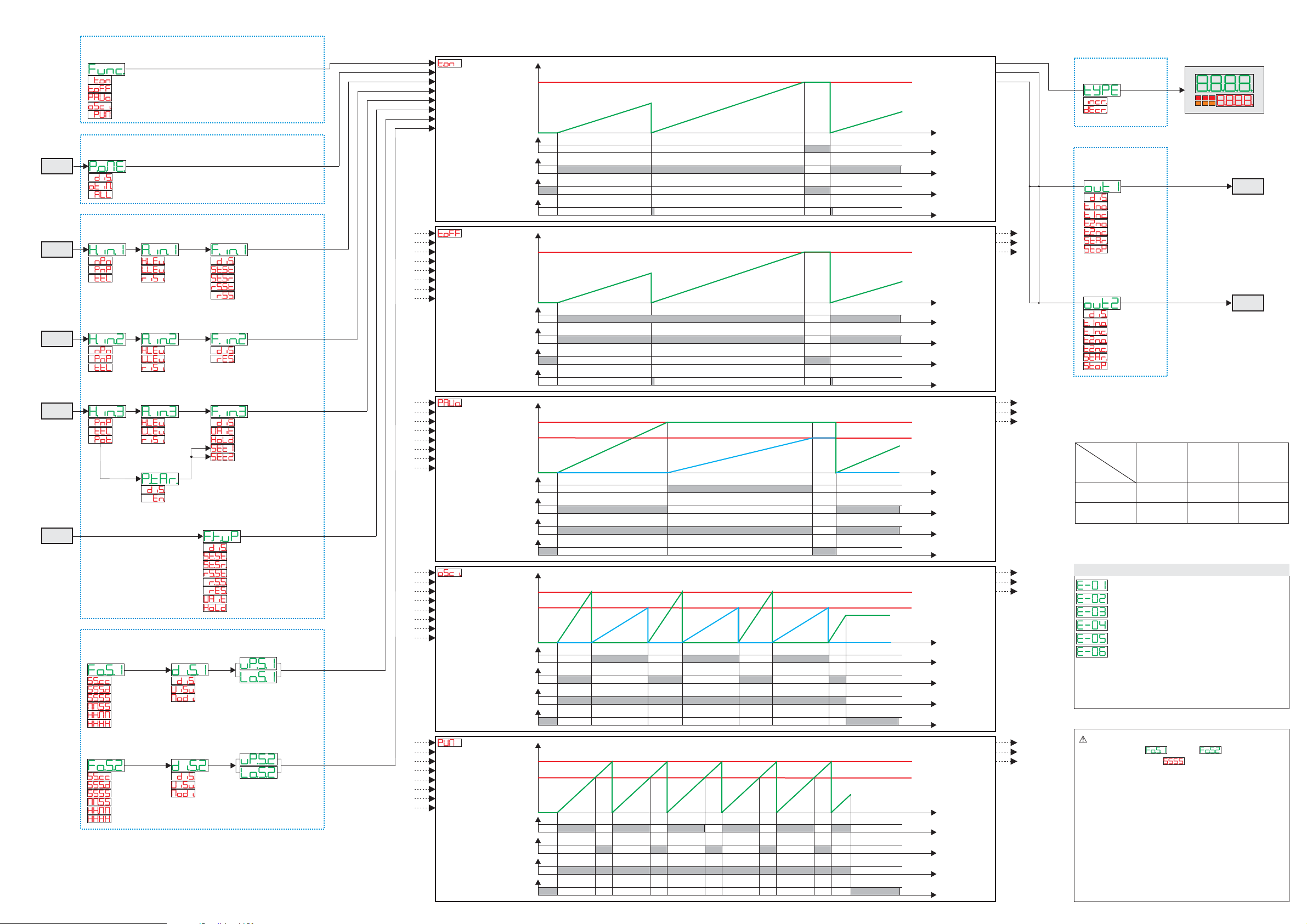
FUNCTION CONFIGURATION
P-01 Timer Function
Timer On
Timer Off
Pause/Work
Oscillator
PWM
BACKUP MEMORY CONFIGURATION
P-02 Power-off Memory
Disable
Only Timer
Timer / State
INPUT CONFIGURATION
P-03 Hardware Input 1
NPN
PNP
TTL
P-04 Hardware Input 2
NPN
PNP
TTL
Timer functions
Activates output at count end
Deactivates output at count end
T1 and T2 start in sequency
T1 and T2 start in sequency repeatedly
Percentage output activation on fixed time base
Power-off memory
Disabled
Only timer value in memory
Timer value and START/STOP status in memory
Input 1 configuration
NPN
PNP
TTL
Input 2 configuration
NPN
PNP
TTL
Default
Default
Default
Default
P-05 Hardware Input 3
PNP
TTL
Potent.
P-06 Active State Input 1
High Level
Low Level
Rising edge
P-07 Active State Input 2
High Level
Low Level
Rising edge
P-08 Active State Input 3
High Level
Low Level
Rising edge
P-09 Function Input 1
Disable
Start / Stop
Start / Stop-Reset
Reset-Start / Stop
Reset / Start / Stop
P-10 Function Input 2
Disable
Reset
P-11 Function Input 3
Disable
Wait
Hold
Potent. To SET1
Potent. To SET2
P-12 Function Key UP
Disable
Start / Stop
Start / Stop-Reset
Reset-Start / Stop
Reset / Start / Stop
Reset
Wait
Hold
OUTPUT CONFIGURATION
P-13 Output Q1 Setup
Disable
Out Timer 1 n.o.
Out Timer 1 n.c.
Out Timer 2 n.o.
Out Timer 2 n.c.
Start
Stop
P-14 Output Q2 Setup
Disable
Out Timer 1 n.o.
Out Timer 1 n.c.
Out Timer 2 n.o.
Out Timer 2 n.c.
Start
Stop
DISPLAY CONFIGURATION
P-15 Type of Timer
Incremental
Decremental
SETPOINT CONFIGURATION
P-16 Format Set 1
P-17 Format Set 2
Second.Cent
Second.Decimal
Second
Minute.Second
Hour.Minute
Hour
P-18 Display Set 1
Disable
Visualized
Modifiable
P-19 Display Set 2
Disable
Visualized
Modifiable
P-20 Lower limit Set 1
P-21 Upper limit Set 1
P-22 Lower limit Set 2
P-23 Upper limit Set 2
P-24 Potent. tarature
Disable
Enable
Input 3 configuration
PNP
TTL
Potentiometer
Input 1 activation
High level
Low level
Transitory in rising
Input 2 activation
High level
Low level
Transitory in rising
Input 3 activation
High level
Low level
Transitory in rising
Input 1 function
Disabled
Start / Stop
Start / Stop-Reset
Reset-Start / Stop
Reset / Start / Stop
Input 2 function
Disabled
Reset
Input 3 function
Disabled
Wait (count lock)
Hold (locks display but count continues)
Modify SET1 by potentiometer
Modify SET2 by potentiometer
Function of
Disabled
Start / Stop
Start / Stop-Reset
Reset-Start / Stop
Reset / Start / Stop
Reset
Wait (count lock)
locks display but count continuels
Hold ( )
Output Q1 selection
Disabled
Timer output 1 n.o.
Timer output 1 n.c.
Timer output 2 n.o.
Timer output 2 n.c.
Start
Stop
Output Q2 selection
Disabled
Timer output 1 n.o.
Timer output 1 n.c.
Timer output 2 n.o.
Timer output 2 n.c.
Start
Stop
Count mode
Incremental
Decremental
Count format
Count format
Seconds, Cents
Seconds, Tenths
Seconds
Minutes, Seconds
Hour, Minutes
Hour
Set 1 visualization
Disabled
Visualized
Visualized and modifiable
Set 2 visualization
Disabled
Visualized
Visualized and modifiable
Set 1 lower limit
Set 1 upper limit
Set 2 lower limit
Set 2 upper limit
Potentiometer calibration procedure
Disabled
Enabled
Default
Default
Default
Default
Default
Default
Default
Default
Default
Default
Default
Default
Default
Default
0.0
99.9
0.0
99.9
Default
FUNCTION CONFIGURATION
P-01
Timer
Function
Timer On (Nota 1)
Timer Off (Nota 1)
Pause/Work (Nota 1)
Oscillator
PWM
BACKUP MEMORY CONFIGURATION
P-02
Power-off
POWER-ON
RESET
Memory
Disable
Only Timer
Timer / State
INPUT CONFIGURATION
P-03
Hardware
Input 1
P-06
Active State
Input 1
P-09
Function
Input 1
I1
P-04
Hardware
Input 2
NPN
PNP
TTL
High Level
Low Level
Rising edge
P-07
Active State
Input 2
Disable
Start / Stop (Nota 2)
Start / Stop-Reset
Reset-Start / Stop
Reset / Start / Stop
P-10
Function
Input 2
I2
High Level
Low Level
Rising edge
P-08
Active State
Input 3
P-11
Function
Input 3
Disable
Reset
P-05
Hardware
Input 3
NPN
PNP
TTL
I3
PNP
TTL
Potent.
Key UP
SETPOINT CONFIGURATION
P-16
Format
Set 1
Second.Cent
Second.Decimal
Second
Minute.Second
Hour.Minute
Hour
P-17
Format
Set 2
Second.Cent
Second.Decimal
Second
Minute.Second
Hour.Minute
Hour
Note 1: In this timer functioning, if
at count end (reaching setpoint), timer will switch automatically to STOP.
Note 2: This function not reset timer value, and so it requires an input for the reset.
Nota 3: This function reset timer at STOP.
Note 4: This function reset timer at START.
Note 5: This function è attiva solo se P-06 Active State Input 1 = Rising Edge
High Level
Low Level
Rising edge
P-24
Potentiometer
calibration
Disable
Enable
P-18
Display
Set 1
P-19
Display
Set 2
Disable
Visualized
Modifiable
Disable
Visualized
Modifiable
Disable
Wait
Hold
Potent. To SET1
Potent. To SET2
P-12
Function
Key UP
Disable
Start / Stop (Nota 2)
Start / Stop-Reset (Note 3)
Reset-Start / Stop (Note 4)
Reset / Start / Stop
Reset
Wait
Hold
P-21
Upper limit
Set 1
P-20
Lower limit
Set 1
P-23
Upper limit
Set 2
P-22
Lower limit
Set 2
P-06 Active State Input 1 = Rising Edge or P-09 Function Input 1 = Disable,
(Note 3)
(Note 4)
(Note 5)
Timer On
Stop/Reset
Start/Stop/Reset
Reset
Wait/Hold/Set1-2
Start/Stop/Reset/Wait/Hold
Set1
Set2
Out Timer 1
Reset
Timer Off
Stop/Reset
Start/Stop/Reset
Reset
Wait/Hold/Set1-2
Start/Stop/Reset/Wait/Hold
Set1
Set2
Out Timer 1
Reset
Pause / Work
Stop/Reset
Start/Stop/Reset
Reset
Wait/Hold/Set1-2
Start/Stop/Reset/Wait/Hold
Set1
Set2
Out Timer 1
Out Timer 2
Oscillator
Stop/Reset
Start/Stop/Reset
Reset
Wait/Hold/Set1-2
Start/Stop/Reset/Wait/Hold
Set1
Set2
Out Timer 1
Out Timer 2
PWM
Stop/Reset
Start/Stop/Reset
Reset
Wait/Hold/Set1-2
Start/Stop/Reset/Wait/Hold
Set1
Set2
Out Timer 1
Out Timer 2
Start
Stop
Start
Stop
Start
Stop
Start
Stop
Start
Stop
Set
Set
Set
Set
Set
TI484801 “TIMER”
DISPLAY CONFIGURATION
Timer value
SET1
Out Timer 1
Out Timer 2
TIMER 1TIMER 1
1
0
1
0
1
0
1
0
Time
Timer value
SET1
Out Timer 1
Out Timer 2
TIMER 1TIMER 1
1
0
1
0
1
0
1
0
Time
Timer value
TIMER 1TIMER 1
SET1
Out Timer 1
Out Timer 2
SET2
TIMER 2TIMER 2
1
0
1
0
1
0
1
0
Time
Timer value
TIMER 1TIMER 1
SET1
Out Timer 1
Out Timer 2
SET2
TIMER 2TIMER 2
1
0
1
0
1
0
1
0
Time
Timer value
TIMER 1
TIMER 1
SET2 (Period)SET2 (Period)
Out Timer 1
Out Timer 2
SET1(% duty-Cycle)SET1(% duty-Cycle)
1
0
1
0
1
0
1
0
Time
P-15
Type
of Timer
Incremental
Decremental
123
OUTPUT CONFIGURATION
P-13
Output Q1
Setup
Q1
Disable
Out Timer 1 n.o.
Out Timer 1 n.c.
Out Timer 2 n.o.
Out Timer 2 n.c.
Start
Stop
P-14
Output Q2
Setup
Q2
Disable
Out Timer 1 n.o.
Out Timer 1 n.c.
Out Timer 2 n.o.
Out Timer 2 n.c.
Start
Stop
LOGIC
LEVEL
H
L
INPUT
TYPE
NPN
INPUT
< 4,7 v
> 5,7 v
TABLE of ERROR MESSAGESTABLE of ERROR MESSAGES
ERROR WRITING EEPROM Memory (Note 1)
ERROR READING EEPROM Memory (Note 1)
Incorrect parameters (Note 1)
Incorrect calibration data (Note 1)
Incorrect status data (Note 1)
Incorrect BACKUP registers (Note 2)
Note 1:
Switch the device off and restart it; if error is still notified, contact
technical service
Note 2:
Discharged battery: keep the device connected to power supply in
order to recharge the battery.
In PWM mode, the only option available on
parameters 16 and 17 for format of
SET1 and SET2 is (seconds).
Low and upper limits for SET1 (related to
percentage of work orDuty Cycle) are allowed in
the range 0 ... 100 (%).
PNP
INPUT
>5,7 v (I1, I2)
>12,4 v (I3)
< 4,7 v (I1, I2)
< 10,2 v (I3)
TTL
INPUT
>2,5 v
< 2,0 v
 Loading...