

Wachendorff TI327401 User guide
MANUAL
MANUAL
TIMER TI327401
TIMER
Wachendorff Prozesstechnik GmbH & Co. KG www.wp-direkt.de
e-mail: RSS@wachendorff.de
TI327401
Version 2.0
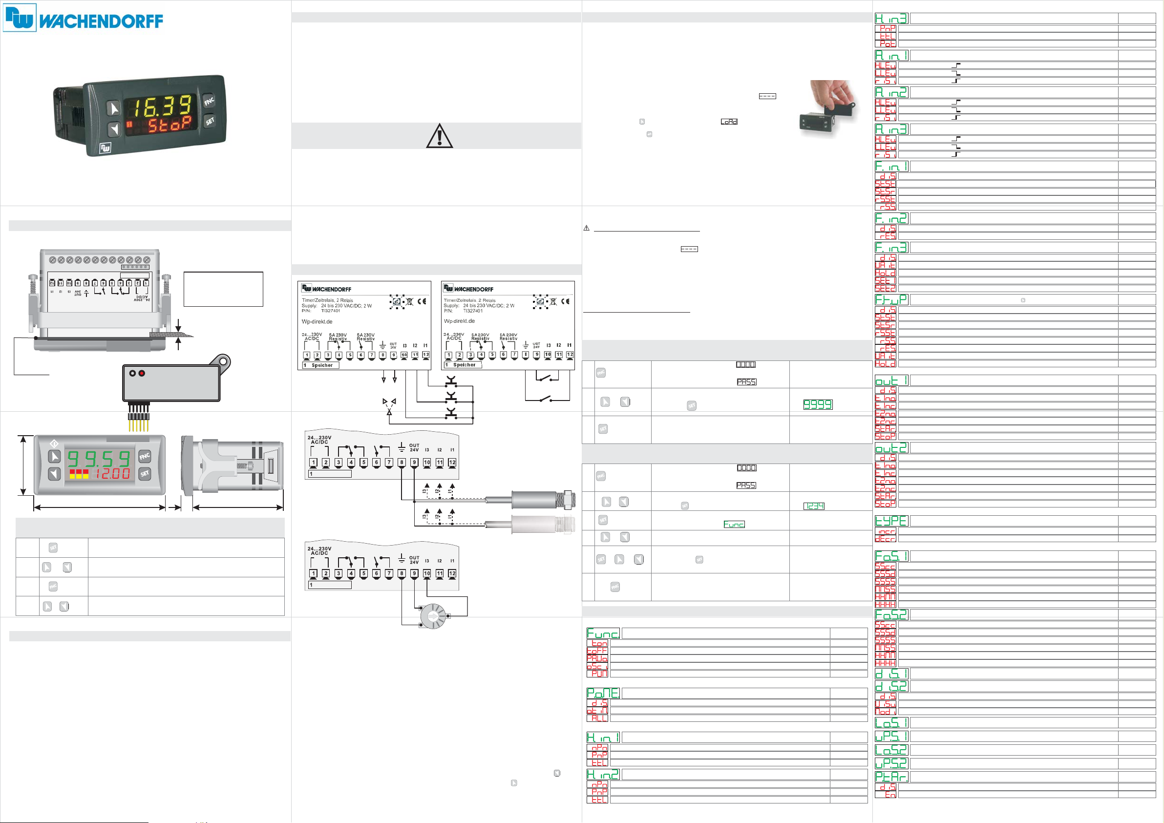
DIMENSION and INSTALLATIONDIMENSION and INSTALLATION
Q1
Q1
Q2
Q2
1/2HP
1/2HP
1/2HP
1/2HP
Resistive
Resistive
Resistive
Resistive
5A230V
5A230V
5A230V
5A230V
Gasket
PIXSYS
1 6
CN1
Memory card (optional)
with battery (SFUR0KIT)
35 mm
123
77 mm
7
MODIFY SETPOINTMODIFY SETPOINT
1
2
2a
3a
PRESS
OR
O
Modify the flashing digit of the selected setpoint
EFFECT
Display SETPOINT 1 / 2
Modify selected SETPOINT
Select the chosen digit
TECHNICAL DATATECHNICAL DATA
Operating
temperature
Sealing
Material
Outputs
OUT 24V
Back-UP
Programming
Software
Power Supply
Operating temperature 0-40°C, humidity 35..95uR%
Front panel IP65 (with optional gasket) ,
Box IP30, Terminal blocks IP20
PC ABS UL94V0 self-extinguishing
Digital
3PNP/NPN configurable as analogue for potentiometers.
Inputs
(max 28 Vdc in PNP mode)
2 relays 5A resistive charge
30mA(24Vac),40mA(24 Vdc),60mA (110...230Vac)
.
Rechargeable battery, approx. 7days autonomy
Labsoftview 2.6 or later
24...230Vac/Vdc +/-15% 50/60Hz / 2W
Front panel
cut out
28.5 x 70.5 mm
2to mm
8
suggested thickness
53 mm
INTRODUCTION
Thanks for choosing a Wachendorff device.
Timer TI327401 can be set in 5 different modes: Timer-ON, Timer-OFF,
Pause-Work, Oscillator, PWM (time-proportioned output), all options
with independent setting of ON-OFF time.
3 digital inputs are available (NPN/PNP) for external commands like
Start, Stop, Reset; one input is also analogic in order to allow the
modification of working times by external potentiometer.
5 different time bases (hundredths, tenths, seconds, minutes, hours).
Counting can be incremental or decremental.
MEMORY CARD (optional)MEMORY CARD (optional)
Parameters and setpoint values can be copied from one device to
another using the Memory card
memory card.
There are two methods:
>
With the device connected to the power supply
insert the memory card .
On activation display 1 shows and display 2 shows
(Only if the values stored on Mmeory Card are correct).
By pressing the key display 2 shows
.A
ttention: pls. Perform first an update of the
when the controller is off
Confirm using the key .
The device loads the new data and starts again
Read carefully the safety guidelines and programming instructions
contained in this manual before using/connecting the device.
Disconnect power supply before proceeding to hardware settings or
electrical wirings.
Only qualified personnel should be allowed to use the device and/or
service it and in accordance to technical data and environmental
conditions listed in this manual.
Do not dispose electric tools together with household waste materials in
observance of European Directive 2002/96/CE
WIRING DIAGRAMWIRING DIAGRAM
>
With the controller disconnected from the power supply:
The memory card is equipped with an internal battery with a life of about 1.000
uses.
Insert the memory card and press the programming button.
When writing the parameters, the LED turns red and on completing the procedure
it changes to green. It is possible to repeat the procedure.
UPDATING MEMORY CARD.
update
To the memory card values, follow the procedure described in the first
method, setting display 2 to so as not to load the parameters on controller.
Enter configuration and .
change at least one parameter
Exit configuration. Changes are saved automatically.
LOADING DEFAULT VALUES
This procedure restores the factory settings of the instrument.
LOADING DEFAULT SETTINGSLOADING DEFAULT SETTINGS
EFFECT
Display 1shows
and 1st digit flashes,
Display 2 shows
Modify the flashing digit,
(factory settings)
NPN
PNP
PNP
NPN
1
2
3
PRESS
for 3 seconds
Or
to confirm
press to reach the next digit
The device loads default values
MODIFY PARAMETERS
Speicher
Speicher
PRESS
1
2
3
4
5
6
for 3 seconds
Or
to confirm
Or
+ Or
press to reach the following digit
Display shows first parameter
of configuration table
Increade or decrease value on display
by pressing and one of the arrow keys
the device exits programming mode.
+-
OUT
OUT
Proximity
sensor PNP
3 wires
Proximity
sensor PNP
2 wires
POTENTIOMETER 0 to 5/10 Kohm
Accuracy 1.000 points
EFFECT OPERATION
Display 1 shows
and 1st digit flashes,
display 2 shows
Modify flashing digit,
Scroll the parameters
at same time
End of configuration,
LIST of PARAMETERSLIST of PARAMETERS
FUNCTION CONFIGURATION
Potentiometer:
To modify Set1or Set2 byexternal potentiometer followthe steps below:
1 usepotentiometers 0 to5/ 10kohm
-
2 connect cursor to pin I3; a wrong connection ma damage the
-y
potentiometer and leadto lock ofth device.
3 accuracy on input is max 1000 points, therefore set the parameters "Upper
-
limit" and "Lowerlimit with a max difference of 1000 units.
"
e
BACKUP MEMORY CONFIGURATION
(Ex.: LoS1 to 50,0 and uPS1 to 150,0 to modify time value related to Set1 between
50 and 150 seconds with steps of one tenth). Greater differences would make
unstable the lesssignificant digit.
4 To calibrate the scale of potentiometer enter t e configuration mode and
-h
select:
INPUT CONFIGURATION
Hin.3 as Pot
Fin.3 as Set1or Set2
P.tAr as Enable
Exit configuration mode and place potentiometer at minimum level and press key,
then place potentiometer at max level and press premere key: the device
automatically exit thecalibration procedure.
N.B.:Aswitch-off of thedevice would interruptthe calibration.
P-01 Timer Function
Timer On
Timer Off
Pause/Work
Oscillator
PWM
P-02 Power-off Memory
Disable
Only Timer
Timer / State
P-03 Hardware Input 1
NPN
PNP
TTL
P-04 Hardware Input 2
NPN
PNP
TTL
Timer operating modes
Activate output at elapsing of counting
Deactivate output at elapsing of counting
T1 and T2 start in sequence
T1 and T2 start in sequence and cycling
Activate a percentage of output on a fixed time base
Memory after switch-off
Disabled
Memory stores only value of Timer
Configuration Input 1
NPN
PNP
TTL
Configuration Input 2
NPN
PNP
TTL
P-05 Hardware Input 3
PNP
TTL
Potent.
P-06 Active State Input 1
High Level
Low Level
Rising edge
P-07 Active State Input 2
High Level
Low Level
Rising edge
P-08 Active State Input 3
High Level
.
OPERATION
Enter password
Switch-off and restart
the device
Enter password
Enter new data
which will be stored
releasing the keys
Default
Default
START/STOP statusMemory stores value of Timer and
Default
Default
Low Level
Rising edge
P-09 Function Input 1
Disable
Start / Stop
Start / Stop-Reset
Reset-Start / Stop
Reset / Start / Stop
P-10 Function Input 2
Disable
Reset
P-11 Function Input 3
Disable
Wait
Hold
Potent. To SET1
Potent. To SET2
P-12 Function Key UP
Disable
Start / Stop
Start / Stop-Reset
Reset-Start / Stop
Reset / Start / Stop
Reset
Wait
Hold
OUTPUT CONFIGURATION
DISPLAY CONFIGURATION
SETPOINT CONFIGURATION
P-13 Output Q1 Setup
Disable
Out Timer 1 n.o.
Out Timer 1 n.c.
Out Timer 2 n.o.
Out Timer 2 n.c.
Start
Stop
P-14 Output Q2 Setup
Disable
Out Timer 1 n.o.
Out Timer 1 n.c.
Out Timer 2 n.o.
Out Timer 2 n.c.
Start
Stop
P-15 Type of Timer
Incremental
Decremental
P-16 Format Set 1
Second.Cent
Second.Decimal
Second
Minute.Second
Hour.Minute
Hour
P-17 Format Set 2
Second.Cent
Second.Decimal
Second
Minute.Second
Hour.Minute
Hour
P-18 Display Set 1
P-19 Display Set 2
Disable
Visualized
Modifiable
P-20 Lower limit Set 1
P-21 Upper limit Set 1
P-22 Lower limit Set 2
P-23 Upper limit Set 2
P-24 Potent. tarature
Disable
Enable
Configuration input 3
PNP
TTL
Potentiometer
Activate Input 1
High level
Low level
Rising edge
Activate Input 2
High level
Low level
Rising edge
Activate Input 3
High level
Low level
Rising edge
Function of Input 1
Disabled
Start / Stop
Start / Stop-Reset
Reset-Start / Stop
Reset / Start / Stop
Function Input 2
Disabled
Reset
Function Input 3
Disabled
Wait
(stop the counting)
(Hold value on display but counting goes on)
Hold
Modify SET1 by potentiometer
Modify SET2 by potentiometer
Function of key
Disabled
Start / Stop
Start / Stop-Reset
Reset-Start / Stop
Reset / Start / Stop
Reset
Wait (stop the counting)
(hold value on display but counting goes on)
Hold
Setting of output Q1
Disabled
Output Timer 1 N.O.
Timer 1 N.C.
Output
Timer 2 N.O.
Output
Timer 2 N.C.
Output
Start
Stop
Setting of output Q2
Disabled
Output Timer 1 N.O.
Output Timer 1 N.C.
Output Timer 2 N.O.
Output Timer 2 N.C.
Start
Stop
Counting mode
Incremental
Decremental
Format of counting
Seconds, Hundredths
Seconds, Tenths
Seconds
Minutes, Seconds
Hours, Minutes
Hours
Format of counting
Seconds, Hundredths
Seconds, Tenths
Seconds
Minutes, Seconds
Hours, Minutes
Hours
Visualization of Set 1
Visualization of Set 2
Disabled
Visualized
Visualized and modifiable
Low limit Set 1
Upper limit Set 1
Low limit Set 2
Upper limit Set 2
Calibration of potentiometer
Disabledd
Enabled
Default
Default
Default
Default
Default
Default
Default
Default
Default
Default
Default
Default
Default
Default
0.0
99.9
0.0
99.9
Default
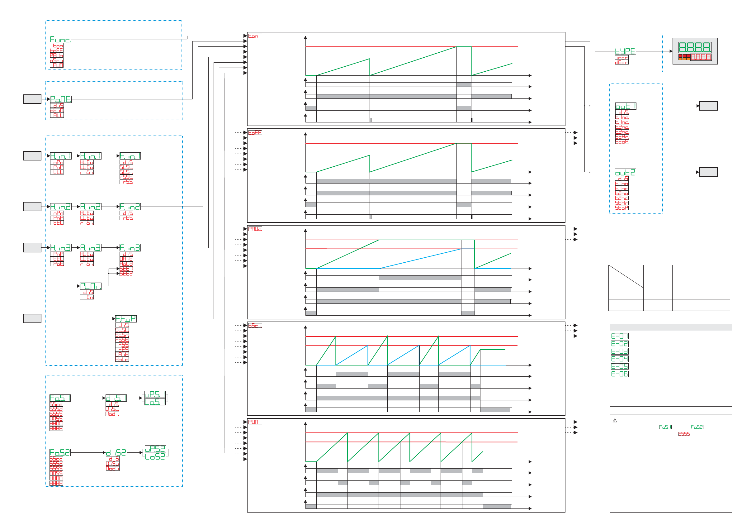
FUNCTION CONFIGURATION
P-01
Timer
Function
Timer On (Note 1)
Timer Off
(Note 1)
Pause/Work
Oscillator
PWM
(Note 1)
BACKUP MEMORY CONFIGURATION
P-02
Power-off
POWER-ON
RESET
Memory
Disabled
Only Timer
Timer / State
INPUT CONFIGURATION
P-03
Hardware
Input 1
P-06
Active State
Input 1
P-09
Function
Input 1
I1
NPN
PNP
TTL
P-04
Hardware
Input 2
High Level
Low Level
Rising edge
P-07
Active State
Input 2
Disable
Start / Stop
Start / Stop-Reset
Reset-Start / Stop
Reset / Start / Stop
P-10
Function
Input 2
(Note 2)
(Note 3)
(Note 4)
(Note 5)
I2
NPN
PNP
TTL
P-05
Hardware
Input 3
High Level
Low Level
Rising edge
P-08
Active State
Input 3
P-11
Function
Input 3
Disabled
Reset
I3
PNP
TTL
Potent.
Key UP
SETPOINT CONFIGURATION
P-16
Format
Set 1
Second,Hundredth
Second,Tenth
Second
Minute,Second
Hour.Minute
Hour
P-17
Format
Set 2
Second,Hundredth
Second,Tenth
Second
Minute,Second
Hour,Minute
Hour
Note 1:
In this timer mode, if P-06 Active State Input 1 = Rising Edge or P-09 Function Input 1 = Disable,
at the end of the count (reaching the set), the timer automatically goes to STOP.
Note 2:
This function does not reset the timer value, therefore requires an input for reset.
Note 3:
This function resets the timer at the instant of the STOP command.
Note 4:
This function resets the timer at the instant of the START command.
Note 5:
This function is active only if P-06 Active State Input 1 = Rising Edge
High Level
Low Level
Rising edge
P-24
Potentiometer
calibration
Disable
Enable
P-18
Display
Set 1
P-19
Display
Set 2
Disabled
Wait
Hold
Potent. To SET1
Potent. To SET2
P-12
Function
Key UP
Disabled
Start / Stop
Start / Stop-Reset
Reset-Start / Stop
Reset / Start / Stop
Reset
Wait
Hold
Disabled
Visualized
Modifiable
Disabled
Visualized
Modifiable
(Note 2)
P-21
Upper limit
Set 1
P-20
Lower limit
Set 1
P-23
Upper limit
Set 2
P-22
Lower limit
Set 2
(Note 3)
(Note 4)
Timer On
Stop/Reset
Start/Stop/Reset
Reset
Wait/Hold/Set1-2
Start/Stop/Reset/Wait/Hold
Set1
Set2
Out Timer 1
Timer Off
Stop/Reset
Start/Stop/Reset
Reset
Wait/Hold/Set1-2
Start/Stop/Reset/Wait/Hold
Set1
Set2
Out Timer 1
Pause / Work
Stop/Reset
Start/Stop/Reset
Reset
Wait/Hold/Set1-2
Start/Stop/Reset/Wait/Hold
Set1
Set2
Out Timer 1
Out Timer 2
Oscillator
Stop/Reset
Start/Stop/Reset
Reset
Wait/Hold/Set1-2
Start/Stop/Reset/Wait/Hold
Set1
Set2
Out Timer 1
Out Timer 2
PWM
Stop/Reset
Start/Stop/Reset
Reset
Wait/Hold/Set1-2
Start/Stop/Reset/Wait/Hold
Set1
Set2
Out Timer 1
Out Timer 2
Start
Stop
Reset
Start
Stop
Reset
Start
Stop
Start
Stop
Start
Stop
SetSet
SetSet
SetSet
SetSet
SetSet
TI327401 “TIMER”
DISPLAY CONFIGURATION
Timer value
SET1
Out Timer 1
Out Timer 2
TIMER 1TIMER 1
1
0
1
0
1
0
1
0
Time
Timer value
SET1
Out Timer 1
Out Timer 2
TIMER 1TIMER 1
1
0
1
0
1
0
1
0
Time
Timer value
TIMER 1TIMER 1
SET1
Out Timer 1
Out Timer 2
SET2
TIMER 2TIMER 2
1
0
1
0
1
0
1
0
Time
Timer value
TIMER 1TIMER 1
SET1
Out Timer 1
Out Timer 2
SET2
TIMER 2TIMER 2
1
0
1
0
1
0
1
0
Time
Timer value
TIMER 1
TIMER 1
SET2 (Period)SET2 (Period)
Out Timer 1
Out Timer 2
SET1(% duty-Cycle)SET1(% duty-Cycle)
1
0
1
0
1
0
1
0
Time
P-15
Type
of Timer
Incremental
Decremental
123
OUTPUT CONFIGURATION
P-13
Output Q1
Setup
Q1
Disabled
Out Timer 1 n.o.
Out Timer 1 n.c.
Out Timer 2 n.o.
Out Timer 2 n.c.
Start
Stop
P-14
Output Q2
Setup
Q2
Disabled
Out Timer 1 n.o.
Out Timer 1 n.c.
Out Timer 2 n.o.
Out Timer 2 n.c.
Start
Stop
LOGIC
LEVEL
H
L
INPUT
TYPE
NPN
INPUT
< 4,7 v
> 5,7 v
TABLE of ERROR MESSAGESTABLE of ERROR MESSAGES
ERROR in WRITING of EEPROM Memory (Note 1)
ERROR in READING of EEPROM Memory
Incorrect parameters
Incorrect calibration data (Note 1)
Incorrect status data (Note 1)
Incorrect BACKUP registersI (Note 2)
Note 1:
Switch the device off and restart it; if error is still notified,
contact technical service
Note 2:
Discharged battery: keep the device connected to power supply in
order to recharge the battery.
In PWM mode, the only option available
on parameters 16 and 17 for
format of SET1 and SET2 is (seconds).
Low and upper limits for SET1 (related to
percentage of work or Duty Cycle) are allowed
in the range 0 ...100 (%).
PNP
INPUT
>5,7 v (I1, I2)
>12,4 v (I3)
< 4,7 v (I1, I2)
< 10,2 v (I3)
(Note 1)
TTL
INPUT
>2,5 v
< 2,0 v
 Loading...