

MANUAL RATE METER
MANUAL RATE METER
TA327401
TA327401
Wachendorff Prozesstechnik GmbH & Co. KG www.wp-direkt.de
e-mail: RSS@wachendorff.de
Version 2.0
INTRODUCTION
Thanks for choosing a Wachendorff Prozesstechnik device.
The tachometer TA327401 allows to read the frequency (max 100 kHz) of a
signal from single or double (bidirectional encoder) input.
2 universal digital inputs are available (NPN/PNP ) for
/potential free contact
external commands like output activation or Hold/ Stop current visualization;
one input is also analogue in order to allow setpoint modification by external
potentiometers.
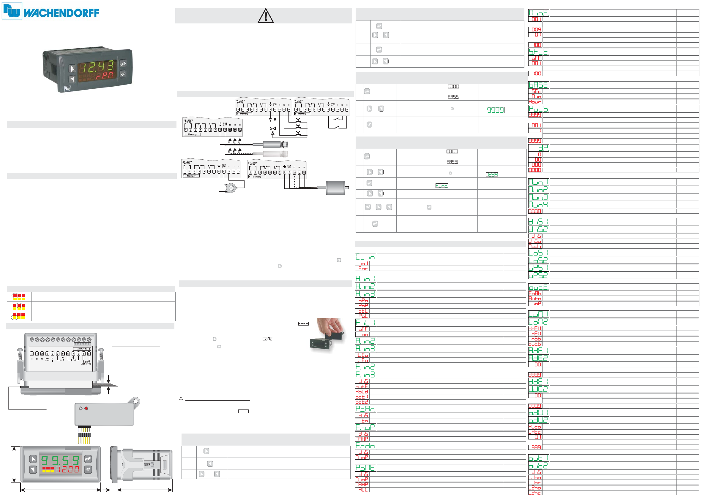
TECHNICAL DATATECHNICAL DATA
Operating
Conditions
Sealing
Material
Outputs
OUT 24V
Back-UP
Power Supply
LED
123
123
123
MEANING
Operating temperature: 0 °C to 40 °C,
humidity 35 uR% to 95 uR%
Front panel: IP65 (with gasket) ,
Box: IP30, Terminal blocks: IP20
PC ABS UL94V0 self-extinguishing
3 PNP/NPN configurable as analogue for potentiometers.
Digital
(max 28 Vdc in PNP mode)
Inputs
2 relays 5A resistive charge
30mA(at 24 VAV supply),40 mA(at 24 VDC supply),60
mA (at 110 to 230 VAC)
.
Rechargeable battery, approx. 7 days autonomy
24 to 230 VAC/VDC +/-15 % 50/60 Hz/2W
Report the activation of Q1
Report the activation of Q2
Report serial transmission by the TA327401
SIZE AND INSTALLATIONSIZE AND INSTALLATION
Frontal panel cut-out
28.5 mm x 70.5 mm
2mm
÷8
Suggested thickness
7
53 mm
Gasket for 32 x 74
35 mm
Q2
Q2
MEMORYC.121MEMORYC.121
42 mm pins
Memory Card
123
77 mm
1/2HP
1/2HP
Resistive
Resistive
5A230V
5A230V
Q1
Q1
1/2HP
1/2HP
U1
Resistive
Resistive
5A230V
5A230V
1 6
CN1
Memory Card (optional)
with battery SFUR0KIT
Read carefully the safety guidelines and programming instructions
contained in this manual before using/connecting the device.
Disconnect power supply before proceeding to hardware settings or
electrical wirings.
Only qualified personnel should be allowed to use the device and/or
service it and in accordance to technical data and environmental
conditions listed in this manual.
Do not dispose electric tools together with household waste materials in
observance of European Directive 2002/96/CE
WIRING DIAGRAMWIRING DIAGRAM
PNP
NPN
Potentiometer:
+-
POTENTIOMETER 0 to 5/10 Kohm
Resolution 1000 steps.i
Proximity
OUT
Sensor PNP
3 wires
Proximity
OUT
Sensor PNP
2 wires
GND
Fase Z
Fase A
Fase B
POSITIVO
To modify Set1 or Set2 by external potentiometer followthesteps below:
1
- use potentiometers 0 kOhm to 5/10 kOhm
2
- connect cursor to pin I3; a wrong connection may damage the potentiometer and
lead to lock of the device.
3
- accuracy on input is max 1000 points, therefore set the parameters "Upper limit"
and "Lower limit" with a max difference of 1000 units.
(Ex.: LoS1 to 50,0 and uPS1 to 150,0 to modify setpoint value related to Set1
between 50 and 150 steps with steps of one tenth). Greater differences would make
unstable the less significant digit.
4
- To calibrate the scale of potentiometer enter theconfigurationmodeandselect:
Hin.3 as Pot Fin.3 as Set1 or Set2 P.tAr as Enable
Exit configuration mode and place potentiometer at minimum level and press key,
then place potentiometerat max level and press key: the deviceautomatically exit
the calibration procedure.
N.B.:Aswitch-off ofthedevicewouldinterrupt the calibration.
PNP
NPN
Encoder
MEMORY CARD (optional)MEMORY CARD (optional)
Parameters and setpoint values can be copied from one device to another using
the Memory card
There are two methods:
With the device connected to the power supply
>
insert the memory card .
On activation display 1 shows and display 2 shows
(Only if the values stored on Memory Card are correct).
By pressing the key display 2 shows
Confirm using the key .
The device loads the new data and starts again
With the controller disconnected from the power supply:
>
The memory card is equipped with an internal battery with a life of about 1000 uses.
Insert the memory card and press the programming button.
When writing the parameters, the LED turns red and on completing the procedure
it changes to green. It is possible to repeat the procedure.
UPDATING MEMORY CARD.
update
To the memory card values, follow the procedure described in the first
method, setting display 2 to so as not to load the parameters on controller.
Enter configuration and .
Exit configuration. Changes are saved automatically.
MAXIMUM AND MINIMUM PEAK FUNCTIONMAXIMUM AND MINIMUM PEAK FUNCTION
1
2
3
.
Attention: Perform first an update of the programm module.
when the controller is off
MemO
.
change at least one parameter
PRESS
and
If enabled maximum peak function, maximum peak
value obtained is visualized.
If enabled minimum peak function, minimum peak
value obtained is visualized.
If enabled peak function, minimum and maximum peak
value will initialize to current tachometer value.
DISPLAY
SETPOINT MODIFICATIONSETPOINT MODIFICATION
PRESS DISPLAY
1
2
2a
3a
or
or
Visualizes SETPOINT 1 / 2
Modifies selected SET
Selects chosen digit
Modifies blinking digit
of selected SET
LOADING DEFAULT SETTINGSLOADING DEFAULT SETTINGS
1
2
3
PRESS
for 3 seconds
Modify blinking digit, pass to the
or
to confirm
DISPLAY DO
Display 1 shows
with 1st digit blinking, while
Display 2 shows
next digit pressing
The device loads
default settings
CONFIGURATION PARAMETER MODIFICATIONCONFIGURATION PARAMETER MODIFICATION
1
2
3
4
5
6
PRESS
for 3 seconds
or
to confirm
or
+
or
Modify blinking digit, pass to the
Display shows first parameter of
configuration table
Increase or decrease value on display
pressing and an arrow key
the device exits from programming mode.
DISPLAY DO
Display 1 shows
with 1st digit blinking, while
Display 2 shows
next one pressing
Scroll parameters
End of configuration,
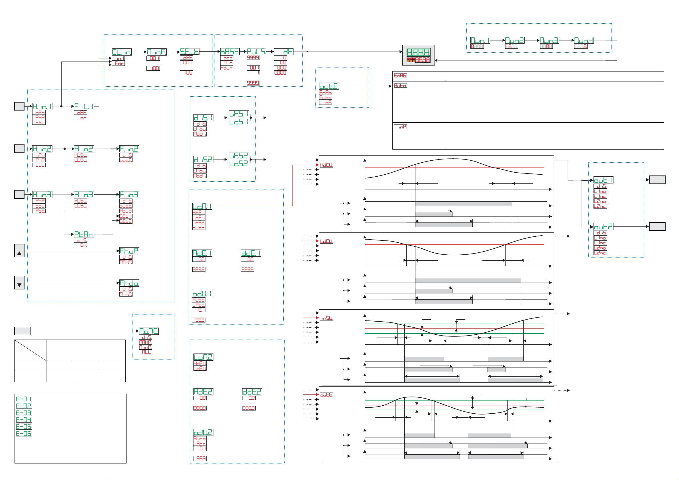
PARAMETERS LISTPARAMETERS LIST
CLOCK INPUT CONFIGURATION
P-01 Clock Input
I1
Encoder
INPUT CONFIGURATION
P-02 Hardware input 1
P-03 Hardware input 2 Input 2 hardware configuration
P-04 Hardware input 3 Input 3 hardware configuration
NPN
PNP
TTL
Potent.
P-05 Filter Input 1 Input 1 hardware filter configuration
Off
On
P-06 Active State Input 2 Input 2 active state
P-07 Active State Input 3 Input 3 active state
High Level
Low Level
P-08 Function Input 2 Function associated to Input 2
P-09 Function Input 3 Function associated to Input 3
Disable
Out Enable/Disable
Hold (only for I3)
Set1 (only for I3)
Set2 (only for I3)
P-10 Potentiom. Tarature Potentiometer calibration procedure
Disable
Enable
P-11 Function Key UP Function associated to key UP (up arrow)
Disable
Display max peak
P-12 Function Key DOWN Function associated to key DOWN (down arrow)
Disable
Display min peak
BACKUP MEMORY CONFIGURATION
P-13 Power-off Memory
Disable
Min Peak
Max Peak
All Peak
Input signal selection
Input signal on I1
Input signal on I1 and I2 (bidirectional encoder)
Input 1 hardware configuration
NPN (not available on input 3)
PNP
TTL
Potentiometer (available only for input 3)
Input hardware filter desabled
Input hardware filter enabled (22nF)
High level
Low level
Disabled
Enable / Desable tachometer outputs
Hold visualized tachometer value
Set1 setting by potentiometer
Set2 setting by potentiometer
Disabled
Enabled
Disabled
Max. registered peak visualization (reset by UP+DOWN key)
Disabled
Min. registered peak visualization (reset by UP+DOWN key)
Power-off memory
No peak value stored at switch-off
Minimum peak value stored at switch-off
Maximum peak value stored at switch-off
Max. and Min. peak values stored at switch-off
Enter password
Switch the device off
and restart it
Enter password
Enter the new data
that will be stored
when releasing the keys
Default
Default
Default
Default
Default
Default
Default
Default
Default
CLOCK INPUT CONFIGURATION
P-14 Minimum Input Frequency
0.01 Hz
...
0.09Hz
0.1 Hz
...
10.0Hz
P-15 Software Filter Sampling frequency software filter
off
0.01 sec
...
1.00 sec
Lower frequency visualized
For lower frequency values 0 is visualized on display.
This parameter forces max. refresh time of display
from 100 to 0.1 sec.
No software filter on reading
Mean realized on samplings done within time set
in this parameter. Display will be updated according to
this time range.
DISPLAY CONFIGURATION
P-16 Timebase Visualization time base
sec
min
hour
P-17 Pulse in Unit Impulses on visualized unit
99.99 pulse
...
0.01 pulse
1 pulse
...
9999 pulse
P-18 Decimal Point Tachometer value visualization format
0
0.0
0.00
0.000
Visualized value referred to the second
Visualized value referred to the minute
Visualized value referred to the hour
Number of impulses for single unit. For example,
in speed measurement, it indicates how many
Impulses correspond to a full revolution.
No decimal digit visualization
1 decimal digit visualization
2 decimal digits visualization
3 decimal digits visualization
MEASURE UNIT CONFIGURATION
P-19 Measure Unit 1 Setting digit 1 of displayed measuring unit
P-20 Measure Unit 2 Setting digit 2 of displayed measuring unit
P-21 Measure Unit 3 Setting digit 3 of displayed measuring unit
P-22 Measure Unit 4 Setting digit 4 of displayed measuring unit
Edit digits
Set each of 4 digits as chosen
SETPOINT CONFIGURATION
P-23 Display Set 1 Setpoint 1 display selection
P-26 Display Set 2 Setpoint 2 display selection
Disable
Visualized
Modifiable
P-24 Lower Limit Set 1 Set 1 minimum value (0...9999)
P-27 Lower Limit Set 2 Set 2 minimum value (0...9999)
P-25 Upper Limit Set 1 Set 1 maximum value (0...9999)
P-28 Upper Limit Set 2 Set 2 maximum value(0...9999)
Setpoint value not visualized
Setpoint value visualized
Setpoint value visualized and modifiable
OUTPUT ENABLE CONFIGURATION
P-29 Output Enable Outputs enabled
Always enable
Automati enable
Enable by input
TACHOMETER LOGIC OUTPUT MODE CONFIGURATION
P-30 Logic Output Mode1
P-34 Logic Output Mode2
High Deviation
Low Deviation
Inside Band
Out of Band
P-31 Activation Delay 1
P-35 Activation Delay 2
0.0 sec
to
999.9 sec
P-32 Deactivation Delay 1
P-36 Deactivation Delay 2
0.0 sec
to
999.9 sec
P-33 Output 1 Duration
P-37 Output 2 Duration
Automatic
Latch output (clear by FNC key)
Pulse 0.1 sec
to
Pulse 99.9 sec
Tachometer outputs always enabled
Outputs enabled automatically
Tachometer outputs enabled by digital inputs
Tachometer logic output mode 1
Tachometer logic output mode 2
Active output with high deviation
Active output with low deviation
Active output inside band
Active output out of band
Logic output 1 activation delay
Logic output 2 activation delay
Defines logic output activation delay.
Setting range from 0.0 sec
to 999.9 sec.
Logic output 1 deactivation delay
Logic output 2 deactivation delay
Defines logic output deactivation delay.
Setting range from 0.0 sec
to 999.9 sec.
Tachometer logic output 1 duration
Tachometer logic output 2 duration
Automatic output duration
Latch output, reset by FNC
0,1 sec output impulse duration
99,9 sec output impulse duration
OUTPUT CONFIGURATION
P-38 Output Q1 Setup Relay Q1 output setting
P-39 Output Q2 Setup Relay Q2 output setting
Disable
Logic Out 1 n.o.
Logic Out 1 n.c.
Logic Out 2 n.o.
Logic Out 2 n.c.
Disabled output
Logic output 1 on n.o. contact
Logic output 1 on n.c. contact
Logic output 2 on n.o. contact
Logic output 2 on n.c. contact
Default
Default
Default
Default
Default
Default
Default ----
Default Set2
Default Set1
Default 0
Default 0
Default 999
Default 999
Default
Default
Default
Default
Default
Default 2
Default 1
CLOCK INPUT CONFIGURATION
P-01
Clock
Input
P-14
Minimum Input
Frequency
P-15
Software
Filter
TA327401 “RATE METER”
DISPLAY CONFIGURATION
P-16
Timebase
P-17
Pulses
in Unit
P-18
Decimal
Point
MEASURE UNIT CONFIGURATION
P-19
Measure
Unit 1
edit digit 1
P-20
Measure
Unit 2
edit digit 2
P-21
Measure
Unit 3
edit digit 3
P-22
Measure
Unit 4
edit digit 4
INPUT
CONFIGURATION
P-02
Hardware
Input 1
P-05
Filter
Input 1
I1
NPN
PNP
TTL
P-03
Hardware
Input 2
Off
On
P-06
Active State
Input 2
I2
NPN
PNP
TTL
P-04
Hardware
Input 3
High Level
Low Level
P-07
Active State
Input 3
I3
PNP
TTL
Potent.
Key
Key
POWER-ON
RESET
LOGIC
LEVEL
H
L
INPUT
TYPE
NPN
INPUT
< 4,7 v
> 5,7 v
TABLE OF ERROR MESSAGESTABLE OF ERROR MESSAGES
ERROR IN WRITING OF EEPROM MEMORY (Note 1)
ERROR IN READING OF EEPROM MEMORY (Note 1)
INCORRECT PARAMETERS (Note 1)
INCORRECT CALIBRATION DATA (Note 1)
INCORRECT STATUS DATA (Note 1)
INCORRECT BACKUP REGISTERS (Note 2)
Note 1:
SWITCH THE DEVICE OFF AND RESTART IT; IF ERROR IS
STILL NOTIFIED, CONTACT TECHNICAL SERVICE.
Note 2:
DISCHARGED BATTERY. KEEP THE DEVICE CONNECTED
TO THE POWER SUPPLY IN ORDER TO RECHARGE THE
BATTERY.
High Level
Low Level
P-10
Potentiometer
calibration
Disable
Enable
PNP
INPUT
>5,7 v (I1, I2)
>12,4 v (I3)
< 4,7 v (I1, I2)
< 10,2 v (I3)
TTL
INPUT
>2,5 v
< 2,0 v
I1
Encoder
P-08
Function
Input 2
Disable
Out Enable/Disable
P-09
Function
Input 3
Disable
Out Enable/Disable
Hold Display Value
Set1
Set2
P-11
Function
Key UP
Disable
Display max peak
P-12
Function
Key DOWN
Disable
Display min peak
BACKUP MEMORY
CONFIGURATION
P-13
Power-off
Memory
0.01 Hz
to
10,0 Hz
Disable
Max Peak
Min Peak
All Peak
off
0.01 sec
...
1.00 sec
sec
min
hour
99.99
to
0.01
1
0
0.0
0.00
0.000
to
9999
SETPOINT CONFIGURATION
P-25
P-23
Display
Set 1
Disable
Visualized
Modifiable
P-26
Display
Set 2
Disable
Visualized
Modifiable
TACHOMETER LOGIC OUTPUT MODE CONFIGURATION
P-30
Logic Output
Mode 1
Upper limit
Set 1
P-24
Lower limit
Set 1
P-28
Upper limit
Set 2
P-27
Lower limit
Set 2
Set1
Set2
High Deviation
Low Deviation
Inside Band (Band defined by SET2)
Out of Band (Band defined by SET2)
P-31
Activation
Delay 1
0.0 sec
...
999.9 sec
P-33
Output 1
Duration
P-32
Deactivation
Delay 1
0.0 sec
...
999.9 sec
Automatic
Latch output (clear only by FNC key)
Pulse 0.1 (sec)
to.
Pulse 99.9
TACHOMETER LOGIC OUTPUT MODE CONFIGURATION
P-34
Logic Output
Mode 2
(sec)
High Deviation
Low Deviation
P-35
Activation
Delay 2
0.0 sec
...
999.9 sec
P-37
Output 2
Duration
P-36
Deactivation
Delay 2
0.0 sec
...
999.9 sec
Automatic
Latch output (clear only by FNC key)
Pulse 0.1 (sec)
to
Pulse 99.9 (sec)
OUTPUT ENABLE
CONFIGURATION
P-29
Output
Enable
Always enable
Automatic enable
Enable by Input
Tach. Value
Activation delay
Deactivation delay
Output duration
Set
Logic output
Output
duration
mode
Tach. Value
Activation delay
Deactivation delay
Output duration
Set
Logic output
Output
duration
mode
Tach. Value
Activation delay
Deactivation delay
Output duration
Set1
Set2
Logic output
Output
duration
mode
Tach. Value
Activation delay
Deactivation delay
Output duration
Set1
Set2
Logic output
Output
duration
mode
Tach.
Value
Auto
Latch
Pulse
Tach.
Value
Auto
Latch
Pulse
Tach.
Value
Auto
Latch
Pulse
Tach.
Value
Auto
Latch
Pulse
1
0
1
0
1
0
1
0
1
0
1
0
1
0
1
0
1
0
1
0
1
0
1
0
Out Enable
Activation
delay
Activation
delay
123
Always enable
Automatic enable
Enable by input
Activation
delay
Clear by FNC Key
Pulse duration time
Activation
delay
Clear by FNC Key
Pulse duration time
Clear by FNC Key
Pulse duration time
Deactivation
delay
Clear by FNC Key
Pulse duration time
TACHOMETER OUTPUTS ARE ALWAYS ENABLED.
DEPENDING ON LOGIC OUTPUT MODE PARAMETER, THEREARE DIFFERENT OPERATING MODES:
- : OUTPUTS ARE ALWAYS ENABLED
High Deviation
- : AT STARTING, OUTPUTS ARE DESABLED; THEY CAN BE ENABLED WHEN TACHOMETER VALUE OVERCOMES
Low Deviation
SETPOINT VALUE AND KEPT ENABLED UNTIL INPUT SIGNAL FALLS BELOW VALUE SET ON PARAMETER «MINIMUM INPUT
FREQUENCY» (P-14);
- : OUTPUTS ARE ALWAYS ENABLED
Inside Band
- : AT STARTING OUTPUTS ARE DESABLED, THEY CAN BE ENABLED WHEN TACHOMETER VALUE OVERCOMES
Out of Band
SET1-SET2 VALUE, AND KEPT UNITL INPUT SIGNAL FREQUENCY FALLS BELOW VALUE SET ON PARAMETER «MINIMUM INPUT
FREQUENCY»
TACHOMETER OUTPUTS ARE ENABLED TO OPERATE ONLY IF:
- INPUT 2 FUNCTION IS SET ON AND INPUT
IS ACTIVE
- INPUT 3 FUNCTION IS SET ON AND INPUT
IS ACTIVE
(P-14);
OUT ENABLE/DISABLE
Out Enable/Disable
Deactivation
delay
Tach. Value
SET
Tach.
Value
SET
Time
Logic
Out
Logic
Out
OUTPUT RELAIS
CONFIGURATION
P-38
Output Q1 (relay)
Setup
Disable
Logic Out 1 n.o.
Logic Out
Logic Out
Logic Out
P-39
Output Q2 (relay)
Setup
Disable
Logic Out 1 n.o.
Logic Out 1 n.c.
Logic Out 2 n.o.
1 n.c.
2 n.o.
2 n.c.
Logic Out 2 n.c.
Deactivation
delay
Time
Logic
SET2SET2
Deactivation
delay
Activation
delay
Clear by FNC Key
Pulse duration time
Tach. Value
SET1
Deactivation
delay
Out
Time
Logic
SET2SET2
Activation
delay
Pulse duration time
Deactivation
delay
Clear by FNC Key
Tach. Value
SET1
Out
Time
Q1
Q2
 Loading...