


4211-7, S.7
Operation & Maintenance Instruction
Page 1 of 10
September, 2017
VX™ VENT VALVE PORTION, PART NO.
SEPTEMBER, 2017
Supersedes issue dated December, 2003
NOTE: The following description and
operation
components being new or this device
its components having been repaired,
tested, installed and maintained in
accordance with instructions issued by
this and any other applicable Wabtec
Corporation
replaced in this device, the operation of the
complete device must pass a series of
tests prescribed in the latest issue of the
applicable Wabtec Test Specification. At the
time this device is applied to the brake
equipment arrangement, a stationary
vehicle test must be made to insure that this
device functions properly in the total brake
equipment arrangement. (Consult your
local Wabtec Corporation
Representative for identity of the test
specification, with latest revision date, that
covers this device.)
IMPORTANT: Only Wabtec Corporation
supplied parts are to be used in the repair
of this device in order to obtain satisfactory
operation. Commercially available nonO.E.M. parts are unacceptable.
NOTE: The part numbers and their
associated descriptions are the property of
Wabtec Corporation and may not be
replicated in any manner or form without
the prior sole written consent of an Officer of
Wabtec Corporation.
is
based
on this
device
and its
and
publications.
WARNING: At the time any part is
™ Trademark of Wabtec Corporation
© 2017 Wabtec Corporation. All rights reserved
699505
4211-7, S.7
Operation & Maintenance Instruction
September, 2017
Page 2 of 10
NOTE: The
following description
and
operation
is based on
this device and its components having been repaired, tested,
installed and maintained in accordance with instructions of
this and any other applicable publications issued by the
Wabtec Corporation, or its predecessor, the Westinghouse
Air Brake Company.
1.0 DESCRIPTION
The VX Vent Valve Portion is a double
which, when properly installed and
deplete brake pipe air locally at a rapid rate to assist in
propagating
an
emergency
brake
main line of brake pipe is reduced at an emergency rate.
The VX Vent Valve Portion features increased emergency
venting capacity and jump distance capabilities. A unique
diaphragm
design
incorporated
the need for a separate venting piston and provides a self-
diaphragm
maintained,
application
type valve
functions to
whenever the
within the Portion eliminates
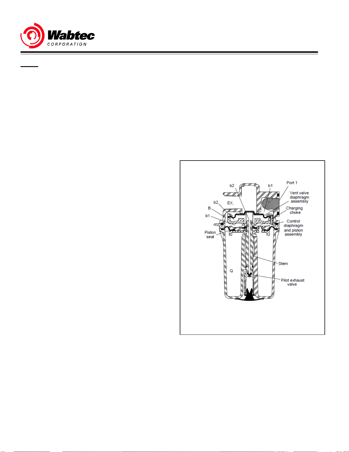
2.1
RELEASE AND
RUNNING
Brake pipe air under
the metal screen filter into cavity b, on the non-spring side of
the vent valve
cavity b1, above the
past the control piston seat of the body and into cavity b2 on
the spring side of the vent valve diaphragm assembly. Brake
pipe air flow continues through the passage in the seated
piston where it is blocked by the exhaust valve. Brake pipe
air under pressure in cavity b1 flows through the charging
choke into the control pressure volume Q.
pressure
entering Port 1 flows through
diaphragm assembly,
control diaphragm
through passage B into
and piston assembly,
purging action. Operation of a VX
Vent Valve Portion at one
location (in a train consist) aids in producing an emergency
rate of brake pipe reduction at the next locomotive unit or car
and action of the Vent Valve
Portion
on each
succeeding
unit
or car assists in a fast transmission of an emergency brake
signal through an open train line pipe.
The VX Vent Valve Portion is designed so that it can be
readily removed from the pipe bracket, laminate, mounting
plate, or branch pipe tee on which it is mounted, for
maintenance or repair. Provision is made for the attachment
of a vent protector arrangement at the exhaust port of the
Portion body.
The VX Vent Valve Portion may be used in equipment
arrangements where the air pressure does not exceed 150
psig. Special installation procedures are required when
installing the VX Vent Valve Portion in specific equipment
arrangements. Consult your Wabtec Corporation
Representative for information on your required applications.
2.0 OPERATION
NOTE: The views shown in Figures 1, 2, 3 and 4 are
diagrammatic representations for functional analysis only.
They are not to be used as actual physical representations
of the VX Vent Valve Portion.
Figure 1 - Release and
Diagrammatic View
Running

4211-7, S.7
Operation & Maintenance Instruction
Page 3 of 10
September, 2017
2.2
EMERGENCY - FIRST
STAGE
When an emergency rate of brake pipe reduction occurs,
the brake pipe
rapidly
creating a
in cavities b, b1 and b2 and the air pressure in the control
pressure volume
piston
assembly
seat
on
seat of the body. The
from cavity b1. Air pressure in cavity b2 is then directed to
exhaust through
the exhaust valve. Cavity b2 is
small
volume.
air
pressure
in cavities b, b1
differential between the brake pipe
Q. This
to move,
causes
the
unseating
control diaphragm
the piston stem from its
the exhaust valve and seating the
the
seating
passage
of the piston
in the
unseated
exhausted quickly
and
b2 is reduced
piston on
isolates
piston stem at
pressure
the
piston
cavity b2
due to its
2.3
EMERGENCY - SECOND
STAGE
The rapid exhaust of air pressure from cavity b2 creates a
differential on th e non-spring side
assembly causing
and connects brake pipe
and
to exhaust (Port EX). Air pressure in the control pressure
this
assembly
air from port 1
volume Q then flows to atmosphere through the charging
choke of the control piston, cavity b1, passage B, cavity b
and port EX, when the air pressure in the control pressure
volume
Q is vented, the vent
the control diaphragm and piston
the
Release
Position by the force exerted by the spring.
of
the
vent
valve
to move
away
and
cavities b
valve diaphragm assembly
assembly
are returned to
diaphragm
from its seat
and
b1
and
Figure 2 - Emergency Position - 1st
Diagrammatic View
Stage
Figure 3 - Emergency Position - 2nd
Stage
Diagrammatic View

4211-7, S.7
Operation & Maintenance Instruction
September, 2017
Page 4 of 10
3.0
MAINTENANCE
SCHEDULE
3.1 IMPORTANT: The VX
from the
completely disassembled, the parts cleaned, inspected,
lubricated and then reassembled using NEW Wabtec
Corporation rubber
parts as specified in accordance with the
application schedule,
so indicate. The assembled portion is then to be tested for
correct operation.
equipment arrangement
parts
Vent Valve
and other
or more
Portion is to be removed
and taken to the shop, be
NEW
Wabtec Corporation
following
frequently,
if service conditions
vehicle
Recommended
Type of Application Least Once
Frequency
- At
Every
Freight Cars 120 Months
Locomotives 12 Months
Passenger
Transit 24 Months
(Interstate) 36 Months
4.0
PARTS CATALOG AND REPLACEMENT
PARTS
4.1
PARTS
CATALOG
4.1.1 IMPORTANT: When ordering replacement parts for
the VX Vent Valve Portion,
issue of the Wabtec
Part No. 699505, refer to the
Corporation
Parts
Catalog
current
3211-7, S.7.
NOTE: The reference numbers used in the Parts Catalog
and those used in this
number and the descriptive part name to be sure that the
desired
part is ordered.
publication may
differ.
Check
the part
4.2
REPLACEMENT
PARTS
4.2.1 IMPORTANT: To obtain satisfactory operation and
reliability of the VX Vent Valve Portion, ONLY Wabtec
Corporation replacement parts are to be used in the
maintenance
of this portion.
5.0
SAFETY PROCEDURES AND
WARNINGS:
The following
wherever the symbol appears in the maintenance
procedures. Failure to observe these
result in serious injury to those performing the work
and/or bystanders.
statements
WARNINGS
of warning
apply
all or in part
precautions
may
• The use of an air jet, which must be less than 30
p.s.i.g., to blow parts clean or to blow them dry
after being cleaned with a solvent will cause
particles of dirt and/or droplets of the cleaning
solvent to be airborne. Wire brushing may also
cause particles of dirt, rust, and scale to become
airborne. These conditions may cause skin and/or
eye irritation.
• When using an air jet, do not direct it toward
another
in bodily injury.
person.
Improper
use of air jet could result
• Personal eye protection must be worn when
performing any work on this device or its
components parts to avoid any possible injury to
the eyes.
• The use of
of lubricants can involve health and/or safety
hazards. The manufacturers of the solvents and
lubricants should
as OSHA Form OSHA-20 or its equivalent). The
recommended precautions and procedures of the
manufacturers should be followed.
solvents
be
as
cleaning
contacted
agents and the use
for
safety
data (such
• When performing any test or work on devices or
equipment while they are on the vehicle (on car
test, etc.)
that vehicle movement will not occur which could
result in injury to personnel and/or damage to
equipment.
special precautions must be taken to
insure
• Assembly may be under a spring load. Exercise
caution during disassembly so that no parts "Fly
Out" and cause bodily injury.
• All air supply and/or electric current to this device
and/or to an y components part must be cut-off
before this device and/or any component part is
removed from the equipment arrangement.
• "Bottled" up air under pressure (even though air
supply
of dirt to
level when this device and/or any component part
is removed from the equipment arrangement.
is cut-off)
become airborne
may cause gaskets and/or
and an
increase
particles
in sound
• Personal eye and ear protection must be worn and
care
taken
to
avoid possible injury
any work on this device and/or component part.
when performing

4211-7, S.7
Operation & Maintenance Instruction
Page 5 of 10
September, 2017
• To prevent receiving electrical shock when
performing electrical test, hands must be clear of
electrical components, contacts and housing and
the required "in-lab" grounding procedures must
be
strictly adhered
be used.
in severe injury or death.
Failure
to.
A wooden
to heed this
work
bench
WARNING could
should
result
• An adequate support or lifting device must be
available to support the Device and/or Valve
Portion(s) during removal, installation and
maintenance procedures.
6.0
CLEANING
SPECIAL
SOLVENT,
TOOLS
LUBRICANT, SEALANT
AND
6.1.1 The
Vent Valve Portion
such as mineral spirits or naptha, that will dissolve oil or
grease and that will permit the parts to be cleaned without
abrasion.
solvent
used to
MUST BE an aliphatic hydrocarbon
clean
the
reusable
parts of the VX
solvent,
IMPORTANT: Cleaning solvents are to be used in a well
ventilated
area.
6.2 LUBRICANTS
6.2.1 Number 2 Silicone Grease, Wabtec Corporation
Specification
such as Dow Corning Corporation Dow Corning 55,
for the
o-ring bearing surfaces of the bushing(s) which will be in
contact with the o-rings.
M-7680-2,
lubrication
(Industry Designation
of specified o-rings, o-ring grooves
MIL-G-4343),
is required
and
6.2.2 A
Corporation
913), such as Super Flake Graphite Company - Superfine
Number 597 Joseph Dixon Crucible Company - Microfyne
Graphite or National Carbon Company Number 38 or 39
Graphite, and two parts of SAE-20 oil by weight is required
for
choke plug prior to the installation of this choke plug in the
piston.
compound consisting
Specification M-7695-2, (AAR Specification M-
the lubrication
of
the threads
of
one part
of
the cleaned
of graphite, Wabtec
or
NEW
piston
6.3.1
Locking Sealant,
7499-05,
application to the threads of the piston stem prior to the
installation of the piston jam nut.
such as Loctite
Wabtec
Corporation Specification
Corporation
TL-242, is
required
7.0
MAINTENANCE
PROCEDURES
NOTE: When performing the procedures which
NOT use hard or sharp tools to remove o-rings, gaskets,
seals or the diaphragms. Exercise care so that no damage
is done to
reusable
parts.
WARNING; When
follow, springs within the assembly may be placed
under compression. Exercise care so that no parts are
inadvertently expelled. Inadvertently expelled parts
may cause bodily injury and/or damage to parts.
performing
the
procedures
7.1 DISASSEMBLY
NOTE: The VX Vent Valve Portion
pounds.
weighs approximately
7.1.1 If the mounting gasket is still in its groove in the
mounting face of the body (2), it is to be removed and
SCRAPPED. The
Portion and is not illustrated.
gasket IS
NOT a part of the
VX Vent
7.1.2
its port in the body (2).
Remove
and
SCRAP
the wire mesh strainer (3) from
7.1.3 Remove the four 3/8" x 11/2" hex. head cap screws (1)
which
secure the
together.
housing
(19),
filling
piece (9), and
the
7.1.4
then remove the
clamping plate subassembly (5, 6, 7, 9) from the housing
(19) as a unit.
Carefully
remove the
filling
piece with
body
(2) from the
diaphragm
filling piece
and diaphragm
7.1.4.1
Remove
the spring (8).
7.1.5 Remove the three #8 x 1/2" button head screws (5)
which secure the
(7) and
filling
diaphragm
piece (9) together.
clamping plate (6), diaphragm
7.1.6 Remove the diaphragm clamping plate (6) and
diaphragm (7) from the filling piece (9). SCRAP the
diaphragm
M-
for
7.1.7
groove in the
(7).
Remove
filling
and
SCRAP
piece (9).
the 51/4" O.D. o-ring (4) from its
7.1.13 Remove the piston-diaphragm sub-assembly (13,
14, 15) as a unit from the piston stem (17) and diaphragm
follower
(16).
follow,
which
Valve
body
DO
7
(2)
(9),

4211-7, S.7
Operation & Maintenance Instruction
September, 2017
Page 6 of 10
Figure 4 - VX Vent Valve
Portion

4211-7, S.7
Operation & Maintenance Instruction
Page 7 of 10
September, 2017
7.1.14 Remove and SCRAP the diaphragm (15) from the
piston (13).
7.1.15 Remove the
stem (17).
diaphragm follower
(16) from the piston
7.1.16
Remove and SCRAP
the
washer
has an interference fit with the
7.1.17 WARNING: During the following procedure,
the spring (24) will be compressed. Exercise care
that no parts are inadvertently expelled from the
assembly. Inadvertently expelled parts may cause
bodily injury and/or damage to property.
(26) in the bottom of the housing (19). The seal
the vent protector
washer
and can be
seal
pulled
(27) from
out.
Carefully
housing (19), then, while holding these parts depressed,
remove the retaining ring (26) from its groove in the housing
(19).
(24) permitting the spring (24) to extend its full travel.
depress the washer (25) and spring (24) into the
Slowly release
the
hold
on the
washer
(25) and spring
7.1.18
Remove the washer (25), spring (24)
with seal (21) from the housing (19).
and exhaust
valve
7.1.19
Remove and SCRAP
the
exhaust valve
(23).
the
exhaust valve seal
(22) from
7.2 Cleaning and Inspecting
7.2.1
NON-REUSABLE
PARTS
7.2.1.1 ALL gaskets, o-rings,
and diaphragms
NEW Wabtec
ARE
TO BE
Corporation
seals,
SCRAPPED
parts.
the wire mesh strainer
and
replaced
NOTE: A Kit of
available and may be obtained by ordering Part Number
654716. See Parts
this Kit.
Rubber Parts
Catalog
for the
VX Vent Valve
3211-7, S.7 for parts
Portion is
included
7.2.2
BODY AND
HOUSING
IMPORTANT: Cleaning solvents are to be used in a well
ventilated
area.
7.2.2.1 Using a
with the cleaning solvent,
the interior and exterior
(19).
clean, lint-free
as
described
surfaces
rag tha t has been saturated
in
of the
Section
body
6.1.1, clean
(2) and housing
7.2.2.2 After these parts are cleaned, they MUST BE
completely
blow the parts dry.
dried. Use a low pressure jet of clean, dry air to
7.2.2.3 Inspect the
Pay particular attention to the bushings within the housing.
The bushings should be free of nicks, scratches and pits.
Replace
if they
condition that may result in the unsatisfactory operation of
the VX Vent Valve Portion.
so
7.2.3
the
body and/or housing
show
signs of excessive wear, or if they are in such a
EXHAUST
body
VALVE
(2) and housing (19) for damage.
if found to be
7.2.3.1
cleaning solvent, Section 6.1.1 and promptly wipe it clean
with a clean, lint-free cloth.
Dip the exhaust valve
(23) in a
bath
of
the
7.2.3.2
low pressure jet of clean, dry air.
Blow
the
exhaust
valve (23)
completely
7.2.3.3 Inspect the exhaust valve (23). It is to be replaced
if it is found to be nicked, cut, cracked, broken, or damaged
in any
way,
or if it is in such a condition that
unsatisfactory operation
of the VX Vent Valve Portion.
may
7.2.4
REMAINING REUSABLE
PARTS
7.2.4.1 Wash
solvent as described in Section 6.1.1.
all remaining
reusable parts
using the
7.2.4.2 The springs (8, 24) may be wire brushed to assist
in the removal of any dirt, rust or scale.
with
7.2.4.3 After the parts have been
completely dried. Use a low pressure jet of clean, dry air
blow to the parts dry.
cleaned, they
7.2.4.4 Inspect the piston (13). Replace the piston if it is
in
bent,
broken, damaged, excessively
condition that may result in the unsatisfactory operation of
the VX Vent Valve Portion.
worn, or if it is in such a
7.2.4.4.1 Remove the 1/8" choke plug (14) from the piston
(13) and place it in a bath of the
cleaning
solvent to soak.
7.2.4.4.2 While the choke plug is soaking, inspect the
opening in the piston (13) from which the choke plug (14)
was removed to be sure that it is clean and free of dirt. If
necessary,
clean, dry air.
blow
the
opening clean
with a
low pressure
damaged,
prescribed
dry, using a
result in the
cleaning
MUST BE
jet of
or

4211-7, S.7
Operation & Maintenance Instruction
September, 2017
Page 8 of 10
7.2.4.4.3Remove the choke plug (14) from its solvent and
blow
it
completely
air.
dry, using a
low
pressure jet of clean, dry
7.2.4.5 Inspect the piston (13). Replace the piston if it is
bent,
broken, damaged, excessively
condition that may result in the unsatisfactory operation of
the VX Vent Valve Portion.
worn, or if it is in such a
7.2.4.6
that it is clean and that its size, 1.1mm Drill, has not been
changed. DO NOT use hard or sharp metal tools to clean
the orifice as its size and shape MUST NOT be changed.
Replace
size of the orifice, 1.1mm Drill, has been changed.
Inspect
the choke plug if it is damaged in any way or if the
the orifice of the choke
plug
(14) to be sure
7.2.4.7 Lightly coat the threads of the cleaned and
inspected or NEW choke plug (14) with the oil and graphite
compound as described in Section 6.2.2, then install the
choke
plug
(14) in
to be installed at its full travel in the piston (13).
place
in the piston (13). The choke
plug
7.2.4.8
is found to be bent, cracked, broken, damaged in any way,
or if the size of the passage way of the stem has been
changed, (the size of the passage way MUST BE a 0.156"
Drill) or if the stem is in such a condition that may result in
the unsatisfactory operation of the VX Vent Valve Portion.
Be sure that
stem threads.
Inspect
all
the piston stem (17).
of the old
locking sealant
Replace
is
cleaned
the stem if
from the
7.2.4.9
is
cracked,
or if it has taken a permanent set.
Inspect
the
rusted, pitted,
springs
broken,
(8,24).
bent
Replace any
damaged
spring that
in
any
way,
7.2.4.10
ring (26) if it is not elastic enough to hold securely.
Inspect
the retaining ring (26).
Replace
the retaining
7.2.4.11
is
cracked,
any way, or that is in such a condition that may result in the
unsatisfactory operation
Inspect
cut, bent,
the remaining parts.
broken, excessively
of the VX Vent Valve Portion.
Replace
worn,
any part that
damaged
7.3 ASSEMBLY
7.3.1 Apply Number 2 Silicon Grease, Wabtec Corporation
Specification M-7680-2 to a NEW exhaust valve seal (22)
and press in place in the exhaust valve (23), then install the
exhaust valve with seal (21), seal end first, into the bushing
in the bottom of the
housing
(19).
7.3.2
the housing (19) so that the spring (24) is seated on the
exhaust
on the spring (24).
7.3.3 WARNING: In the procedure which follows,
the
that no parts are inadvertently expelled from the
assembly.
Install
the
exhaust valve
vale (23), then
spring (22) will be compressed. Exercise care so
install
spring (24) into the bottom of
the
washer
(25) so that it seats
Carefully
far
retaining ring groove, then while holding these parts
depressed, install the retaining ring (26) being sure that
"snaps"
(25) and spring (24) permitting the spring (24) to extend its
full
depress and
enough
travel to seat the
into the
into its groove.
hold
the
washer
bushing
washer
in the
housing
Slowly release the hold
(25) on the retaining ring (26).
(25) and spring (24)
(19) to
expose
on
the
7.3.4 Apply Number 2 Silicon Grease, Wabtec Corporation
it
Specification M-7680-2 to a NEW vent protector seal (27)
and press in place in the
have an interference fit in the washer.
it
7.3.5 Install a NEW diaphragm (15) on the piston (13, 14)
and be sure that the inner bead of the diaphragm fits into
the bead groove of the piston (13).
washer
(25). The
seal
Figure 5 – Piston Diaphragm (15)
7.3.6
the threaded end of the piston stem (17), then install the
diaphragm
in
diaphragm
Install
the diaphragm
and piston
(15)
sub-assembly
contacts
follower
the
diaphragm follower
(16), flat side up, onto
(13, 14, 15) so that the
(16).
7.3.7
the piston (13).
Install
a NEW seal seat (12) in place in its groove on
7.3.8
it contacts and seats on the seal - seat (12).
Install
the
washer
(11) on the piston stem (17) so that
7.3.9
Specification
stem (17).
Apply a coating
M-7499-5, to the
of
locking sealant,
exposed threads
Wabtec Corporation
of the piston
the
washer
(27)
will
it

4211-7, S.7
Operation & Maintenance Instruction
Page 9 of 10
September, 2017
IMPORTANT: The
to the instructions of the
locking sealant
locking sealant manufacturer
is to be
applied
according
.
7.3.10
piston stem (17) and snug it against the
a 7/8" open end
hold the sub-assembly, torque the 1/2" jam nut (10) to 30 to
35 foot-pounds.
NOTE: The
assembly
sealant to cure. See locking sealant manufacturer
instructions for proper curing time.
Install
the 1/2" jam nut (10) on the
wrench
diaphragm
(10 to 17)
on the flats of the piston stem (17) to
- piston -
MUST BE
follower
set
threaded
washer
aside
to permit the locking
(11). Using
- piston stem sub-
end of the
7.3.11 Apply a light coating of Number 2 Silicone Grease,
Wabtec
a
piston stem (17) and lightly lubricate the lower bushing of the
housing
lubricant.
Corporation
NEW 11/16" O.D. o-ring (18).
(25), the
Specification M-7680-2, to the surfaces of
bushing which
Also, fill
the o-ring
the o-ring groove on the
will
contact, with the
7.3.12
Install
the NEW lubricated 11/16" O.D. o-ring (18) in its
groove
wiping with a clean, dry, lint-free cloth.
on the piston
stem (17).
Remove any excess
lubricant by
7.3.13 Install the diaphragm - piston - follower- piston stem
sub-assembly (10 to 18) as a unit into the housing (19) so
that the piston stem with o-ring (17, 18) enters the bushing in
the
housing
into the bead groove of the housing (19). Apply finger
pressure
(19) an d the outer bead of the
to
seat
the
bead
of the
diaphragm
diaphragm
(15) in its groove.
(15) fits
7.3.14
Install
the
control
the piston stem (17) so that the spring (8) seats on the top of
the jam nut (10).
spring (8) over the
exposed
threads of
7.3.15
Install a NEW
so that the metal spring cup of the diaphragm faces the
piece (9) and the bead of the
groove of the
bead of the
diaphragm
filling
diaphragm
piece (9).
in its groove.
(7) in
place
diaphragm
Apply
finger
in
the filling
(7) enters the bead
pressure
piece (9)
filling
to seat the
7.3.16 Place the diaphragm clamping ring (6) over the
diaphragm
three screw holes of the clamping plate (6) are
tapped holes in the filling piece (9).
(7) and on the
filling
piece (9) being sure that the
aligned
with the
7.3.17
Install
three #8 x 1/2" button head screws (5) through the
aligned holes
piece (9). Equally tighten the screws to maintain alignment
and secure the sub-assembly. Torque the screws to 20-23
in-lbs.
of the
diaphragm clamping
ring (6) and the filling
7.3.18 Install a NEW 51/4" O.D. o-ring (4) into its groove in
the filling piece (9). Apply Number 2 Silicon Grease,
Wabtec Corporation Specification M-7680-2 to the O-ring
and groove.
7.3.19 Place the filling piece - diaphragm sub-assembly (4
to 9) onto the
spring (8) fits inside the spring cup of the
so that the mounting screw holes of the filling piece (9) are
aligned
7.3.20
exhaust port of the
VX Vent Valve tab on the
x 11/2" hex. head cap screws (1)
of the housing (19) and filling piece (9) and into the body
(2).
Equally
fashion to 20-25 ft-lbs.
housing
with the four
Place
the
body
tighten the screws (1) in an alternating
(19) and over the spring (8) so that the
diaphragm
screw holes
(2) onto the
body
(2) faces the same direction as the
filling
of the housing (19).
filling
piece (9) so that the
piece (9), then
through
install
the
aligned holes
(7) and
four 3/8"
7.3.21 Install a NEW wire mesh strainer (3) in place in the
inlet port #1 of the body.
8.0 TESTING
AND ADDITIONAL
INFORMATION
8.1 IMPORTANT: After the
No.
699505, has been assembled, BUT BEFORE it is
returned to service, it MUST PASS a series of test
following the procedures of the current issue of the
Wabtec Corporation Test
VX
Vent
Specification
Valve
Portion, Part
T-4322-O.
8.2 IMPORTANT: Whenever
No.
699505,
for any reason, and it is reinstalled or replaced with a
NEW or repaired and tested
mounting gasket MUST BE used. This 1" flange fitting
gasket, Part No.
Portion, but it is
654716.
is removed from an
93986,
included
the VX Vent Valve Portion,
equipment arrangement
VX Vent Valve
is not a part of the VX Vent
in the Rubber Parts Kit, Part No.
Portion, a NEW
Part
Valve
8.3 IMPORTANT: Whenever
No. 699505, is removed from an
reason, and it is
repaired and tested
vehicle
Valve
arrangement.
test MUST
Portion functions
reinstalled
VX Vent Valve
BE
the VX Vent Valve Portion,
equipment
or
replaced
Portion, a
made
to be sure that the
properly
in the
Part
for any
with a NEW or
stationary
VX Vent
total equipment
8.4 Consult your Wabtec Corporation Representative
if
additional
information is required.

4211-7, S.7
Operation & Maintenance Instruction
September, 2017
Page 10 of 10
Wabtec Corporation
1001
Air
Brake Avenue
(412)
825-1000
www.wabtec.com
• Wilmerding,
• Fax (412)
PA
825-1019
15148
 Loading...