

W8ZR StationPro II Operating Manual
Operating & Assembly
Manual
W8ZR StationPro II
Contact Information: Jim Garland W8ZR
102 Spur Ranch Road
Santa Fe, NM 87540
w8zr@arrl.net
www.w8zr.net/stationpro
Copyright © 2010-13, W8ZR
All rights reserved
(rev. 2/14/2013)

2
Contents
A. Operating Instructions
I. Introduction ………………………………………… 3
II. Specifications ………………………………………. 3
III. Front Panel Controls and Connectors ……………... 5
IV. Rear Panel Connections …………………………... 7
V. RF Relay Unit Connections ………….……………. 10
VI. Installation and Hookup ……………………………11
VII. Operating Instructions and Hints …………………. 13
VIII. A Final Comment from W8ZR ………………….. 15
B. Assembly Instructions
I. Preparation for Assembly……………………..…. 16
II. Microphone Jack Considerations……………...... 17
III. Front Panel Assembly …………………….…….. 18
IV. Main Circuit Board Assembly ……………...…… 28
V. Rear Panel Circuit Board Assembly ……………. 34
VI. Microcontroller Circuit Board Assembly ………. 36
VII. Final Assembly of the Controller ………………. 40
VIII. Programming and Checkout of the Controller …. 46
IX. Assembly of the RF Relay Unit ………………... 49
X. Assembly of the Transceiver Pods …………....... 53
XI. Final Instructions ……………………………….. 58
Appendix A: Avoiding Ground Loop Complications…..62
Appendix B: Parts & Supplier List ………………….... 67
(download schematic diagrams from
www.w8zr.net/stationpro/download)

3
A. StationPro II Operating Instructions
I. Introduction:
The W8ZR StationPro II is a
master station controller that integrates
seamlessly the switching and control
functions of complex amateur stations
consisting of up to three transceivers (or
receiver/transmitter pairs) and up to
three linear amplifiers. With the press of
a switch the StationPro II transfers to a
selected transceiver the operator’s key,
microphone, computer interface,
RTTY/packet, line in/out, speaker, and
numerous other control functions. A second switch transfers the transceiver’s RF output
to a selected linear amplifier, along with the amplifier relay and ALC control voltage.
The StationPro II was designed to be as flexible as possible, so as to
accommodate almost any amateur equipment, from vintage “boatanchor” rigs of the
vacuum tube era to computer-interfaced contemporary transceivers. Operators need not
fear incompatibility between their linear amplifiers and transceivers, since the StationPro
II includes a fast, silent relay driver that can accommodate any amplifier’s relay
requirements. It also incorporates several operator convenience features, including an ID
timer and an amplifier tune-up pulser. Easy firmware upgrades not only allow additional
new features but permit the operator to customize and upgrade the StationPro II as station
equipment changes. The RF relay circuits in the StationPro II introduce negligible VSWR
from 1.8-54 MHz and are conservatively rated at the U.S. legal power limit.
II. Specifications:
RF Relay Circuits
1. Frequency Range: DC – 54 MHz
2. Nominal Impedance: 50 unbalanced (SO-239 connectors)
3. Insertion VSWR: 1.1 or less (DC-30 MHz), 1.2 or less (54 MHz)
4. RF Power Rating: U.S. amateur legal power limit (1500 Watts)
Note: tested at 2500 Watts below 30 MHz, 800 Watts at 54 MHz.
Relay contacts rated at 12A DC continuous, 5000V dielectric rating (to coil)
5. Relay Control Voltage: +12V DC, supplied by control unit.
6. Relay Control Cable: Ethernet CAT5 cable, with RJ-45 connectors
4
Data, DC & Audio Control Circuits
7. Transceivers or Receiver/Transmitter Pairs: 3 maximum
8. Linear Amplifiers: 3 maximum
9. Amplifier Relay Control:
-switching time: 3 mS maximum (on), 1 mS maximum (off)
-control voltage (open circuit) 12VDC
-control current (closed circuit) 5 mA
-relay keying limits (Option A or B selected during assembly)
Option A: 400V (AC or DC of either polarity) @ 250 mA maximum
Option B: 200V positive DC only @ 3.5Amperes maximum
10. Microphones: 1 or 2 (up to 7 wires plus GND per microphone)
11. Microphone Connectors: owner’s choice, two 8 pin standard supplied.
12. Headphone Connectors: 1/4 in. & 3.5 mm. (1/8”) stereo, automatic speaker
disconnect
13. Transceiver Control Lines: 24 maximum per transceiver (plus GND)
Microphone (Mic+, Mic-, PTT, + four functions): 7
Speakers/Phones (L/R): 2
Key/Paddle: 2
Line In (mono): 1
Line Out (L/R stereo): 2
Amp Relay: 1
Amp ALC: 1
Computer Serial (TXD, RXD, CTS, RTS): 4
Aux/Spare: 4
14. Transceiver Interface Cable: 25C shielded, w/25 pin D-SUB connectors
15. Transceiver Control Relay Ratings:
max. switched current: 3A, derate as switched voltage increases
max. switched voltage: 125 VDC (25 mA), 150 VAC (100mA)
16. Optional RF Relay Power: 30 VDC maximum (2.5mm DC power jack)
17. Switched DC Output: +12 VDC in series with 1000 resistor
5
General Specifications
18. Power Requirements:
12 VDC @ 400 mA nominal (2.5 mm DC power jack )
Fuse (internal): 1A-3AG
19. Dimensions:
Control Unit
Height: 4.2” (10.7 cm), excluding feet
Width: 9.5” (24.1 cm)
Depth: 8.0” (20.3 cm), including front/rear connectors & switches
RF Relay Unit
Height: 5.0” (12.7 cm)
Width: 7.5” (19.1 cm), (excluding mounting flanges)
Depth: 1.5” (3.8 cm) (excluding connectors)
20. Weight:
Control Unit: 5 lbs (2.27 kg)
RF Relay Unit: 1 lb – 10 oz (0.74 kg)
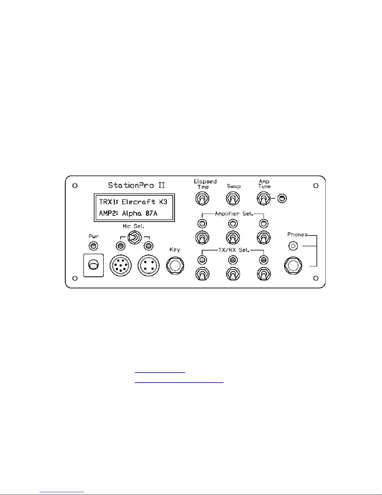
III. Front Panel Controls and Connectors
1. Pwr Switch: Connects +12VDC from rear panel power jack to StationPro
circuitry, through a 1A fuse. Also applies +12VDC (through a series 1000 resistor) to a
rear panel jack for controlling an optional master station AC power relay.

6
2.Mic Sel. Switch: Switches between two front panel microphones. Each
microphone can have up to 7 audio/control wires. The Mic+ and PTT are independently
switched but the other wires (Mic-, FCN1, etc.) are common to both microphones. As
shown in the drawing, the microphones can have different connector types. Instructions
for wiring the microphone jacks are given in the next section: B. Assembly
Instructions.
3. Key Jack: A key or paddle is connected to this standard 1/4” stereo jack, with
normally open contacts. Keyer paddles should be wired so that the plug tip = dot, and the
plug ring = dash. For convenience, an identical key jack on the rear panel is wired in
parallel with this jack.
4. TX/RX Sel. Switches (3): Depressing one of these momentary action switches
selects a station transceiver or receiver/transmitter pair.
5. Amplifier Sel. Switches (3): Depressing one of these momentary action
switches selects a linear amplifier. Pressing a switch a second time toggles the selected
amplifier off-line, as indicated by a blinking LED and “Amp Bypass” on the LCD.
6. Elapsed Time Switch: This switch has three timer functions: (1) Depressing it
momentarily starts a one-time 10min ID time. (2) Depressing it for 1/2 sec starts a
repeating 10 min. ID timer. (3) Depressing it while turning on the Pwr switch causes an
elapsed time “odometer” to display on the LCD.
7. Swap Switch: This “scratchpad” memory switch recalls the previous
transceiver and amplifier selections. Repeatedly pressing the switch toggles back and
forth between the current transceiver/amplifier selections and the previous selections.
8. Amp Tune Switch: Depressing this momentary action switch injects a pulsed
(50% duty cycle) 1000 Hz tone into the microphone audio circuit of the selected
transceiver. Pressing the switch again turns off the tone, which otherwise will time out
after ten seconds.
9. Phones jacks (2): Twin stereo headphone jacks can accommodate either 1/4 in.
or 3.5 mm (1/8”) stereo headphones (Left = tip, Right = ring). These jacks are connected
to the left/mainRX and right/subRX speaker outputs of the selected transceiver; plugging
in a set of headphones automatically disables the speakers.
7
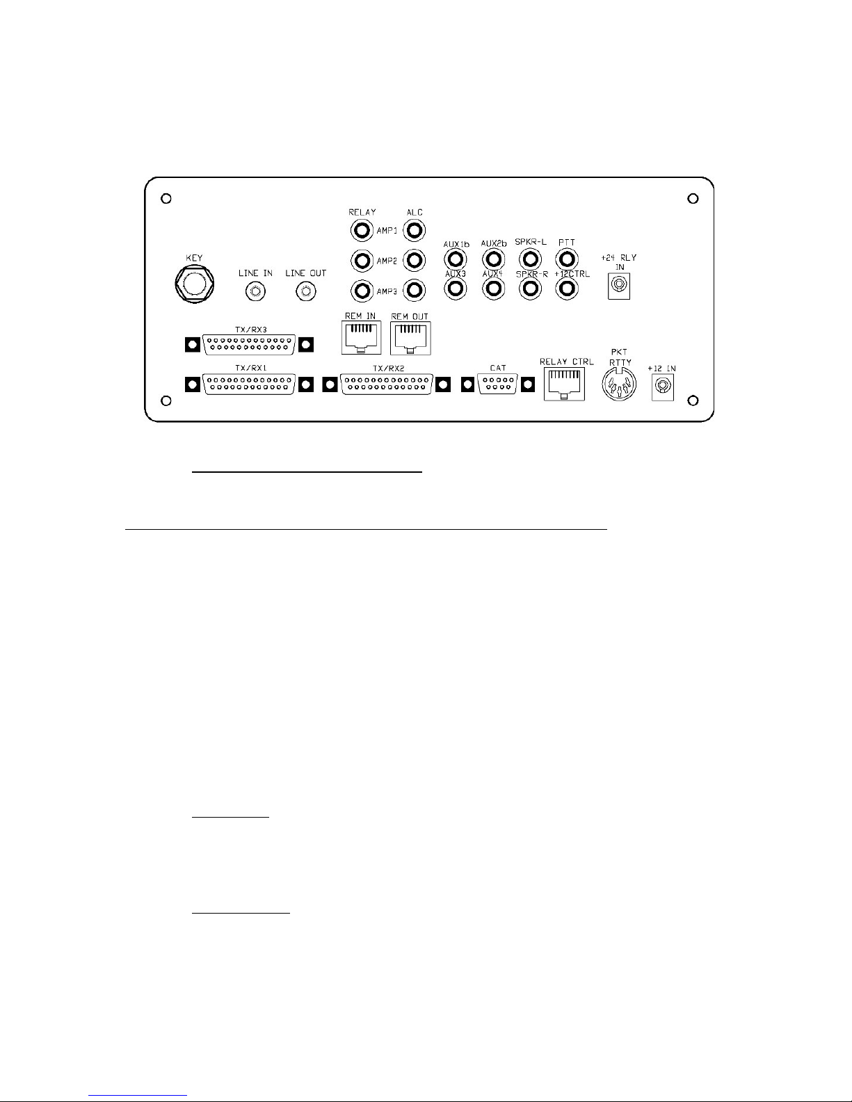
IV. Rear Panel Connections
1. TX/RX1, TX/RX2, TX/RX3 jacks: D-SUB 25-pin male jacks that connect via
breakout “pods” to the station transceivers. The pinouts of these jacks are as follows:
Pin No. Function Pin No. Function
1 Mic +
2 PTT
3 Mic -
4 Mic FN1
5 Mic FN2
6 Mic FN3
7 Mic FN4
8 Key - Ring
9 Key - Tip
10 Line Out - L
11 Line Out -R
12 Spkr - L
14 Amp Relay
15 Amp ALC
16 Aux/Spare 2
17 Aux/Spare 1
18 Aux/Spare 4
19 Aux/Spare 3
20 Line IN
21 CAT - CTS
22 CAT - TXD
23 CAT - RTS
24 CAT - RXD
25 GND
13 Spkr - R
2. KEY Jack: A key or paddle can be connected to this standard 1/4” stereo jack,
with normally open contacts. Keyer paddles should be wired so that the plug’s tip = dot,
and the plug’s ring = dash. An identical key jack on the front panel is wired in parallel
with this jack.
3. LINE IN Jack: This 3.5 mm (1/8”) mono jack is typically connected to the
output from a computer sound card or a TNC. The connected device is routed by the
StationPro to the Line In port of the selected transceiver.

8
4. LINE OUT Jack: This 3.5 mm. (1/8”) stereo jack outputs the Line Out port of a
selected transceiver. Normally, the tip would be the left or main receiver line output and
the ring would be the right or sub-receiver output. The jack is typically used to interface
a transceiver’s line output to the input of a computer sound card or TNC.
5. AMP RELAY (3) and AMP ALC (3) jacks: These RCA phono jacks should be
jumpered (use shielded phono cables ) to the relay and ALC jacks of the station’s linear
amplifiers. Because the Amp Relay outputs are buffered by a solid state switching circuit,
the user need not fear compatibility problems between a selected amplifier and
transceiver.
6. AUX1 through AUX4 Jacks: These RCA phono jacks are spares that can be
used for any control purpose by the user. The StationPro routes these jacks to spare pads
on the breakout pod associated with a selected transceiver. They can be used for, e.g.,
band data switching.
7. SPKR-L and SPKR-R Jacks: The station’s speakers should be connected to
these RCA phono jacks and are routed by the StationPro to the speaker output ports of a
selected transceiver. Normally SPKR-L would be used for the main receiver’s speaker
and SPKR-R for the sub-receiver’s speaker. These jacks are disconnected when
headphones are inserted into a front panel jack on the StationPro.
8. PTT Jack: This RCA phono jack is wired in parallel with the PTT line on the
microphone and also with pin 3 of the Packet/RTTY jack. Grounding this line actuates
the PTT circuit of the selected transceiver. A typical use would be to connect a foot
switch to this jack. Note that some transceivers ground their PTT line when transmitting,
so that this jack could be used in this instance for, e.g., external receiver muting.
9. +12 CTRL Jack: This RCA phono jack outputs +12VDC when the StationPro’s
power switch is turned on. The +12V is in series with a 1000 resistor, which limits the
short circuit current to 12 mA. Because of the series resistor, the jack cannot be used to
power 12V accessories. This switched jack is intended to control a (user-supplied) solid
state AC power relay, which can be used as a master station power ON/OFF relay. Below
is a sample circuit diagram using an SPST solid state AC relay. Any solid state relay that
operates with a DC control control voltage of 3-15V (or more) can be used. The relay
should have a load current rating of at least 25A. A DPST solid state relay can be used if
the builder wishes to switch both sides of the 120VAC line.
A convenient way to make this relay master power controller is to mount the solid
state relay in the bottom of a deep duplex outlet box, available at Home Depot or any
electrical supply store. An ordinary duplex outlet (two 120VAC receptacles) is mounted
on the face of the box, and a heavy duty AC power cord exits through one of the side
holes. A fuse holder and an RCA phono jack mount on the other side of the outlet box. A
shielded phono cable connects this phono jack to the 12V SWITCHED jack on the rear
panel of the StationPro, and an outlet strip for the station equipment plugs into one of the
two duplex receptacles. The other duplex receptacle can be wired directly to the 120V
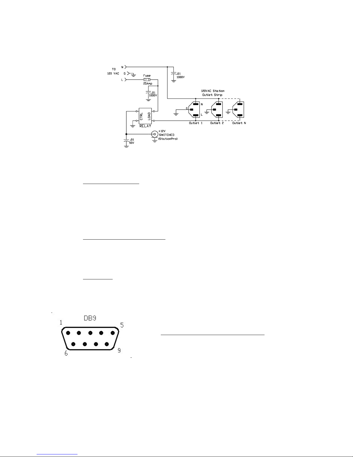
9
line, to provide an unswitched 120VAC outlet for station clocks, computer, UPS supply,
etc.
MASTER STATION 120 VAC POWER CONTROLLER
(Note that the .01 µF/1000V bypass capacitors should be 240 VAC line-rated)
10. +24V RLY IN Jack: This 2.5mm DC power jack may be used to connect an
external DC power supply (+15V to +30V) to user-supplied external RF relays. This jack
is not used with the standard RF Relay unit. Some users, however, may prefer to build
their own RF relay units using, e.g., surplus vacuum relays, which typically operate at 2428V. In this case, the StationPro will automatically connect the relays to this external
power source.
11 REM IN & REM OUT Jacks: These RJ-25 jacks are used only when multiple
StationPro IIs (up to a maximum of three) are networked together. Download the
“StationPro II Networking Manual” for additional information. Users who have only one
StationPro II can ignore these jacks.
12. CAT Jack: This female D-SUB 9 pin (DB9) connector is configured as a
standard serial port and should be connected to a serial port on a computer or other
peripheral equipment. The required cable is an ordinary 9-pin serial cable having male
and female DB9 connectors. The StationPro routes this port to the selected transceiver.
The (industry standard) pinout of this connector is as follows:
DB9 CAT Connector
Pin No. . Function
1 N/C
2 RXD
3 TXD
4 N/C
5 GND
6 N/C
7 RTS
8 CTS
9 N/C
10
13. RELAY CTRL Jack: This RJ45 jack is used to control the StationPro’s
remote RF relays. The jack accepts a standard 8-wire ethernet-type patch cable (with
RJ45 connectors). The cable should be no longer than necessary (5 – 6 ft or shorter), and
preferably shielded. The free end of the cable plugs into a mating connector on the RF
relay unit. Builders of custom RF relay units should refer to the StationPro schematic
diagram for the connector pinout,
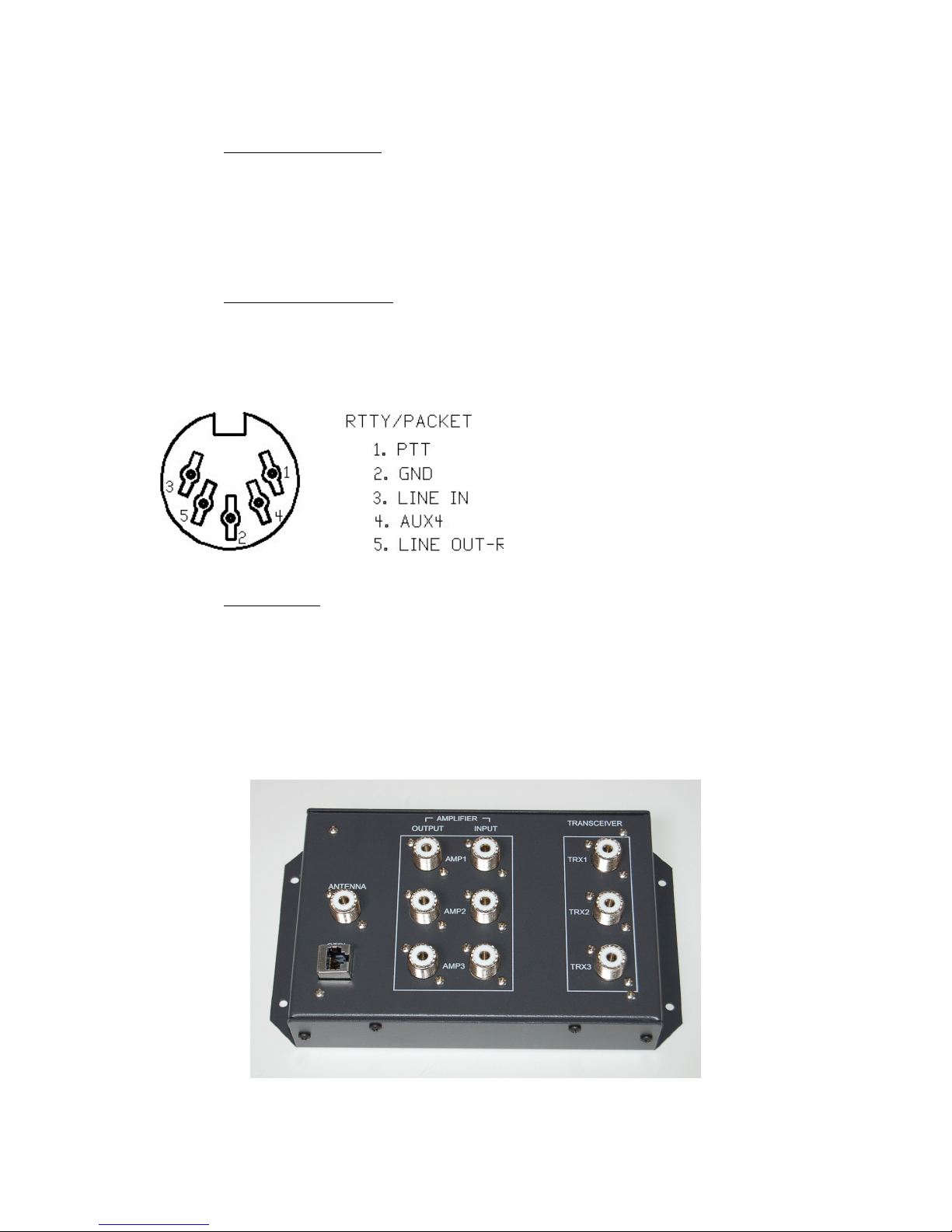
14. PACKET/RTTY Jack: This standard 5 pin DIN jack is used to connect
RTTY, Packet, and PSK31 peripherals to the StationPro. The pinout is shown in the
diagram. Note that all of the pins on this jack are in parallel with similarly named pins on
other jacks on the StationPro. The AUX4 pin is not designated for any specific purpose,
but may be configured by the user for an additional function (e.g., squelch, etc.)
15. +12 IN Jack: This DC power jack accepts a standard 2.5 mm DC power plug
(center pin positive), which should be connected to a +12V (nominal) regulated DC
power supply. This power supply can be a station +12V supply used to power other
equipment (e.g., a VHF/UHF FM transceiver), the accessory +12V port on the rear panel
of most transceivers, or even a dedicated wall-wart supply. The power supply should be
rated at 500 mA or greater and have good filtering..
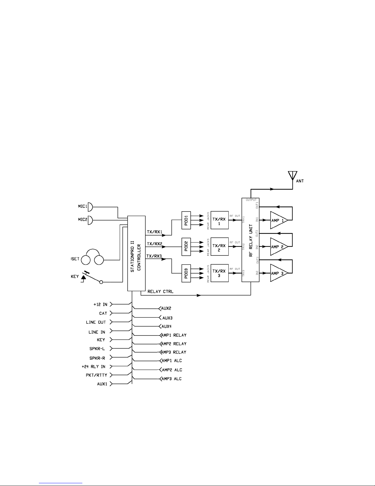
V. RF Relay Unit Connections:

11
1. TRX1, TRX2, TRX3 Jacks: These SO-239 (UHF) coaxial cable jacls should be
connected to the antenna jacks on the station transceivers, using 50 coaxial cable.
Because most transceivers are rated at 200W RF or less, RG-58 or RG8X cable can be
useds for these jumper cables. Note that the StationPro grounds the antenna connectors of
transceivers that are not selected.
2. AMP IN (AMP1, AMP2, AMP3) Jacks: These SO-239 (UHF) coaxial cable
jacks should be connected to the RF Input jacks on the station linear amplifiers, using 50
coaxial cable. RG-58 or RG8X cable can be used for these jumper cables. Note that
the StationPro grounds the inputs of amplifiers that are not selected.
3. AMP OUT (AMP1, AMP2, AMP3) Jacks: These SO-239 (UHF) coaxial cable
jacks should be connected to the RF Output jacks on the station linear amplifiers, using
50 coaxial cable. For legal limit amplifiers, it is best to use RG-8, RG-213, LMR-400
or similar coaxial cable for these jumper cables. Note that the StationPro grounds only
the input of non-selected amplifiers. The output of non-selected amplifiers is left floating
as a precaution, even though the StationPro will not allow non-selected amplifiers to be
keyed up. Note also that a bypass relay in the StationPro RF Relay unit routes RF from
the selected transceiver directly to the OUTPUT connector when no amplifier is selected.
4. OUTPUT Jack: This SO-239 (UHF) coaxial cable jack should be jumpered to
the station antenna (or antenna switch).. The coaxial cable should be rated for the
maximum power of any of the station linear amplifiers.
5. CTRL Jack: This RJ45 jack is used to control the RF relays. The jack accepts a
standard 8-wire ethernet-type patch cable (with RJ45 connectors). The cable should be
no longer than necessary (5 – 6 ft or shorter), and preferably shielded. The free end of the
cable plugs into a mating connector on the rear panel of the StationPro Control Unit.
VI. Installation and Hookup
The StationPro II consists of a main control unit, a remote RF relay unit, and three
breakout pods for the station transceivers. Normally the RF relay unit mounts behind the
station operating desk and is connected to the main control unit by a standard 8-wire
ethernet patch cable, terminated with RJ45 connectors. This cable is readily available
from any retail store that sells computer supplies.
The three transceiver breakout pods connect to the main control unit with 25-wire
shielded computer (serial port) cables. For most applications, inexpensive off-the-shelf
computer cables can be used, the kind with molded DB25 connectors on each end (one
male, one female). However, in some applications involving computer control of multiple
transceivers operating SSB or AM, the builder may have to fabricate custom interface
cables having additional shielding. This additional shielding would prevent possible
crosstalk between the high level RS-232C data and the microphone audio. This topic is
thoroughly discussed in the supplementary manual, “Preparing Custom Transceiver
Interface Cables.” However, since wiring cables is tedious, the builder should always
12
try a commercial cable first to see if a problem occurs. Furthermore, there are several
workarounds discussed in the supplementary manual, short of fabricating custom
interface cables.
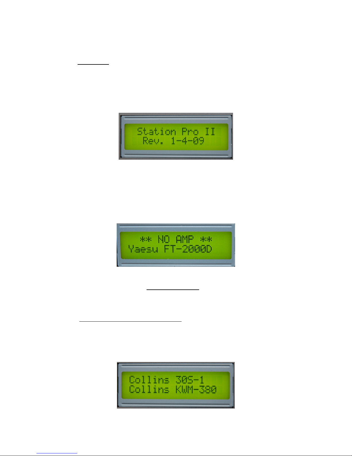
The diagram below shows how the StationPro II is interfaced to the operator’s
station. It is important to note that none of the rear panel jacks on the StationPro II
controller connect directly to transceivers. All transceiver control functions and inputs
(microphone, key, data, speakers, PTT, etc.) are made via cables coming from breakout
pods which are fabricated during assembly for each model of transceiver. The fabrication
of breakout pods is treated in detail in the next section: B. StationPro II Assembly
Instructions. The jacks on the rear panel of the StationPro II attach to the station’s
peripheral equipment, such as computer, speakers, TNC, and so forth. The StationPro II
automatically routes this peripheral equipment to the selected transceiver. Each
amplifier’s relay and ALC lines also connect to the StationPro II rear panel. Users should
refer to III. Rear Panel Connectons for details about connector pinouts.
13
VII. Operating Instructions and Hints
1. Power Up: Once the interconnecting cables are installed and a +12V DC power
source (500mA minimum) is plugged into the +12 IN jack on the rear of the StationPro II
control unit, the StationPro II can be turned on with the front panel PWR switch. The red
LED power indicator will light, and “SP” will be sent in morse code while the LCD
initializes. After about a second, the display will briefly show the firmware revision date,
followed by the previously selected transceiver.
On its initial power up the StationPro II defaults to TX/RX1. On subsequent power-ups
the StationPro II reverts to the previously selected transceiver. The bottom line of the
display shows the selected transceiver, with a confirming 3-tone beep and the sound of
relays clicking. The top line of the display will show “∗ ∗No Amp∗∗” to confirm that no
amplifier has yet been selected. (As a safety precaution, the StationPro II never selects an
amplifier at power up.)
If the user has fabricated an optional solid state relay master power controller (see III.
Rear Panel Connectors, Item 9: +12V Control Jack for details), then all the 120 VAC
station equipment will also be powered up at this time. At this point the transceiver
shown in the display will be “on-line” and ready to operate.
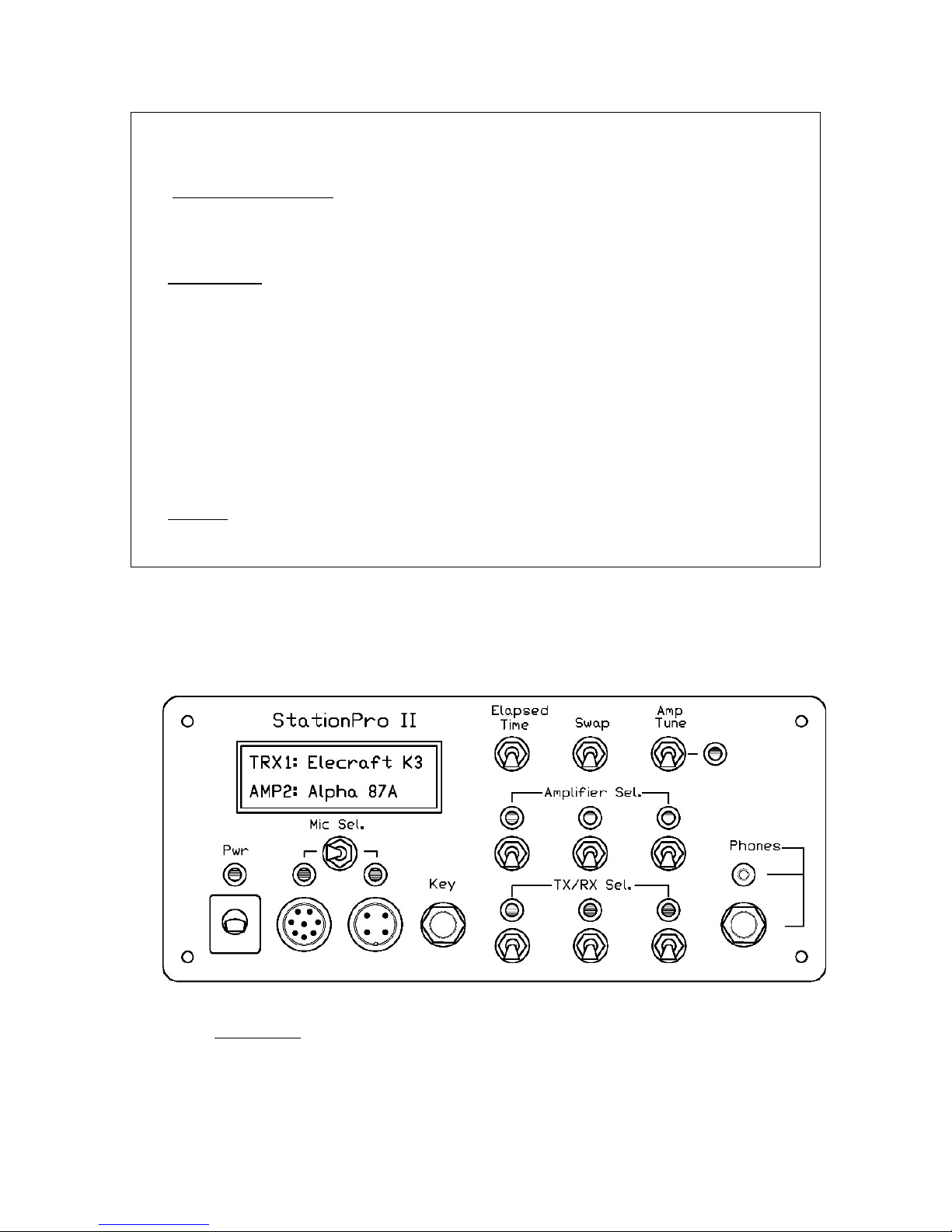
2. Transceiver and Amplifier Selection: Station transceivers and amplifiers are
selected by depressing the appropriate front panel momentary action toggle switches. A
green LED indicator will illuminate above each activated switch and the LCD will show
the selections, as illustrated in the below figure for a vintage Collins transceiver and
amplifier.
14
If the switch of a selected amplifier is depressed a second time, the amplifier will be
taken off line and the green LED indicator will blink. The top line of the LCD will show
“BYPASS” to confirm that the amplifier is in a ready mode but is currently off-line.
Depressing the amplifier select switch a third time will bring the selected amplifier back
on line.
The SWAP switch provides a convenient way to recall previous transceiver and
amplifier selections. Pressing this switch toggles between the currently selected
transceiver/amplifier selections and the previous transceiver/amplifier selections. The
SWAP feature provides a handy way to make A-B comparisons between rigs, or to recall
instantly a prior transceiver/amplifier combination. Being able to call up completely
different rigs, automatically transferring all RF coax cables, microphone, key, etc, in a
tenth of a second is guaranteed to impress one’s ham buddies.
3. Elapsed Time Features: Momentarily depressing the Elapsed Time switch
starts a one-time ten minute timer. A beep confirms the selection, and a “∗” symbol
appears on the lower right corner of the LCD to show that the timer is running. After ten
minutes, the controller will send “ID” in morse code and the timer will turn off. If the
Elapsed Time switch is held down for a half second, then a repeating timer is activated.
In this case the LCD will show a “#” symbol in the lower right corner, and the controller
will send “ID” in morse code every ten minutes, until cancelled. An active timer is
cancelled by pressing the Elapsed Time switch, with “K” being sent in morse code to
confirm the cancellation.
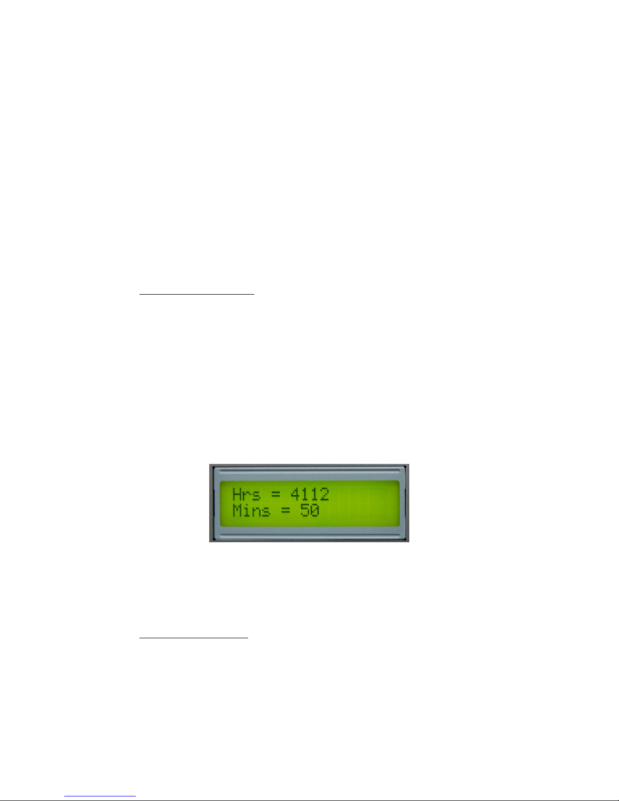
If the Elapsed Time switch is held down while the StationPro II is powered up,
then the LCD will briefly show the number of accumulated hours and minutes of
StationPro II use.
One application of this feature is to track the yearly hours of station operation. For
example, the operator can reset the timer to zero on January 1, and twelve months later
have a record of total station activity for the year. The timer is reset to zero by turning on
the StationPro II while holding down the AMP1 switch.
4. AMP TUNE function: Momentarily pressing the AMP TUNE switch injects a
pulsed 1000 Hz tone for ten seconds into the microphone input of the selected
transceiver. The purpose of this pulsed tone, which has a 50% duty cycle, is to permit the
operator to tune up safely a selected linear amplifier without fear of exceeding the
amplifier’s power rating. The plate current, grid current, and power output meters of the
amplifer, which read average values, will show roughly half of their normal values while
the pulser is engaged. While the pulsed tone is active, an LED indicator next to the AMP

15
TUNE switch blinks rapidly and the TRX and AMP LEDs are turned off. Depressing the
AMP TUNE switch before the pulser times out immediately terminates the pulsed tone.
A tune level trimpot on the microcontroller circuit board in the StationPro II
control unit sets the appropriate audio level for the pulsed tone. The correct procedure is
to place the selected transceiver in the SSB mode and turn on the pulser. The level
trimpot is adjusted to give a mid-scale ALC reading on the transceiver’s ALC meter.
5. Networking Multiple StationPro IIs: Up to three StationPro IIs may be
networked, permitting a total of nine transceivers and nine amplifiers to be controlled
(three on each operating desk). Selecting any of the nine rigs will transfer control to that
rig while taking the other eight rigs off-line. The antenna coax line is automatically
transferred to the selected radio, and the key, microphone, speakers, etc., on the relevant
station desk are transferred to the selected radio. The StationPro IIs on the other desks are
deselected and their status is displayed on their respective LCDs.
Pressing any transceiver or amplifer switch on an “off line” desk will activate that
StationPro II and take off line the previously active StationPro II.
There are additional considerations associated with networking multiple
StationPro IIs. Because this topic will be of interest to only a small number of amateurs
having very complex stations, the details of configuring networked controllers are to be
found in a separate maual: Networking StationPro II Configuration Manual.
VIII. A Final Comment from W8ZR
The philosophy underlying the design of the StationPro II is that an initial
investment made in planning and organizing one’s station will pay handsome dividends
in convenience, time savings, and operating pleasure. The ability instantly and reliably to
switch between rigs means that that more time can be spent on the air enjoying the
hobby, and fewer frustrating hours spent crouched behind the operating desk, debugging
dead connections and miswired cables, and worrying about inadvertently throwing the
wrong switch. The StationPro II and its little brother, the StationPro I, have brought for
their designer a new enjoyment and satisfaction to amateur radio. It is sincerely hoped
that other builders will experience this same enjoyment and satisfaction.
Comments, inqiries, and suggestions either about this manual or the StationPro II are
always welcome. Please email Jim Garland W8ZR at w8zr@arrl.net. A great deal of
additional information may also be found on the designer’s StationPro website at
www.w8zr.net/stationpro/ and on the StationPro User Group
http://groups.yahoo.com/group/stationpro/

16
Assembly
Hints
B. StationPro II Assembly Instructions
The W8ZR StationPro II (SP-II) consists of the primary controller unit, plus an external
RF relay unit, and three transceiver interface pods that attach to the controller unit with standard
computer cables. The controller unit contains four printed circuit boards: (1) a main circuit
board, (2) a front panel circuit board, (3) a rear panel circuit board, and (4) a microcontroller
circuit board.
The RF relay unit handles all of the RF switching for the user’s transceivers and
amplifiers. The transceiver “pods” are simple breakout boxes that interface to each connected
transceiver (or receiver/transmitter pair). Builders should allow about 14-16 hours to wire and
test a complete SP-II. You’ll maintain focus and avoid mistakes if you break up the work into
segments.
Note: If you received this manual with your W8ZR kit, then please verify
that the revision date on the Contents page corresponds to the revision date
of the manual at www.w8zr.net/stationpro/download. The W8ZR website
will always have the latest revision number for all documentation and
firmware.
I. Preparation for Assembly
(1) Tools: To build the StationPro II you will need the following tools and small items:
-hookup wire #22AWG, 50ft approx
-small tip soldering iron
-1/32” diameter resin core solder
-isopropyl (rubbing) alcohol & Q-tips
-magnifying glass
-small needle-nose pliers
-small flush-cut wire cutters
-phillips screw drivers (small & medium)
-small flat head screwdriver
-sharp knife or single-edge razor blade
-3/16 in. drill bit (5 mm approx.)
-small flat and round files (optional)
-set of nut drivers (optional)
-regular tip soldering iron (optional)
-1/4 in. heat shrink tubing (optional)
-transceiver cables (see Sec. X)
(2) Hardware: The hardware to assemble your
SP-II is supplied in two hardware packs with the
W8ZR “semi-kits.”
1. Make sure your workbench surface is
clean and free of clutter.
3. Inventory and sort parts and read
through the assembly nstructions before
you begin construction. Read the FAQs
page on the W8ZR StationPro website.
2. Use a high-intensity light and magnifying
glass to inspect your solder joints and to
look for solder bridges.
4. To give your work a professional
appearance, install resistors and capacitors
so their color codes and markings all face
the same way.
5. Work carefully and methodically and take
your time. Take pride in your workmanship,
and if you complete a step and it doesn’t
look good, then do it over.
17
Note: additional cabinet hardware is packed with the enclosure for the SP-II control unit.
Threaded aluminum standoffs are supplied by Mouser Electronics as part of your component
order.
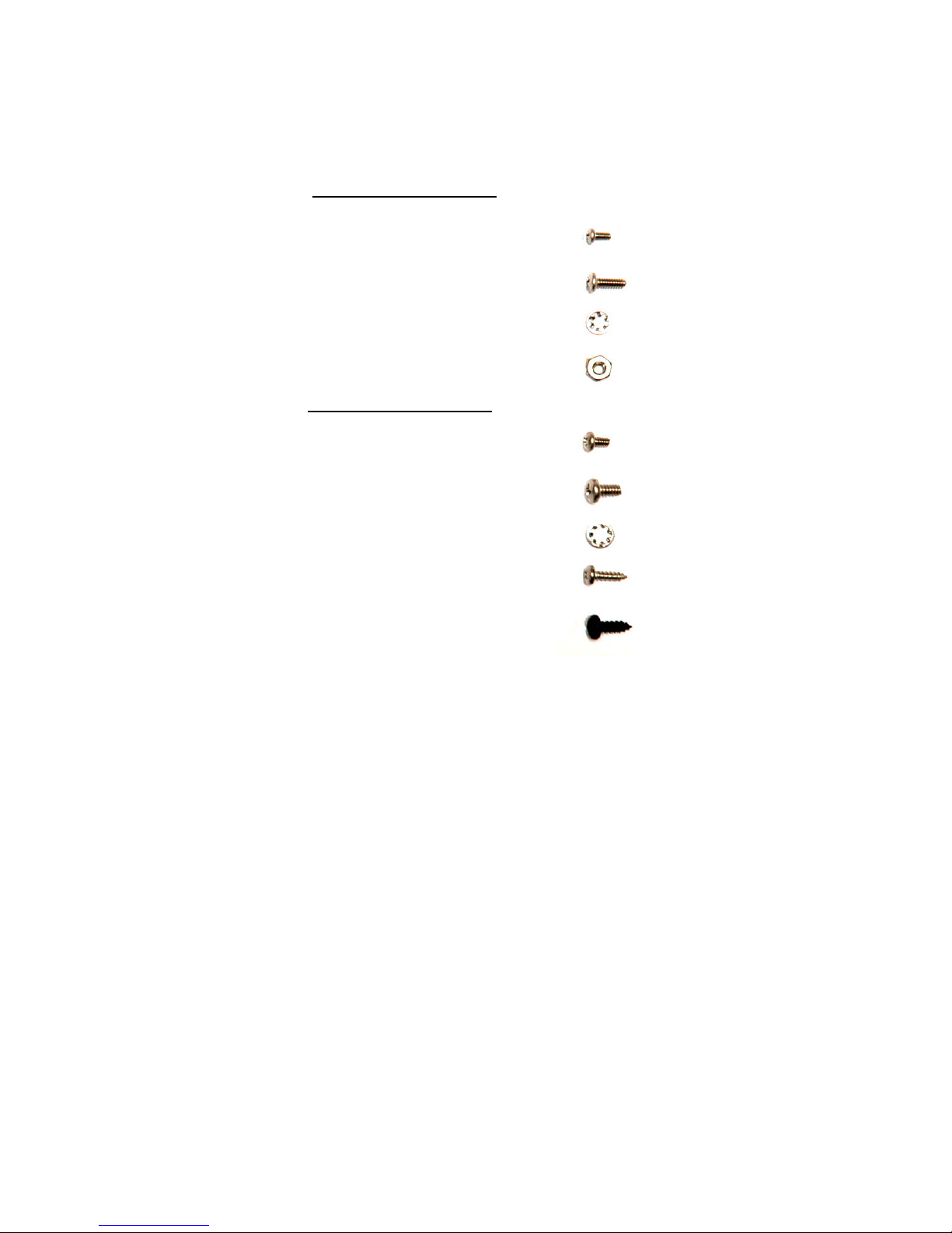
HARDWARE PACK 1
Qty 8 2-56 x 3/16” screws
Qty 20 4-40 x 5/16” screws
Qty 28 No. 4 internal lockwashers
Qty 20 4-40 nuts
HARDWARE PACK 2
Qty 8 4-40 x 3/16” screws
Qty 8 6-32 x 1/4” screws
Qty 8 No. 6 internal lockwashers
Qty 18 No. 4 x 3/8” sht. metal screws
Qty 8 Black No. 6 x 3/8” sht. metal screws
II. Microphone Jack Considerations
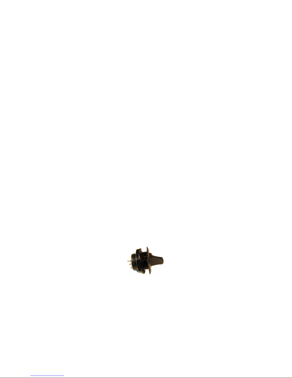
Two 8-pin mic chassis jacks are included with your “semi-kit,” and most modern
transceivers (Kenwood, late Ten-Tec, Icom, Yaesu, Elecraft, Flex-Radio) will use these
jacks. Older vintage rigs (earlyTen-Tec, Drake TR-5/7, Johnson Ranger, Collins KWS-1,
Heathkit, etc.) typically used either 4-pin or 2-pin connectors. The mic jacks for all of
these vintage rigs also will fit in the 5/8 in. prepunched holes in the front panel, but must
be supplied by the builder.
Some other vintage rigs, for example the Collins “S-Line”, the Drake “B-Line”
and “C-Line,” and the National NCX-5, use 3/16 in. or 1/4 in. microphone plugs whose
mating jacks require a 3/8 in. hole. If you want to use one of these microphone jacks, then
you should use insulating washers (not supplied) to adapt each jack to the 5/8 in. hole in
the StationPro’s front panel. (Insulating washers will minimize hum pickup – see the next
paragraph and Appendix A: Avoiding Ground Loop Complications.)
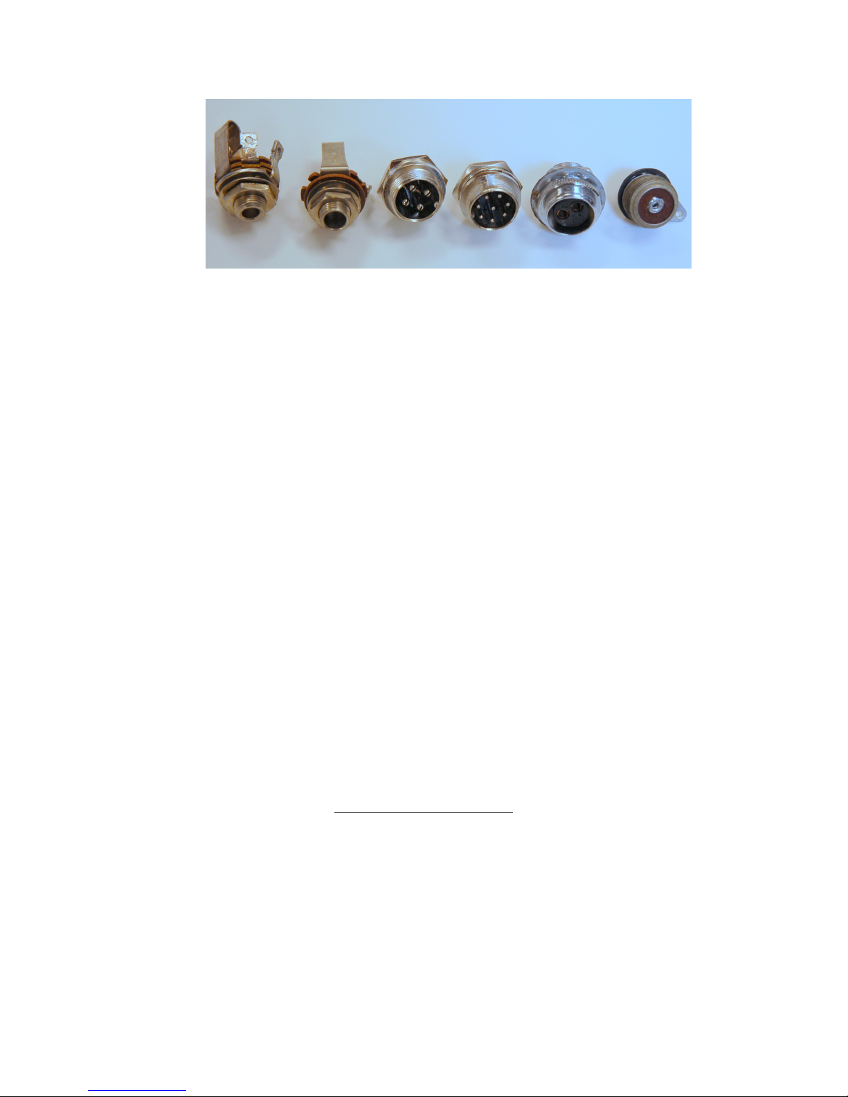
18
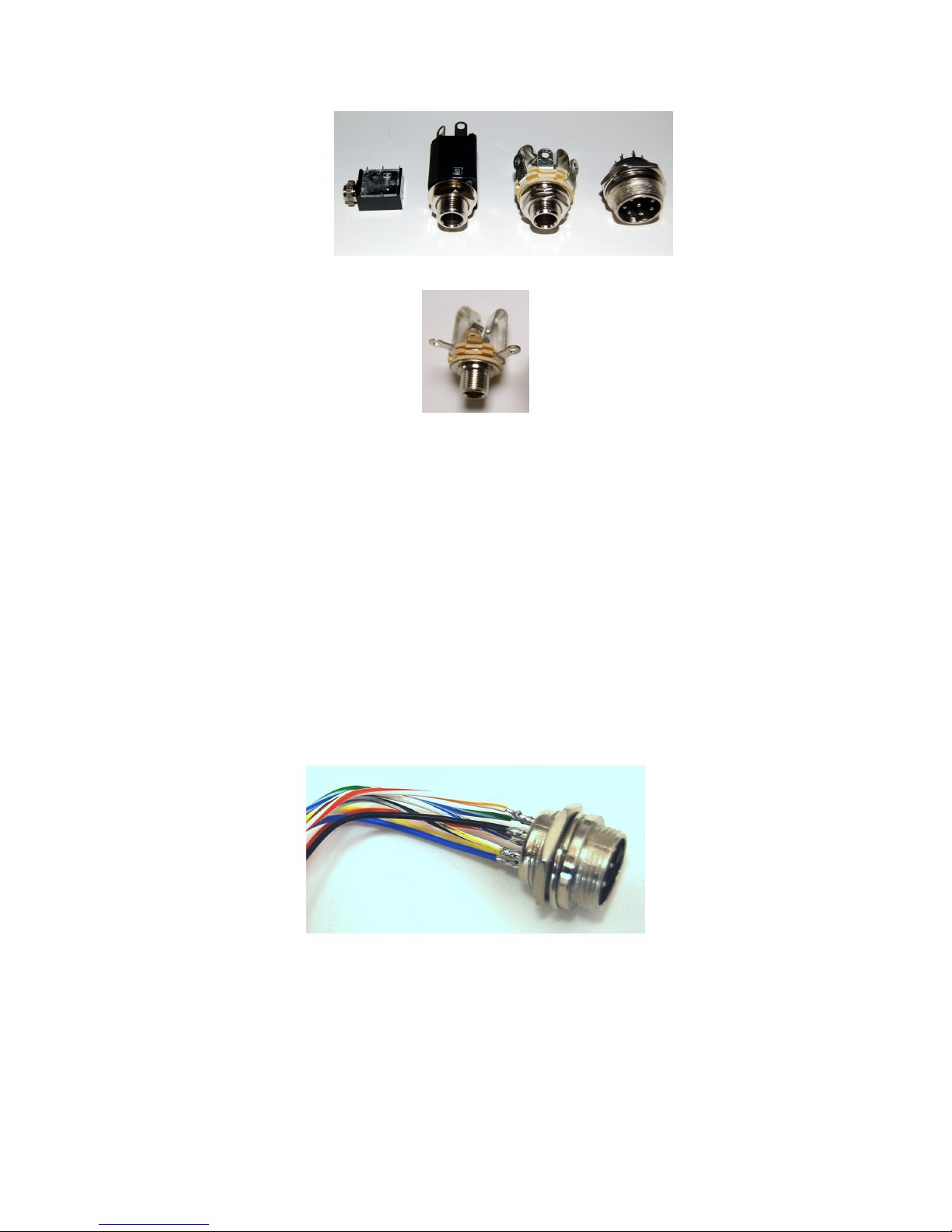
Any of these microphone jacks can be used with the StationPro, although the two on the left
will require washers to clamp them to the 5/8” hole in the front panel
You can “mix and match” microphone jacks in the StationPro, e.g., using one 8pin and one 4-pin jack. Also, you can easily configure the SP-II so that a microphone
wired for, say, a forty-year-old Collins KWM-2 transceiver, can be used with a modern
Elecraft K3 transceiver, even though the mic connectors are different. Note, however,
that vintage microphones using a single shielded cable to carry audio signals (as opposed
to modern microphones having dedicated mic+ and mic- conductors) are particularly
susceptable to hum caused by ground loop currents. Before installing jacks intended for
such microphones (such as the 2-pin 5/8 in. jack – second from the right in the above
photo), you should carefully read Appendix A: Avoiding Ground Loop Complications
at the end of this manual
III. Front Panel Assembly
The front panel is the most complex part of the entire assembly process, so we
will get it out of the way first. Begin by reading through these instructions. Then identify
the front panel circuit board and, referring to the parts listing shown below, collect all of
the components. (Additional information about each component is in Appendix B: SP-II
Parts List, at the end of this manual. Also, photos of most components are shown in the
step-by-step directions that follow.) Note that components mount on both the front and
rear sides of the front panel circuit board, as indicated by the white silkscreened legends.
Also note that Header H302 is unused, even though its outline is shown on the circuit
board
SPII Front Panel Parts List
IC socket 18 pin DIP 18 pin IC socket
C301-C307 1000 pF Capacitor, 50V, epoxy-dipped ceramic, qty 7
C308, C309 47 pF Capacitor, 50V, epoxy-dipped ceramic, qty 2
C310
0.1 µF Capacitor, 50V, epoxy dipped ceramic, qty 1
C311 1 µF Capacitor, electrolytic, 50V, qty 1
DS301-DS304,
DS308, DS309 LED LED, Green, qty 6
DS306-DS307 LED LED, Yellow, qty 2
19
DS305, DS310 LED LED, Red,, qty 2
-- LED bezels LED mounting clips, qty 10
J301 Key Jack 1/4 in. Stereo NO Phone Jack, qty 1
J302 Phone Jack 1/4 in. Stereo NO/NC Phone Jack, qty 1
J303 Phone Jack 3.5 mm Stereo NO/NC Phone Jack, qty 1
P305 Header 40 pin, 0.100 male, breakaway header, qty 1
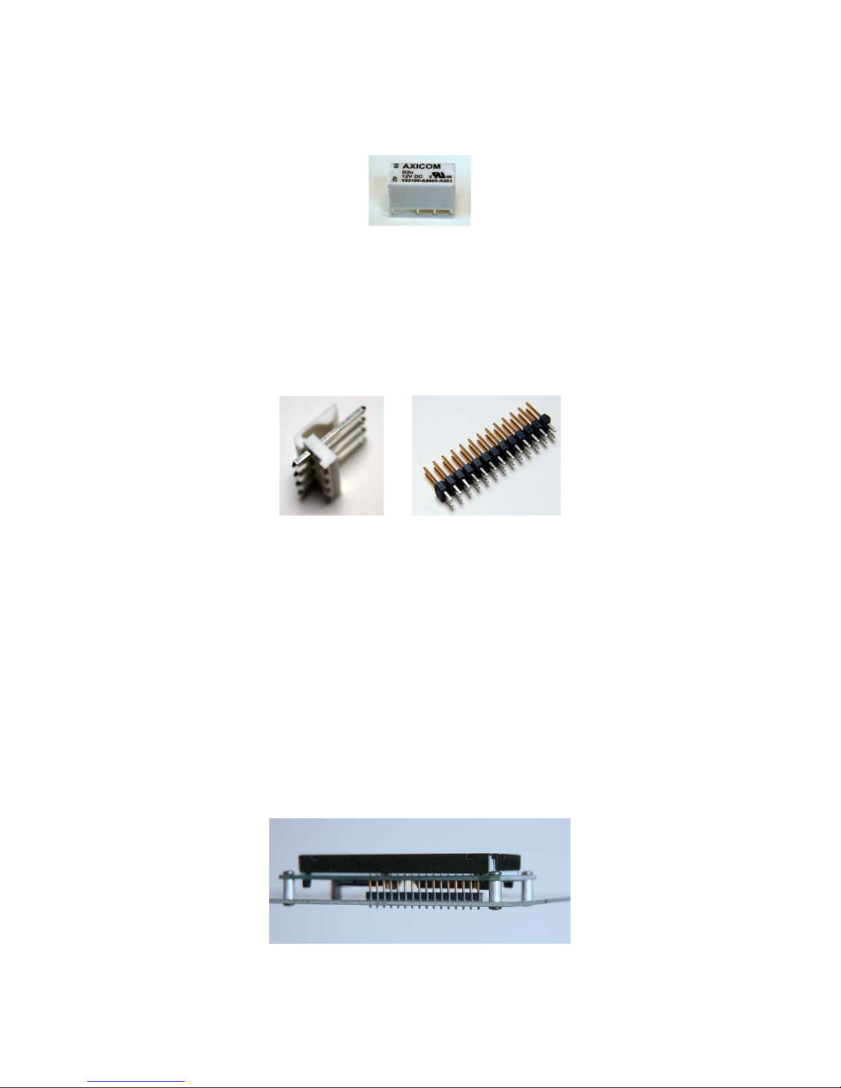
K301 Relay P&B/Tyco V23105, DPDT 12VDC, qty 1
P301, P307 Header Molex, 26-pin (2x13), 0.100 male header, qty 2
P302 Header Molex 4-pin 0.156” PCB connector w/locking clip, qty 1
LCD 16x2 LCD Microtips 16x2 LCD
R301 5 KΩ trimpot carbon trimmer potentiometer
R302-R304 2.2 KΩ Resistor, 5% carbon film 1/4W (red-red-red), qty 3
R305-R311 1000 Ω Resistor, 5% carbon film 1/4W (brown-black-red), qty 7
R312 22 KΩ Resistor, 5% carbon film 1/4W (red-red-orange), qty 1
R313 220 KΩ Resistor, 5% carbon film 1/4W (red-red-yellow), qty 1
R314 4.7 KΩ Resistor, 5% carbon film 1/4W (yellow-violet-orange), qty 1
R315, R317, R318 10 KΩ Resistor, 5% carbon film 1/4W (brown-black-orange), qty 3
R316 10 Ω Resistor, 5% carbon film 1/4W (brown-black-black), qty 1
S301 Switch Plastic DPDT paddle, qty 1
S302 Switch Min. toggle, flat lever SPDT, qty 1
S303-S311 Switch Min. toggle, flat lever SPDT mom. action, qty 9
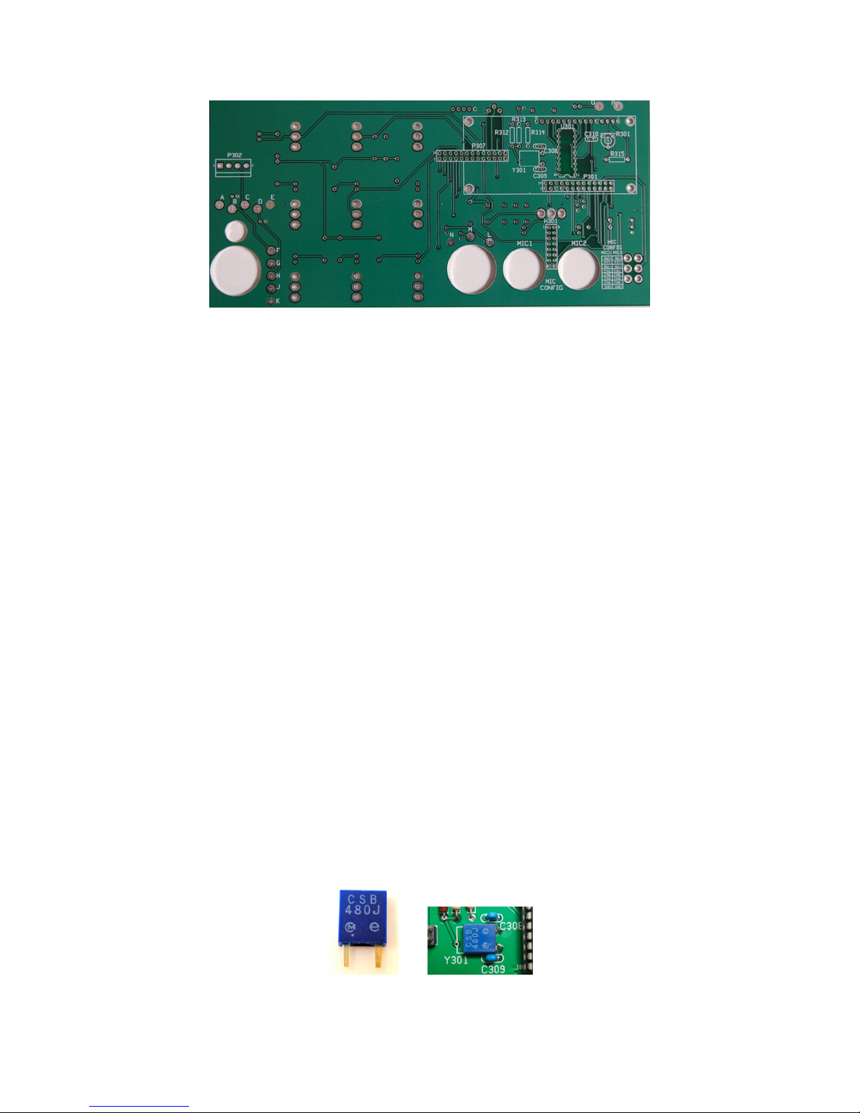
Y301 Ceram. Res. 480 KHz ceramic resonator
U301 IC PIC16C54 custom pre-programmed IC
---- connectors 8 pin mic jacks, qty 2
---- hardware threaded standoff, round alum., 2-56 x 1/4,” qty 4
---- hardware 2-56 x 3/16” machine screws, qty 8
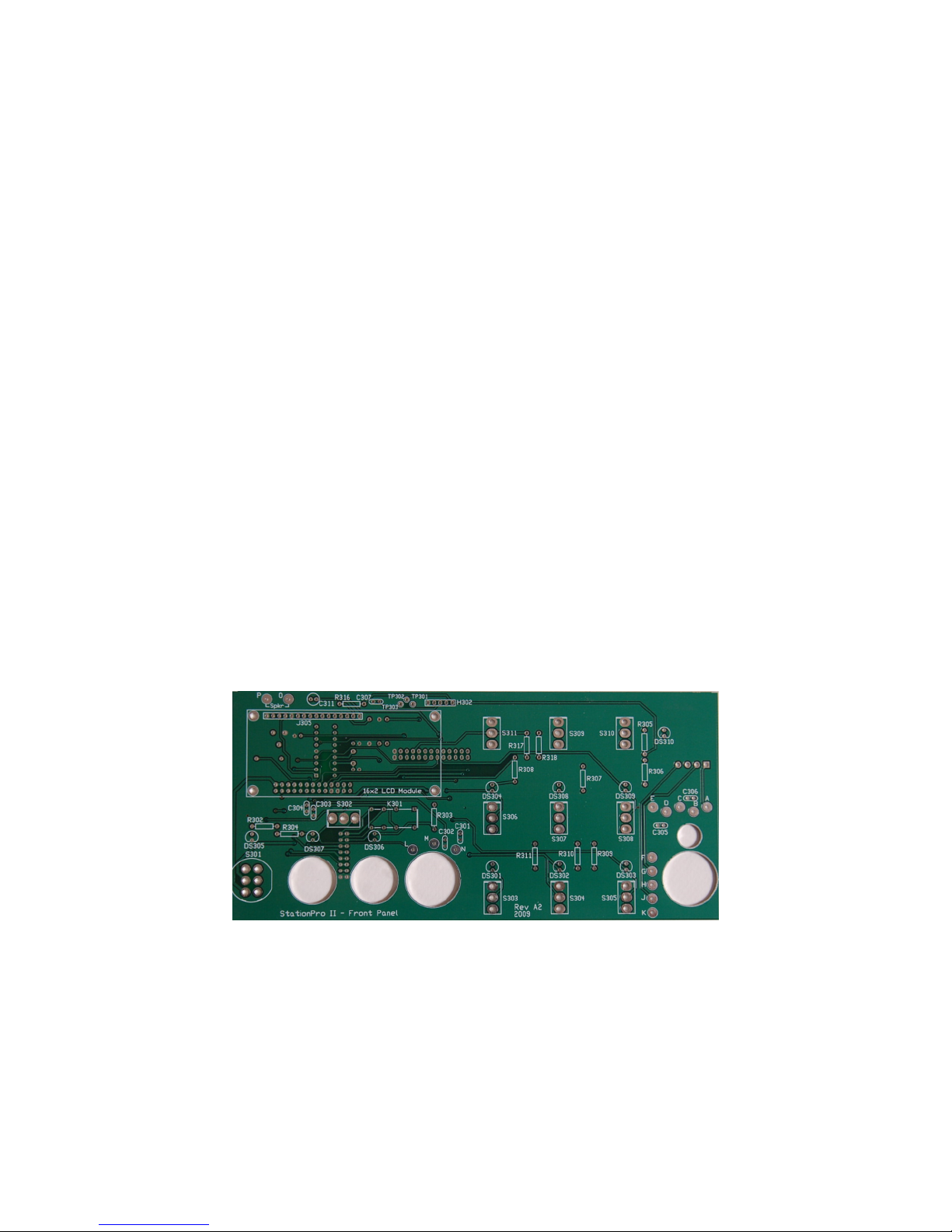
Front Panel Circuit Board –Front View
20
Front Panel Circuit Board – Rear View
(1) Install the following 1/4 Watt metal film resistors and the 5 KΩ trimpot onto the
circuit board. Note that some resistors mount on the rear side of the board, as indicated on
the silkscreening. Make certain the resistor bodies lie flat against the board before
soldering and align all the resistor color codes in the same direction.
R302-R304 2.2 KΩ (red-red-red)
R305-R311 1000 Ω (brown-black-red)
R312 22 KΩ (red-red-orange)
R313 220 KΩ (red-red-yellow)
R314 4.7 KΩ (yellow-violet-red)
R315,R317,R318 10 KΩ (brown-black-orange)
R316 10 Ω (brown-black-black)
R301 5 KΩ Trimpot
(2) Install the following ten blue epoxy-dipped capacitors and one electrolytic capacitor
onto the circuit board. Make sure you install the capacitors on the front or rear side, as
indicated by the silkscreening, and that you observe the polarity of the electolytic
capacitor.
C301-C307 1000 pF (marked 102 – blue epoxy-dipped)
C308, C309 47 pF (marked 470 – blue epoxy-dipped)
C310 0.1 µF (marked 104 – blue epoxy-dipped)
C311 1.0 µF electrolytic (observe polarity when installing)
(3) Install the 480 kHz ceramic resonator Y301 on the rear side of the circuit board. Bend
the two tabs down, as shown below, so the resonator lies flat against the outline on the
circuit board.
21
(4) Install relay K301 on the front side of the board. Make certain the relay body lies flat
against the board. Hint: solder diagonally opposite pins first, so you can readjust the
relay body if necessary.
(5) Install the 18 pin DIP IC socket at U301 on the rear side of the circuit board. Make
sure the notch on the socket is aligned with the notch on the silkscreening. Do not plug in
the IC yet.
(6) Install two 26-pin headers at P301, P307 and the 4-pin 0.156” PCB connector
w/locking clip at P302 on the rear side of the circuit board. Hint: solder the end pins first
to secure the headers. Then, after you’re certain the headers are seated against the
board, with the pins perpendicular to the board, solder the remaining pins.
(7) Mount the LCD to the front panel, as follows: (Note: the rectangular cutout on the
front panel is sized for the recommended Microtips NC-S16205DFYSAY display. If
other brands of LCDs are used, it may be necessary to file slightly the cutout opening.)
(a) Slide a 16-pin 0.100” header into position J305 on the front side
of the circuit board, but do not solder it yet. (Clip the 16 pins off of a
40 pin breakaway header using wire cutters.)
(b) As shown below, loosely mount the LCD onto the top side of the
circuit board using a 1/4” x 2-56 threaded standoff and two 2-56 x
3/16” screws at each of the four mounting holes. The top of the J305
header pins should fit into the mating holes on the LCD. Do not
solder the pins yet. (You want the screws to be loose enough so you
can center the LCD in its front panel cutout in a subsequent step.
The LCD display mounts on four 1/4” threaded standoffs with 2-56 x 3/16” screws and connects to the
circuit board with the 16 pin header. Be sure to solder both ends of each header pin.
22
(8) Remove all hardware from the nine momentary action toggle switches and discard the
flat washers. Finger tighten one of the nuts against each switch body and then temporarily
secure each toggle switch to the front panel. The lockwashers should be behind the panel,
and the front panel nuts should also be only finger-tight. IMPORTANT: make certain the
bat handles are pointing upward on all the switches, so that the handles are pressed down
to actuate the switch.
(9) In the same way, temporarily mount the SPDT miniature snap-action toggle switch
S302 to the front panel. The switch mounts sideways, in either direction.
(10) DO NOT attach the plastic DPDT AC power switch to the front panel. It will be
installed later.
(11) Temporarily attach the circuit board to the front panel, adjusting the switches as
necessary to make sure their pins fit into the mating holes on the circuit board, and that
the LCD fits into the square cutout on the front panel. Use the slight bit of wiggle room
on the LCD mounting screws to center the LCD into its cutout. When you are certain the
switch bodies are snug against the circuit board, and that the LCD is flush with the front
of the panel, and after you have double-checked that no switches are mounted upside
down, then solder all the switch pins to the circuit board. Now tighten the LCD mounting
screws on the rear side of the printed circuit board
(12) Detach the front panel from the circuit board, taking care not to lose the outer nut
and lockwasher from each switch. Hint: note that the nuts on S302 are slightly smaller
than the nuts on the momentary action switches, so don’t get them mixed up. Now tighten
the top screws on the LCD spacers and solder all the pins on both ends of J305 (32 solder
connections in total).
(13) Mount the plastic DPDT AC power switch S301 on the front panel (it goes either
way). The nut should be finger tight. Now set the front panel aside.
(14) Identify all the jacks that mount on the front panel: two microphone jacks, the 1/4 in.
key jack (J301), the 1/4 in. headphone jack (J302), and the 3.5mm headphone jack
(J303). As illustrated below, bend the solder lugs out flat on the key jack, so that they
won’t touch the printed circuit board when installed. Don’t mix up the two 1/4 in. jacks;
the J302 jack has a black plastic shell.
AC Power Switch S301
23
Left to right: J303, J302, J301, 8-pin Mic
Bend the solder lugs on the key jack (J301) out flat, so they won’t touch the front panel printed circuit
board. If you’re installing your own mic jacks with exposed solder lugs, bend them out flat too.
(15) Before starting, read carefully through the following steps, especially those
pertaining to wiring the 8-pin DIN microphone jacks.The spacing between wires is very
close and it is easy to confuse the pin numbers on the 8-pin jacks. It is strongly
recommended you download “W8ZR’s Wiring Tips for Builders” from the StationPro
“Download Files” page before beginning. Solder a 5 inch length of hookup wire
(approximately) to each pin on all jacks. (You will trim to size, later.) Important: when
you solder the wires to the black 1/4 in. headphone jack (J302), orient the wires so they
emerge from the side of each terminal rather than straight out the back. (See second photo
on next page.) This will increase the rear clearance for this jack, which is tight when the
front panel is installed in the cabinet. Hint: a small length of sleeving or heat-shrink
tubing slipped over each pin of multipin mic jacks will make a neat-looking job (not
shown in below photo. This would also be a good time to read FAQ No. 11 about hookup
wire on the W8ZR StationPro website.)
Different wire colors make it easy to keep track of microphone jack pin numbers.
(16) Loosely attach all the jacks to the front panel and then secure the printed circuit
board to the front panel with the toggle switch hardware. If necessary, adjust the AC
power switch so that its pins fit into their mating circuit board holes. As before, there
should be a nut and lockwasher behind the panel for each of the miniature toggle
switches. Feed all the jack wires though the access holes in the circuit board, as shown in
the following two photos.
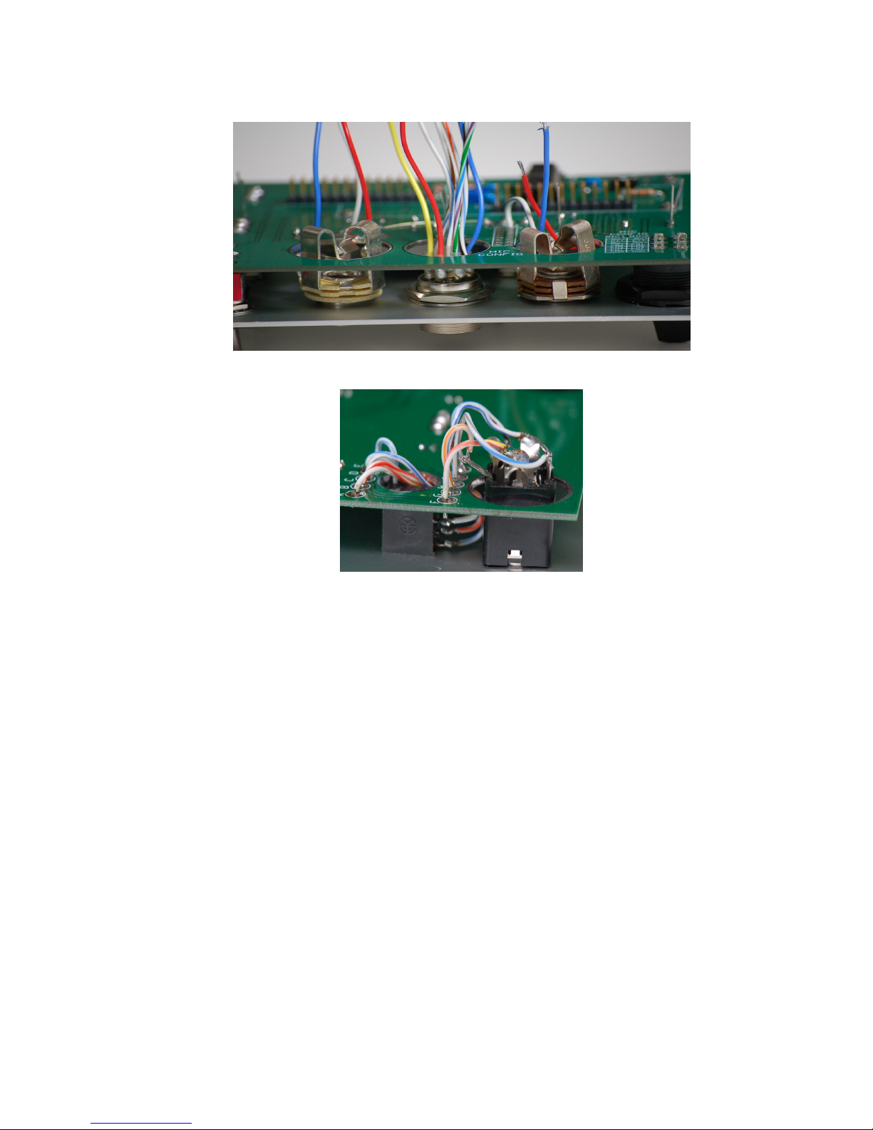
24
Detail showing wires from jacks threaded through the access holes on the
front panel printed circuit board. Be sure none of the wires interferes with
the jacks’ operation
(17) Make sure none of the jack wiring interferes with the insertion of plugs. If you have
provided your own 1/4” or 3/16” microphone jacks, be certain that their tabs do not
touch the rim of the circuit board holes. You will need to insert a plug into the jacks to
verify adequate clearance, since the plugs bend the tabs out slightly. If any tabs touch the
hole rims, then file the hole rim with a small needle file to provide clearance. (No filing
will be necessary if you use the supplied 8-pin mic jacks, or other jacks that fit the 0.625”
front panel holes.)
(18) Rotate the jacks so that their wires are oriented adjacent to the matching lettered
pads on the circuit board. The indent on 8-pin microphone jacks should face downward,
and the washer should be behind the panel. Flat washers on 1/4 in. jacks go in front of
the panel. There are no washers on the 3.5 mm headphone jack. Note that the clearance
behind the black plastic 1/4 in. headphone jack will be tight once the front panel is
installed, so do not use a second nut behind the panel on the jack. Now tighten all the
jacks to the front panel, and also tighten the plastic nut on the AC power switch. Take
care not to scratch the panel.
(19) Solder the pins on the plastic AC power switch S301 to the circuit board.
 Loading...