

Operating manual
WÄRTSILÄ
JOVYCUBE 160
BAX 5157_en

- 2 - BAX 5157 WÄRTSILÄ JOVYCUBE 160
Index Date Name Revision
0 09.03.2016 J. Schulte First edition
1
2
3
4
5
6
7
8
9
10

WÄRTSILÄ JOVYCUBE 160 BAX 5157 - 3 -
Contents
1 Introduction 5
1.1 General instructions 5
1.2 Overview of warning information 6
2 Description of the system 7
2.1 Functional description 8
2.1.1
UPS module 8
2.1.2
Static bypass module 9
2.1.3
UPS system 9
2.1.4
Battery 9
2.1.5
Internal, manual bypass 9
2.2 Operating states 10
2.2.1
Normal operation 10
2.2.2
Module error 10
2.2.3
Mains failure 11
2.2.4
Manual bypass 11
2.2.5
Smart bypass 12
3 Installation 13
3.1 Installation 13
3.2 Electrical connections, cross sections, fuses 13
3.2.1
Fuses and cross sections for cable connections to the UPS 14
3.2.2
Connections to the UPS 14
3.2.3
Mounting and connecting the battery 14
4 Operation 15
4.1 Software overview 15
4.2 Touchscreen Display 16
4.3 Controller T4S 16
4.4 Startup/Login 17
4.5 Standard functions 17
4.5.1
[1] AC Input 18
4.5.2
[2] Battery 18
4.5.3
[3] UPS Module 18
4.5.4
[4] AC Output 20
4.6 Toolbar 20
4.6.1
Events 20
4.6.2
Connections 21
4.6.3
Files 21
4.6.4
Parameters 23
5 Start-up and shutdown procedures 27
5.1 Functions of the LEDs on the module 27
5.2 Power capacity utilisation per phase 27
5.3 Operating principle of the LEDs on the SBP module 28
5.4 Start-up 29

- 4 - BAX 5157 WÄRTSILÄ JOVYCUBE 160
5.4.1
Problems during start-up 29
5.5 Shutdown 30
5.6 Start-up from the internal manual bypass 30
5.7 Shutdown to the internal manual bypass 31
5.8 Start-up of an additional 20kVA CUBE module 31
5.9 Replacing a smart bypass module 32
6 Servicing 33
6.1 Replacing a module 33
6.1.1
Removal 33
6.1.2
Erase missing module from the controller 33
6.1.3
Installation 33
6.1.4
Replacing a fan/resetting the interval 33
6.2 Maintenance 34
6.2.1
Visual inspection 34
6.2.2
Function test 34
6.2.3
Battery inspection 34
6.3 Repairs 35
6.3.1
Spare parts list 35
7 Troubleshooting 36
8 Technical data 42
8.1 20kVA CUBE module 42
8.2 Input data 42
8.3 Output data 42
8.4 Smart Bypass 43
8.5 Battery data 43
8.6 Touchscreen 43
8.7 Controller T4S 43
8.8 Ambient conditions and standards 44
9 Appendix 44

WÄRTSILÄ JOVYCUBE 160 BAX 5157 - 5 -
1 Introduction
Congratulations on purchasing a UPS unit from our WÄRTSILÄ JOVYCUBE series. The static UPS
you have chosen incorporates the latest state of technology in power electronics and digital signal
processing. It provides an ideal solution to the problems of supplying power to electronic data processing
systems.
Our JOVYCUBE UPS systems are true online systems (UPS classification VFI SS 111 in accordance
with IEC 62040-3) that protect your consumers. The production of this equipment is subject to stringent
quality assurance. As a result, the UPS offers the perfect solution to your power supply needs.
The reliability of this product is our top priority and the result of more than 65 years of experience in
secure power supply technology.
1.1 General instructions
Please read these instructions carefully
This operating manual includes safety requirements, instructions for installation as well as working
instructions to help you guarantee the maximum performance and operating readiness the UPS offers.
The manufacturer accepts no liability for damage to persons or equipment caused by non-adherence to
instructions given in this manual.
Please keep these instructions in a safe place
They contain important rules for the safe use of this UPS and information for contacting the
manufacturer's service department (see back page) in the event of any questions or problems
concerning the UPS and its correct operation.
Validity
This operating manual reflects the technical status of the UPS at the time of printing. Its contents are
not part of any contract but are for information purposes only.
Wärtsilä JOVYATLAS EUROATLAS GmbH reserves the right to make substantive and technical
changes relative to the content of this operating manual without prior notification. Wärtsilä JOVYATLAS
EUROATLAS GmbH cannot be held liable for any errors or inaccuracies in this operating manual, in
view of the fact that no obligation to provide regular updates to it exists.
Limited warranty
Our goods and services are subject to the general terms of delivery for products of the electronics
industry as well as our general sales conditions. We reserve the right to make changes to this operating
manual – in particular the technical data, operating instructions and weights and measures stipulated in
it – at any time. We ask that any claims in respect of delivered goods be submitted within eight days of
receipt of goods, enclosing the relevant packing note. Claims made at a later time cannot be considered.
Wärtsilä JOVYATLAS EUROATLAS GmbH will cancel without notice all obligations entered into by
Wärtsilä JOVYATLAS EUROATLAS GmbH and its agents, such as warranties, service agreements
etc., if replacement parts other than original Wärtsilä JOVYATLAS EUROATLAS GmbH parts or parts
purchased from Wärtsilä JOVYATLAS EUROATLAS GmbH are used in servicing and repair.
Copyright
Any disclosure, reproduction and/or copying of this operating manual, by electronic or mechanical
means, in whole or in part, requires the express prior written consent of Wärtsilä JOVYATLAS
EUROATLAS GmbH.
Copyright Wärtsilä JOVYATLAS EUROATLAS GmbH 2015. All rights reserved.
- 6 - BAX 5157 WÄRTSILÄ JOVYCUBE 160
1.2 Overview of warning information
Correct operation and servicing and adherence to the safety regulations are essential in order to protect
personnel and ensure that the system is constantly operational. All personnel involved in
installing/dismantling, start-up, operation and service of this equipment must be familiar with and
observe these safety regulations. Only trained and qualified personnel may carry out the described work
and they must use the proper, intact tools, equipment, test equipment and materials.
Important instructions are indicated by the terms "CAUTION", "ATTENTION" and "NOTE", and by
indented text passages.
CAUTION:
This symbol identifies all working and operational procedures requiring absolute
compliance to avoid any danger to personnel.
ATTENTION:
This symbol identifies all working and operational procedures requiring absolute
compliance to prevent any damage or disruption to the uninterruptible power supply (UPS)
or any of its components.
NOTE:
This symbol identifies technical requirements and additional information requiring the
operator's attention.
i

WÄRTSILÄ JOVYCUBE 160 BAX 5157 - 7 -
2 Description of the system
Ensuring a reliable power supply is one of many major issues when using electronic data processing
and process control systems. The main causes of many interruptions to power supply are:
Spikes produced by switching devices on the mains distribution
High frequency superposition caused by welding machines, fluorescent lights, photocopiers and
more
Voltage variations due to fast load variations in big inductive consumers (lifts, transformers,
machinery, etc.)
Voltage failures due to disturbances in the mains supply
Frequency variations caused by the use of separate power supply units
The range of disturbances extends from data corruption to memory leaks and from hardware failure to
production stoppages. Therefore, the quality of the power supply is key to the reliability of electronic
data processing equipment. The perfect solution for a secure, uninterrupted power supply for critical
consumers is thus the UPS (Uninterruptible Power Supply). The UPS:
Generates a constant supply voltage and frequency
Reduces mains disturbances and feedback
Guarantees an uninterruptible power supply to connected consumers for a specified period
during a mains failure
In comparison with conventional power sources such as the mains power supply or generators*, the
cutting edge technology featured in UPS systems in the JOVYCUBE series brings the following
outstanding advantages:
Minimum mains feedback caused by active IGBT rectifiers
Extended communication interfaces
• Serial port (USB) to read out the alarm history and for software updates
• SNMP adapter for remote monitoring, data exchange via a LAN connection
• MODBUS adapter for remote monitoring, data transfer using MODBUS protocol via
RS485 interface
• Enhanced capacity and redundancy based on installation of additional modules
• Relay card with alarm messages for industrial remote monitoring via floating contacts
NOTE:
Operation of a UPS or other electronic consumers using a generator assumes that before
installing the complete system the planner has established whether the generator can be
used in conjunction with power electronics.
Some generators are designed such that operation with power electronics consumers is
not possible due to the additional loading with harmonics, power factor and commutation
notches. In some cases faults may occur such as voltage unbalance, a tendency to
oscillate and the shutting down of the generator. It may help to ask the generator
manufacturer about this and, if necessary change the regulator on the generator or
incorporate damper windings in the generator from the outset.
i
- 8 - BAX 5157 WÄRTSILÄ JOVYCUBE 160
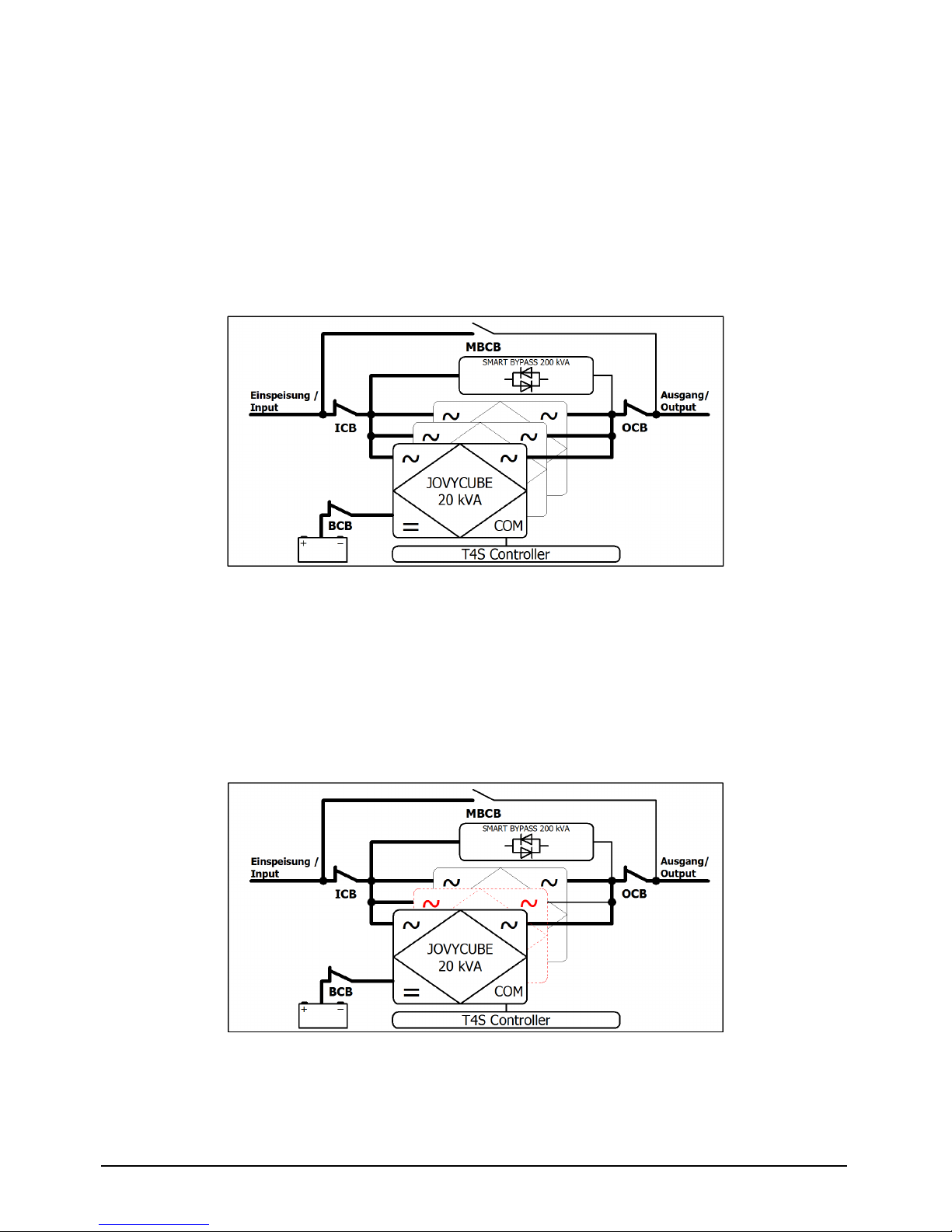
2.1 Functional description
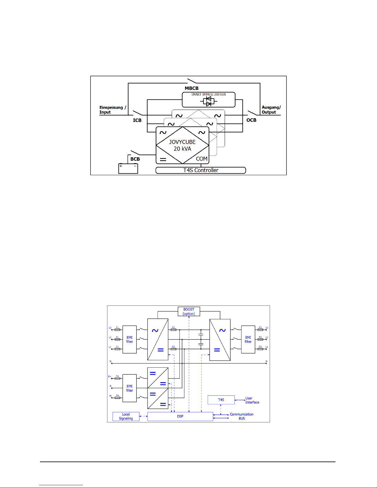
The block diagram shows the functional design of a JOVYCUBE UPS. It normally comprises several
parallel switched single modules. The "ICB", "MBCB", "BCB" and "OCB" switches are used to start and
shut down the UPS as well as to switch over to the bypass. Additionally, for maintenance purposes the
battery can be disconnected from the UPS. The drawing includes the optional static bypass (smart
bypass).
2
‑
1 Block diagram of a JOVYCUBE UPS
Key to the block diagram
Mains/bypass
→ UPS supply
ICB
→ Input Circuit Breaker
MBCB
→ Manual Bypass Circuit Breaker
BCB
→ Battery Circuit Breaker
OCB
→ Output Circuit Breaker
Output
→ Output for the connection of consumers
2.1.1 UPS module
One UPS module on its own in fact provides all the functionality of a conventional UPS system, including
a rectifier, inverter and battery charger.
The main benefit of these UPS modules lies in their hot-pluggable and hot-swap capability.
This means that in live operation you can plug additional modules into the UPS cabinet, provided there
are free slots available, and remove modules from it, provided the power supply of the remained
modules is sufficient.
2
‑
2 The block diagram gives an description of the topology and operation of a 20kVA module
WÄRTSILÄ JOVYCUBE 160 BAX 5157 - 9 -
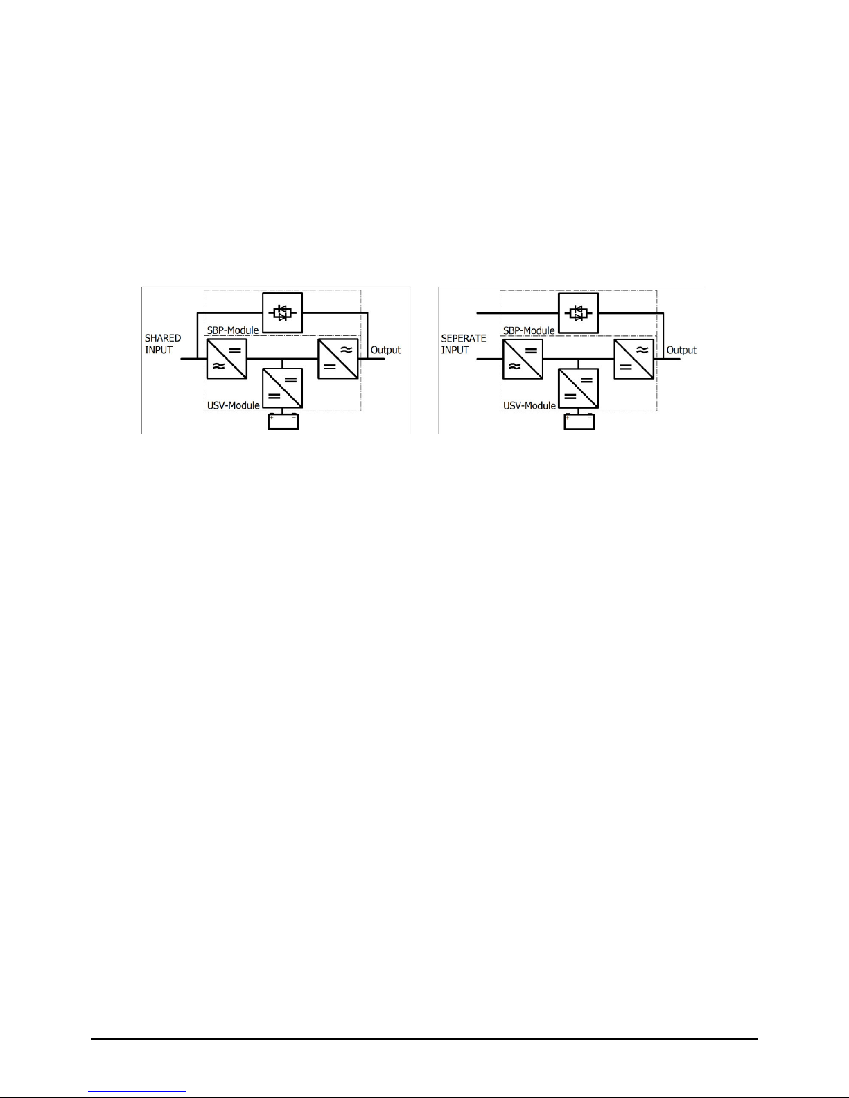
2.1.2 Static bypass module
Depending on the operating mode, the static bypass module (SBP module for short) improves the
consumers' supply reliability and/or saves energy. Thanks to the 200 kVA/kW output and a short-circuit
current of max. 2,900 A/20 ms per module and phase, fuse triggering due tom short circuits or load
surges presents no problem.
There are two operating modes available. These are set either using the switch on the module or in the
software.
In VFI mode (voltage and frequency independent), load is supplied through the UPS. The static switch
only becomes active in the event of a malfunction, of overload or if there is a short circuit. Load is applied
to the SBP module within 5 ms.
In ECO mode, load is supplied permanently via the SBP module. As mentioned above, this offers the
benefit of reduced energy consumption. In the event of failures and/or mains grid irregularities, battery
mode is engaged immediately, thus ensuring critical load.
2-1 Topology with shared input
2-2 Topology with separate input
As the diagrams show, the module is connected in parallel to the 20 kVA UPS modules.
The module's dimensions correspond to those of a UPS module. The SBP can therefore be retrofitted
into an existing system without difficulties provided there is sufficient space and shared input is ensured.
2.1.3 UPS system
A UPS system normally comprises several UPS modules interconnected inside a UPS cabinet by way
of a rail system which together supply the power needed by the connected consumers.
If you install an additional UPS module in such a UPS system you will be sure of maintaining the best
possible safe supply to connected consumers, as the redundant UPS module maintains the power
supply in the event of a technical fault in one of the primary modules.
In such a case you can easily and conveniently replace the faulty UPS module with a new one while the
other modules continue supplying the connected consumers.
2.1.4 Battery
The battery works in standby parallel operation, which means that the inverter, charger and battery are
permanently connected in parallel. To obtain the maximum lifetime of the battery it is protected by
floating operation according to DIN 41773.
2.1.5 Internal, manual bypass
Manual bypass is used to bypass parts of the UPS. In the event of maintenance or repair, the load is
supplied directly from the mains.
- 10 - BAX 5157 WÄRTSILÄ JOVYCUBE 160
2.2 Operating states
NOTE:
The block diagrams include the optional SBP static bypass. It is integrated into the system depending
on the UPS design.
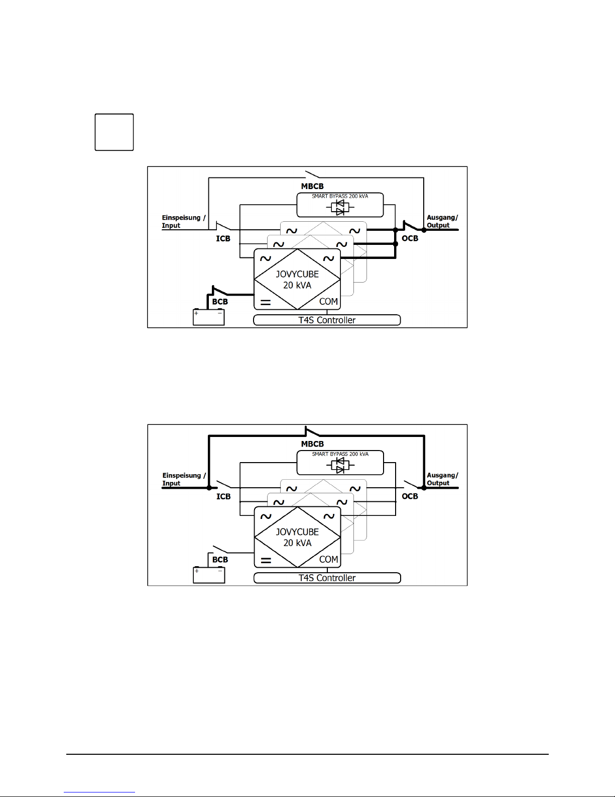
2.2.1 Normal operation
In normal operation, all the installed UPS modules supply the connected consumers, with the power
demand being spread equally across all the UPS modules.
Online operation
The mains feeds the rectifiers.
The rectifiers provide the DC voltage for the inverter and charge the battery.
The inverters supply the load at the output with the necessary energy.
2
‑
3 Online operation: load supplied via the inverter
2.2.2 Module error
The mains feeds the rectifiers.
The rectifiers provide the DC voltage for the inverter and charge the batteries.
In the event of a module error, the module concerned is shut down and the load is distributed
across the remaining modules, provided enough reserve is available. If not enough reserve was
available, the UPS would switch to overload mode and so supply to the consumers would no
longer be assured. For that reason, we recommend running a redundant 20kVA module in
parallel.
2
‑
4 Module error: Load supplied via the remaining UPS modules
WÄRTSILÄ JOVYCUBE 160 BAX 5157 - 11 -
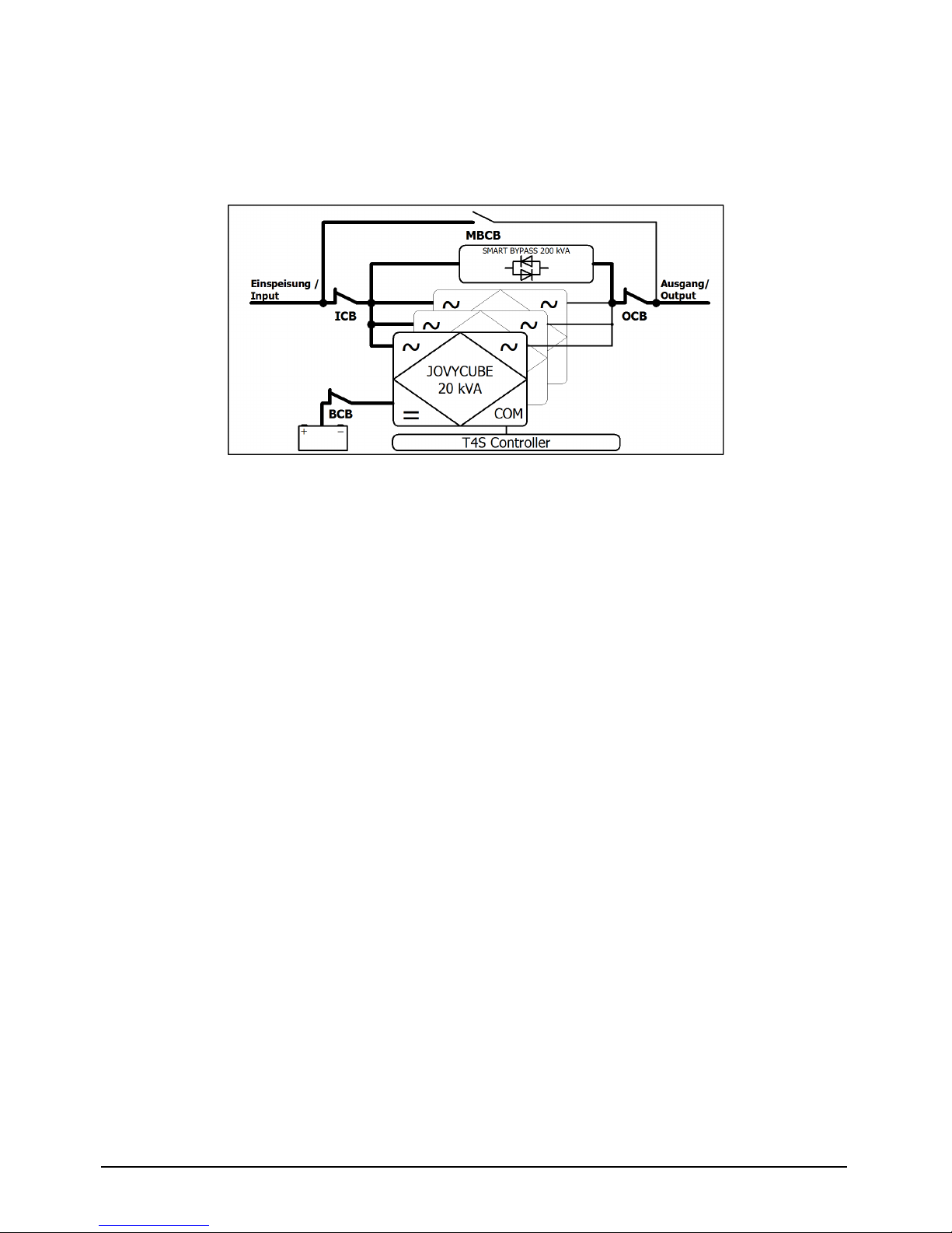
2.2.3 Mains failure
The battery provides the DC voltage for the inverters (for the duration of the stored energy time).
The inverter supplies the load at the output with the necessary energy.
If there is any threat of a deep battery discharge, the system automatically shuts down
completely and the load is no longer supplied with power.
Note:
In case of failure of one phase at the input, the load is proportionately supplied of the two
remaining phases and from the battery until it is discharged.
2
‑
5 Mains failure: load supplied via the inverter according to the stored energy time of the
batteries
2.2.4 Manual bypass
The load is supplied by the mains via the manual bypass.
Any necessary maintenance or repairs to the UPS can be carried out safely.
2
‑
6 Manual bypass Load supplied via the manual bypass
i
- 12 - BAX 5157 WÄRTSILÄ JOVYCUBE 160
2.2.5 Smart bypass
ECO mode:
The load at output is supplied by the mains via the static bypass.
The mains feeds the rectifiers.
The rectifiers supply the DC voltage and charge the batteries.
In the event of grid failure and/or irregularities in the supply, the UPS switches to battery mode
within 5 ms and supplies load via the UPS modules' inverters.
2-7 Bypass Mode: Load supplied via the smart bypass
Online mode (VFI):
The mains feeds the rectifiers.
The rectifiers provide the DC voltage for the inverter and charge the battery.
The inverters supply the load at the output with the necessary energy
(see Figure 2-3).
In the event of a fault, e.g. overload, short circuits or module malfunctions, the UPS switches to
bypass mode within 5 ms (see Figure 2-7) and supplies the load via the static bypass. Once the
faults have been rectified, online mode is immediately re-engaged.

WÄRTSILÄ JOVYCUBE 160 BAX 5157 - 13 -
3 Installation
Remove the packaging immediately after receiving the UPS and check the system for transport
damages. The transport company must be informed immediately after receipt of the UPS in the event
of any damage caused during transportation. If the UPS is not installed immediately it must be stored in
an upright position as indicated onthe packaging and kept in a dry, well ventilated room. If the UPS is
not stored in the original packaging, it must be protected from dust and moisture.
3.1 Installation
The UPS must be set up in a clean, dry, dust-free room. The operator must ensure that the room is
adequately ventilated, so that the system is sufficiently cooled and overheating is prevented. Please
observe the set-up diagram in the appendix. If the UPS is supplied with built-in batteries, the exchange
of air with the external environment must be in accordance with EN 62040, appendix N.
3.2 Electrical connections, cross sections, fuses
The electrical connection of the UPS unit is the task of the electrician providing the electrical installation
services. This task is not carried out by the UPS manufacturer. For this reason, the following
recommendations are only an indication, as the UPS manufacturer isnot responsible for the electrical
installation.
In all cases, we recommend installing and connecting the input and output in conformity with local
regulations and standards. In particular, take care to ensure a clockwise rotation phase sequence
during electrical installation. If no error message is generated, the Jovycube will also operate with an
anti-clockwise rotating field, and this may result in destruction of the UPS/modules if the manual bypass
is used. In the event that strong electromagnetic fields are emitted, we recommend the use of shielded
cables between the UPS and the load.
ATTENTION:
Even when the mains voltage is switched off there is a dangerously high battery voltage
inside the device. All installation and connection work may therefore only be carried out
by a qualified electrician. Before commencing work, electricians must read this manual
carefully to familiarize themselves with the special features of this UPS unit. The UPS
output still carries voltage even in the event of a mains failure. For this reason, the installer
must clearly label the outlets and sockets on the UPS unit in accordance with EN 62040!
ATTENTION:
The input line between the mains and the UPS unit must be protected against short
circuits!
The use of FI safety switches before the UPS unit is not recommended.

- 14 - BAX 5157 WÄRTSILÄ JOVYCUBE 160
3.2.1 Fuses and cross sections for cable connections to the UPS
The following table shows only dimensions (cable current carrying capacity in accordance with DIN VDE
0298-4) under defined, specified (operating) conditions. However, because the suitable cable crosssections have to be determined for each individual application with consideration for cable type, routing,
ambient temperature, cable bundling and cable lengths in accordance with VDE and local regulations,
these values are only applicable under these specific conditions.
The dimensions given below assume the following conditions:
H07V-K PVC-insulated single-core non-sheathed cable with a max. operating temperature of
70 °C
Cable routed through electric wiring conduit
Ambient temperature 30 °C
Cable bundling (group 2)
Max. 50 m cable length between load and UPS unit
Protective conductor dimensioning to VDE 0100 Part 540
400V alternating voltage
160 kVA
WÄRTSILÄ
JOVYCUBE
Cross section [mm²]
(phases + N / PE)
Recommended
fusing [A]
Rectifier input
4 x 95 / 1 x 50 3 x 250
UPS output
4 x 95 / 1 x 50 -
Battery B+, B
-
, N
2 x 3 x 95 / 1 x 95 3 x 500
3.2.2 Connections to the UPS
The UPS should be connected up as shown in the technical drawings in the appendix at the end of
this operating manual.
Attention:
The max. Voltage and current of the potential free message contacts is
30VDC/2A.
Notice:
In normal mode, the feed's neutral line is required under all circumstances. If
this cannot be ensured, a transformer forming a neutral point needs to be
connected upstream.
3.2.3 Mounting and connecting the battery
Please refer to the technical drawings in the appendix of this operating manual for information on
mounting and connecting the battery to the UPS.
Attention:
Unless otherwise noted, the battery cables of the battery cabinets or strings must
be connected directly to the UPS.
The reason is the reduced cross section of the cable.
Note:
Observe DIN EN 50272 when setting up the battery.
WÄRTSILÄ JOVYCUBE 160 BAX 5157 - 15 -
4 Operation
The operation is exclusively over the modules (ON/OFF-Switch).
The information gathering such as voltages, currents, power etc is done via the control unit (T4S*) or
the optional 7 inch touchscreen. In both versions, a connection can be established via IP, from the
display or the RJ-45 port in the connector panel, to a PC. For this purpose, only a web browser such as
Mozilla Firefox and a patch cord (not supplied) is required.
The IP address is set in the factory to 192.168.0.2 and can be changed in its sole discretion.
The password for the basic access is set from the factory to pass123 and can be changed at your
discretion. The expert mode is reserved exclusively for the company WÄRTSILÄ JOVYATLAS.
4.1 Software overview
The software embedded in T4S and the Display allows complete system supervision through
“touchscreen display” or via web browser, and provides functionalities such as:
System setting and configuration (password protected)
System status and information display
System alarms and events log file.
System-self-maintenance (battery test, battery boost charge, ...)
- 16 - BAX 5157 WÄRTSILÄ JOVYCUBE 160
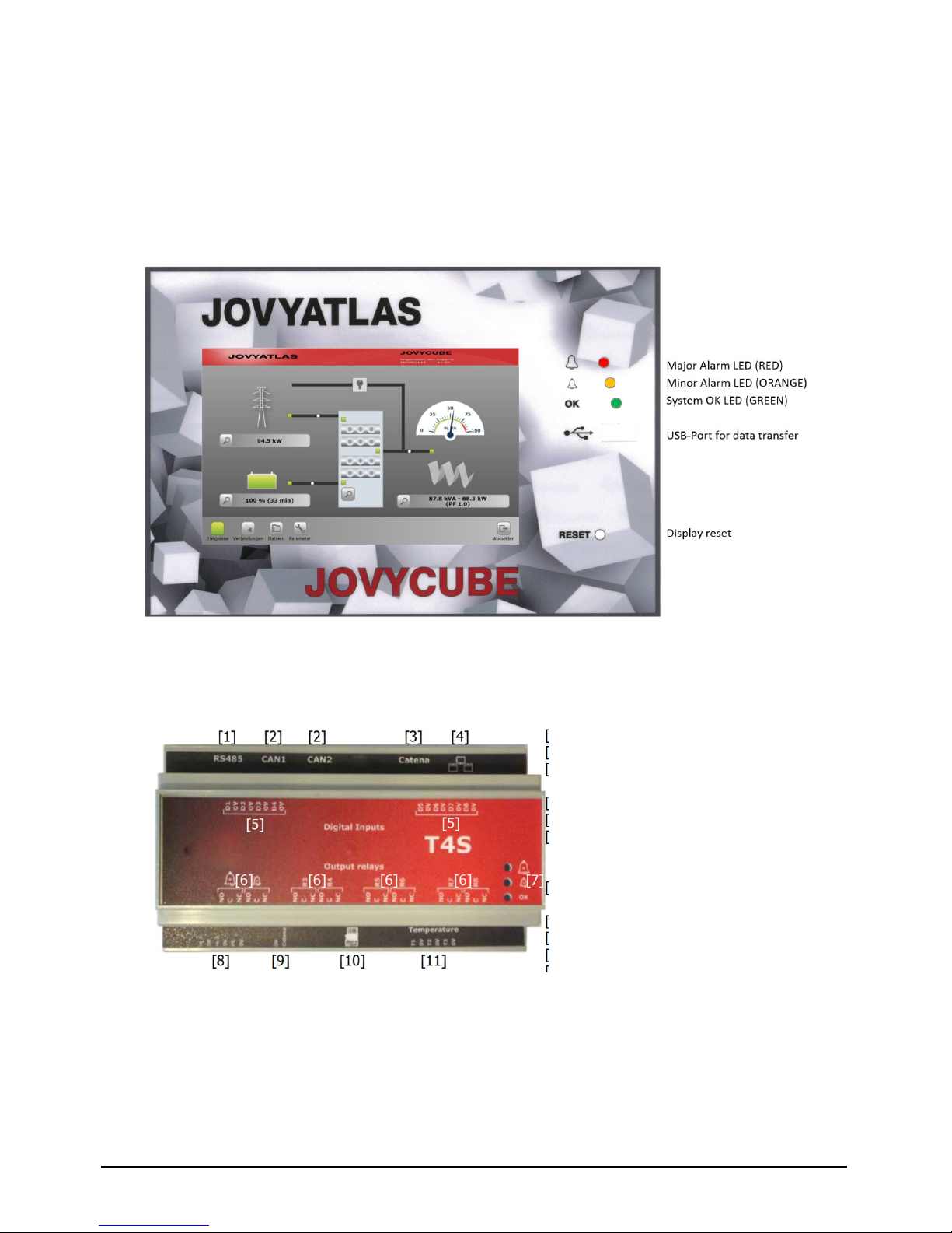
4.2 Touchscreen Display
The 7" touchscreen display provides easy access to system monitoring via a powerful web-based
graphic display. Along with the display there is also PC-based access to the same GUI via the
Ethernet port provided as standard on the front panel.
There are two versions of the display:
Rack installation:
The display is flush-mounted in the cabinet instead of a 20 kVA module.
Door installation:
The display is installed in the door. Note that in this case the
protection class is lower – IP20.
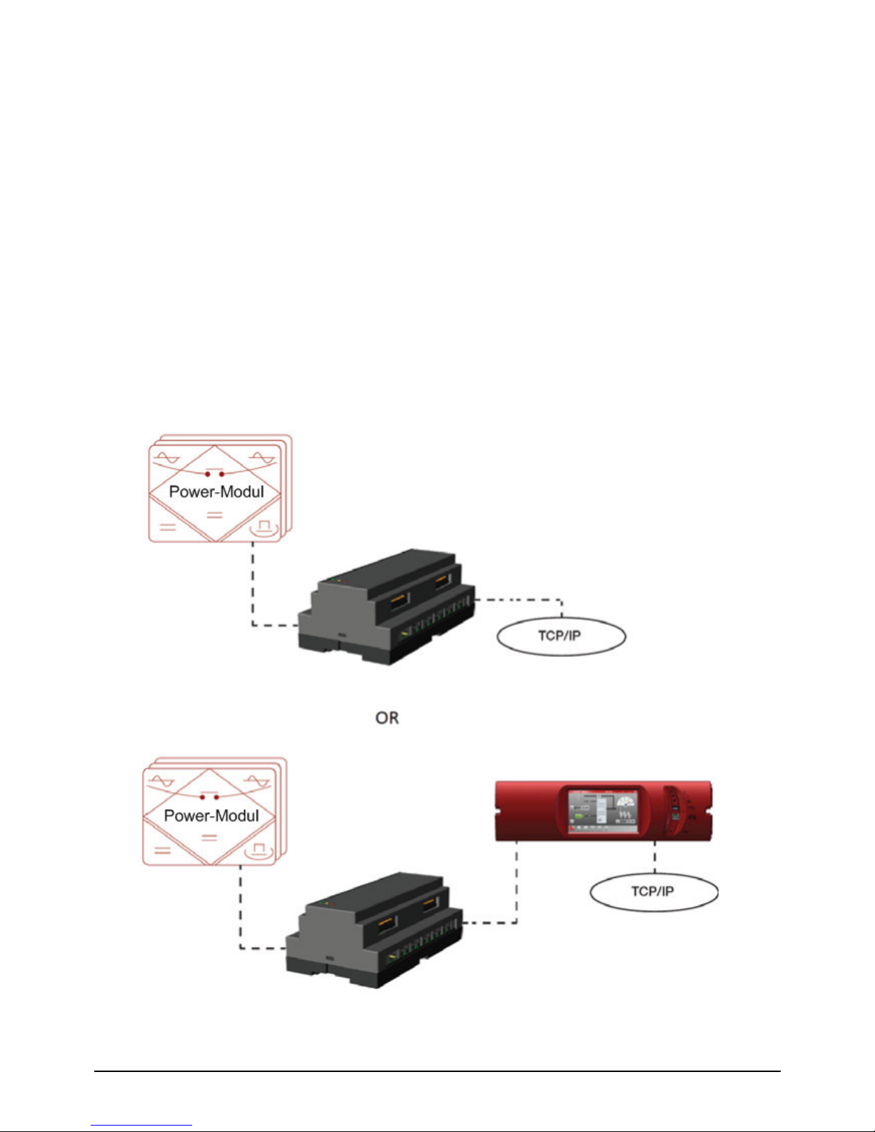
4.3 Controller T4S
The T4S is the central control unit which stored all parameters, controlled the modules and sent
information’s via SNMP or RJ45 interface.
[1]
1 x RS485
[2]
2 x CAN-BUS
[3]
Communication bus to the
display
[4]
Ethernet-Port
[5]
Digital inputs
[6]
Potential free message
contacts
(Max 30V/2A)
[7]
3 x Status-LEDs
(Major/Minor/OK)
[8]
Power supply (2x 12VDC)
[9]
Power supply Display
[10]
Memory card(Micro-SD)
[11]
Inputs 3x temperature sensors
WÄRTSILÄ JOVYCUBE 160 BAX 5157 - 17 -
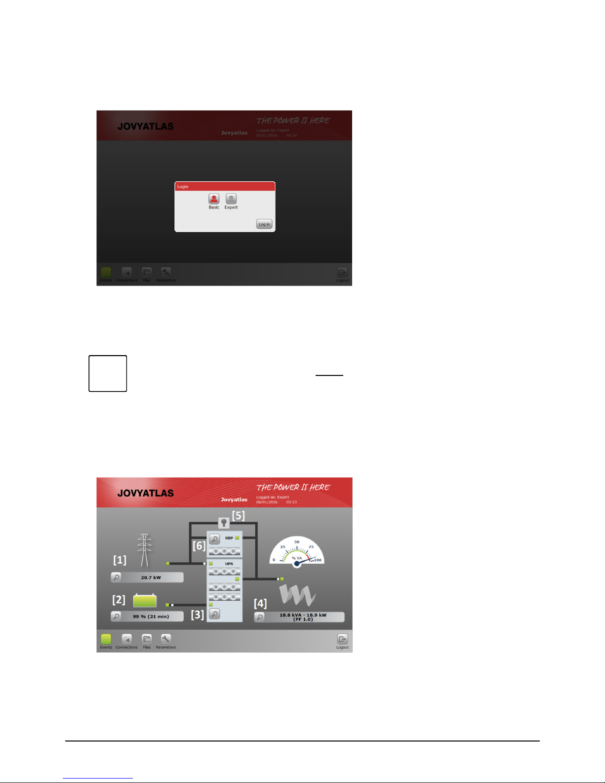
4.4 Startup/Login
As described in section 5, the system can be accessed via either the display or via web browser. To
access the system via web browser, enter IP address 192.168.0.2 in the browser address bar and
confirm.
Both versions have the same interface structure:
The login screen gives you two
access options:
BASIC:
This is only for the purpose
of obtaining information.
Changes are not allowed.
EXPERT:
Allows system parameters
to be modified and
changed.
The default factory-set password for basic access is pass123 and can be changed at your own
discretion (If you lose the password, a change is no longer possible. This has the consequence that a
service technician from WÄRTSILÄ JOVYATLAS needs to update the software). Expert mode is
reserved exclusively for WÄRTSILÄ JOVYATLAS.
NOTE:
The values explained in the sections below cannot be changed in BASIC access mode.
Changes can only be made by trained personnel in EXPERT access mode.
4.5 Standard functions
The main screen displays the status and current measured values of the system components.
For details, simply click on the relevant magnifier icon:
[1] AC input
Green: OK
Red: Mains fault
[2] Battery
Green: OK/charge
Amber: OK/discharge
Red: Battery fault
[3] UPS module
3-status LEDs:
AC-IN
AC-OUT
BATTERY
[4] AC output
Green: Inverter feeding load
Amber: Load >75%
Red: Inverter not feeding load
[5] Manual bypass
[6] Static bypass
The symbol is only visible when
using an SBP module.
i
 Loading...