

Page 1
Operating Instructions
EN
Navigation Echo Sounder
Wärtsilä ELAC LAZ 5200
Wärtsilä ELAC Nautik GmbH
TH 526148001 EN
Rev. A
09/2018
IMPORTANT
READ CAREFULLY BEFORE USE
KEEP IN A SAFE PLACE FOR FUTURE REFERENCE
Page 2

Page 3
ELAC LAZ5200 – Operating Instructions
Foreword
Wärtsilä ELAC Nautik GmbH manufactures state-of-the-art quality products.
The present document provides important information and knowledge for the safe, proper
and efficient use of your product from Wärtsilä ELAC Nautik GmbH.
Ensure that you are using the correct and latest document on your acquired product.
Contact the manufacturer for the appropriate revision and issue of the document corresponding to the release status of the product.
This document forms an integral part of the product. Keep it in a safe place where it is
readily accessible during the whole service life of the product and ensure that it is made
available to the new owner if the product is sold or passed on.
For further questions relating to the product or to this document, please contact:
Wärtsilä ELAC Nautik GmbH
Neufeldtstrasse 10
24118 Kiel
Germany
: +49 431 883-0
: +49 431 883-496
@: marketing@elac-wartsila.de
If you have any technical questions relating to the product or to the handling of the product, please contact:
Service Wärtsilä ELAC Nautik GmbH
: +49 431 883-388
: +49 431 883-366
@: support@elac-wartsila.de
Protection notice to ISO 16016
The reproduction, distribution and utilisation of this document as well as the communication of its contents to others without explicit authorisation is prohibited. Offenders will be
held liable for the payment of damages. All rights reserved in the event of a patent, utility
model or design registration.
© 2018 Wärtsilä ELAC Nautik GmbH, Neufeldtstrasse 10, D-24118 Kiel.
Software-Licence Agreement
Should this manual be delivered together with software, whether embedded or separate,
then manual and software are subject to a licence agreement between you and Wärtsilä
Refer to protection notice ISO 16016
ELAC Nautik GmbH.
All rights and obligations deriving therefrom and arising in connection therewith can be
retrieved from the licence texts also provided.
TH 526148001 EN Rev. A 09/2018 Wärtsilä ELAC Nautik GmbH 1 / 134
Page 4

ELAC LAZ5200 – Operating Instructions
Open source software license notice
To the extent the license terms applicable to open source software components included
in our product require Wärtsilä ELAC Nautik GmbH to make an offer to provide the source
code of the open source licensed software or otherwise entitle the customer to receive a
copy of the source code of the open source licensed software, such offer is hereby made.
In case you wish to receive a copy of the source code of such open source software you
are entitled to under the applicable open source software license terms, please contact
Wärtsilä ELAC Nautik GmbH.
Intellectual property rights
The mark ELAC is a Community Trade and Word Mark registered with the Office for Harmonization in the Internal Market under registration no. 009254186 as well as a Figurative Mark registered with the same office under registration no. 009254384.
Revision index
The following revision index summarises the changes compared with the last issue (revision) of the document.
Type of revision
Page(s) Section
new revised
32 3.4 X
Comment Author
Technical data
modified
LZ/FA
2 / 134 Wärtsilä ELAC Nautik GmbH TH 526148001 EN Rev. A 09/2018
Refer to protection notice ISO 16016
Page 5

ELAC LAZ5200 – Operating Instructions
Table of Contents
Page
1 About this Document . . . . . . . . . . . . . . . . . . . . . . . . . . . . . . . . . . . . . . . . . . 15
1.1 Purpose of this Document . . . . . . . . . . . . . . . . . . . . . . . . . . . . . . . . . . . . . . . . . . . 15
1.2 Target Groups . . . . . . . . . . . . . . . . . . . . . . . . . . . . . . . . . . . . . . . . . . . . . . . . . . . . . 15
1.3 Obligation to Read this Document. . . . . . . . . . . . . . . . . . . . . . . . . . . . . . . . . . . . . 15
1.4 Obligation to Store and Pass On this Document . . . . . . . . . . . . . . . . . . . . . . . . . 15
1.5 Note on Completeness of Cited Laws and Standards . . . . . . . . . . . . . . . . . . . . . 15
1.6 Representation Conventions . . . . . . . . . . . . . . . . . . . . . . . . . . . . . . . . . . . . . . . . . 16
1.6.1 Presentation of Warnings. . . . . . . . . . . . . . . . . . . . . . . . . . . . . . . . . . . . . . . . . . . . . . 16
1.6.2 Presentation of Warnings of Potential Damage. . . . . . . . . . . . . . . . . . . . . . . . . . . . . 17
1.6.3 Presentation of Other Warnings. . . . . . . . . . . . . . . . . . . . . . . . . . . . . . . . . . . . . . . . . 18
1.6.4 Other Symbols and Markings . . . . . . . . . . . . . . . . . . . . . . . . . . . . . . . . . . . . . . . . . . 18
1.6.5 Text Markups . . . . . . . . . . . . . . . . . . . . . . . . . . . . . . . . . . . . . . . . . . . . . . . . . . . . . . . 19
2 Safety . . . . . . . . . . . . . . . . . . . . . . . . . . . . . . . . . . . . . . . . . . . . . . . . . . . . . . . 21
2.1 Preliminary Remark on Chapter "Safety" . . . . . . . . . . . . . . . . . . . . . . . . . . . . . . . 21
2.2 Intended Use . . . . . . . . . . . . . . . . . . . . . . . . . . . . . . . . . . . . . . . . . . . . . . . . . . . . . . 21
2.3 Foreseeable Misuse. . . . . . . . . . . . . . . . . . . . . . . . . . . . . . . . . . . . . . . . . . . . . . . . . 21
2.4 Personal Protective Equipment . . . . . . . . . . . . . . . . . . . . . . . . . . . . . . . . . . . . . . . 22
2.5 System Damage due to Unauthorised Modification. . . . . . . . . . . . . . . . . . . . . . . 22
2.6 Fundamental Safety Precautions. . . . . . . . . . . . . . . . . . . . . . . . . . . . . . . . . . . . . . 23
2.7 Specific Safety Precautions . . . . . . . . . . . . . . . . . . . . . . . . . . . . . . . . . . . . . . . . . . 24
2.8 Personnel Qualifications. . . . . . . . . . . . . . . . . . . . . . . . . . . . . . . . . . . . . . . . . . . . . 24
2.9 Obligations of the Owner . . . . . . . . . . . . . . . . . . . . . . . . . . . . . . . . . . . . . . . . . . . . 25
2.10 Requirements for the Workplace . . . . . . . . . . . . . . . . . . . . . . . . . . . . . . . . . . . . . . 25
2.11 Further Regulations to be Observed . . . . . . . . . . . . . . . . . . . . . . . . . . . . . . . . . . . 26
2.12 Disposal and Recycling . . . . . . . . . . . . . . . . . . . . . . . . . . . . . . . . . . . . . . . . . . . . . 26
2.12.1 Disposal and Recycling . . . . . . . . . . . . . . . . . . . . . . . . . . . . . . . . . . . . . . . . . . . . . . . 26
2.12.2 Batteries. . . . . . . . . . . . . . . . . . . . . . . . . . . . . . . . . . . . . . . . . . . . . . . . . . . . . . . . . . . 26
2.12.3 Electrical and Electronic Scrap . . . . . . . . . . . . . . . . . . . . . . . . . . . . . . . . . . . . . . . . . 26
2.12.4 Auxiliary, Process and Cleaning Media . . . . . . . . . . . . . . . . . . . . . . . . . . . . . . . . . . . 26
3 Technical Description. . . . . . . . . . . . . . . . . . . . . . . . . . . . . . . . . . . . . . . . . . 27
3.1 Functional Description . . . . . . . . . . . . . . . . . . . . . . . . . . . . . . . . . . . . . . . . . . . . . . 27
3.2 Component Overview . . . . . . . . . . . . . . . . . . . . . . . . . . . . . . . . . . . . . . . . . . . . . . . 27
3.3 Description of the Components . . . . . . . . . . . . . . . . . . . . . . . . . . . . . . . . . . . . . . . 28
3.3.1 Navigation Echo Sounder ELAC LAZ 5200. . . . . . . . . . . . . . . . . . . . . . . . . . . . . . . . 28
3.3.2 Distribution Box VK 10. . . . . . . . . . . . . . . . . . . . . . . . . . . . . . . . . . . . . . . . . . . . . . . . 29
3.3.3 Ultrasonic Transducer . . . . . . . . . . . . . . . . . . . . . . . . . . . . . . . . . . . . . . . . . . . . . . . . 30
3.3.4 Digital Slave Display (Option) . . . . . . . . . . . . . . . . . . . . . . . . . . . . . . . . . . . . . . . . . . 31
3.3.5 Printer (Option) . . . . . . . . . . . . . . . . . . . . . . . . . . . . . . . . . . . . . . . . . . . . . . . . . . . . . 31
3.3.6 Unlocking Tool . . . . . . . . . . . . . . . . . . . . . . . . . . . . . . . . . . . . . . . . . . . . . . . . . . . . . . 31
Refer to protection notice ISO 16016
3.4 Technical Data – Navigation Echo Sounder ELAC LAZ 5200 . . . . . . . . . . . . . . . 32
4 Installation . . . . . . . . . . . . . . . . . . . . . . . . . . . . . . . . . . . . . . . . . . . . . . . . . . . 35
TH 526148001 EN Rev. A 09/2018 Wärtsilä ELAC Nautik GmbH 3 / 134
Page 6

ELAC LAZ5200 – Operating Instructions
Page
4.1 Section Safety Messages . . . . . . . . . . . . . . . . . . . . . . . . . . . . . . . . . . . . . . . . . . . . 35
4.2 Preparation for Installation . . . . . . . . . . . . . . . . . . . . . . . . . . . . . . . . . . . . . . . . . . . 37
4.2.1 General Information on Cable Laying . . . . . . . . . . . . . . . . . . . . . . . . . . . . . . . . . . . . 37
4.2.2 General Information on Transducer Installation. . . . . . . . . . . . . . . . . . . . . . . . . . . . . 38
4.2.3 Earthing . . . . . . . . . . . . . . . . . . . . . . . . . . . . . . . . . . . . . . . . . . . . . . . . . . . . . . . . . . . 38
4.3 Description of the Installation Work . . . . . . . . . . . . . . . . . . . . . . . . . . . . . . . . . . . 40
4.3.1 Installation of Navigation Echo Sounder ELAC LAZ 5200. . . . . . . . . . . . . . . . . . . . . 40
4.3.2 Installation of Transducer. . . . . . . . . . . . . . . . . . . . . . . . . . . . . . . . . . . . . . . . . . . . . . 40
4.3.3 Installation of Navigation Echo Sounder ELAC LAZ 5200 Connection Cable . . . . . . 41
4.3.3.1 Overview Pin Assignment Navigation Echo Sounder ELAC LAZ 5200 . . . . . . . . . . . . . . . . . . 41
4.3.3.2 Installation of Navigation Echo Sounder ELAC LAZ 5200 Connection Cable . . . . . . . . . . . . . 41
5 Commissioning (Configuration) . . . . . . . . . . . . . . . . . . . . . . . . . . . . . . . . . 45
6 Operation. . . . . . . . . . . . . . . . . . . . . . . . . . . . . . . . . . . . . . . . . . . . . . . . . . . . 47
6.1 Section Safety Messages . . . . . . . . . . . . . . . . . . . . . . . . . . . . . . . . . . . . . . . . . . . . 47
6.2 Operating and Display Elements . . . . . . . . . . . . . . . . . . . . . . . . . . . . . . . . . . . . . . 48
6.2.1 Overview – Operating and Display Elements of Navigation Echo Sounder
ELAC LAZ 5200. . . . . . . . . . . . . . . . . . . . . . . . . . . . . . . . . . . . . . . . . . . . . . . . . . . . . 48
6.2.2 Keyboard . . . . . . . . . . . . . . . . . . . . . . . . . . . . . . . . . . . . . . . . . . . . . . . . . . . . . . . . . . 49
6.2.3 Description of the Operating and Display Elements . . . . . . . . . . . . . . . . . . . . . . . . . 50
6.2.3.1 [CURSOR] Keys . . . . . . . . . . . . . . . . . . . . . . . . . . . . . . . . . . . . . . . . . . . . . . . . . . . . . . . . . . . 50
6.2.3.2 [ESCAPE] Key and [ENTER] Key . . . . . . . . . . . . . . . . . . . . . . . . . . . . . . . . . . . . . . . . . . . . . . 50
6.2.3.3 [PRINT] Key. . . . . . . . . . . . . . . . . . . . . . . . . . . . . . . . . . . . . . . . . . . . . . . . . . . . . . . . . . . . . . . 50
6.2.3.4 [MARKER] Key . . . . . . . . . . . . . . . . . . . . . . . . . . . . . . . . . . . . . . . . . . . . . . . . . . . . . . . . . . . . 50
6.2.3.5 Confirmation Key . . . . . . . . . . . . . . . . . . . . . . . . . . . . . . . . . . . . . . . . . . . . . . . . . . . . . . . . . . . 51
6.2.3.6 [GAIN] Keys. . . . . . . . . . . . . . . . . . . . . . . . . . . . . . . . . . . . . . . . . . . . . . . . . . . . . . . . . . . . . . . 51
6.2.3.7 [RANGE] Keys. . . . . . . . . . . . . . . . . . . . . . . . . . . . . . . . . . . . . . . . . . . . . . . . . . . . . . . . . . . . . 51
6.2.3.8 [DIM] Keys . . . . . . . . . . . . . . . . . . . . . . . . . . . . . . . . . . . . . . . . . . . . . . . . . . . . . . . . . . . . . . . . 51
6.2.3.9 [ON] Key and [OFF] Key . . . . . . . . . . . . . . . . . . . . . . . . . . . . . . . . . . . . . . . . . . . . . . . . . . . . . 51
6.3 Graphical User Interface . . . . . . . . . . . . . . . . . . . . . . . . . . . . . . . . . . . . . . . . . . . . . 52
6.3.1 Graphical User Interface – Overview. . . . . . . . . . . . . . . . . . . . . . . . . . . . . . . . . . . . . 52
6.3.2 Elements of the User Interface . . . . . . . . . . . . . . . . . . . . . . . . . . . . . . . . . . . . . . . . . 53
6.3.2.1 Information Field . . . . . . . . . . . . . . . . . . . . . . . . . . . . . . . . . . . . . . . . . . . . . . . . . . . . . . . . . . . 53
6.3.2.2 Display Area. . . . . . . . . . . . . . . . . . . . . . . . . . . . . . . . . . . . . . . . . . . . . . . . . . . . . . . . . . . . . . . 55
6.3.2.3 Status Bar . . . . . . . . . . . . . . . . . . . . . . . . . . . . . . . . . . . . . . . . . . . . . . . . . . . . . . . . . . . . . . . . 58
6.3.2.4 Description of NON-IMO Mode . . . . . . . . . . . . . . . . . . . . . . . . . . . . . . . . . . . . . . . . . . . . . . . . 59
6.3.2.5 Description of the Depth Alarm . . . . . . . . . . . . . . . . . . . . . . . . . . . . . . . . . . . . . . . . . . . . . . . . 59
6.4 Description of the Menus . . . . . . . . . . . . . . . . . . . . . . . . . . . . . . . . . . . . . . . . . . . . 61
6.4.1 “MAIN MENU” . . . . . . . . . . . . . . . . . . . . . . . . . . . . . . . . . . . . . . . . . . . . . . . . . . . . . . 61
6.4.2 “SETTINGS” Menu . . . . . . . . . . . . . . . . . . . . . . . . . . . . . . . . . . . . . . . . . . . . . . . . . . 62
6.4.3 “ALARM SETUP” Menu . . . . . . . . . . . . . . . . . . . . . . . . . . . . . . . . . . . . . . . . . . . . . . . 63
6.4.4 “NETWORK” Menu . . . . . . . . . . . . . . . . . . . . . . . . . . . . . . . . . . . . . . . . . . . . . . . . . . 64
6.4.5 “SERIAL INTERFACES” Menu . . . . . . . . . . . . . . . . . . . . . . . . . . . . . . . . . . . . . . . . . 65
6.4.6 Interface Configuration . . . . . . . . . . . . . . . . . . . . . . . . . . . . . . . . . . . . . . . . . . . . . . . 66
6.4.7 “SYSTEM SETUP” Menu. . . . . . . . . . . . . . . . . . . . . . . . . . . . . . . . . . . . . . . . . . . . . . 67
6.4.8 “Replay” Function . . . . . . . . . . . . . . . . . . . . . . . . . . . . . . . . . . . . . . . . . . . . . . . . . . . 68
Refer to protection notice ISO 16016
4 / 134 Wärtsilä ELAC Nautik GmbH TH 526148001 EN Rev. A 09/2018
Page 7

ELAC LAZ5200 – Operating Instructions
Page
6.4.9 “Auto Mode” Function . . . . . . . . . . . . . . . . . . . . . . . . . . . . . . . . . . . . . . . . . . . . . . . . 68
6.5 Operation of the System . . . . . . . . . . . . . . . . . . . . . . . . . . . . . . . . . . . . . . . . . . . . . 69
6.5.1 General . . . . . . . . . . . . . . . . . . . . . . . . . . . . . . . . . . . . . . . . . . . . . . . . . . . . . . . . . . . 69
6.5.2 Switching ON the Navigation Echo Sounder ELAC LAZ 5200 . . . . . . . . . . . . . . . . . 69
6.5.3 Switching OFF the Navigation Echo Sounder ELAC LAZ 5200 . . . . . . . . . . . . . . . . 70
6.5.4 Operation of the Menu. . . . . . . . . . . . . . . . . . . . . . . . . . . . . . . . . . . . . . . . . . . . . . . . 70
6.5.4.1 Opening the Menu . . . . . . . . . . . . . . . . . . . . . . . . . . . . . . . . . . . . . . . . . . . . . . . . . . . . . . . . . . 70
6.5.4.2 Navigate in Menu . . . . . . . . . . . . . . . . . . . . . . . . . . . . . . . . . . . . . . . . . . . . . . . . . . . . . . . . . . . 71
6.5.4.3 Changing a Parameter Value. . . . . . . . . . . . . . . . . . . . . . . . . . . . . . . . . . . . . . . . . . . . . . . . . . 72
6.5.4.4 Unlocking a Sub-menu. . . . . . . . . . . . . . . . . . . . . . . . . . . . . . . . . . . . . . . . . . . . . . . . . . . . . . . 72
6.5.4.5 Closing the Menu . . . . . . . . . . . . . . . . . . . . . . . . . . . . . . . . . . . . . . . . . . . . . . . . . . . . . . . . . . . 73
6.5.5 Settings for the Depth Measurement. . . . . . . . . . . . . . . . . . . . . . . . . . . . . . . . . . . . . 74
6.5.5.1 Setting the Depth Measuring Range . . . . . . . . . . . . . . . . . . . . . . . . . . . . . . . . . . . . . . . . . . . . 74
6.5.5.2 Activating and Deactivating the "Auto Gain" Function . . . . . . . . . . . . . . . . . . . . . . . . . . . . . . . 75
6.5.5.3 Manual Setting of the Reception Gain ("GAIN") . . . . . . . . . . . . . . . . . . . . . . . . . . . . . . . . . . . 76
6.5.5.4 Activation of the "Auto Mode" Function . . . . . . . . . . . . . . . . . . . . . . . . . . . . . . . . . . . . . . . . . . 77
6.5.5.5 Selecting the Active Channels . . . . . . . . . . . . . . . . . . . . . . . . . . . . . . . . . . . . . . . . . . . . . . . . . 78
6.5.6 Settings for the Depth Alarm . . . . . . . . . . . . . . . . . . . . . . . . . . . . . . . . . . . . . . . . . . . 79
6.5.6.1 Activating and Deactivating the Depth Alarm. . . . . . . . . . . . . . . . . . . . . . . . . . . . . . . . . . . . . . 79
6.5.6.2 Setting the Alarm Limits . . . . . . . . . . . . . . . . . . . . . . . . . . . . . . . . . . . . . . . . . . . . . . . . . . . . . . 80
6.5.6.3 Activation of the Test Alarm . . . . . . . . . . . . . . . . . . . . . . . . . . . . . . . . . . . . . . . . . . . . . . . . . . . 81
6.5.7 Settings for the Display . . . . . . . . . . . . . . . . . . . . . . . . . . . . . . . . . . . . . . . . . . . . . . . 82
6.5.7.1 Selection of the Reference Point . . . . . . . . . . . . . . . . . . . . . . . . . . . . . . . . . . . . . . . . . . . . . . . 82
6.5.7.2 Selection of the Unit for the Depth Display . . . . . . . . . . . . . . . . . . . . . . . . . . . . . . . . . . . . . . . 83
6.5.7.3 Selection of the Display Colour . . . . . . . . . . . . . . . . . . . . . . . . . . . . . . . . . . . . . . . . . . . . . . . . 84
6.5.7.4 Setting of the Background Lighting . . . . . . . . . . . . . . . . . . . . . . . . . . . . . . . . . . . . . . . . . . . . . 85
6.5.8 “History” View . . . . . . . . . . . . . . . . . . . . . . . . . . . . . . . . . . . . . . . . . . . . . . . . . . . . . . 86
6.5.8.1 Opening the History . . . . . . . . . . . . . . . . . . . . . . . . . . . . . . . . . . . . . . . . . . . . . . . . . . . . . . . . . 87
6.5.8.2 Scrolling in the History . . . . . . . . . . . . . . . . . . . . . . . . . . . . . . . . . . . . . . . . . . . . . . . . . . . . . . . 87
6.5.8.3 Controlling the Cursor in the History . . . . . . . . . . . . . . . . . . . . . . . . . . . . . . . . . . . . . . . . . . . . 88
6.5.8.4 Closing the History . . . . . . . . . . . . . . . . . . . . . . . . . . . . . . . . . . . . . . . . . . . . . . . . . . . . . . . . . . 88
6.5.9 Print ("PRINT"). . . . . . . . . . . . . . . . . . . . . . . . . . . . . . . . . . . . . . . . . . . . . . . . . . . . . . 88
6.5.10 Exporting of Recorded Data . . . . . . . . . . . . . . . . . . . . . . . . . . . . . . . . . . . . . . . . . . . 89
6.5.11 Configuration . . . . . . . . . . . . . . . . . . . . . . . . . . . . . . . . . . . . . . . . . . . . . . . . . . . . . . . 90
6.5.11.1 Configuration of a Channel . . . . . . . . . . . . . . . . . . . . . . . . . . . . . . . . . . . . . . . . . . . . . . . . . . . 90
6.5.11.2 Configuring the Network Settings for the Navigation Echo Sounder ELAC LAZ 5200 . . . . . . 92
6.5.11.3 Configuring the Network Settings of the Printer. . . . . . . . . . . . . . . . . . . . . . . . . . . . . . . . . . . .93
6.5.11.4 Configuring the Ethernet Interface . . . . . . . . . . . . . . . . . . . . . . . . . . . . . . . . . . . . . . . . . . . . . . 94
6.5.11.5 Configuration of the Serial Interfaces. . . . . . . . . . . . . . . . . . . . . . . . . . . . . . . . . . . . . . . . . . . . 97
6.5.11.6 Setting the Draft . . . . . . . . . . . . . . . . . . . . . . . . . . . . . . . . . . . . . . . . . . . . . . . . . . . . . . . . . . . . 99
6.5.11.7 Setting of the Date and Time . . . . . . . . . . . . . . . . . . . . . . . . . . . . . . . . . . . . . . . . . . . . . . . . . . 99
6.5.11.8 Setting the Alarm ID. . . . . . . . . . . . . . . . . . . . . . . . . . . . . . . . . . . . . . . . . . . . . . . . . . . . . . . . 102
6.5.11.9 Restoring the Factory Settings. . . . . . . . . . . . . . . . . . . . . . . . . . . . . . . . . . . . . . . . . . . . . . . . 103
Refer to protection notice ISO 16016
7 Troubleshooting and Remedy . . . . . . . . . . . . . . . . . . . . . . . . . . . . . . . . . . 105
8 Preventive Maintenance . . . . . . . . . . . . . . . . . . . . . . . . . . . . . . . . . . . . . . . 107
8.1 Section Safety Messages . . . . . . . . . . . . . . . . . . . . . . . . . . . . . . . . . . . . . . . . . . . 107
TH 526148001 EN Rev. A 09/2018 Wärtsilä ELAC Nautik GmbH 5 / 134
Page 8

ELAC LAZ5200 – Operating Instructions
Page
8.2 Tools, Measuring Devices and Equipment . . . . . . . . . . . . . . . . . . . . . . . . . . . . . 107
8.2.1 Tools . . . . . . . . . . . . . . . . . . . . . . . . . . . . . . . . . . . . . . . . . . . . . . . . . . . . . . . . . . . . 107
8.2.2 Measuring and Test Devices . . . . . . . . . . . . . . . . . . . . . . . . . . . . . . . . . . . . . . . . . . 107
8.2.3 Process Media and Materials . . . . . . . . . . . . . . . . . . . . . . . . . . . . . . . . . . . . . . . . . 107
8.2.4 Cleaning Equipment and Cleaning Agents . . . . . . . . . . . . . . . . . . . . . . . . . . . . . . . 108
8.3 Maintenance intervals / maintenance plan . . . . . . . . . . . . . . . . . . . . . . . . . . . . . 108
8.4 Description of the Maintenance Tasks . . . . . . . . . . . . . . . . . . . . . . . . . . . . . . . . 109
8.4.1 Cleaning of the Navigation Echo Sounder ELAC LAZ 5200 . . . . . . . . . . . . . . . . . . 109
8.4.2 Cleaning the Transducer . . . . . . . . . . . . . . . . . . . . . . . . . . . . . . . . . . . . . . . . . . . . . 110
9 Appendix . . . . . . . . . . . . . . . . . . . . . . . . . . . . . . . . . . . . . . . . . . . . . . . . . . . 111
9.1 Applicable Documents . . . . . . . . . . . . . . . . . . . . . . . . . . . . . . . . . . . . . . . . . . . . . 111
9.2 Description of the NMEA Interfaces. . . . . . . . . . . . . . . . . . . . . . . . . . . . . . . . . . . 113
9.2.1 Block Diagram RS422 Interfaces (Transmitter and Receiver). . . . . . . . . . . . . . . . . 113
9.2.2 Network Data Volume . . . . . . . . . . . . . . . . . . . . . . . . . . . . . . . . . . . . . . . . . . . . . . . 114
9.2.2.1 Receiving . . . . . . . . . . . . . . . . . . . . . . . . . . . . . . . . . . . . . . . . . . . . . . . . . . . . . . . . . . . . . . . . 114
9.2.2.2 Transmitting . . . . . . . . . . . . . . . . . . . . . . . . . . . . . . . . . . . . . . . . . . . . . . . . . . . . . . . . . . . . . . 114
9.2.3 Calculation of the Source ID for TAG Blocks . . . . . . . . . . . . . . . . . . . . . . . . . . . . . . 115
9.2.4 Error Detection and Logging . . . . . . . . . . . . . . . . . . . . . . . . . . . . . . . . . . . . . . . . . . 115
9.2.5 Line Input. . . . . . . . . . . . . . . . . . . . . . . . . . . . . . . . . . . . . . . . . . . . . . . . . . . . . . . . . 117
9.2.5.1 TAG Blocks . . . . . . . . . . . . . . . . . . . . . . . . . . . . . . . . . . . . . . . . . . . . . . . . . . . . . . . . . . . . . . 117
9.3 Description of the NMEA Data Sets . . . . . . . . . . . . . . . . . . . . . . . . . . . . . . . . . . . 118
9.3.1 ACK (Acknowledge Alarm) . . . . . . . . . . . . . . . . . . . . . . . . . . . . . . . . . . . . . . . . . . . 118
9.3.2 ACN (Alert Command). . . . . . . . . . . . . . . . . . . . . . . . . . . . . . . . . . . . . . . . . . . . . . . 119
9.3.3 ALC (Cyclic Alarm List) . . . . . . . . . . . . . . . . . . . . . . . . . . . . . . . . . . . . . . . . . . . . . . 120
9.3.4 ALF (Alert Sentence) . . . . . . . . . . . . . . . . . . . . . . . . . . . . . . . . . . . . . . . . . . . . . . . . 121
9.3.5 ALR (Set Alarm State) . . . . . . . . . . . . . . . . . . . . . . . . . . . . . . . . . . . . . . . . . . . . . . . 123
9.3.6 DBT (Depth Below Transducer). . . . . . . . . . . . . . . . . . . . . . . . . . . . . . . . . . . . . . . . 124
9.3.7 DDC (Display Dimming Control) . . . . . . . . . . . . . . . . . . . . . . . . . . . . . . . . . . . . . . . 125
9.3.8 DPT (Depth). . . . . . . . . . . . . . . . . . . . . . . . . . . . . . . . . . . . . . . . . . . . . . . . . . . . . . . 126
9.3.9 GGA (Global Positioning System (GPS) Fix Data) . . . . . . . . . . . . . . . . . . . . . . . . . 127
9.3.10 GLL (Geographic Position – Latitude/Longitude). . . . . . . . . . . . . . . . . . . . . . . . . . . 129
9.3.11 HBT (Heartbeat Supervision Sentence) . . . . . . . . . . . . . . . . . . . . . . . . . . . . . . . . . 130
9.3.12 PELACSDS . . . . . . . . . . . . . . . . . . . . . . . . . . . . . . . . . . . . . . . . . . . . . . . . . . . . . . . 131
9.3.13 ZDA (Time and Date). . . . . . . . . . . . . . . . . . . . . . . . . . . . . . . . . . . . . . . . . . . . . . . . 132
9.3.14 Statistical Information on the Transmitted Data Sets. . . . . . . . . . . . . . . . . . . . . . . . 133
9.4 Alternative Network Function Block (ONF). . . . . . . . . . . . . . . . . . . . . . . . . . . . . 134
9.5 Wireless LAN . . . . . . . . . . . . . . . . . . . . . . . . . . . . . . . . . . . . . . . . . . . . . . . . . . . . . 134
9.6 Redundancy . . . . . . . . . . . . . . . . . . . . . . . . . . . . . . . . . . . . . . . . . . . . . . . . . . . . . . 134
6 / 134 Wärtsilä ELAC Nautik GmbH TH 526148001 EN Rev. A 09/2018
Refer to protection notice ISO 16016
Page 9

ELAC LAZ5200 – Operating Instructions
List of Figures
Number Title Page
Fig. 3.1: Component Overview . . . . . . . . . . . . . . . . . . . . . . . . . . . . . . . . . . . . . . . . . . . . . 27
Fig. 3.2: Navigation Echo Sounder ELAC LAZ 5200 . . . . . . . . . . . . . . . . . . . . . . . . . . . . 28
Fig. 3.3: Distribution Box VK 10 . . . . . . . . . . . . . . . . . . . . . . . . . . . . . . . . . . . . . . . . . . . . 29
Fig. 3.4: Ultrasonic Transducer. . . . . . . . . . . . . . . . . . . . . . . . . . . . . . . . . . . . . . . . . . . . . 30
Fig. 3.5: Unlocking Tool. . . . . . . . . . . . . . . . . . . . . . . . . . . . . . . . . . . . . . . . . . . . . . . . . . . 31
Fig. 4.1: Earthing. . . . . . . . . . . . . . . . . . . . . . . . . . . . . . . . . . . . . . . . . . . . . . . . . . . . . . . . 39
Fig. 4.2: Overview Pin Assignment Navigation Echo Sounder ELAC LAZ 5200 . . . . . . . 41
Fig. 4.3: Installation of the Connection Cables . . . . . . . . . . . . . . . . . . . . . . . . . . . . . . . . . 42
Fig. 6.1: Operating and Display Elements of Navigation Echo Sounder
Fig. 6.2: Keyboard. . . . . . . . . . . . . . . . . . . . . . . . . . . . . . . . . . . . . . . . . . . . . . . . . . . . . . . 49
Fig. 6.3: [CURSOR] Keys . . . . . . . . . . . . . . . . . . . . . . . . . . . . . . . . . . . . . . . . . . . . . . . . . 50
Fig. 6.4: [ESCAPE] Key and [ENTER] Key. . . . . . . . . . . . . . . . . . . . . . . . . . . . . . . . . . . . 50
Fig. 6.5: [PRINT] Key . . . . . . . . . . . . . . . . . . . . . . . . . . . . . . . . . . . . . . . . . . . . . . . . . . . . 50
Fig. 6.6: [MARKER] Key . . . . . . . . . . . . . . . . . . . . . . . . . . . . . . . . . . . . . . . . . . . . . . . . . . 50
Fig. 6.7: Confirmation Key . . . . . . . . . . . . . . . . . . . . . . . . . . . . . . . . . . . . . . . . . . . . . . . . 51
Fig. 6.8: [GAIN] Keys . . . . . . . . . . . . . . . . . . . . . . . . . . . . . . . . . . . . . . . . . . . . . . . . . . . . 51
Fig. 6.9: [RANGE] Keys . . . . . . . . . . . . . . . . . . . . . . . . . . . . . . . . . . . . . . . . . . . . . . . . . . 51
Fig. 6.10: [DIM] Keys . . . . . . . . . . . . . . . . . . . . . . . . . . . . . . . . . . . . . . . . . . . . . . . . . . . . . 51
Fig. 6.11: [ON] Key and [OFF] Key . . . . . . . . . . . . . . . . . . . . . . . . . . . . . . . . . . . . . . . . . . . 51
Fig. 6.12: Graphical User Interface . . . . . . . . . . . . . . . . . . . . . . . . . . . . . . . . . . . . . . . . . . . 52
Fig. 6.13: Information Field (1-channel operation) . . . . . . . . . . . . . . . . . . . . . . . . . . . . . . . 53
Fig. 6.14: Information Field (2-channel operation) . . . . . . . . . . . . . . . . . . . . . . . . . . . . . . . 53
Fig. 6.15: Display Area (1-Channel Operation) . . . . . . . . . . . . . . . . . . . . . . . . . . . . . . . . . . 55
Fig. 6.16: Display Area (2-Channel Operation) . . . . . . . . . . . . . . . . . . . . . . . . . . . . . . . . . . 55
Fig. 6.17: Representation of the Echo. . . . . . . . . . . . . . . . . . . . . . . . . . . . . . . . . . . . . . . . . 56
Fig. 6.18: Alarm Limits in the Display Area . . . . . . . . . . . . . . . . . . . . . . . . . . . . . . . . . . . . . 57
Fig. 6.19: Status Bar . . . . . . . . . . . . . . . . . . . . . . . . . . . . . . . . . . . . . . . . . . . . . . . . . . . . . . 58
Fig. 6.20: Alarm Message in the Status Bar . . . . . . . . . . . . . . . . . . . . . . . . . . . . . . . . . . . . 59
Fig. 6.21: “MAIN MENU” . . . . . . . . . . . . . . . . . . . . . . . . . . . . . . . . . . . . . . . . . . . . . . . . . . . 61
Fig. 6.22: “SETTINGS” Menu . . . . . . . . . . . . . . . . . . . . . . . . . . . . . . . . . . . . . . . . . . . . . . . 62
Fig. 6.23: “ALARM SETUP” Menu . . . . . . . . . . . . . . . . . . . . . . . . . . . . . . . . . . . . . . . . . . . 63
Fig. 6.24: “NETWORK” Menu . . . . . . . . . . . . . . . . . . . . . . . . . . . . . . . . . . . . . . . . . . . . . . . 64
Fig. 6.25: “SERIAL INTERFACES” Menu . . . . . . . . . . . . . . . . . . . . . . . . . . . . . . . . . . . . . . 65
Fig. 6.26: Interface Configuration . . . . . . . . . . . . . . . . . . . . . . . . . . . . . . . . . . . . . . . . . . . . 66
Fig. 6.27: “SYSTEM SETUP” Menu . . . . . . . . . . . . . . . . . . . . . . . . . . . . . . . . . . . . . . . . . . 67
Fig. 6.28: Replay Menu . . . . . . . . . . . . . . . . . . . . . . . . . . . . . . . . . . . . . . . . . . . . . . . . . . . . 68
Fig. 6.29: “Auto Mode” Function . . . . . . . . . . . . . . . . . . . . . . . . . . . . . . . . . . . . . . . . . . . . . 68
Fig. 6.30: Switch On the Device . . . . . . . . . . . . . . . . . . . . . . . . . . . . . . . . . . . . . . . . . . . . . 69
Fig. 6.31: Switch Off Unit . . . . . . . . . . . . . . . . . . . . . . . . . . . . . . . . . . . . . . . . . . . . . . . . . . 70
Fig. 6.32: Opening the Menu . . . . . . . . . . . . . . . . . . . . . . . . . . . . . . . . . . . . . . . . . . . . . . . 70
Refer to protection notice ISO 16016
Fig. 6.33: Navigation in the Menu . . . . . . . . . . . . . . . . . . . . . . . . . . . . . . . . . . . . . . . . . . . . 71
Fig. 6.34: Cursor in the Menu . . . . . . . . . . . . . . . . . . . . . . . . . . . . . . . . . . . . . . . . . . . . . . . 71
Fig. 6.35: Change Parameter Value . . . . . . . . . . . . . . . . . . . . . . . . . . . . . . . . . . . . . . . . . . 72
ELAC LAZ 5200 . . . . . . . . . . . . . . . . . . . . . . . . . . . . . . . . . . . . . . . . . . . . . . . . . 48
TH 526148001 EN Rev. A 09/2018 Wärtsilä ELAC Nautik GmbH 7 / 134
Page 10

ELAC LAZ5200 – Operating Instructions
Number Title Page
Fig. 6.36: Change Parameter Value . . . . . . . . . . . . . . . . . . . . . . . . . . . . . . . . . . . . . . . . . . 72
Fig. 6.37: Unlocking Sub-menu. . . . . . . . . . . . . . . . . . . . . . . . . . . . . . . . . . . . . . . . . . . . . . 73
Fig. 6.38: Closing the Menu . . . . . . . . . . . . . . . . . . . . . . . . . . . . . . . . . . . . . . . . . . . . . . . . 73
Fig. 6.39: Setting the Depth Measuring Range . . . . . . . . . . . . . . . . . . . . . . . . . . . . . . . . . . 74
Fig. 6.40: Activating and Deactivating the "Auto Gain" function . . . . . . . . . . . . . . . . . . . . . 75
Fig. 6.41: Setting the Reception Gain . . . . . . . . . . . . . . . . . . . . . . . . . . . . . . . . . . . . . . . . . 76
Fig. 6.42: Display in the Display Area . . . . . . . . . . . . . . . . . . . . . . . . . . . . . . . . . . . . . . . . . 76
Fig. 6.43: Activating the "Auto Mode” Function . . . . . . . . . . . . . . . . . . . . . . . . . . . . . . . . . . 77
Fig. 6.44: Selecting Active Channels . . . . . . . . . . . . . . . . . . . . . . . . . . . . . . . . . . . . . . . . . 78
Fig. 6.45: Activating or Deactivating the Alarm . . . . . . . . . . . . . . . . . . . . . . . . . . . . . . . . . . 79
Fig. 6.46: Setting the Alarm Limit . . . . . . . . . . . . . . . . . . . . . . . . . . . . . . . . . . . . . . . . . . . . 80
Fig. 6.47: Activating the Test Alarm . . . . . . . . . . . . . . . . . . . . . . . . . . . . . . . . . . . . . . . . . . 81
Fig. 6.48: Activating the Test Alarm . . . . . . . . . . . . . . . . . . . . . . . . . . . . . . . . . . . . . . . . . . 81
Fig. 6.49: Selecting the Reference Point . . . . . . . . . . . . . . . . . . . . . . . . . . . . . . . . . . . . . . 82
Fig. 6.50: Selecting the Unit for the Depth Display . . . . . . . . . . . . . . . . . . . . . . . . . . . . . . . 83
Fig. 6.51: Selecting the Display Colour . . . . . . . . . . . . . . . . . . . . . . . . . . . . . . . . . . . . . . . . 84
Fig. 6.52: Set Background Lighting . . . . . . . . . . . . . . . . . . . . . . . . . . . . . . . . . . . . . . . . . . . 85
Fig. 6.53: “History” View . . . . . . . . . . . . . . . . . . . . . . . . . . . . . . . . . . . . . . . . . . . . . . . . . . . 86
Fig. 6.54: Opening the History . . . . . . . . . . . . . . . . . . . . . . . . . . . . . . . . . . . . . . . . . . . . . . 87
Fig. 6.55: “REPLAY” Message . . . . . . . . . . . . . . . . . . . . . . . . . . . . . . . . . . . . . . . . . . . . . . 87
Fig. 6.56: Scrolling in the History . . . . . . . . . . . . . . . . . . . . . . . . . . . . . . . . . . . . . . . . . . . . 87
Fig. 6.57: Closing the History . . . . . . . . . . . . . . . . . . . . . . . . . . . . . . . . . . . . . . . . . . . . . . . 88
Fig. 6.58: Print. . . . . . . . . . . . . . . . . . . . . . . . . . . . . . . . . . . . . . . . . . . . . . . . . . . . . . . . . . . 88
Fig. 6.59: Exporting Data . . . . . . . . . . . . . . . . . . . . . . . . . . . . . . . . . . . . . . . . . . . . . . . . . . 89
Fig. 6.60: Configuring the Channel . . . . . . . . . . . . . . . . . . . . . . . . . . . . . . . . . . . . . . . . . . . 91
Fig. 6.61: Configuring the Channel . . . . . . . . . . . . . . . . . . . . . . . . . . . . . . . . . . . . . . . . . . . 91
Fig. 6.62: Setting the IP Address . . . . . . . . . . . . . . . . . . . . . . . . . . . . . . . . . . . . . . . . . . . . 92
Fig. 6.63: Setting the Network Mask . . . . . . . . . . . . . . . . . . . . . . . . . . . . . . . . . . . . . . . . . . 93
Fig. 6.64: Setting the IP Address . . . . . . . . . . . . . . . . . . . . . . . . . . . . . . . . . . . . . . . . . . . . 93
Fig. 6.65: Setting the Printer Port . . . . . . . . . . . . . . . . . . . . . . . . . . . . . . . . . . . . . . . . . . . . 94
Fig. 6.66: Selecting Transmission Group (Output) . . . . . . . . . . . . . . . . . . . . . . . . . . . . . . . 95
Fig. 6.67: Selecting Transmission Group (Input). . . . . . . . . . . . . . . . . . . . . . . . . . . . . . . . . 95
Fig. 6.68: Selecting User Groups . . . . . . . . . . . . . . . . . . . . . . . . . . . . . . . . . . . . . . . . . . . . 96
Fig. 6.69: Configuring the Interface. . . . . . . . . . . . . . . . . . . . . . . . . . . . . . . . . . . . . . . . . . . 98
Fig. 6.70: Configuring the Interface. . . . . . . . . . . . . . . . . . . . . . . . . . . . . . . . . . . . . . . . . . . 98
Fig. 6.71: Setting the Draft . . . . . . . . . . . . . . . . . . . . . . . . . . . . . . . . . . . . . . . . . . . . . . . . . 99
Fig. 6.72: Setting the Date . . . . . . . . . . . . . . . . . . . . . . . . . . . . . . . . . . . . . . . . . . . . . . . . . 99
Fig. 6.73: Setting the Time . . . . . . . . . . . . . . . . . . . . . . . . . . . . . . . . . . . . . . . . . . . . . . . . 100
Fig. 6.74: Activate Synchronisation of Date and Time . . . . . . . . . . . . . . . . . . . . . . . . . . . 101
Fig. 6.75: Setting the Alarm ID . . . . . . . . . . . . . . . . . . . . . . . . . . . . . . . . . . . . . . . . . . . . . 102
Fig. 6.76: Restoring Factory Settings . . . . . . . . . . . . . . . . . . . . . . . . . . . . . . . . . . . . . . . . 104
Fig. 9.1: Block Diagram RS422 Interfaces (Transmitter and Receiver) . . . . . . . . . . . . . 113
Fig. 9.2: Calculation of the Source ID (Example) . . . . . . . . . . . . . . . . . . . . . . . . . . . . . . 115
Fig. 9.3: ACK (Acknowledge Alarm) . . . . . . . . . . . . . . . . . . . . . . . . . . . . . . . . . . . . . . . . 118
Fig. 9.4: ACN (Alert Command) . . . . . . . . . . . . . . . . . . . . . . . . . . . . . . . . . . . . . . . . . . . 119
Fig. 9.5: ALC (Cyclic Alarm List) . . . . . . . . . . . . . . . . . . . . . . . . . . . . . . . . . . . . . . . . . . . 120
Refer to protection notice ISO 16016
8 / 134 Wärtsilä ELAC Nautik GmbH TH 526148001 EN Rev. A 09/2018
Page 11

ELAC LAZ5200 – Operating Instructions
Number Title Page
Fig. 9.6: ALF (Alert Sentence) . . . . . . . . . . . . . . . . . . . . . . . . . . . . . . . . . . . . . . . . . . . . 121
Fig. 9.7: ALR (Set Alarm State) . . . . . . . . . . . . . . . . . . . . . . . . . . . . . . . . . . . . . . . . . . . . 123
Fig. 9.8: DBT (Depth Below Transducer) . . . . . . . . . . . . . . . . . . . . . . . . . . . . . . . . . . . . 124
Fig. 9.9: DDC (Display Dimming Control) . . . . . . . . . . . . . . . . . . . . . . . . . . . . . . . . . . . . 125
Fig. 9.10: DPT (Depth) . . . . . . . . . . . . . . . . . . . . . . . . . . . . . . . . . . . . . . . . . . . . . . . . . . . 126
Fig. 9.11: GGA (Global Positioning System (GPS) Fix Data) . . . . . . . . . . . . . . . . . . . . . . 127
Fig. 9.12: GLL (Geographic Position – Latitude/Longitude) . . . . . . . . . . . . . . . . . . . . . . . 129
Fig. 9.13: HBT (Heartbeat Supervision Sentence) . . . . . . . . . . . . . . . . . . . . . . . . . . . . . . 130
Fig. 9.14: PELACSDS . . . . . . . . . . . . . . . . . . . . . . . . . . . . . . . . . . . . . . . . . . . . . . . . . . . . 131
Fig. 9.15: ZDA (Time and Date) . . . . . . . . . . . . . . . . . . . . . . . . . . . . . . . . . . . . . . . . . . . . 132
Refer to protection notice ISO 16016
TH 526148001 EN Rev. A 09/2018 Wärtsilä ELAC Nautik GmbH 9 / 134
Page 12

ELAC LAZ5200 – Operating Instructions
10 / 134 Wärtsilä ELAC Nautik GmbH TH 526148001 EN Rev. A 09/2018
Refer to protection notice ISO 16016
Page 13

ELAC LAZ5200 – Operating Instructions
List of Tables
Number Title Page
Tab. 1.1: Assignment of Chapters to Target Groups . . . . . . . . . . . . . . . . . . . . . . . . . . . . . 15
Tab. 1.2: Text Markups. . . . . . . . . . . . . . . . . . . . . . . . . . . . . . . . . . . . . . . . . . . . . . . . . . . . 19
Tab. 2.1: Personnel Qualifications . . . . . . . . . . . . . . . . . . . . . . . . . . . . . . . . . . . . . . . . . . . 24
Tab. 3.1: Component Overview . . . . . . . . . . . . . . . . . . . . . . . . . . . . . . . . . . . . . . . . . . . . . 27
Tab. 3.2: Overview of Ultrasonic Transducers . . . . . . . . . . . . . . . . . . . . . . . . . . . . . . . . . . 30
Tab. 3.3: Technical Data – Navigation Echo Sounder ELAC LAZ 5200. . . . . . . . . . . . . . . 32
Tab. 6.1: Operating and Display Elements of Navigation Echo Sounder
ELAC LAZ 5200 . . . . . . . . . . . . . . . . . . . . . . . . . . . . . . . . . . . . . . . . . . . . . . . . . 48
Tab. 6.2: Keyboard. . . . . . . . . . . . . . . . . . . . . . . . . . . . . . . . . . . . . . . . . . . . . . . . . . . . . . . 49
Tab. 6.3: Graphical User Interface . . . . . . . . . . . . . . . . . . . . . . . . . . . . . . . . . . . . . . . . . . . 52
Tab. 6.4: Information Field . . . . . . . . . . . . . . . . . . . . . . . . . . . . . . . . . . . . . . . . . . . . . . . . . 53
Tab. 6.5: Reliability of the Depth Display . . . . . . . . . . . . . . . . . . . . . . . . . . . . . . . . . . . . . . 54
Tab. 6.6: Representation of the Echo. . . . . . . . . . . . . . . . . . . . . . . . . . . . . . . . . . . . . . . . . 56
Tab. 6.7: Status Bar . . . . . . . . . . . . . . . . . . . . . . . . . . . . . . . . . . . . . . . . . . . . . . . . . . . . . . 58
Tab. 6.8: Alarm Symbols . . . . . . . . . . . . . . . . . . . . . . . . . . . . . . . . . . . . . . . . . . . . . . . . . . 60
Tab. 6.9: “MAIN MENU” . . . . . . . . . . . . . . . . . . . . . . . . . . . . . . . . . . . . . . . . . . . . . . . . . . . 61
Tab. 6.10: “SETTINGS” Menu . . . . . . . . . . . . . . . . . . . . . . . . . . . . . . . . . . . . . . . . . . . . . . . 62
Tab. 6.11: “ALARM SETUP” Menu . . . . . . . . . . . . . . . . . . . . . . . . . . . . . . . . . . . . . . . . . . . 63
Tab. 6.12: “NETWORK” Menu . . . . . . . . . . . . . . . . . . . . . . . . . . . . . . . . . . . . . . . . . . . . . . . 64
Tab. 6.13: “SERIAL INTERFACES” Menu . . . . . . . . . . . . . . . . . . . . . . . . . . . . . . . . . . . . . . 65
Tab. 6.14: Interface Configuration . . . . . . . . . . . . . . . . . . . . . . . . . . . . . . . . . . . . . . . . . . . . 66
Tab. 6.15: “SYSTEM SETUP” Menu . . . . . . . . . . . . . . . . . . . . . . . . . . . . . . . . . . . . . . . . . . 67
Tab. 6.16: Number of Active Channels . . . . . . . . . . . . . . . . . . . . . . . . . . . . . . . . . . . . . . . . 78
Tab. 6.17: Units for the Depth Display . . . . . . . . . . . . . . . . . . . . . . . . . . . . . . . . . . . . . . . . . 82
Tab. 6.18: Units for the Depth Display . . . . . . . . . . . . . . . . . . . . . . . . . . . . . . . . . . . . . . . . . 83
Tab. 6.19: Display Colours. . . . . . . . . . . . . . . . . . . . . . . . . . . . . . . . . . . . . . . . . . . . . . . . . . 84
Tab. 6.20: Preconditions for the USB Stick . . . . . . . . . . . . . . . . . . . . . . . . . . . . . . . . . . . . . 89
Tab. 6.21: Parameters of the Channels . . . . . . . . . . . . . . . . . . . . . . . . . . . . . . . . . . . . . . . . 90
Tab. 6.22: NMEA Data Sets . . . . . . . . . . . . . . . . . . . . . . . . . . . . . . . . . . . . . . . . . . . . . . . . . 97
Tab. 6.23: Synchronisation of Date and Time . . . . . . . . . . . . . . . . . . . . . . . . . . . . . . . . . . 100
Tab. 6.24: Setting the Alarm ID . . . . . . . . . . . . . . . . . . . . . . . . . . . . . . . . . . . . . . . . . . . . . 102
Tab. 6.25: Default Settings of the Navigation Echo Sounder ELAC LAZ 5200 . . . . . . . . . 103
Tab. 7.1: Troubleshooting and Remedy . . . . . . . . . . . . . . . . . . . . . . . . . . . . . . . . . . . . . . 105
Tab. 8.1: Cleaning Equipment / Cleaning Agents . . . . . . . . . . . . . . . . . . . . . . . . . . . . . . 108
Tab. 9.1: Further Applicable Documentation . . . . . . . . . . . . . . . . . . . . . . . . . . . . . . . . . . 111
Tab. 9.2: Technical Data – RS422 Interfaces. . . . . . . . . . . . . . . . . . . . . . . . . . . . . . . . . . 113
Tab. 9.3: Syslog Error Message Codes . . . . . . . . . . . . . . . . . . . . . . . . . . . . . . . . . . . . . . 115
Tab. 9.4: Error Codes of the Interfaces . . . . . . . . . . . . . . . . . . . . . . . . . . . . . . . . . . . . . . 116
Tab. 9.5: ACK (Acknowledge Alarm) . . . . . . . . . . . . . . . . . . . . . . . . . . . . . . . . . . . . . . . . 118
Tab. 9.6: ACN (Alert Command) . . . . . . . . . . . . . . . . . . . . . . . . . . . . . . . . . . . . . . . . . . . 119
Tab. 9.7: ALC (Cyclic Alarm List) . . . . . . . . . . . . . . . . . . . . . . . . . . . . . . . . . . . . . . . . . . . 120
Refer to protection notice ISO 16016
Tab. 9.8: ALF (Alert Sentence) . . . . . . . . . . . . . . . . . . . . . . . . . . . . . . . . . . . . . . . . . . . . 121
Tab. 9.9: ALR (Set Alarm State). . . . . . . . . . . . . . . . . . . . . . . . . . . . . . . . . . . . . . . . . . . . 123
Tab. 9.10: DBT (Depth Below Transducer) . . . . . . . . . . . . . . . . . . . . . . . . . . . . . . . . . . . . 124
TH 526148001 EN Rev. A 09/2018 Wärtsilä ELAC Nautik GmbH 11 / 134
Page 14

ELAC LAZ5200 – Operating Instructions
Number Title Page
Tab. 9.11: DDC (Display Dimming Control) . . . . . . . . . . . . . . . . . . . . . . . . . . . . . . . . . . . . 125
Tab. 9.12: DPT (Depth) . . . . . . . . . . . . . . . . . . . . . . . . . . . . . . . . . . . . . . . . . . . . . . . . . . . 126
Tab. 9.13: GGA (Global Positioning System (GPS) Fix Data) . . . . . . . . . . . . . . . . . . . . . . 127
Tab. 9.14: GLL (Geographic Position – Latitude/Longitude) . . . . . . . . . . . . . . . . . . . . . . . 129
Tab. 9.15: HBT (Heartbeat Supervision Sentence) . . . . . . . . . . . . . . . . . . . . . . . . . . . . . . 130
Tab. 9.16: PELACSDS. . . . . . . . . . . . . . . . . . . . . . . . . . . . . . . . . . . . . . . . . . . . . . . . . . . . 131
Tab. 9.17: ZDA (Time and Date) . . . . . . . . . . . . . . . . . . . . . . . . . . . . . . . . . . . . . . . . . . . . 132
Tab. 9.18: Statistical Information on the Transmitted Data Sets . . . . . . . . . . . . . . . . . . . . 133
Tab. 9.19: TCP Ports . . . . . . . . . . . . . . . . . . . . . . . . . . . . . . . . . . . . . . . . . . . . . . . . . . . . . 134
12 / 134 Wärtsilä ELAC Nautik GmbH TH 526148001 EN Rev. A 09/2018
Refer to protection notice ISO 16016
Page 15
ELAC LAZ5200 – Operating Instructions
List of Abbreviations
Abbreviation Description Explanation
AGC Automatic Gain Control
BAM Bridge Alert Management
BITE Built In Test Equipment
DAZ Digitalanzeigegerät Digital Slave Display
DBK Depth Below Keel
DBS Depth Below Surface
DBT Depth Below Transducer
DIN Deutsches Institut für Normung German Institute for Standard-
EA Einbauanleitung Installation Instruction
ization
EN Europäische Norm European Standard
ES Echo Sounder Echo Sounder
EZ Einbauzeichnung Installation Drawing
IEC International Electrotechnical
Commission
IMO International Maritime Organi-
sation
International Electrotechnical
Commission
International Maritime Organisation
INS Integrated Navigation System
IP International Protection Degree of Protection
ISO International Standards Organ-
isation
International Standards Organisation
KA Kabelanschlussliste Cable Connection List
LAZ Lotanzeigegerät Navigation Echo Sounder
LCD Liquid Crystal Display
LED Light Emitting Diode
LSE Lot-Sende-Empfänger Transducer
MB Maßbild Dimensional Drawing
MISC Miscellaneous Data
NAVD Navigational Data
NTP Network Time Protocol Standard for clock synchroni-
Refer to protection notice ISO 16016
sation
PROP Proprietary Data
TH 526148001 EN Rev. A 09/2018 Wärtsilä ELAC Nautik GmbH 13 / 134
Page 16

ELAC LAZ5200 – Operating Instructions
Abbreviation Description Explanation
RCOM Radio Communication Equip-
ment
RS Recommended Standard Recommended standard of the
Electronic Industry Association
and the Telecommunications
Industry Association
RX Reception
SATD High update rate data
SN Spezifikation Specification
TGTD Target Data (AIS), Tracked Tar-
get Messages (Radar)
TH Technisches Handbuch Technical Manual
TIME Time Data
TX Transmission
USR User Defined Data
UTC Universal Time Coordinated
VDRD Voyage Data Recorder Data
VE Verbindungsplan Interconnection Diagram
VK Distribution box
14 / 134 Wärtsilä ELAC Nautik GmbH TH 526148001 EN Rev. A 09/2018
Refer to protection notice ISO 16016
Page 17
ELAC LAZ5200 – Operating Instructions
About this Document
1 About this Document
1.1 Purpose of this Document
This document forms an integral part of the product. It is intended to help ensure the safe,
proper and efficient use of your product.
Product designation: Navigation Echo Sounder ELAC LAZ 5200
Part number of the documentation: TH 52 614 8001 EN
Title of the documentation: Operating Instructions
1.2 Target Groups
The present document is intended for the following target groups:
• Experts / qualified personnel
• Operating personnel
Description of the necessary qualifications of the respective target group: 2.8
"Personnel Qualifications".
The following chapters are intended for the specified target group(s):
Chapter Target group
Operation Operating personnel
Tab. 1.1: Assignment of Chapters to Target Groups
1.3 Obligation to Read this Document
Read this document completely before putting the product into operation.
Ensure that all persons assigned to work with or on this product have read and understood this document. This applies in particular to chapter 2 "Safety".
1.4 Obligation to Store and Pass On this Document
Keep this document in a safe place where it is readily accessible during the whole service
life of the product. Every person working with or on the product must have access to this
document at all times.
If the product is deinstalled and installed again at a different location, or is sold or passed
on to a new owner, measures must be taken to ensure that this document is available to
the new owner at the new installation location.
1.5 Note on Completeness of Cited Laws and Standards
If reference is made in this document, directly or indirectly, to laws, regulations or standards or if such laws, regulations or standards are cited, Wärtsilä ELAC Nautik GmbH
can assume no warranty for their correctness, completeness or up-to-dateness.
We therefore recommend that you obtain the complete laws, regulations or standards in
Refer to protection notice ISO 16016
TH 526148001 EN Rev. A 09/2018 Wärtsilä ELAC Nautik GmbH 15 / 134
their latest version for your own work. For further questions relating to the product or to
this document, please contact Wärtsilä ELAC Nautik GmbH.
Page 18
1.6 Representation Conventions
1.6.1 Presentation of Warnings
The warnings contained in this document are structured as follows:
1) General warning symbol and standardised signal word
2) Additional warning symbol or pictogram in the margin
– The warning symbol or pictogram in the margin may differ, depending on the con-
tent of the warning symbol.
3) Type / source of danger
4) Possible consequence(s) of the danger:
5) Measure(s) to avert the danger
The following warnings are used in this document, depending on the nature of the danger.
DANGER
DANGER!
ELAC LAZ5200 – Operating Instructions
About this Document
Type / source of danger
Consequences of the danger: Very serious injuries or even death
Measure(s) to avert the danger
Indicates an imminent risk of death.
Failure to observe such a warning will result in very serious injuries or even death.
WARNING
WARNING!
Type / source of danger
Possible consequences of the danger: Very serious injuries or even death
Measure(s) to avert the danger
Indicates a life-threatening situation that may occur.
Failure to observe such a warning can result in very serious injuries or even death.
CAUTION
CAUTION!
Type / source of danger
Possible consequences of the danger: Minor injuries
Measure(s) to avert the danger
Indicates a dangerous situation that may occur.
Failure to observe such a warning can result in minor injuries.
16 / 134 Wärtsilä ELAC Nautik GmbH TH 526148001 EN Rev. A 09/2018
Refer to protection notice ISO 16016
Page 19
ELAC LAZ5200 – Operating Instructions
About this Document
1.6.2 Presentation of Warnings of Potential Damage
The warnings of potential damage (e.g. material damage, possible pollution of the environment) in this document are structured as follows:
1) Signal word
2) Warning symbol or pictogram in the margin
– The warning symbol or pictogram in the margin may differ, depending on the con-
tent of the notice.
3) Type/source of damage
4) Possible consequence(s) of the damage
5) Measure(s) to avoid the damage
The following warnings are used in this document, depending on the nature of the potential damage.
Notice on equipment damage
NOTICE
Type/source of damage
Possible consequences of the damage: Material or equipment damage
Measure(s) to avoid the damage
Indicates a situation that may lead to material or property damage.
Notice on environmental damage
NOTICE
Type/source of damage
Possible consequences of the damage: Environmental damage
Measure(s) to avoid the damage
Indicates a situation that may lead to pollution of the environment.
Warning of electrostatic discharge
NOTICE
Type/source of damage
Possible consequences of the damage: Damage to electrostatically sensitive components due to electrostatic discharge
Measure(s) to avoid the damage
Indicates a situation that may lead to damage to electrostatically sensitive components.
Refer to protection notice ISO 16016
TH 526148001 EN Rev. A 09/2018 Wärtsilä ELAC Nautik GmbH 17 / 134
Page 20
1.6.3 Presentation of Other Warnings
Indicates additional important information.
Indicates recommendations and tips (e.g. indication of alternative methods of operation).
Indicates information on proper performance of work/installation.
Indicates a reference to other applicable documents, further documentation, etc. (e.g.
information materials or sub-suppliers' documentation).
Indicates information on isolation (all-pole disconnection) of an electrical installation
from live parts.
ELAC LAZ5200 – Operating Instructions
About this Document
Indicates information on special personal protective equipment.
Indicates information on special service / maintenance measures.
Indicates logistical information (e.g. duration of maintenance measures).
1.6.4 Other Symbols and Markings
The following symbols and markings are used i.a. in the documentation and/or on the
product.
Diving prohibition
Indicates a diving prohibition.
Dangerous electrical voltage
Indicates a dangerous electrical voltage.
Earthing symbol
Indicates a protective earth connection.
Protective earthing is defined as: "Earthing of a point or of several points of a grid, an installation or equipment for the purposes of electrical safety".
In general, protective earthing is understood as the continuous electrical connection of
all easily contacted metal parts not belonging to the operating circuit (and which are
hence inactive) to the earth potential in order to avoid high contact voltages at the electrically conductive equipment parts (e.g. housings) in the event of a fault.
18 / 134 Wärtsilä ELAC Nautik GmbH TH 526148001 EN Rev. A 09/2018
Refer to protection notice ISO 16016
Page 21
ELAC LAZ5200 – Operating Instructions
About this Document
1.6.5 Text Markups
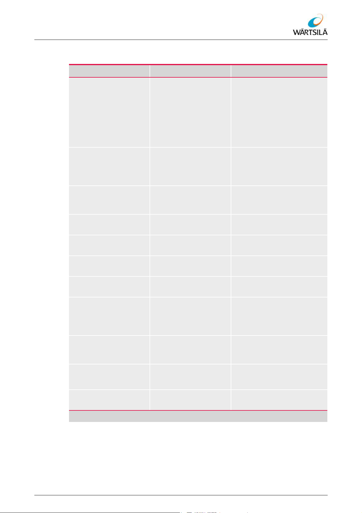
Type of marking Meaning/category Examples
Working instructions Sequences of actions
are divided into working
steps and presented in a
numbered list.
The result of a working
instruction can be given
at the end of the list.
Lists Lists are marked with
bullets.
Arrow symbol () Highlighting of cross-ref-
erences to chapters, sections, tables, charts, etc.
Circled number () for item numbers in fig-
ures and text
Bold type for manufacturers'
names
1. First step of a working instruction.
2. Next step of a working instruction.
– The result of a working in-
struction is marked with
an indent.
• List point A
• List point B
• List point C
... Section 1.3.4...
Remove cover .
Wärtsilä ELAC Nautik GmbH
Italic type for other names and
product designations
Square brackets in bold
for buttons, softkeys, etc. Press the [Enter] button
type [...]
Pointed brackets in bold
type <...>
for keyboard commands,
shortcuts, code numbers, etc.
Pointed bracket in bold
type (arrow right) > and
Presentation of menus or
menu items
bold type
Inverted commas "..." for options, field entries,
designation values
Foot symbol ’ (and backslash \)
for path specification for
file directories
Tab. 1.2: Text Markups
Filter Board EBE 278
Press <STRG>+<ALT>
Press shortcut <F7>
Enter code <N3127.341>
START > MAIN > SUBMENU
Tab "Safety"
Option "cavitation-reduced"
’\\C:\Documents\Windows’
Refer to protection notice ISO 16016
TH 526148001 EN Rev. A 09/2018 Wärtsilä ELAC Nautik GmbH 19 / 134
Page 22

ELAC LAZ5200 – Operating Instructions
About this Document
20 / 134 Wärtsilä ELAC Nautik GmbH TH 526148001 EN Rev. A 09/2018
Refer to protection notice ISO 16016
Page 23
ELAC LAZ5200 – Operating Instructions
Safety
2 Safety
2.1 Preliminary Remark on Chapter "Safety"
Products from Wärtsilä ELAC Nautik GmbH satisfy a high standard of safety. They are
manufactured in accordance with the state of the art and the recognised technical safety
regulations.
Nevertheless, improper use of the product or use for other than the intended purpose can
result in dangers, equipment damage or damage to the environment.
This chapter contains safety-relevant information to help prevent any such dangers.
The safety precautions are structured in a defined manner. See also section 1.6
"Representation Conventions"
2.2 Intended Use
The Navigation Echo Sounder ELAC LAZ 5200 is designed for electro-acoustic vertical
range measurement under water. The distance between the installation location of the
transducer and the sea bed is measured, and hence the depth under keel calculated.
This system may only be installed and operated in accordance with the operating conditions stipulated in the corresponding system and/or device documentation.
Any other or further use does not constitute an intended use. The manufacturer accepts
no liability for any resulting damage; the risks associated with improper use must be
borne solely by the operator.
The intended use also entails:
• Use of the product in accordance with the instructions in the system and/or device
documentation.
• Compliance with the operating, service and maintenance instructions given by the
manufacturer.
2.3 Foreseeable Misuse
It is not permitted to use the Navigation Echo Sounder ELAC LAZ 5200 for the following
purposes.
The Navigation Echo Sounder ELAC LAZ 5200 must not
• be used to disturb or scare away marine species;
• be used in the immediate vicinity of divers or swimmers (particular care must be taken
in port areas and beach regions!);
• be used to interfere with other hydro-acoustic systems (e.g. active and passive sonar
systems, navigation echo sounders, measuring systems, underwater telephone systems);
• only be operated in the defined system configuration;
• operated and/or serviced by unqualified personnel.
Refer to protection notice ISO 16016
TH 526148001 EN Rev. A 09/2018 Wärtsilä ELAC Nautik GmbH 21 / 134
Page 24
ELAC LAZ5200 – Operating Instructions
2.4 Personal Protective Equipment
Personal protective equipment (PPE) must be worn during all work and activities which,
due to their nature, could lead to injuries and health impairment and which cannot be prevented by other measures (technical or organisational).
Personal protective equipment is any device or means intended to be worn or carried by
a person in order to protect this person against a risk or several risks which could endanger the person's health or safety.
Personal protective equipment (PPE) must meet the requirements of the laws and regulations applicable at the place of work.
2.5 System Damage due to Unauthorised Modification
WARNING!
System damage due to unauthorised modification
Modifications and changes to the product or system can result in incalculable risks and
dangers for life and limb.
Only modifications and changes authorised by the manufacturer may be made to the
product or system. Unauthorised modifications are the sole responsibility of the owner and void all liability on the part of the manufacturer.
Safety
This includes also changes to any hardware or software belonging to the system.
22 / 134 Wärtsilä ELAC Nautik GmbH TH 526148001 EN Rev. A 09/2018
Refer to protection notice ISO 16016
Page 25
ELAC LAZ5200 – Operating Instructions
Safety
2.6 Fundamental Safety Precautions
WARNING!
Dangerous electrical voltage!
Improper work on electrical components can result in dangerous electric shocks and in
accidents and falls.
All work on electrical components may only be carried out by qualified electricians.
The electricians must be trained and instructed in the necessary operations such as
earthing, cordoning off and securing the area in which electric voltages may occur.
WARNING!
Danger to operational safety due to improper use
Improper use of the product or use for other than the intended purpose can result in incalculable risks and dangers for life and limb.
The product may only be operated in accordance with its intended use and when it
is in a technically safe condition.
The deactivation or overriding of safety-relevant components, even temporarily and
during maintenance, is not permitted.
Faults that could impair safety must be corrected immediately!
The owner must ensure that no unauthorised persons have access to the product or
system.
WARNING!
Danger to operational safety due to improper maintenance
Improper maintenance work can result in incalculable risks and dangers for life and
limb.
All maintenance work may only be carried out by qualified personnel.
This includes also work on any hardware or software belonging to the system.
NOTICE
Unsuitable spare parts
The use of unauthorised and unsuitable spare parts can lead to damage to the product
and the system.
Use only spare parts corresponding to the technical requirements specified by the
manufacturer. These are only OEM spare parts or spare parts approved by the manufacturer.
The use of unsuitable spare parts will void the manufacturer's liability. Damage re-
sulting from the use of unsuitable spare parts is the sole responsibility of the owner.
Refer to protection notice ISO 16016
TH 526148001 EN Rev. A 09/2018 Wärtsilä ELAC Nautik GmbH 23 / 134
Page 26

2.7 Specific Safety Precautions
2.8 Personnel Qualifications
Personnel group Qualification
Specialist personnel Specialist personnel
• has, thanks to his technical training and experience,
• is sufficiently familiar with the health and safety regu-
Operating personnel Operating personnel
• has been trained in the proper use of the system in a
• performs the intended and necessary operating func-
• is qualified and trained to record abnormalities occur-
ELAC LAZ5200 – Operating Instructions
Safety
adequate knowledge of the work to be carried out;
lations, accident prevention regulations and generally recognised rules of engineering that he can assess
the safe condition of the products described here.
corresponding operators' training course;
tions on the system for the intended use;
ring during operation or test routines and to initiate
the corresponding measures:
– this includes the reporting of abnormalities that
the operator is unable to remedy or assess himself to the responsible maintenance level and/or
superior.
Tab. 2.1: Personnel Qualifications
24 / 134 Wärtsilä ELAC Nautik GmbH TH 526148001 EN Rev. A 09/2018
Refer to protection notice ISO 16016
Page 27

ELAC LAZ5200 – Operating Instructions
Safety
2.9 Obligations of the Owner
The owner is any natural person or legal entity using the product or system, or on whose
behalf the product/system is used. The owner can appoint a deputy/representative to assume and exercise his rights and obligations.
In addition to the owner's obligations arising out of the respective operating regulations,
the owner must also ensure that only persons are allowed to work on or with the product/
system who
• are authorised for this work in accordance with the directives and regulations applicable at the operating location;
• have the appropriate qualifications and permits;
• are familiar with the fundamental regulations on occupational health and safety and
accident prevention, and are trained in the handling of the product/system,
• have read and understood the present documentation and the safety and warning
notes contained in it, and any further applicable documents such as dimensional
drawings and connection plans.
Furthermore the owner is obliged
• to inform the persons working on or with the product/system of any dangers and
emergency situations arising;
• to provide any necessary personal protective equipment for the personnel and to
monitor that the protective equipment is worn;
• to clearly define the spheres of responsibility, competences and supervision of the
personnel;
• to ensure that no external personnel have access to the product or the system;
• to dispose of the product and its components as well as process media correctly in
accordance with the applicable local laws and regulations.
2.10 Requirements for the Workplace
The following regulations applicable at the operating location must be observed:
• The safety and accident prevention regulations
• The national and company-internal regulations
• The regulations on ESD workplaces for all work on electrostatically sensitive components
In addition to these regulations, the following must be observed:
• Personal protective equipment must be used in accordance with the applicable regulations;
• Use only material that is in a faultless condition and suitable tools;
• During transport, installation and maintenance work, use suitable lifting points and lifting and transport equipment designed for the weight of the components;
• During installation and maintenance work, use a sturdy assembly jig in order to be
able to carry out work at a comfortable height;
• Have all materials, tools and measuring equipment available that are necessary for
the work.
Refer to protection notice ISO 16016
TH 526148001 EN Rev. A 09/2018 Wärtsilä ELAC Nautik GmbH 25 / 134
Page 28

ELAC LAZ5200 – Operating Instructions
2.11 Further Regulations to be Observed
In addition to the present documentation, the following rules and regulations must be observed:
• The national and company-internal safety and accident prevention regulations applicable at the operating location
• The recognised technical regulations
• The requirements resulting from any particular features at the place of work
2.12 Disposal and Recycling
2.12.1 Disposal and Recycling
When the product or a component of the product is decommissioned, it must be disposed
of in accordance with the local laws and regulations applicable at the time of disposal.
All parts and materials must be disposed of in such a way that health damage and damage to the environment are ruled out.
Check also which parts and materials can be recycled in order to protect the environment.
Safety
2.12.2 Batteries
Old or defective batteries must be disposed of as special waste in accordance with the
local laws and regulations applicable at the time of disposal.
2.12.3 Electrical and Electronic Scrap
If repair is not possible, defective and replaced electrical and electronic components must
be disposed of as electrical and electronic scrap in accordance with the local laws and
regulations applicable at the time of disposal.
2.12.4 Auxiliary, Process and Cleaning Media
Auxiliary and process media such as oils and greases as well as cleaning agents can
cause considerable damage to health and the environment. They must be disposed of in
accordance with the local laws and regulations applicable at the operating location.
For further information, please refer to the manufacturers' latest safety data sheets and
the respective statutory regulations.
26 / 134 Wärtsilä ELAC Nautik GmbH TH 526148001 EN Rev. A 09/2018
Refer to protection notice ISO 16016
Page 29
ELAC LAZ5200 – Operating Instructions
Technical Description
3 Technical Description
3.1 Functional Description
The Navigation Echo Sounder ELAC LAZ 5200 is designed for electro-acoustic vertical
range measurement under water.
The system measures the distance between the installation location of the transducer
and the sea bed, and hence calculates the depth under keel. The depth information is
calculated from the time between the transmission of a sonar pulse (underwater sound)
and the arrival of the reflected sound waves. The depth data are displayed as an echogram and as a numerical value on the monitor of the Navigation Echo Sounder
ELAC LAZ 5200.
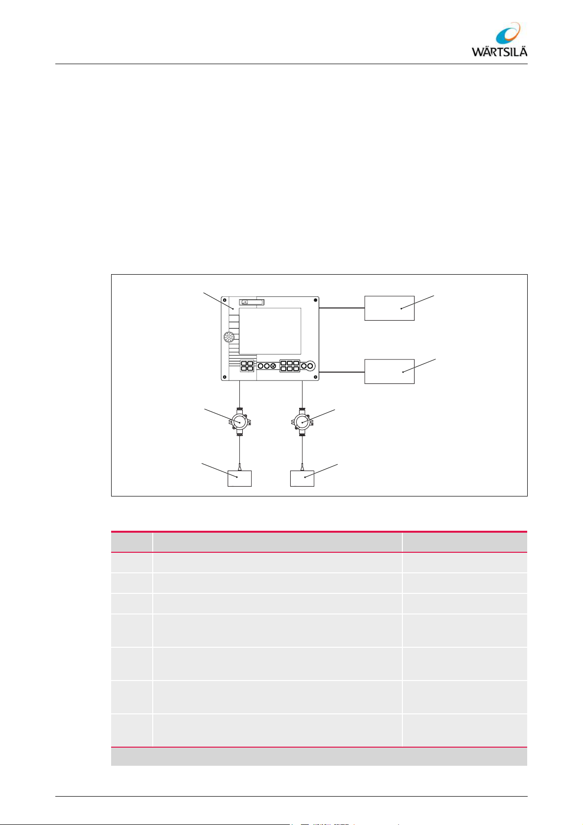
3.2 Component Overview
ELAC LAZ 5200
Fig. 3.1: Component Overview
Item Designation See section
Navigation Echo Sounder ELAC LAZ 5200 3.3.1
Junction Box VK 10 3.3.2
Ultrasonic transducer 3.3.3
Refer to protection notice ISO 16016
TH 526148001 EN Rev. A 09/2018 Wärtsilä ELAC Nautik GmbH 27 / 134
Junction Box VK 10
(optional)
Ultrasonic transducer
(optional)
Slave display
(optional)
Printer
(optional)
Tab. 3.1: Component Overview
3.3.2
3.3.3
3.3.4
3.3.5
Page 30
ELAC LAZ5200 – Operating Instructions
3.3 Description of the Components
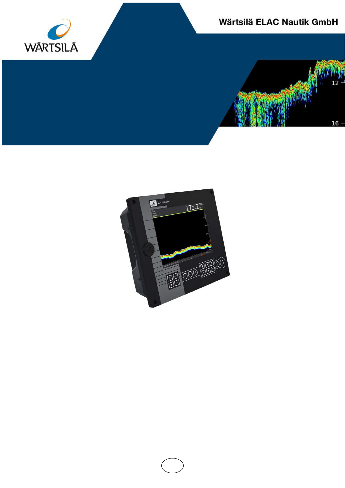
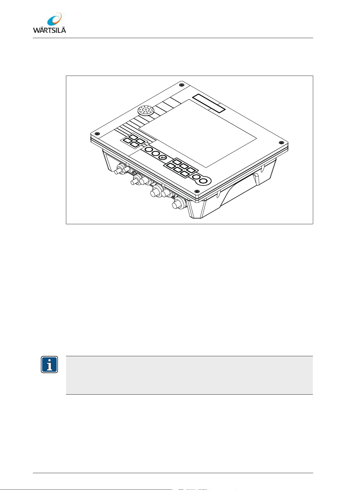
3.3.1 Navigation Echo Sounder ELAC LAZ 5200
Technical Description
Fig. 3.2: Navigation Echo Sounder ELAC LAZ 5200
The Navigation Echo Sounder ELAC LAZ 5200
• is the control and display unit of the system;
• contains a monitor for the display of the data;
• contains a keyboard for operation;
• contains the electronic components for the processing of the transmit, receive and
process signals;
• serves for the input of parameters for the depth measurement;
• serves to save data and to call up recorded data;
• shows the measured values in various selectable representation forms on the display;
• provides the interfaces for connection of the system components.
– Provides further interfaces to additional external components.
– The optional connection of a suitable commercially available printer is possible
(PostScript printer; connection via Ethernet).
When the system is switched off, the integral real-time clock (RTC) is fed by a back-up
battery. When the system is switched on and the voltage of the back-up battery is no
longer sufficient (< 2.4 V), a red LED under X16 (behind the service panel on the rear
of the device) lights up.
28 / 134 Wärtsilä ELAC Nautik GmbH TH 526148001 EN Rev. A 09/2018
Refer to protection notice ISO 16016
Page 31
ELAC LAZ5200 – Operating Instructions
Technical Description
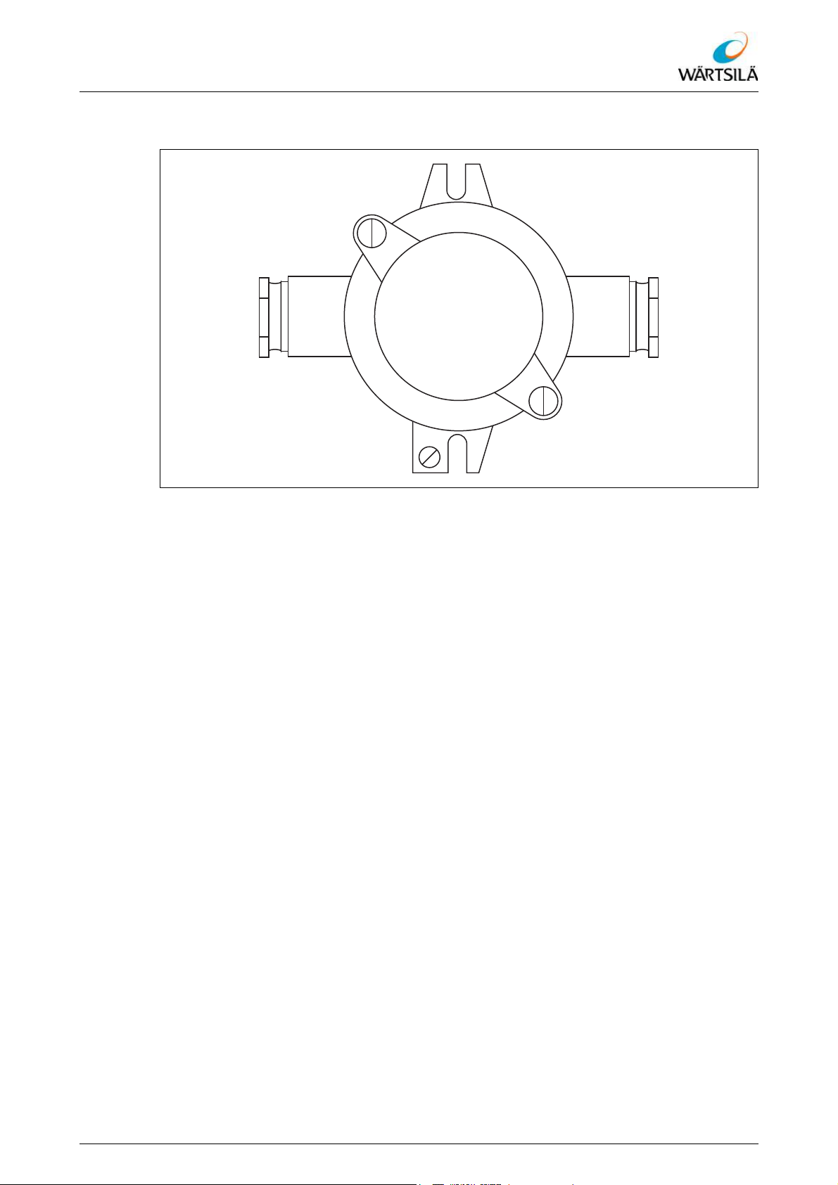
3.3.2 Distribution Box VK 10
Fig. 3.3: Distribution Box VK 10
The Distribution Box VK 10
• serves to connect the ultrasonic transducer to the ship's wiring installation;
Refer to protection notice ISO 16016
TH 526148001 EN Rev. A 09/2018 Wärtsilä ELAC Nautik GmbH 29 / 134
Page 32
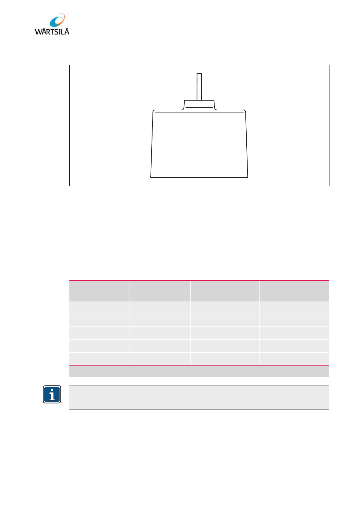
3.3.3 Ultrasonic Transducer
ELAC LAZ5200 – Operating Instructions
Technical Description
Fig. 3.4: Ultrasonic Transducer
The ultrasonic transducer
• is a piezoelectric sonar transducer;
• converts the transmitted electrical energy into acoustic energy and transmits this as
acoustic signals into the water;
• converts the acoustic signals received from the water (echo of the transmitted sound)
into electrical energy that can be analysed electronically;
• is protected by a seawater-resistant filling compound.
The following ultrasonic transducers can be used:
Ultrasonic transducer
Frequency Maximum sound-
ing depth
Max. cable length
LSE 179 15 kHz 6000 m 600 m
LSE 131 30 kHz 2000 m 600 m
LSE 297 50 kHz 600 m 400 m
LSE 329 100 kHz 250 to 300 m 200 m
LSE 313 200 kHz 250 to 300 m 150 m
Tab. 3.2: Overview of Ultrasonic Transducers
The data for the maximum cable length apply to screened cables with a core cross-section of at least 1.5 mm² per core.
30 / 134 Wärtsilä ELAC Nautik GmbH TH 526148001 EN Rev. A 09/2018
Refer to protection notice ISO 16016
Page 33

ELAC LAZ5200 – Operating Instructions
Technical Description
3.3.4 Digital Slave Display (Option)
A compatible digital slave display can be connected to the Navigation Echo Sounder
ELAC LAZ 5200 via an NMEA interface.
3.3.5 Printer (Option)
A PostScript-compatible printer can be connected to the Navigation Echo Sounder
ELAC LAZ 5200 via the network.
3.3.6 Unlocking Tool
Fig. 3.5: Unlocking Tool
The Unlocking Tool
• is used to unlock the female multipoint connectors when disconnecting a connection
cable together with the female multipoint connector from the device;
• is part of the equipment pack supplied.
Refer to protection notice ISO 16016
TH 526148001 EN Rev. A 09/2018 Wärtsilä ELAC Nautik GmbH 31 / 134
Page 34

ELAC LAZ5200 – Operating Instructions
Technical Description
3.4 Technical Data – Navigation Echo Sounder ELAC LAZ 5200
Designation Value
Transducer frequencies 15, 30, 50, 100 and 200 kHz
Depth measuring ranges 0 to 10, 20, 50, 200, 500, 1000, 2000 and
6000 m
Units of measure Metres, fathoms, feet (s
electable)
Measuring precision ± 0.5 % of the respective measuring
range
Measurement resolution 0.5 % of the respective measuring range
Min. measuring depth approx. 1 m below the transducer
Transducer/keel correction 0 to 9.9 m
Draft correction 0 to 99.9 m
Pulse repetition rate up to 300 pulses per minute
Power output selectable, max. 1000 W RMS
Sound velocity 1500 m/s
LAN 100 MBit
Interfaces to IEC 61162-450 and IEC 61162-1
Input protocols GGA, VTG, DDC, ACK
(to IEC 61162-1 (based on NMEA 0183))
Output protocols DPT, DBT, ELAC, ALR
(to IEC 61162-1 (based on NMEA 0183))
BAM data sets ALC, ALF, ACN, HBT
(to IEC 61924-2)
External display and operating unit Open format based on OpenDDS
Data storage 170 hours
Display size 10.4" (800 x 600 pixels), SVGA
Nominal viewing distance from the
display
1m
Compass safe distance
Standard compass
Steering compass
Tab. 3.3: Technical Data – Navigation Echo Sounder ELAC LAZ 5200
0.7 m
0.4 m
Refer to protection notice ISO 16016
32 / 134 Wärtsilä ELAC Nautik GmbH TH 526148001 EN Rev. A 09/2018
Page 35

ELAC LAZ5200 – Operating Instructions
Technical Description
Designation Value
Alarm functions
Shallow water / deep water alarm
Visual alarm
Acoustic alarm
Variable in steps of 1 m
yes, by colour change of the depth display
yes, with muting for 30 seconds
Power supply
Supply voltage
Power consumption
95 to 240 VAC (50/60 Hz)
approx. 35 W
Dimensions (H x W x D) 288 x 336 x 99 mm
Weight 5.5 kg
Protection type IP 53
Environmental conditions
ELAC LAZ 5200
Transducers
protected according to IEC 60945
submerged according to IEC 60945
Temperatures
Operating temperature (recommended)
+20 °C
Operating temperature peaks
Storage temperature (recommended)
Storage temperature peaks
-15 to +55 °C
+20 °C
-20 to +60 °C
Relative humidity ≤ 95 % (permanently)
Tab. 3.3: Technical Data – Navigation Echo Sounder ELAC LAZ 5200
Refer to protection notice ISO 16016
TH 526148001 EN Rev. A 09/2018 Wärtsilä ELAC Nautik GmbH 33 / 134
Page 36

ELAC LAZ5200 – Operating Instructions
Technical Description
34 / 134 Wärtsilä ELAC Nautik GmbH TH 526148001 EN Rev. A 09/2018
Refer to protection notice ISO 16016
Page 37

ELAC LAZ5200 – Operating Instructions
Installation
4 Installation
4.1 Section Safety Messages
Section-specific safety precautions warn of specific dangers which can occur during all
activities described in the following chapter or section. The safety precautions relate to
all the following contents and are given once at the beginning of the chapter or section in
order to avoid repetition.
DANGER!
Hazard to working safety
Unauthorised changes to the system can deactivate the safety devices! Danger to life
and limb!
Only operate the system in accordance with its intended use and in safe and perfect
technical serviceability.
Faults that could impair safety must be corrected immediately!
The locally applicable safety regulations must be strictly observed during all main-
tenance work on the system.
Maintenance work may only be carried out by appropriately qualified personnel.
WARNING!
Danger for persons and machines
Impairment of operational safety by damage and deficiencies of the equipment!
If damage or faults are discovered during maintenance work which cannot be rem-
edied by means of any remedial measures given, switch off the system immediately
and contact the manufacturer's service department.
WARNING!
Dangerous electrical voltage
Missing and improperly performed earthing can result in dangerous electric shocks and
in accidents and falls.
When installing the unit, ensure that all the required earthing connections have been
performed properly.
Never connect the unit to the power supply before all earthing measures have been
completed.
Refer to protection notice ISO 16016
TH 526148001 EN Rev. A 09/2018 Wärtsilä ELAC Nautik GmbH 35 / 134
Page 38

ELAC LAZ5200 – Operating Instructions
Installation
CAUTION!
Risk of injury
Risk of injury and crushing. Pay attention to the weight when handling and transporting
the components. Information on weights can be found in section 3.4 "Technical Data
– Navigation Echo Sounder ELAC LAZ 5200"and/or the further applicable documentation ( 9.1 "Applicable Documents").
Use suitable lifting gear and load lifting appliance!
Pay attention to the centre of gravity!
Do not stand or walk under raised loads!
Use suitable personal protective equipment!
NOTICE
Electrostatically sensitive devices!
Possible destruction of components by electrostatic discharge!
Take the appropriate ESD measures!
NOTICE
Corrosion damage possible
All components must be included in the ship's anodic corrosion protection system.
The design of the corrosion protection system (e.g. positioning and design of the
sacrificial anodes) must be carried out by the shipyard.
NOTICE
Damage to the transducers possible
Improper handling of the transducers during installation can result in material damage.
Avoid collisions with the transducer housing.
Avoid collisions with the transducer transmitting surface and avoid damage caused
by scratches.
Ensure that all parts of the transducers remain free from oil and grease.
Do not coat the transducer transmitting surface with paints or lacquers or cover in
any other way (adhesive tape. etc.).
Damage to the antifouling coating must be repaired in accordance with the manu-
facturer’s instructions.
NOTICE
Damage to the transducer cables possible
Improper handling of the transducer cables can result in damage.
Do not lift or transport the transducers at the cable.
36 / 134 Wärtsilä ELAC Nautik GmbH TH 526148001 EN Rev. A 09/2018
Refer to protection notice ISO 16016
Page 39
ELAC LAZ5200 – Operating Instructions
Installation
NOTICE
Damage to the cables possible.
Failure to observe the admissible bending radii can result in damage to the connection
cables.
Observe the admissible bending radii during all cable connection and laying work.
NOTICE
Loosening of screws possible
Vibration and impact loads can cause screws and threaded joints to come loose.
Secure all bolted connections with medium-strength bolt locking compound (e.g.
Loctite 243) during installation.
4.2 Preparation for Installation
4.2.1 General Information on Cable Laying
When laying the cables, adhere to the following requirements:
• Observe the minimum bending radii of the connection cables according to the dimensional drawings ( 9.1 "Applicable Documents").
• Take care not to damage the cable sheath when using cable ties.
• Do not fasten the connection cables using metal cable ties.
• Do not lay the connection cables over sharp corners and edges.
• Strain relief of the connection cables must be ensured by the shipyard.
• Transducer cables must be laid at a distance of at least 0.5 m to other cables.
• The transducer cable from the transducer to the distribution box must be laid in a steel
conduit.
• A double sheathed cable is used as connection cable from the distribution box to the
echo sounder. The inner cable sheath is connected at one end to the grounding terminal of the echo sounder, the outer cable sheath at both ends to the ship’s earth.
• Sheathed cables must be used over the whole length between the transducer and the
echo sounder. All distribution boxes must be made of metal.
Refer to protection notice ISO 16016
TH 526148001 EN Rev. A 09/2018 Wärtsilä ELAC Nautik GmbH 37 / 134
Page 40

ELAC LAZ5200 – Operating Instructions
4.2.2 General Information on Transducer Installation
The system operates acoustically. Acoustic noise in the vicinity of the transducers reduces the sensitivity and performance of the system.
The following list of frequent sources of interference can serve as a guide for finding the
ideal installation location in the form of the best compromise between different sources:
• Air bubbles under the transducer:
– Air bubbles mean additional noise and are very strong acoustic reflectors. Bub-
bles can be generated by flow dynamic processes under the ship by the bow wave
or the bow thruster, or they are trapped under the ship. The location chosen for
the transducer must ensure that air bubbles are avoided.
• Turbulent water flows:
– A turbulent water flow can occur for various reasons. In order to reduce noise in
the system caused by turbulence, the area in front of the transducers must be
smooth and free of obstacles. This applies e.g. to protruding parts such as zinc
anodes, safety straps, sonar expansion units or anchor openings.
• Structure-borne noise:
– All machinery running inside the ship generates structure-borne noise. If this noise
finds its way to the transducer, the receiver may be flooded. Heavy machinery
should not be operated in the immediate vicinity of the transducers. This includes
i.a. generators, pumps, separators and motors.
• Bow thruster:
– During operation, a bow thruster often generates so much noise and so many bub-
bles that echo sounder operation is no longer possible. On ships with bow thruster,
transducers must be installed ahead of the bow thruster.
• Bulbous bow
– A bulbous bow generates a large number of air bubbles that hinder echo sounder
operation. On ships with bulbous bow, transducers must be installed as far forward as possible.
• Other sonars or echo sounders
– To avoid mutual interferences, it must be ensured during installation and configu-
ration (in particular during transducer selection) that no other sonars or echo
sounders use the frequencies of the Navigation Echo Sounder ELAC LAZ 5200.
Installation
4.2.3 Earthing
Components must be earthed to satisfy the EMC requirements and to protect the personnel from electric shocks.
Each unit has an earthing terminal marked with the earth symbol. Refer to the dimensional drawing for the location of this earthing terminal.
Each unit must have an electrically conductive connection to the ship’s earth by the shortest route using a cable with a minimum diameter of 6 mm
2
. This connection must ensure
a uniform and good connection at all times.
Make the earth connection as follows:
38 / 134 Wärtsilä ELAC Nautik GmbH TH 526148001 EN Rev. A 09/2018
Refer to protection notice ISO 16016
Page 41

ELAC LAZ5200 – Operating Instructions
Installation
1. The earth connection requires clean metallic surfaces. If necessary, remove any
paint or other non-conductive materials from the earthing terminal.
Fig. 4.1: Earthing
2. Wipe all mounting surfaces with residue-free cleaning solution to ensure that these
are clean and free from paint flakes, metal chips and other residues.
3. Apply a thin film of lubricant with corrosion inhibiting properties (e.g. zinc dust/Vase-
line mixture) to the cleaned area of the mounting surfaces and the threads of all parts
(nuts and bolts).
4. Clip earthing cable clamp to earthing stud on the clean metal surface .
5. Place washer onto the earthing stud.
6. Place spring lock washer onto the earthing stud.
7. Screw hexagon nut onto the earthing stud and tighten.
8. Measure the resistance between the housing of the unit and the PE conductor/ship’s
hull using a multimeter. It must not exceed 0.3 Ohm.
Star earthing with busbars insulated from the ship’s hull is not permitted.
If the transducer cable is laid in a conduit, each individual conduit section must be earthed
at both ends.
Please contact the manufacturer if the demanded earthing measures cannot be applied.
Earthing test:
The minimum cross-section of the earthing cable/earthing strap is 6 mm².
Earthing cables/straps are fitted with toothed lock washers at both ends.
The resistance between the housing of the unit and the PE conductor/ship’s hull is ≤ 0.3
Ohm.
Refer to protection notice ISO 16016
TH 526148001 EN Rev. A 09/2018 Wärtsilä ELAC Nautik GmbH 39 / 134
Page 42

ELAC LAZ5200 – Operating Instructions
4.3 Description of the Installation Work
4.3.1 Installation of Navigation Echo Sounder ELAC LAZ 5200
The Navigation Echo Sounder ELAC LAZ 5200 can be installed in one of the following
ways:
• Rail mounting
• Panel installation
• Table mounting
• Suspension from the ceiling
The Navigation Echo Sounder ELAC LAZ 5200 is intended for bridge installation.
Proceed as follows to install the Navigation Echo Sounder ELAC LAZ 5200::
1. Install the Navigation Echo Sounder ELAC LAZ 5200 at the installation location as
shown in the installation drawing ( 9.1 "Applicable Documents").
Installation
WARNING!
Dangerous electrical voltage
Missing and improperly performed earthing can result in dangerous electric shocks and
in accidents and falls.
When installing the unit, ensure that all the required earthing connections have been
performed properly.
Never connect the unit to the power supply before all earthing measures have been
completed.
4.3.2 Installation of Transducer
Precondition:
The preconditions for the transducer installation described in section 4.2.2 have
been observed when selecting the installation location.
Proceed as follows to install the transducer:
CAUTION!
Dangerous electrical voltage
Risk of electric shock from piezoelectric charge at the socket of the transducer. Piezoelectric charges result from mechanical force acting on the transducer or extreme fluctuations in temperature.
Do not touch the contacts of the socket.
Fit a protective cap to the socket or short-circuit immediately after removing the con-
nector.
1. Install the transducer at the installation location as described in the installation in-
structions and shown in the installation drawing ( 9.1 "Applicable Documents").
40 / 134 Wärtsilä ELAC Nautik GmbH TH 526148001 EN Rev. A 09/2018
Refer to protection notice ISO 16016
Page 43
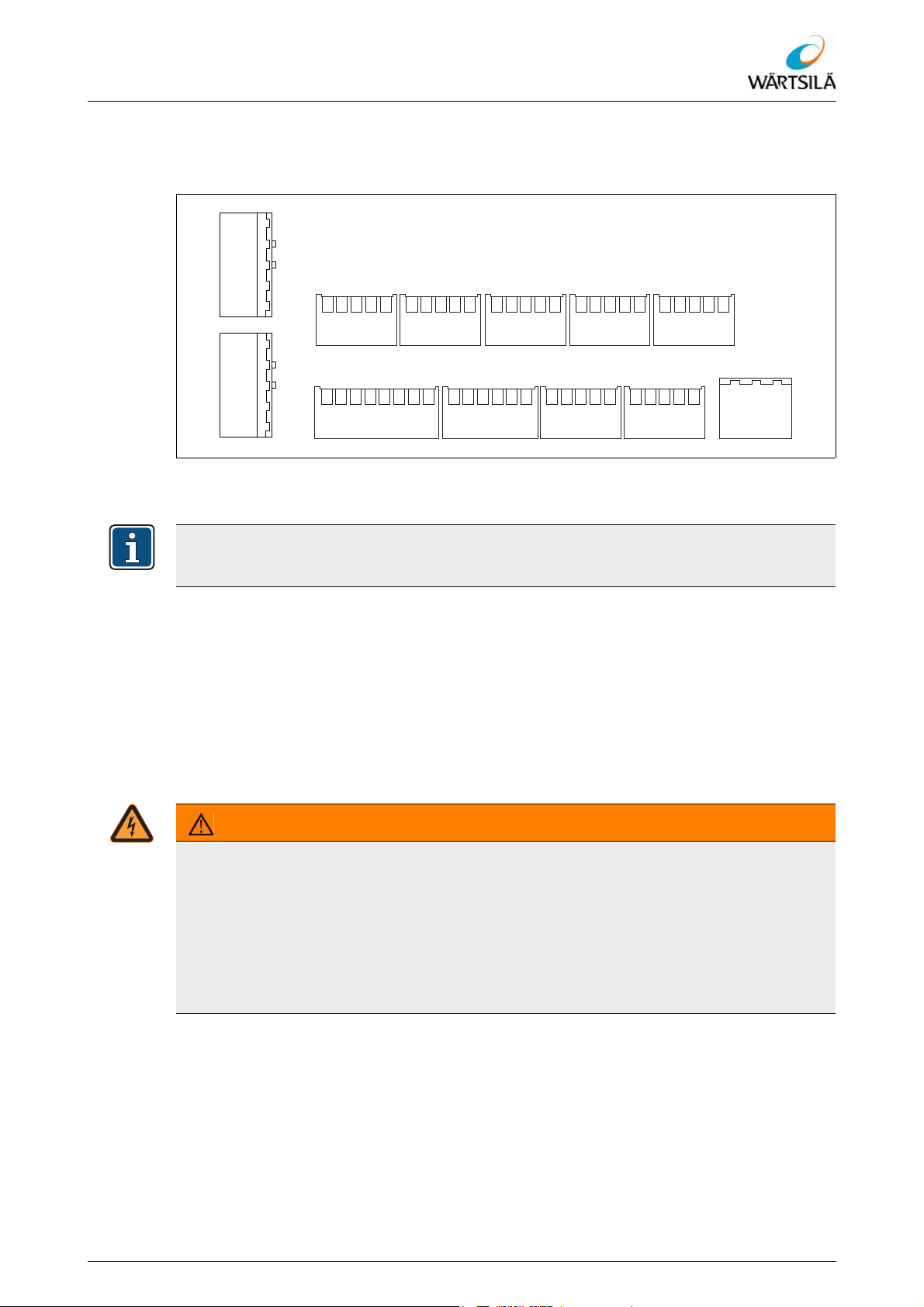
ELAC LAZ5200 – Operating Instructions
Installation
4.3.3 Installation of Navigation Echo Sounder ELAC LAZ 5200 Connection Cable
4.3.3.1 Overview Pin Assignment Navigation Echo Sounder ELAC LAZ 5200
1234512345
TX2+
TX2+
GND
X12
TRANSD 1 TRANSD 2
X11
TX2-
TX2-
TX1+
TX1+
GND
TX1-
TX1-
GND
TX1-(A)
TX1+(B)
RS422-1 RS422-3 RS422-4 ETHERNET
OFC-2
GND
GND
MUTE/OFC
TX2-(A)
GND
RX2-(A)
TX2+(B)
RX1+(B)
RX1-(A)
12345
RS422-2
X5 X6 X7 X8 X9
M-OUT-2
M-OUT-1
OFC-1
M-IN-2
12345123451234512345
M-IN-1
GND
ALARM BLK/KEY REMOTE
TX3+(B)
TX3-(A)
RX2+(B)
IF-NO
IF-NC
RX3-(A)
RX3+(B)
GND
PSPLY-1
IF-COM
PSPLY-2
TX4-(A)
GND
TX4+(B)
BLANK-
BLANK+
KEY+
GND
KEY-
X15X14X13
GND
RX4+(B)
RX4-(A)
OFF-1
GND
OFF-2
Fig. 4.2: Overview Pin Assignment Navigation Echo Sounder ELAC LAZ 5200
4.3.3.2 Installation of Navigation Echo Sounder ELAC LAZ 5200 Connection Cable
DA+
DA-
DB-
DB+
NEUTR
ON-2
123451234512345667812345
X16 X3
PHASE
ON-1
HV-PWR
PE
123
One example of the connection of a connection cable is described below. Connect all
other connection cables in the manner described.
Preconditions:
The Navigation Echo Sounder ELAC LAZ 5200 is installed 4.3.1.
The transducers are installed 4.3.2.
The transducer configuration has been performed at the Navigation Echo Sounder
ELAC LAZ 5200 5.
Proceed as follows to connect the connection cables to the Navigation Echo Sounder
ELAC LAZ 5200::
WARNING!
Dangerous electrical voltage
Missing and improperly performed earthing can result in dangerous electric shocks and
in accidents and falls.
When installing the unit, ensure that all the required earthing connections have been
performed properly.
Never connect the unit to the power supply before all earthing measures have been
completed.
Refer to protection notice ISO 16016
TH 526148001 EN Rev. A 09/2018 Wärtsilä ELAC Nautik GmbH 41 / 134
Page 44

ELAC LAZ5200 – Operating Instructions
Installation
WARNING!
Possible risk of electrical shock due to unexpected switching on
The device can switch itself on unexpectedly if a corresponding signal is sent via the
lines X16/1 and X16/2 (Remote ON) (see interconnection diagram of the Navigation
Echo Sounder ELAC LAZ 5200 9.1 "Applicable Documents"). This can result in dan-
gerous electric shocks and other injuries.
Before connecting the lines X16/1 and X16/2, ensure that the device is disconnected
from the power supply.
When installing the connection cables, connect the connection cable for the power
supply (cable gland X1) last.
1. Remove the service panel on the rear of the device:
1.1. Loosen and remove the mounting bolts (6 pcs.) of the service panel.
1.2. Carefully lift the service panel until the connection of the earthing conductor
on the service panel can be reached.
1.3. Disconnect the earthing conductor.
1.4. Remove the service panel.
Fig. 4.3: Installation of the Connection Cables
2. Identify the cable gland for the connection cable to be connected using the con-
nection plan ( 9.1 "Applicable Documents").
3. Loosen the threaded bush of the cable gland.
4. Remove the plug from the cable gland.
5. Prepare the connection cable for connection:
42 / 134 Wärtsilä ELAC Nautik GmbH TH 526148001 EN Rev. A 09/2018
Refer to protection notice ISO 16016
Page 45

ELAC LAZ5200 – Operating Instructions
Installation
5.1. Remove the outer sheath, cable shield and inner sheath of the connection cable from the cores as far as needed to ensure the length of the exposed cores
is sufficient for connection.
5.2. Remove the insulation from the core ends as far as needed to ensure safe
electrical contact with the terminals.
6. Thread the connection cable through the cable gland into the Navigation Echo
Sounder ELAC LAZ 5200.
– The outer sheath of the connection cable must be in contact with the spring con-
tacts of the cable gland.
– The outer sheath of the connection cable must be surrounded by the rubber seal
of the cable gland.
7. Tighten the threaded bush of the cable gland.
7.1. Use the (optional) installation tools supplied, if necessary.
7.2. Pay attention that the connection cable does not slip in the cable gland.
8. Connect the conductors of the connection cable to the terminals according to the
pin assignment 4.3.3.1 and the cable connection list ( 9.1 "Applicable
Documents").
8.1. Use the corresponding push-button to open the clamping point.
9. Attach the cable sign supplied to the connection cable according to the cable gland.
10. Install the service panel:
10.1. Position the service panel at the installation location in such a way that the
connection of the earthing conductor on the service panel can be reached.
10.2. Connect the earthing conductor.
10.3. Position the service panel at the installation location.
10.4. Screw in and tighten the mounting bolts (6 pcs.) of the service panel.
Refer to protection notice ISO 16016
TH 526148001 EN Rev. A 09/2018 Wärtsilä ELAC Nautik GmbH 43 / 134
Page 46

ELAC LAZ5200 – Operating Instructions
Installation
44 / 134 Wärtsilä ELAC Nautik GmbH TH 526148001 EN Rev. A 09/2018
Refer to protection notice ISO 16016
Page 47

ELAC LAZ5200 – Operating Instructions
Commissioning (Configuration)
5 Commissioning (Configuration)
After installation of the system components, the system has to be configured. The system
is configured with the transducers not yet connected.
Carry out commissioning (configuration)
Preconditions:
The system components are installed 4.
All connections except the transducer connections have been made.
Proceed as follows to carry out commissioning:
NOTICE
Damage to the transducers possible
When the device is switched on and the transducers are configured, the device continuously transmits signals. Transmitting of signals with the wrong transducer configuration can result in damage to the transducers and the device.
When configuring the transducer channels, ensure that the correct transducer model
is selected.
Only use the device with the correct transducer configuration.
1. Switch on the Navigation Echo Sounder ELAC LAZ 5200 6.5.2.
WARNING!
Unauthorised changes can result in very serious injury or even death.
Unauthorised modification of the configuration parameters can endanger the safety of
the ship and result in very serious injury or even death.
Changes to the configuration parameters may only be made by qualified personnel.
Do not change the configuration parameters after commissioning unless changes
have been made to the system (e.g. changing of the transducer model).
2. Configure the transducer channels 6.5.11.1.
3. Configure the network settings for the Navigation Echo Sounder ELAC LAZ 5200
6.5.11.2.
4. If installed, configure the network settings for the printer 6.5.11.3.
5. Configure the existing interfaces 6.5.11.5.
6. Set the draft of the ship 6.5.11.6.
7. Set the date and time 6.5.11.7.
8. Check the alarm settings and modify, if necessary 6.5.6.
9. Test the depth alarm 6.5.6.3.
9.1. Check whether the test alarm is displayed via the interfaces according to the
Refer to protection notice ISO 16016
interface configuration.
10. Switch off the Navigation Echo Sounder ELAC LAZ 5200 6.5.3.
TH 526148001 EN Rev. A 09/2018 Wärtsilä ELAC Nautik GmbH 45 / 134
Page 48

ELAC LAZ5200 – Operating Instructions
Commissioning (Configuration)
46 / 134 Wärtsilä ELAC Nautik GmbH TH 526148001 EN Rev. A 09/2018
Refer to protection notice ISO 16016
Page 49

ELAC LAZ5200 – Operating Instructions
Operation
6 Operation
6.1 Section Safety Messages
Section-specific safety precautions warn of specific dangers which can occur during all
activities described in the following chapter or section. The safety precautions relate to
all the following contents and are given once at the beginning of the chapter or section in
order to avoid repetition.
CAUTION!
Possible danger from acoustic energy
In transmission mode, acoustic energy is transmitted through the water. This can represent a hazard for divers and marine species.
Do not activate the system in the immediate vicinity of divers or swimmers.
Do not use the system to disturb or scare away marine species.
NOTICE
Damage to the transducers possible!
The output of a transmission signal against air can result in damage to the connected
transducers.
The system may only be activated when the transducers are completely immersed
in water.
NOTICE
Damage to the transducers possible!
As soon as the device is switched on, it transmits signals continuously. Transmitting of
signals with the wrong transducer configuration can result in damage to the transducers
and the device.
Connect the transducers to the system only after configuration.
Carry out changes to the transducer configuration only with the transducers discon-
nected from the system.
Observe the fundamental safety-relevant information in chapter "Safety" ( 2)!
Operator errors possible!
The system may only be operated by trained and qualified personnel.
Refer to protection notice ISO 16016
TH 526148001 EN Rev. A 09/2018 Wärtsilä ELAC Nautik GmbH 47 / 134
Page 50

ELAC LAZ5200 – Operating Instructions
Operation
6.2 Operating and Display Elements
6.2.1 Overview – Operating and Display Elements of Navigation Echo Sounder ELAC LAZ 5200
ELAC LAZ 5200
CURSOR
ESCAPE
ENTER
PRINT
MARKER
GAIN
RANGE DIM
OFF ON
Fig. 6.1: Operating and Display Elements of Navigation Echo Sounder ELAC LAZ 5200
Item Designation See section
Display ---
Keyboard 6.2.2
Tab. 6.1: Operating and Display Elements of Navigation Echo Sounder ELAC LAZ 5200
48 / 134 Wärtsilä ELAC Nautik GmbH TH 526148001 EN Rev. A 09/2018
Refer to protection notice ISO 16016
Page 51

ELAC LAZ5200 – Operating Instructions
ENTER
ESCAPE
CURSOR
PRINT
GAIN
MARKER
RANGE DIM
OFF ON
Operation
6.2.2 Keyboard
Item Designation See section
[CURSOR] keys 6.2.3.1
[ESCAPE] key 6.2.3.2
[ENTER] key 6.2.3.2
Fig. 6.2: Keyboard
[PRINT] key 6.2.3.3
[MARKER] key 6.2.3.4
Confirmation key 6.2.3.5
[GAIN] keys 6.2.3.6
[RANGE] keys 6.2.3.7
[DIM] keys 6.2.3.8
[OFF] key 6.2.3.9
[ON] key 6.2.3.9
Tab. 6.2: Keyboard
Refer to protection notice ISO 16016
TH 526148001 EN Rev. A 09/2018 Wärtsilä ELAC Nautik GmbH 49 / 134
Page 52

ELAC LAZ5200 – Operating Instructions
CURSOR
ENTER
ESCAPE
PRINT
MARKER
6.2.3 Description of the Operating and Display Elements
6.2.3.1 [CURSOR] Keys
The [CURSOR] keys
• are used to navigate within the menu.
• are used to change parameters.
6.2.3.2 [ESCAPE] Key and [ENTER] Key
The [ESCAPE] key
• is used to close a menu, to abort parameter changes and to close the history.
Operation
Fig. 6.3: [CURSOR] Keys
The [ENTER] key
• is used to open menus, to activate or
deactivate menu items and to confirm
parameter changes.
6.2.3.3 [PRINT] Key
The [PRINT] key
• is used to print the current screen display.
A corresponding network printer must be configured to allow the current screen display
to be printed.
6.2.3.4 [MARKER] Key
The [MARKER] key
• is used to mark a point in time within the
echo sounder mask.
– When the [MARKER] key is
pressed, a white marking line appears that runs vertically through the
echo sounder mask.
Fig. 6.4: [ESCAPE] Key and [ENTER] Key
Fig. 6.5: [PRINT] Key
Fig. 6.6: [MARKER] Key
Marking lines are saved in the history ( 6.5.8 "“History” View").
Refer to protection notice ISO 16016
50 / 134 Wärtsilä ELAC Nautik GmbH TH 526148001 EN Rev. A 09/2018
Page 53
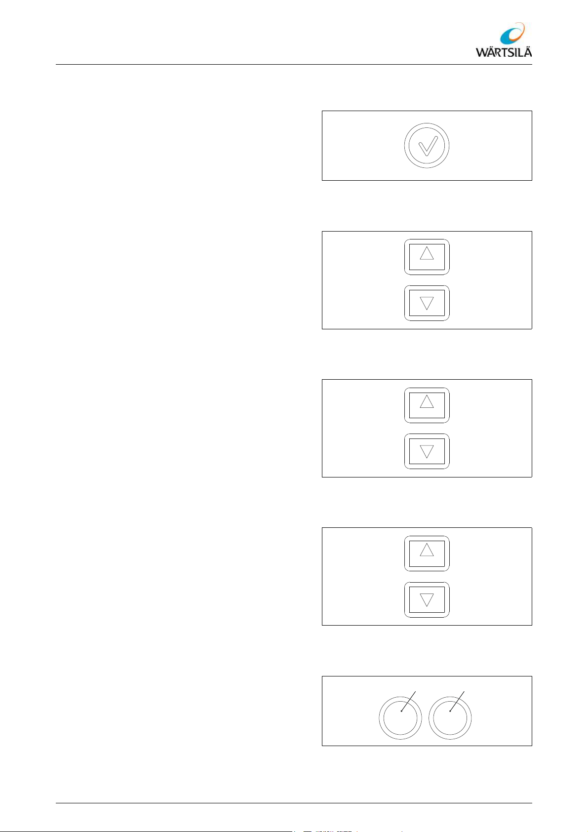
ELAC LAZ5200 – Operating Instructions
GAIN
RANGE
DIM
Operation
6.2.3.5 Confirmation Key
The confirmation key
• is used to confirm alarms.
6.2.3.6 [GAIN] Keys
The [GAIN] keys
• are used for manual setting of the reception gain:
– Pressing the UP key increases the
reception gain.
– Pressing the DOWN key decreases
the reception gain.
Fig. 6.7: Confirmation Key
6.2.3.7 [RANGE] Keys
The [RANGE] keys
• are used to set the depth measuring
range:
– Pressing the UP key decreases the
depth measuring range.
– Pressing the DOWN key increases
the depth measuring range.
6.2.3.8 [DIM] Keys
The [DIM] keys
• are used to adjust the background lighting of the display and keyboard:
– Pressing the UP key increases the
brightness.
– Pressing the DOWN key decreases
the brightness.
Fig. 6.8: [GAIN] Keys
Fig. 6.9: [RANGE] Keys
Fig. 6.10: [DIM] Keys
6.2.3.9 [ON] Key and [OFF] Key
The [OFF] key
• is used to switch off the device.
The [ON] key
Refer to protection notice ISO 16016
TH 526148001 EN Rev. A 09/2018 Wärtsilä ELAC Nautik GmbH 51 / 134
• is used to switch on the device.
Fig. 6.11: [ON] Key and [OFF] Key
OFF ON
Page 54

6.3 Graphical User Interface
6.3.1 Graphical User Interface – Overview
ELAC LAZ5200 – Operating Instructions
Operation
Fig. 6.12: Graphical User Interface
Item Designation See section
Information field 6.3.2.1
Display area 6.3.2.2
Status bar 6.3.2.3
Menu 6.4.1
Tab. 6.3: Graphical User Interface
When using two transducers, the appearance of the information field and display area
depends on the number of active channels. If only one channel is active, the whole
screen width is used to display the information on this channel. If two channels are active, the information field and display area are split and the information on the two channels is displayed alongside one another.
52 / 134 Wärtsilä ELAC Nautik GmbH TH 526148001 EN Rev. A 09/2018
Refer to protection notice ISO 16016
Page 55
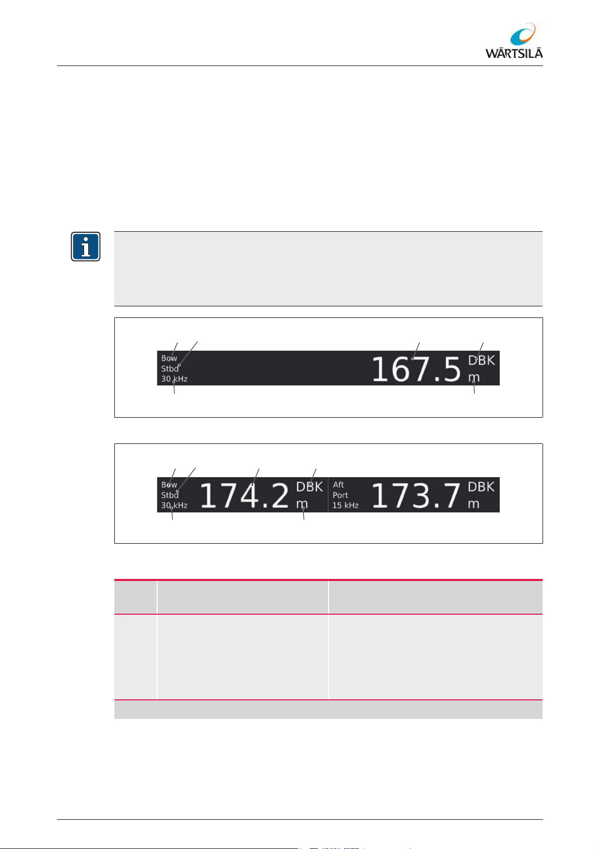
ELAC LAZ5200 – Operating Instructions
Operation
6.3.2 Elements of the User Interface
6.3.2.1 Information Field
The information field contains the digital depth display of the Navigation Echo Sounder
ELAC LAZ 5200, as well as information on the transducer and the measuring parameters
for the depth measurement.
The appearance of the information field depends on the number of active channels. If
only one channel is active, the whole width is used to display the information on this channel (Fig. 6.13). If two channels are active (optional), the information field is split and
the information on the two channels is displayed alongside one another (Fig. 6.14).
On systems with two channels, the active channels can be selected in the menu under
MAIN MENU > SETTINGS > Active Channel ( 6.5.5.5 "Selecting the Active
Channels").
On systems with only one channel, the corresponding menu item is not displayed.
Fig. 6.13: Information Field (1-channel operation)
Fig. 6.14: Information Field (2-channel operation)
Item Designation
Transducer position (longitudinal
direction)
Description/
see section
Display of the installation position in longitudinal direction
•Bow
• Midship
•Aft
Tab. 6.4: Information Field
Refer to protection notice ISO 16016
TH 526148001 EN Rev. A 09/2018 Wärtsilä ELAC Nautik GmbH 53 / 134
Page 56

ELAC LAZ5200 – Operating Instructions
Operation
Item Designation
Description/
see section
Display of the installation position in transverse direction
Transducer position (transverse
direction)
• Starboard
•Center
•Port
Digital display of the measured depth
Digital depth display
The colour of the figures indicates the reliability of the displayed value
(Table 6.5)
Display of the reference point
Reference point
• DBK (Depth Below Keel)
• DBT (Depth Below Transducer)
• DBS (Depth Below Surface)
Unit of measure Display of the unit of measure (m, ft, fm)
Frequency Display of the frequency
Tab. 6.4: Information Field
The reliability of the measured value in the digital depth display is indicated by different
colours:
Display Description
White figures = Valid depth, high reliability
Yellow figures and yellow question mark =
Uncertain depth, low reliability
Yellow question mark = Invalid depth, sea
bed not found
Tab. 6.5: Reliability of the Depth Display
54 / 134 Wärtsilä ELAC Nautik GmbH TH 526148001 EN Rev. A 09/2018
Refer to protection notice ISO 16016
Page 57

ELAC LAZ5200 – Operating Instructions
Operation
6.3.2.2 Display Area
Fig. 6.15: Display Area (1-Channel Operation)
The display area is used for the visual display of the echo and sensor data. The appearance of the display area depends on the number of active channels. If only one channel is active, the whole width is used to display the echo for this channel (Fig. 6.15).
Fig. 6.16: Display Area (2-Channel Operation)
If two channels are active (optional), the display area is split and the echoes of both channels are displayed alongside one another (Fig. 6.16).
Refer to protection notice ISO 16016
On systems with two channels, the active channels can be selected in the menu under
MAIN MENU > SETTINGS > Active Channel ( 6.5.5.5 "Selecting the Active
Channels").
On systems with only one channel, the corresponding menu item is not displayed.
TH 526148001 EN Rev. A 09/2018 Wärtsilä ELAC Nautik GmbH 55 / 134
Page 58
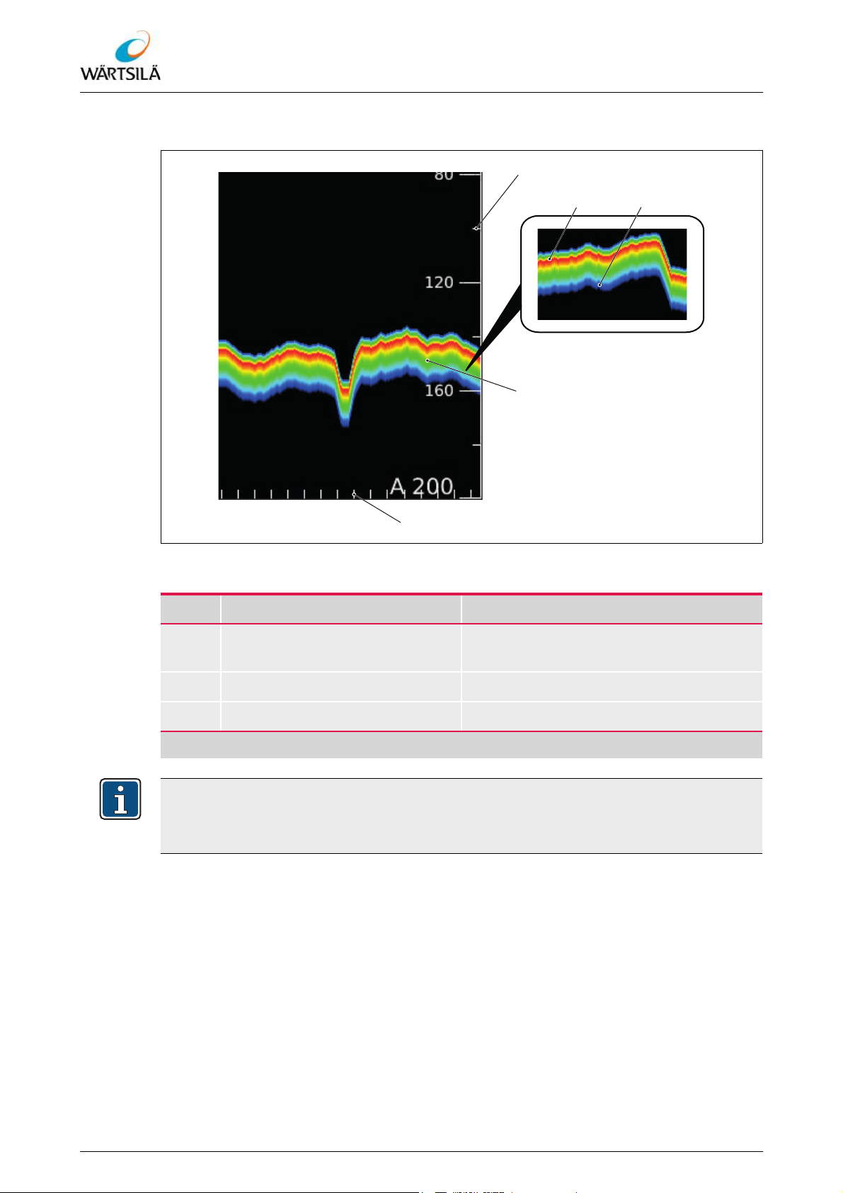
6.3.2.2.1 Representation of the Echo
ELAC LAZ5200 – Operating Instructions
Operation
Fig. 6.17: Representation of the Echo
Item Designation Description
Scale of the depth measuring
range
Display of the depth in the selected unit
Echo Graphic representation of the echo
Time scale Time marks at intervals of one minute
Tab. 6.6: Representation of the Echo
The time marks are dependent on the system time and the set depth measuring range.
If the time is changed or the depth measuring range changes, the distances between
the time marks may vary.
The quality of the echo is represented with a colour scale. The displayed colour varies,
depending on the condition of the sea bed.
• The strongest echo is displayed in red .
• The weakest echo is displayed in blue .
56 / 134 Wärtsilä ELAC Nautik GmbH TH 526148001 EN Rev. A 09/2018
Refer to protection notice ISO 16016
Page 59
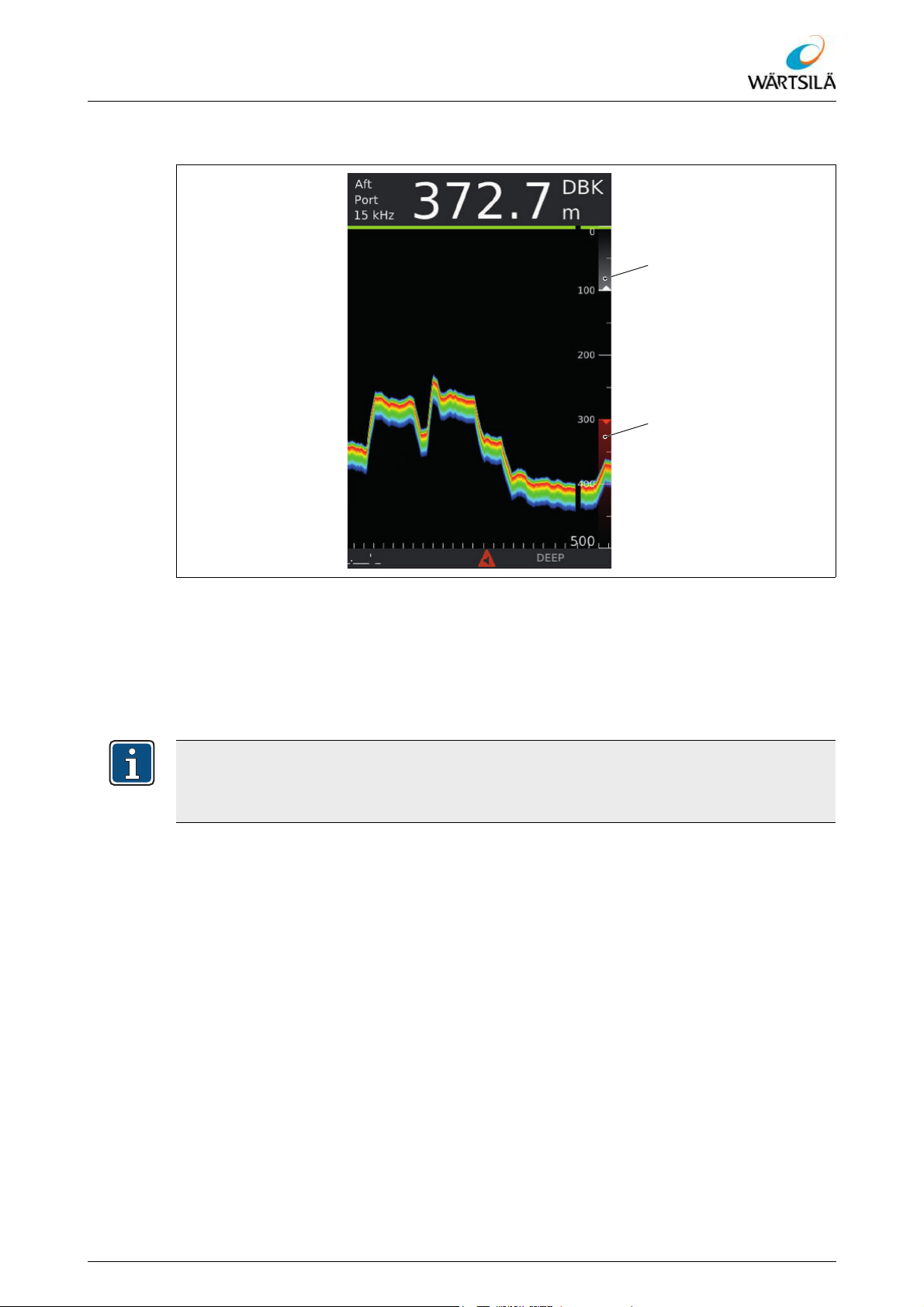
ELAC LAZ5200 – Operating Instructions
Operation
6.3.2.2.2 Representation of Alarm Limits
Fig. 6.18: Alarm Limits in the Display Area
The set alarm limits are shown in the display area as white marks on the scale of the
depth measuring range. The marks have an arrow tip. In the case of a shallow water
alarm, the tip of the arrow points upwards; in the case of a deep water alarm, the tip of
the arrow points downwards.
If an alarm limit is overrun, the corresponding mark turns red .
The alarm limits are only displayed when the corresponding alarm is active. A description of activation and deactivation of alarms can be found in section 6.5.6.1. A description of setting the alarm limits can be found in section 6.5.6.2.
Refer to protection notice ISO 16016
TH 526148001 EN Rev. A 09/2018 Wärtsilä ELAC Nautik GmbH 57 / 134
Page 60

6.3.2.3 Status Bar
ELAC LAZ5200 – Operating Instructions
Operation
Fig. 6.19: Status Bar
Item Designation
Description/
see section
Display of the data in format
Date
"yyyy-mm-dd"
6.5.11.7 "Setting of the Date and Time"
Display of the time (UTC) in format
Time
"hh:mm:ss UTC"
6.5.11.7 "Setting of the Date and Time"
Position Display of the position
Indicates that NON-IMO mode is active
NON-IMO
6.3.2.4 "Description of NON-IMO
Mode"
Display of the depth alarm
Alarm message
6.3.2.5 "Description of the Depth
Alarm"
Tab. 6.7: Status Bar
In the event of a failure of the internal data flow, "____-__-__ --:--:-- UTC" is displayed
instead of the date and time.
Possible causes of the failure of the internal data flow and possibilities for remedying
the fault can be found in section 7 "Troubleshooting and Remedy".
In the event of a failure of the GPS data,
"__° __.__’ _ __° __.__’ _" is displayed instead of the position.
Possible causes of the failure of the GPS data and possibilities for remedying the fault
can be found in section 7 "Troubleshooting and Remedy".
58 / 134 Wärtsilä ELAC Nautik GmbH TH 526148001 EN Rev. A 09/2018
Refer to protection notice ISO 16016
Page 61

ELAC LAZ5200 – Operating Instructions
Operation
6.3.2.4 Description of NON-IMO Mode
NON-IMO mode is active if only a non-approved transducer (LSE 179) is in use. When
NON-IMO mode is active, a corresponding message is displayed in the status bar
6.3.2.3.
In NON-IMO mode, the depth information in NMEA data set DPT 9.3.8 is not complet-
ed. In this case, the NMEA data set PELASDS 9.3.12 can be used, as this data set
provides a depth value even with non-approved transducers.
If, in 2-channel mode (optional), both an approved transducer and a non-approved
transducer are used, NON-IMO mode is only active when only the channel of the nonapproved transducer is selected as active channel ( 6.5.5.5 "Selecting the Active
Channels"). If only the channel of the approved transducer is selected, or both transducers are selected, NON-IMO mode is deactivated.
6.3.2.5 Description of the Depth Alarm
The depth alarm can be triggered for both shallow and deep water. When the alarm function is active, the depth alarm is triggered when the set alarm limit is overrun.
When an alarm is triggered,
• an acoustic alarm sounds;
– The acoustic alarm sounds as follows:
0.5 s tone; 0.5 s silence; 0.5 s tone; 0.5 s silence; 0.5 s tone; 4.5 s silence
• the corresponding alarm message is displayed in the status bar (Fig. 6.20);
• the corresponding alarm limit is displayed in red in the display area ( 6.3.2.2.2
"Representation of Alarm Limits");
• the alarm is output via the NMEA interfaces (serial and LWE);
• the alarm relay is tripped.
In the case of an alarm, the alarm relay (ALARM-IF) is switched to ALARM-IF-NO. That
means ALARM-IF-COM and ALARM-IF-NO are connected. If there is no alarm,
ALARM-IF-COM and ALARM-IF-NC are connected.
Fig. 6.20: Alarm Message in the Status Bar
The alarm message consists of an alarm symbol and the alarm type . The alarm
symbol indicates the alarm status. The alarm type indicates whether the alarm is a shallow water alarm (SHALLOW) or deep water alarm (DEEP).
In the display of the alarm message, a distinction is made between answered alarms and
Refer to protection notice ISO 16016
TH 526148001 EN Rev. A 09/2018 Wärtsilä ELAC Nautik GmbH 59 / 134
unanswered alarms. Unanswered alarms flash. Answered alarms do not flash.
Page 62
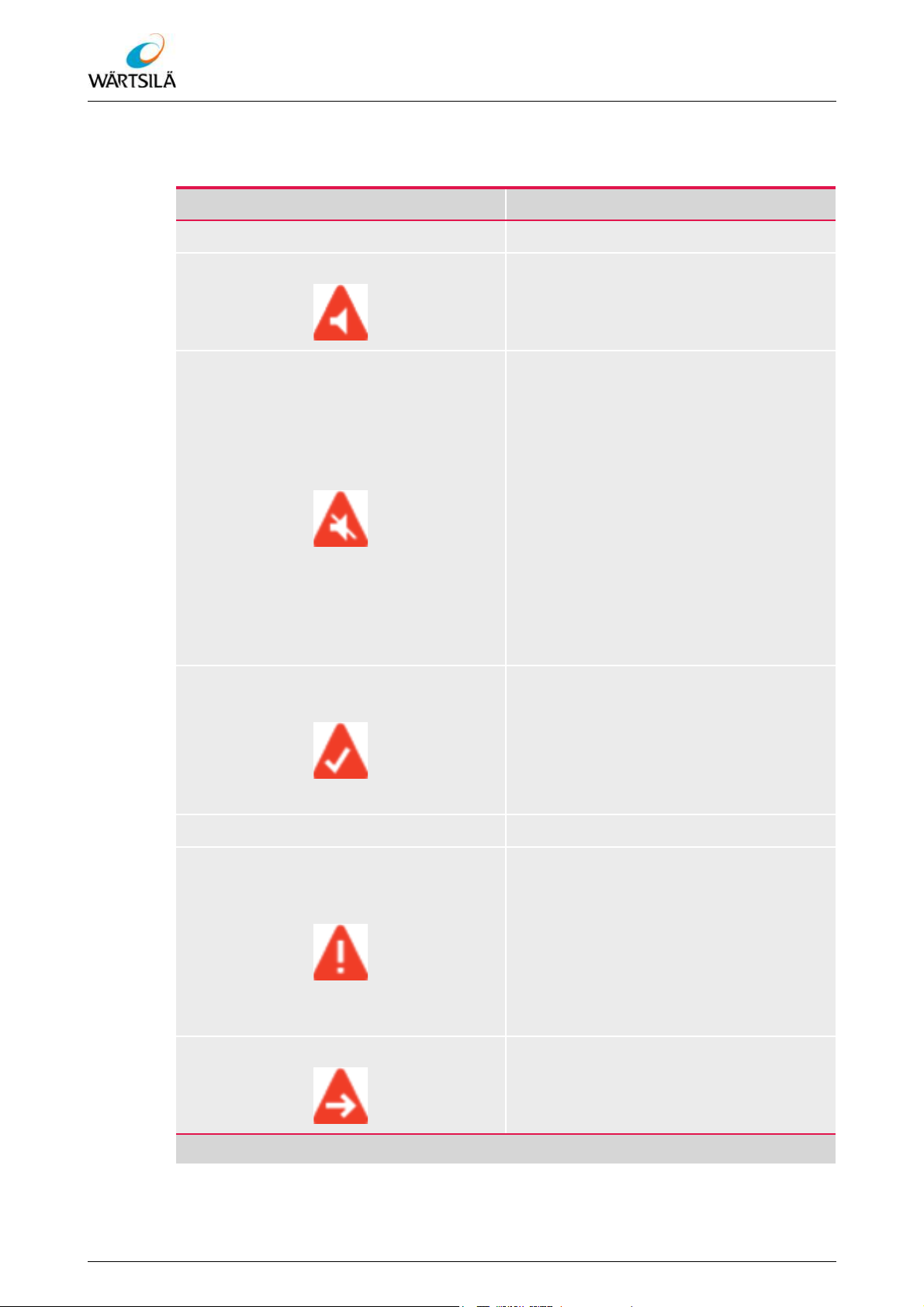
ELAC LAZ5200 – Operating Instructions
Operation
An overview of the possible alarm symbols and their meaning can be found in Table
6.8.
Alarm symbol Description
Unanswered alarms (flashing)
Unconfirmed alarm
• indicates that an alarm has been triggered, i.e. an alarm limit has been
overrun.
Muted alarm (silenced)
• indicates that an alarm has been triggered and the acoustic alarm signal
has been muted for 30 seconds.
• Possible only via the connected interfaces
Answered alarms (not flashing)
If the alarm continues to exist, the acoustic alarm signal sounds again after the
muting time.
This condition cannot be achieved by operation at the device; a corresponding
message (set ACN) has to be received via
an NMEA interface (serial or LWE).
Remedied, unconfirmed alarm
• indicates that an alarm limit had been
overrun, but that the measured value
is now within the alarm limits again.
• The display disappears when the confirmation key is pressed.
Confirmed alarm
• indicates that the alarm has been confirmed by pressing the confirmation
key or by a corresponding message
via an NMEA interface (serial or LWE).
• The display disappears when the
measured value is within the alarm
limits again.
Responsibility transferred
• Possible only via the connected interfaces
Tab. 6.8: Alarm Symbols
60 / 134 Wärtsilä ELAC Nautik GmbH TH 526148001 EN Rev. A 09/2018
Refer to protection notice ISO 16016
Page 63
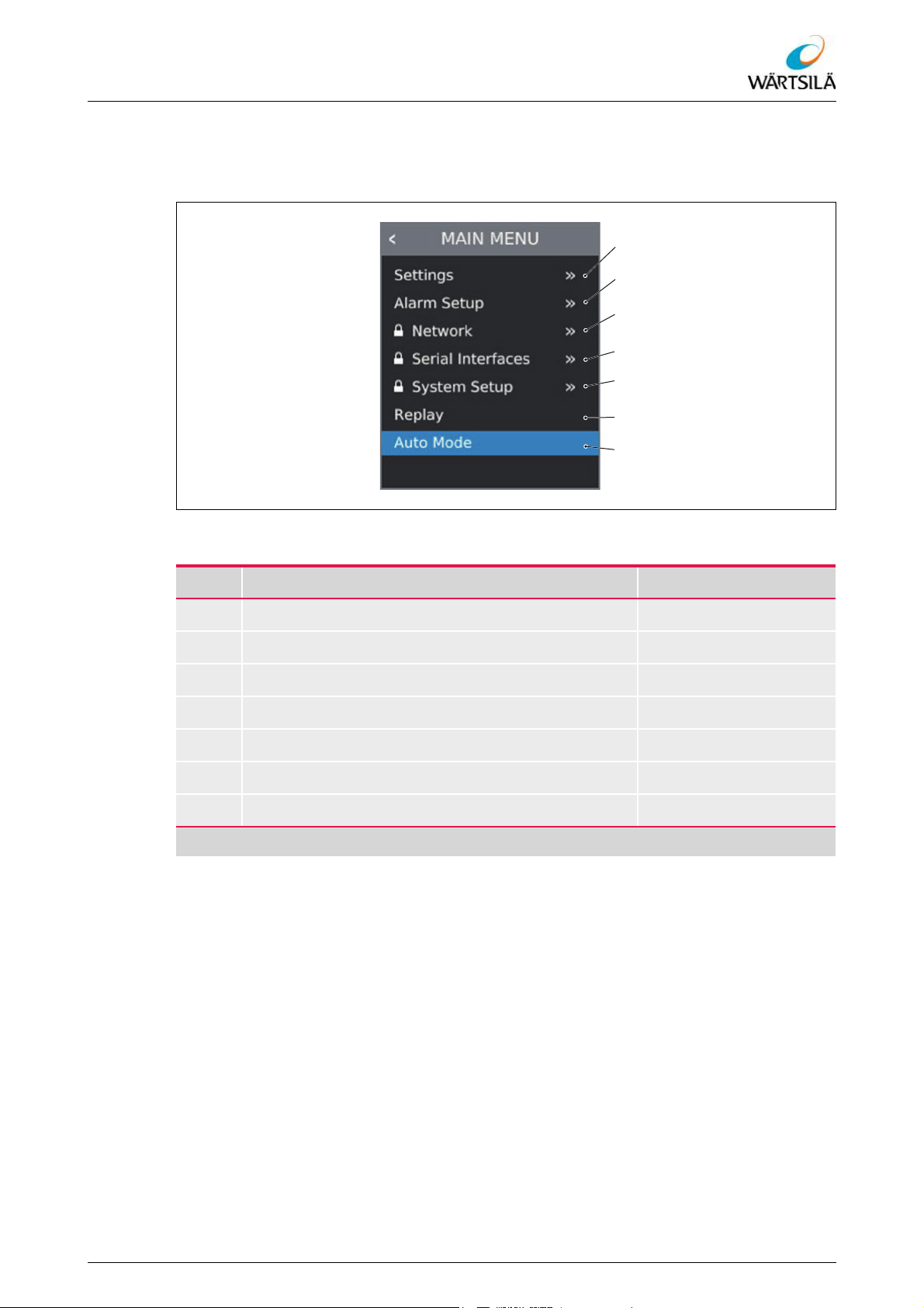
ELAC LAZ5200 – Operating Instructions
Operation
6.4 Description of the Menus
6.4.1 “MAIN MENU”
Fig. 6.21: “MAIN MENU”
Item Designation See section
Settings 6.4.2
Alarm setup 6.4.3
Network 6.4.4
Serial interfaces 6.4.5
System setup 6.4.7
Replay 6.4.8
Auto mode 6.4.9
Tab. 6.9: “MAIN MENU”
Refer to protection notice ISO 16016
TH 526148001 EN Rev. A 09/2018 Wärtsilä ELAC Nautik GmbH 61 / 134
Page 64
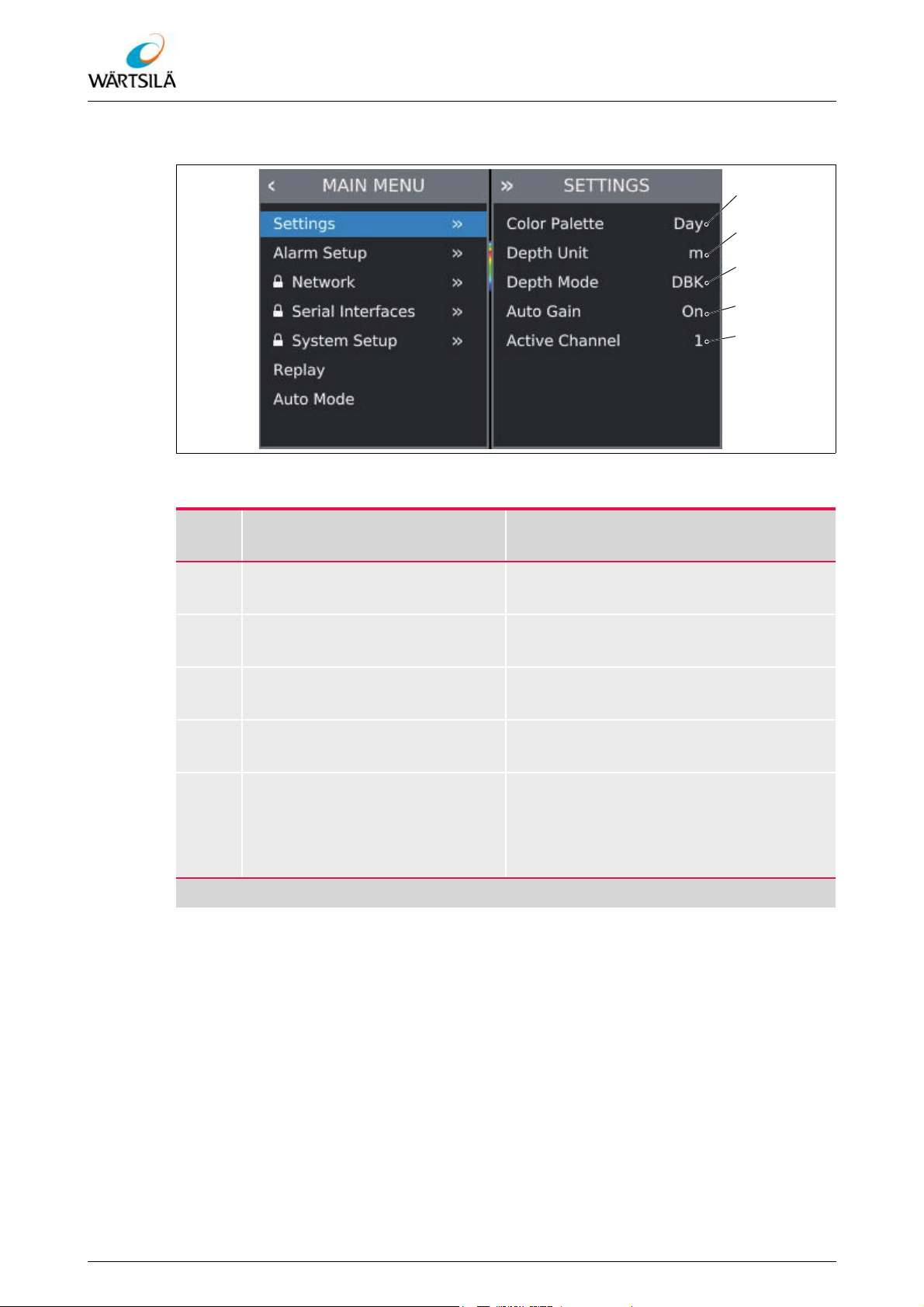
6.4.2 “SETTINGS” Menu
ELAC LAZ5200 – Operating Instructions
Operation
Fig. 6.22: “SETTINGS” Menu
Item Designation
Colour palette
Depth unit
Depth mode
Auto gain
Active channel
Description/
see section
Serves to select the display colour
6.5.7.3.
Serves to select the unit for the depth display 6.5.7.2.
Serves to select the depth mode
6.5.7.1.
Serves to activate and deactivate the "Auto Gain" function 6.5.5.2.
Serves to select the active channels
6.5.5.5.
The menu item is not displayed in systems with only one channel.
Tab. 6.10: “SETTINGS” Menu
62 / 134 Wärtsilä ELAC Nautik GmbH TH 526148001 EN Rev. A 09/2018
Refer to protection notice ISO 16016
Page 65

ELAC LAZ5200 – Operating Instructions
Operation
6.4.3 “ALARM SETUP” Menu
Fig. 6.23: “ALARM SETUP” Menu
Item Designation
Shallow alarm Shallow water alarm
Status
Depth
Deep alarm Deep water alarm
Status
Depth
Te st
Tab. 6.11: “ALARM SETUP” Menu
Description/
see section
Serves to activate and deactivate the
shallow water alarm 6.5.6.1.
Serves to set the upper alarm limit for the
water depth 6.5.6.2.
Serves to activate and deactivate the
deep water alarm 6.5.6.1.
Serves to set the lower alarm limit for the
water depth 6.5.6.2.
Serves to activate the test alarm
6.5.6.3.
Refer to protection notice ISO 16016
TH 526148001 EN Rev. A 09/2018 Wärtsilä ELAC Nautik GmbH 63 / 134
Page 66
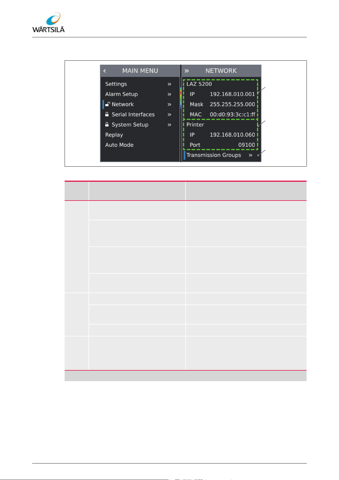
6.4.4 “NETWORK” Menu
ELAC LAZ5200 – Operating Instructions
Operation
Fig. 6.24: “NETWORK” Menu
Item Designation
LAZ 5200
IP
Mask
MAC
Printer Network settings of the printer
IP
Port Serves to set the printer port 6.5.11.3.
Transmission groups
Description/
see section
Network settings for the Navigation Echo
Sounder ELAC LAZ 5200
Serves to set the IP address of the Navigation Echo Sounder ELAC LAZ 5200
6.5.11.2.
Serves to set the network mask of the
Navigation Echo Sounder
ELAC LAZ 5200 6.5.11.2.
MAC address of the Navigation Echo
Sounder ELAC LAZ 5200 (invariable)
Serves to set the IP address of the printer
6.5.11.3.
Serves to select the transmission groups
that can be transmitted and received by
the Navigation Echo Sounder
ELAC LAZ 5200 6.5.11.4.
Tab. 6.12: “NETWORK” Menu
64 / 134 Wärtsilä ELAC Nautik GmbH TH 526148001 EN Rev. A 09/2018
Refer to protection notice ISO 16016
Page 67

ELAC LAZ5200 – Operating Instructions
Operation
6.4.5 “SERIAL INTERFACES” Menu
Fig. 6.25: “SERIAL INTERFACES” Menu
Item Designation
Description/
see section
RS422-1 Settings for the first serial port
RS422-2 Settings for the second serial port
RS422-3 Settings for the third serial port
RS422-4 Settings for the fourth serial port
Tab. 6.13: “SERIAL INTERFACES” Menu
Refer to protection notice ISO 16016
TH 526148001 EN Rev. A 09/2018 Wärtsilä ELAC Nautik GmbH 65 / 134
Page 68

6.4.6 Interface Configuration
The following figure shows the sub-menu for one of the four serial interfaces. The submenus for the other interfaces have the same structure.
ELAC LAZ5200 – Operating Instructions
Operation
Fig. 6.26: Interface Configuration
Item Designation
Baud rate
ALR
DPT
DBT
PELACSDS
ALC
ALF
HBT
Tab. 6.14: Interface Configuration
Further information on the NMEA data sets can be found in section 9.3 "Description
of the NMEA Data Sets".
Serves to set the Baud rate for the serial
interface
Serves to activate / deactivate transmission of the corresponding NMEA data set
6.5.11.5.
Description/
see section
66 / 134 Wärtsilä ELAC Nautik GmbH TH 526148001 EN Rev. A 09/2018
Refer to protection notice ISO 16016
Page 69

ELAC LAZ5200 – Operating Instructions
Operation
6.4.7 “SYSTEM SETUP” Menu
Fig. 6.27: “SYSTEM SETUP” Menu
Item Designation
Channel 1
Channel 2
Draft
Date and time
Alert ID
Factory settings
Description/
see section
Serves to configure the first receive channel.
6.5.11.1 "Configuration of a Channel"
Serves to configure the second receive
channel.
6.5.11.1 "Configuration of a Channel"
Serves to set the draft.
6.5.11.6 "Setting the Draft"
Serves to set date and time.
6.5.11.7 "Setting of the Date and Time"
Serves to set the alert ID of the device.
6.5.11.8 "Setting the Alarm ID"
Serves to reset all settings to the works
settings.
6.5.11.9 "Restoring the Factory
Settings"
Tab. 6.15: “SYSTEM SETUP” Menu
Refer to protection notice ISO 16016
TH 526148001 EN Rev. A 09/2018 Wärtsilä ELAC Nautik GmbH 67 / 134
Page 70

6.4.8 “Replay” Function
The "Replay" function serves to call up the history.
ELAC LAZ5200 – Operating Instructions
Operation
Fig. 6.28: Replay Menu
Further information on the “Replay” function can be found in section 6.5.8 "“History”
View".
6.4.9 “Auto Mode” Function
The "Auto Mode" function serves for automatic setting of the reception gain and depth
measuring range.
Fig. 6.29: “Auto Mode” Function
Further information on the “Auto Mode” function can be found in section 6.5.5.4
"Activation of the "Auto Mode" Function".
68 / 134 Wärtsilä ELAC Nautik GmbH TH 526148001 EN Rev. A 09/2018
Refer to protection notice ISO 16016
Page 71

ELAC LAZ5200 – Operating Instructions
OFF ON
Operation
6.5 Operation of the System
6.5.1 General
The Navigation Echo Sounder ELAC LAZ 5200 has a keyboard that is used to
• switch the device on and off;
• navigate within the menus and to select and activate menu items;
• control special functions (change depth measuring range, set marks, etc.).
Some functions are controlled via the menu, others can be controlled via special keys
on the keyboard (e.g. change depth measuring range).
Description of the keys, displays and their function 6.2.3.
Description of the navigation within the menus 6.5.4.
6.5.2 Switching ON the Navigation Echo Sounder ELAC LAZ 5200
NOTICE
Damage to the transducers possible!
The output of a transmission signal against air can result in damage to the connected
transducers.
The system may only be activated when the transducers are completely immersed
in water.
NOTICE
Damage to the transducers possible!
As soon as the device is switched on, it transmits signals continuously. Transmitting of
signals with the wrong transducer configuration can result in damage to the transducers
and the device.
Connect the transducers to the system only after configuration.
Carry out changes to the transducer configuration only with the transducers discon-
nected from the system.
Proceed as follows to switch on the Navigation Echo Sounder ELAC LAZ 5200:
1. Hold the [ON] key depressed briefly
(approx. 1 sec.).
– The unit is booted.
– The start screen is displayed after
5 to 10 seconds.
– The device starts to send transmis-
sion pulses.
Fig. 6.30: Switch On the Device
Refer to protection notice ISO 16016
TH 526148001 EN Rev. A 09/2018 Wärtsilä ELAC Nautik GmbH 69 / 134
After the booting of the device, the display area is blank. No data stored earlier are displayed when the device is rebooted.
Page 72

ELAC LAZ5200 – Operating Instructions
OFF ON
ENTER
ESCAPE
CURSOR
At each reboot, the device starts with the settings active before switching off. One exception is the display colour. The display colour is reset to the default setting "Day" at
each reboot of the device.
6.5.3 Switching OFF the Navigation Echo Sounder ELAC LAZ 5200
Proceed as follows to switch off the Navigation Echo Sounder ELAC LAZ 5200:
1. Hold the [OFF] key depressed for a
longer time (approx. 5 seconds).
– The unit shuts down.
Fig. 6.31: Switch Off Unit
Operation
If the [OFF] key is released before the device has shut down, the device continues with
normal operation.
The settings made are saved when the device is switched off. One exception is the display colour. The display colour is reset to the default setting "Day" at each reboot of the
device.
6.5.4 Operation of the Menu
The menu of the Navigation Echo Sounder ELAC LAZ 5200 is operated via the keyboard
on the device.
6.5.4.1 Opening the Menu
Proceed as follows to open the menu:
1. Press the [ENTER] key .
– The "MAIN MENU" opens in the
bottom left-hand corner of the display area.
70 / 134 Wärtsilä ELAC Nautik GmbH TH 526148001 EN Rev. A 09/2018
Fig. 6.32: Opening the Menu
Refer to protection notice ISO 16016
Page 73

ELAC LAZ5200 – Operating Instructions
ENTER
ESCAPE
CURSOR
Operation
6.5.4.2 Navigate in Menu
Proceed as follows to navigate in the menu:
1. Open the menu 6.5.4.1.
2. Navigate to the desired menu item using the [CURSOR] keys (up or
down).
– The currently selected menu item
is marked by a blue cursor .
– If the menu item has a sub-menu,
the sub-menu will be displayed to
the right of the currently selected
menu.
3. To switch to the sub-menu, press the
[ENTER] key .
– The cursor switches to a menu item
of the sub-menu.
Fig. 6.33: Navigation in the Menu
4. To return to the previous menu, press
the [ESCAPE] key .
Fig. 6.34: Cursor in the Menu
Menu items that have a sub-menu are indicated by the symbol ">>" on the right-hand
side.
Menu items marked with a lock symbol have to be unlocked before changes can be
made in the corresponding sub-menu ( 6.5.4.4 "Unlocking a Sub-menu"). Changes in
these menus may only be made by qualified personnel.
Pressing the [ESCAPE] key in the "MAIN MENU" closes the menu 6.5.4.5.
Refer to protection notice ISO 16016
TH 526148001 EN Rev. A 09/2018 Wärtsilä ELAC Nautik GmbH 71 / 134
Page 74
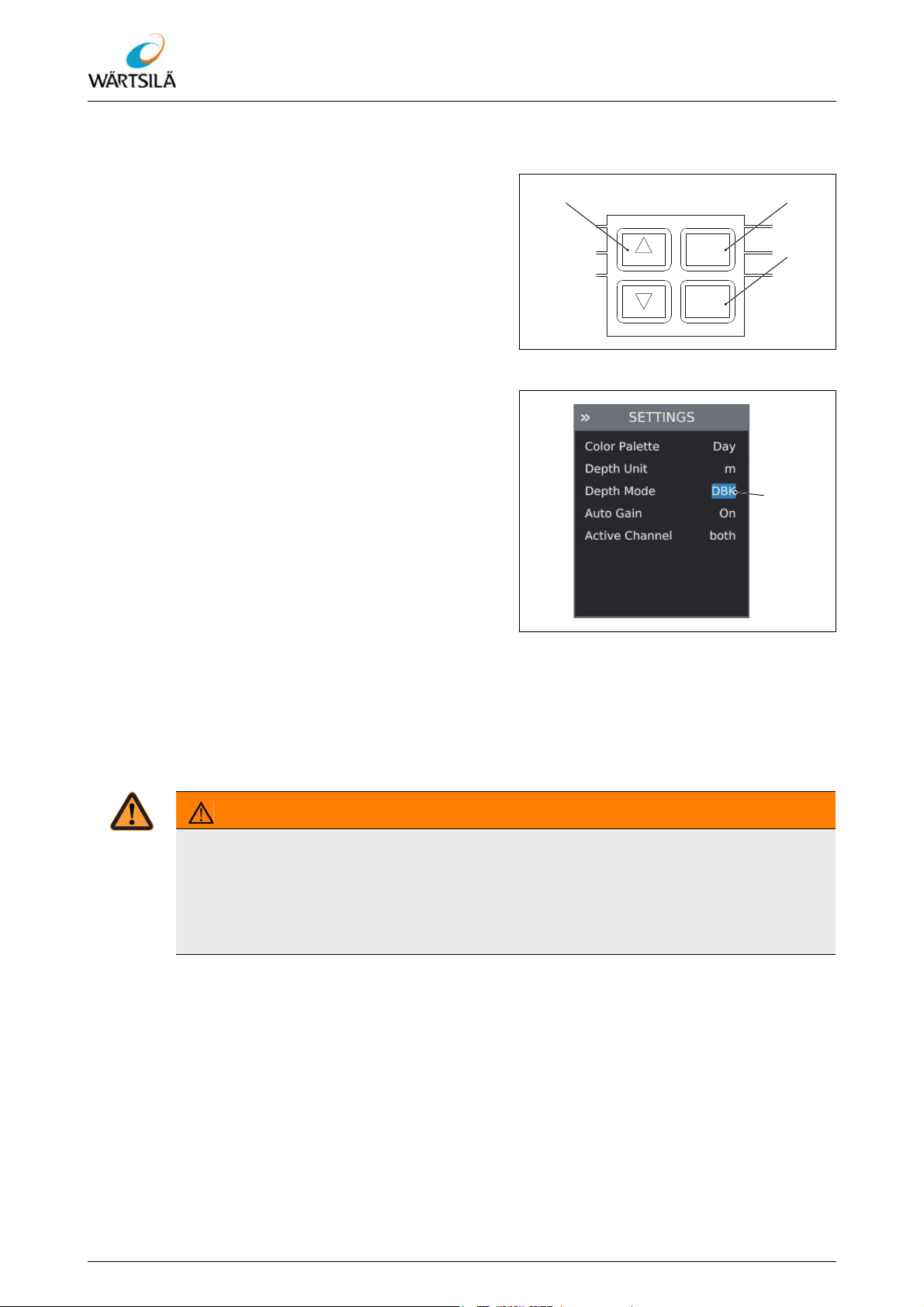
6.5.4.3 Changing a Parameter Value
ENTER
ESCAPE
CURSOR
Proceed as follows to change a parameter
value:
1. Open the menu 6.5.4.1.
2. Navigate to the corresponding menu
item 6.5.4.2.
3. Press the [ENTER] key .
– The cursor marks the current pa-
rameter value of the menu item.
4. Select the desired parameter value using the [CURSOR] keys (up or
down).
5. Press the [ENTER] key to confirm the
selection.
– The value is saved and the system
settings are changed accordingly.
ELAC LAZ5200 – Operating Instructions
Operation
Fig. 6.35: Change Parameter Value
6. Press the [ESCAPE] key to abort
the selection.
– The selected value is not saved
and the original value is retained.
6.5.4.4 Unlocking a Sub-menu
The parameters in some sub-menus may only be changed by qualified personnel. In order to be able to change the parameters in the sub-menu, the sub-menu has to be unlocked. Locked sub-menus are marked with a padlock in front of the corresponding menu
item in the "MAIN MENU".
WARNING!
Unauthorised changes can result in serious injury or even death.
Unauthorised modification of settings in a locked menu can endanger the safety of the
ship and result in serious injury or even death. In addition, the device and the transducers can be damaged if the device is operated with the wrong settings.
Changes to settings in locked menus may only be made by qualified personnel.
Fig. 6.36: Change Parameter Value
72 / 134 Wärtsilä ELAC Nautik GmbH TH 526148001 EN Rev. A 09/2018
Refer to protection notice ISO 16016
Page 75

ELAC LAZ5200 – Operating Instructions
ENTER
ESCAPE
CURSOR
Operation
Unlocking sub-menu
Proceed as follows to unlock a sub-menu:
1. Open the menu 6.5.4.1.
2. Navigate to the corresponding menu
item 6.5.4.2.
3. Press the [ENTER] key to confirm the
selection.
– The warning is displayed.
4. Select “Yes” by pressing the [CUR-
SOR] keys (up or down).
5. Press the [ENTER] key to confirm the
selection.
– The sub-menu is unlocked. The pa-
rameters can be changed.
– An open padlock is displayed in
front of the menu item in the "MAIN
MENU".
The sub-menu remains unlocked as long as the menu is open. If the menu is closed and
then opened again, the sub-menu has to be unlocked again.
6.5.4.5 Closing the Menu
Proceed as follows to close the menu:
1. Press the [ESCAPE] key .
– The menu is closed.
Fig. 6.37: Unlocking Sub-menu
Refer to protection notice ISO 16016
Fig. 6.38: Closing the Menu
The menu is only closed when the blue cursor is in the "MAIN MENU". If the cursor is in
a sub-menu, the [ESCAPE] key has to be pressed accordingly until the menu is closed.
TH 526148001 EN Rev. A 09/2018 Wärtsilä ELAC Nautik GmbH 73 / 134
Page 76

6.5.5 Settings for the Depth Measurement
RANGE
6.5.5.1 Setting the Depth Measuring Range
The depth measuring range can be set using the [RANGE] keys. The depth measuring
range should be set according to the depths to be expected. The best resolution is obtained when the difference between the displayed depth and the set depth measuring
range is as small as possible.
If the displayed depth is 30 m, for example, a better resolution will be obtained if the depth
measuring range is set to 50 m instead of 500 m.
If the depth measuring range is significantly larger than the actual depth, it is possible
that the Navigation Echo Sounder ELAC LAZ 5200 does not find the sea bed and a yellow question mark is displayed in the information field instead of the depth ( 6.3.2.1
"Information Field").
The depth measuring range can also be set automatically using the "Auto Mode" function ( 6.5.5.4 "Activation of the "Auto Mode" Function").
ELAC LAZ5200 – Operating Instructions
Operation
Setting the depth measuring range
Proceed as follows to set the depth measuring range:
1. To reduce the range, press the
[RANGE] key (up).
2. To increase the range, press the
[RANGE] key (down).
– The depth measuring range is set im-
mediately. No confirmation is neces-
Fig. 6.39: Setting the Depth Measuring Range
sary.
If the largest depth measuring range has been selected and the [RANGE] key (down)
is pressed again, the automatic depth measuring range function is activated and the device initially sets the depth measuring range to 200 m.
74 / 134 Wärtsilä ELAC Nautik GmbH TH 526148001 EN Rev. A 09/2018
Refer to protection notice ISO 16016
Page 77
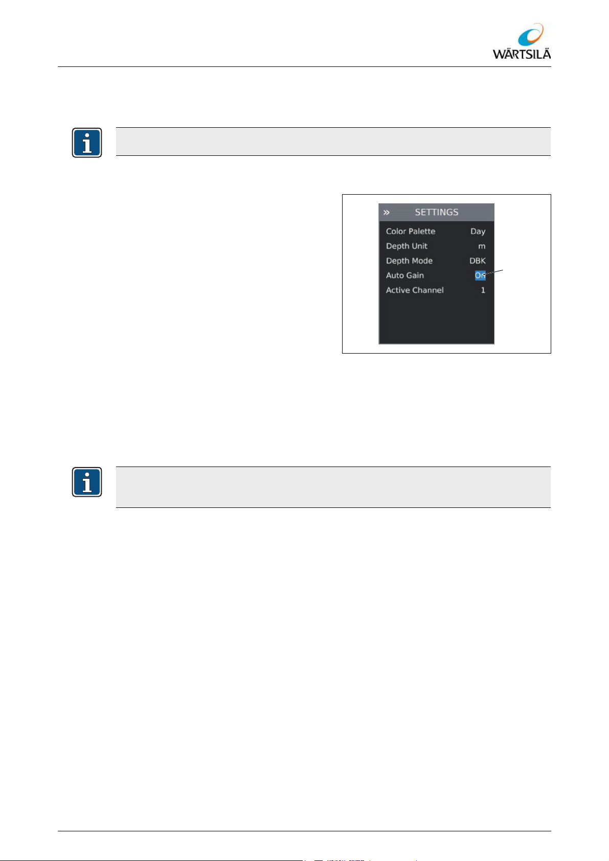
ELAC LAZ5200 – Operating Instructions
Operation
6.5.5.2 Activating and Deactivating the "Auto Gain" Function
The "Auto Gain" function serves for automatic setting of the reception gain.
The default setting is "On".
Activating and deactivating the "Auto Gain" Function
Proceed as follows to activate and deactivate the "Auto Gain" function:
1. Open the menu 6.5.4.
2. Select menu item MAIN MENU > SET-
TINGS > Auto Gain .
3. Press the [ENTER] key.
4. To activate the "Auto Gain" function,
select the “On” setting using the [CUR-
SOR] keys (up or down).
5. To deactivate the "Auto Gain" function,
select the “Off” setting using the [CUR-
Fig. 6.40: Activating and Deactivating the "Auto Gain"
function
SOR] keys (up or down).
6. Press the [ENTER] key to confirm the
selection.
– The "Auto Gain" function is activat-
ed or deactivated.
When the "Auto Gain" function is deactivated, the reception gain can be set manually.
A description of manual setting of the reception gain can be found in section 6.5.5.3.
Refer to protection notice ISO 16016
TH 526148001 EN Rev. A 09/2018 Wärtsilä ELAC Nautik GmbH 75 / 134
Page 78
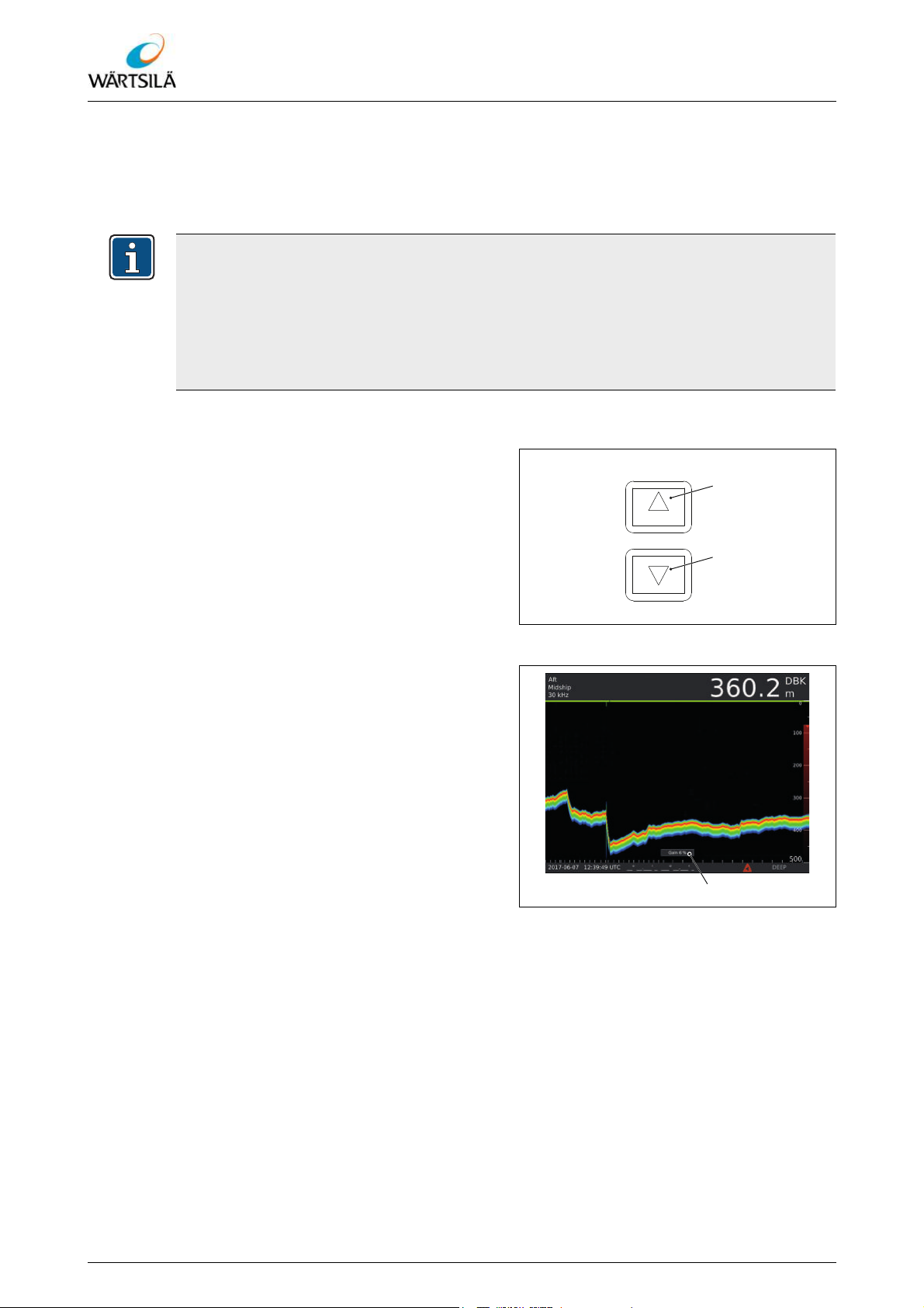
ELAC LAZ5200 – Operating Instructions
GAIN
6.5.5.3 Manual Setting of the Reception Gain ("GAIN")
The reception gain can be set manually using the [GAIN] keys. When the lowest setting
is selected, "Min Gain" appears in the display area. When the highest setting is selected,
"Max Gain" appears in the display area.
When the "Auto Gain" function is activated, the reception gain can still be set manually.
The "Auto Gain" function ensures only that the maximum gain level does not become
too large or too small. For this reason it is possible that the manually set reception gain
is immediately changed again automatically.
A description of activation and deactivation of the “Auto Gain” function can be found in
section 6.5.5.2 "Activating and Deactivating the "Auto Gain" Function".
Setting the reception gain
Proceed as follows to set the reception
gain:
Operation
1. To increase the reception gain, press
the [GAIN] key (up).
2. To decrease the reception gain, press
the [GAIN] key (down).
– The reception gain is set immediately.
No confirmation is necessary. The set
reception gain is shown briefly in the
display area.
Fig. 6.41: Setting the Reception Gain
Fig. 6.42: Display in the Display Area
76 / 134 Wärtsilä ELAC Nautik GmbH TH 526148001 EN Rev. A 09/2018
Refer to protection notice ISO 16016
Page 79
ELAC LAZ5200 – Operating Instructions
Operation
6.5.5.4 Activation of the "Auto Mode" Function
The "Auto Mode" function is used to automatically set the reception gain and the depth
measuring range. When the function is activated, the reception gain and the depth measuring range are set once to values that provide the best possible display of the echo in
the display area. The reception gain and the depth measuring range can then be
changed again manually.
Automatic setting of the depth measuring range functions only in a range between 50
and 200 m. With greater depths ( 300), the depth cannot be measured automatically.
In this case, a larger depth measuring range can be set manually 6.5.5.1.
If the depth measuring range has been set using the "Auto Mode" function, the letter “A”
is displayed alongside the maximum value of the depth measuring range.
Activating the "Auto Mode” function
Proceed as follows to activate the "Auto
Mode" function:
1. Open the menu 6.5.4.1.
2. Select menu item MAIN MENU > Auto
Mode .
3. Press the [ENTER] key to confirm the
selection.
– The reception gain and depth mea-
suring range area set.
Fig. 6.43: Activating the "Auto Mode” Function
In 2-channel mode, the larger depth measuring range is set automatically if the two
channels measure different depths.
Refer to protection notice ISO 16016
TH 526148001 EN Rev. A 09/2018 Wärtsilä ELAC Nautik GmbH 77 / 134
Page 80

6.5.5.5 Selecting the Active Channels
Depending on the variant, the Navigation Echo Sounder ELAC LAZ 5200 has one or two
channels. On systems with two channels, the channels can be activated or deactivated
independently of one another.
The number of active channels influences the display on the screen of the Navigation
Echo Sounder ELAC LAZ 5200. The available channels can be selected either individually or together. If only one receive channel is active, the whole width is used to display
the information on this receive channel. If both channels are active at the same time, the
information field and display area are split and the information on the two channels is displayed alongside one another. Receive channel 1 is displayed on the left-hand side. Receive channel 2 is displayed on the right-hand side.
The following settings are available:
Designation Description
1 Channel 1 is active.
ELAC LAZ5200 – Operating Instructions
Operation
2 Channel 2 is active.
both Channel 1 and channel 2 are active.
Tab. 6.16: Number of Active Channels
The default setting is "1".
Selecting active channels
Proceed as follows to select the number of
active channels:
1. Open the menu 6.5.4.
2. Select menu item MAIN MENU > SET-
TINGS > Active Channel .
3. Press the [ENTER] key.
4. Select the desired setting with the
[CURSOR] keys (up or down).
5. Press the [ENTER] key to confirm the
selection.
– The display of the channels on the
screen is adapted accordingly.
Fig. 6.44: Selecting Active Channels
78 / 134 Wärtsilä ELAC Nautik GmbH TH 526148001 EN Rev. A 09/2018
Refer to protection notice ISO 16016
Page 81
ELAC LAZ5200 – Operating Instructions
Operation
6.5.6 Settings for the Depth Alarm
6.5.6.1 Activating and Deactivating the Depth Alarm
The depth alarm can be activated and deactivated for shallow water (Shallow alarm) and
for deep water (Deep alarm). If one or both alarms are activated, the corresponding alarm
limits are shown in the display area ( 6.3.2.2.2 "Representation of Alarm Limits").
A description of setting the alarm limits can be found in section 6.5.6.2.
The default setting for both alarms is "Off".
Activating or deactivating the alarm function
Proceed as follows to activate or deactivate
the alarm function:
1. Open the menu 6.5.4.
2. Select menu item MAIN MENU >
ALARM SETUP > Status of the re-
spective alarm.
3. Press the [ENTER] key.
4. To activate the alarm, select the “On”
setting using the [CURSOR] keys (up
or down).
5. To deactivate the alarm, select the “Off”
setting using the [CURSOR] keys (up
or down).
6. Press the [ENTER] key to confirm the
selection.
– The alarm is activated or deactivat-
ed.
Fig. 6.45: Activating or Deactivating the Alarm
Refer to protection notice ISO 16016
TH 526148001 EN Rev. A 09/2018 Wärtsilä ELAC Nautik GmbH 79 / 134
Page 82

6.5.6.2 Setting the Alarm Limits
The alarm limits for the shallow water alarm and the deep water alarm can be set in a
range from 0 to 9999 m. The alarm limits of activated alarms are shown on the scale of
the depth measuring range in the display area ( 6.3.2.2.2 "Representation of Alarm
Limits").
The alarm limits are always set in metres, irrespective of the selected unit for the depth
display ( 6.5.7.2 "Selection of the Unit for the Depth Display").
The set value is always referred to the distance from the water surface, irrespective of
the selected reference point ( 6.5.7.1 "Selection of the Reference Point").
The default setting for the shallow water alarm limit is "0 m". The default setting for the
deep water alarm limit is "1000 m".
Setting the alarm limit
ELAC LAZ5200 – Operating Instructions
Operation
Proceed as follows to set the alarm limit:
1. Open the menu 6.5.4.
2. Select menu item MAIN MENU >
ALARM SETUP > Depth of the re-
spective alarm.
3. Press the [ENTER] key.
4. Set the figures for the alarm limit using
the [CURSOR] keys (up and down)
and confirm in each by pressing the
[ENTER] key.
– After setting the last digit and
pressing the [ENTER] key, the set
value for the alarm limit is saved.
Fig. 6.46: Setting the Alarm Limit
80 / 134 Wärtsilä ELAC Nautik GmbH TH 526148001 EN Rev. A 09/2018
Refer to protection notice ISO 16016
Page 83

ELAC LAZ5200 – Operating Instructions
Operation
6.5.6.3 Activation of the Test Alarm
The test alarm simulates a shallow water alarm for a duration of one second. When the
test alarm is triggered, an acoustic alarm sounds and the alarm is displayed in the status
bar of the Navigation Echo Sounder ELAC LAZ 5200 and on all the interfaces (NMEA
and relay). If the real alarm state changes during the test, the test alarm is automatically
aborted.
Activating the test alarm
Proceed as follows to activate the test
alarm:
1. Open the menu 6.5.4.
2. Select menu item MAIN MENU >
ALARM SETUP > Test of the re-
spective alarm.
3. Press the [ENTER] key.
– The warning "TEST ALARM" is dis-
played.
4. Select “Yes” using the [CURSOR] keys
(up or down).
5. Press the [ENTER] key to confirm the
selection.
– The shallow water alarm is trig-
gered for a duration of one second.
Fig. 6.47: Activating the Test Alarm
Fig. 6.48: Activating the Test Alarm
Refer to protection notice ISO 16016
TH 526148001 EN Rev. A 09/2018 Wärtsilä ELAC Nautik GmbH 81 / 134
Page 84

6.5.7 Settings for the Display
6.5.7.1 Selection of the Reference Point
The following settings are available:
Designation Description
ELAC LAZ5200 – Operating Instructions
Operation
"Depth Below Keel"
DBK
DBT
DBS
Tab. 6.17: Units for the Depth Display
The default setting is "DBK".
Selecting the reference point
Proceed as follows to select the reference
point:
Display of the water depth under the keel
(distance between the keel and the sea
bed)
"Depth Below Transducer"
Display of the water depth under the
transducer (distance between the transducer and the sea bed)
"Depth Below Surface"
Display of the water depth under the water surface (distance between the water
surface and the sea bed)
1. Open the menu 6.5.4.
2. Select menu item MAIN MENU > SET-
TINGS > Depth Mode .
3. Press the [ENTER] key.
4. Select the desired setting with the
[CURSOR] keys (up or down).
5. Press the [ENTER] key to confirm the
selection.
– The reference point is set.
Fig. 6.49: Selecting the Reference Point
Refer to protection notice ISO 16016
82 / 134 Wärtsilä ELAC Nautik GmbH TH 526148001 EN Rev. A 09/2018
Page 85

ELAC LAZ5200 – Operating Instructions
Operation
6.5.7.2 Selection of the Unit for the Depth Display
The following settings are available:
Designation Description
m Metres
ft Feet
fm Fathoms
Tab. 6.18: Units for the Depth Display
The default setting is "m" (metres).
Selecting the unit for the depth display
Proceed as follows to select the unit for the
depth display:
1. Open the menu 6.5.4.
2. Select menu item MAIN MENU > SET-
TINGS > Depth Unit .
3. Press the [ENTER] key.
4. Select the desired setting with the
[CURSOR] keys (up or down).
5. Press the [ENTER] key to confirm the
selection.
– The unit for the depth display is set.
Fig. 6.50: Selecting the Unit for the Depth Display
Refer to protection notice ISO 16016
TH 526148001 EN Rev. A 09/2018 Wärtsilä ELAC Nautik GmbH 83 / 134
Page 86

6.5.7.3 Selection of the Display Colour
The following settings are available:
Designation Description
Day ---
Dusk ---
Night ---
B.Off Backlight Off
The default setting is "Day".
Selecting the display colour
ELAC LAZ5200 – Operating Instructions
Operation
Tab. 6.19: Display Colours
Proceed as follows to select the display colour:
1. Open the menu 6.5.4.
2. Select menu item MAIN MENU > SET-
TINGS > Color Palette .
3. Press the [ENTER] key.
4. Select the desired setting with the
[CURSOR] keys (up or down).
5. Press the [ENTER] key to confirm the
selection.
– The display colour of the screen is
being set. This can take a few seconds.
Fig. 6.51: Selecting the Display Colour
84 / 134 Wärtsilä ELAC Nautik GmbH TH 526148001 EN Rev. A 09/2018
Refer to protection notice ISO 16016
Page 87

ELAC LAZ5200 – Operating Instructions
DIM
Operation
6.5.7.4 Setting of the Background Lighting
The background lighting of the display and keyboard can be set using the [DIM] keys.
The brightness can be adjusted in ten levels. The default brightness after power-up is
50 %.
After adjusting the brightness, the default / standard brightness can be reset by pressing
the [DIM] key (down) a maximum of ten times and pressing the [DIM] key (up) five
times.
Set background lighting
Proceed as follows to set the background
lighting:
1. To increase the brightness, press the
[DIM] key (up).
2. To decrease the brightness, press the
[DIM] key (down).
– The background lighting is set immedi-
ately. No confirmation is necessary.
Fig. 6.52: Set Background Lighting
Refer to protection notice ISO 16016
TH 526148001 EN Rev. A 09/2018 Wärtsilä ELAC Nautik GmbH 85 / 134
Page 88

6.5.8 “History” View
The history allows the saved depth data to be displayed and printed out. Up to 168 hours
of data can be saved.
ELAC LAZ5200 – Operating Instructions
Operation
Fig. 6.53: “History” View
When the history is open, the display “REPLAY” appears in the status bar. The recorded echogram with any set marking lines is shown in the display area. The information
in the information field as well as the date, time and position data refer to the first data set
on the right-hand side of the display area. If the cursor is displayed, the information refers
to the data set marked by the cursor.
The intervals on the time axis in the history are always 5 seconds per pixel column, irrespective of the depth measuring range set at the time.
If a depth alarm is triggered while the history is open, the history is automatically closed.
A description of printing out the history can be found in section 6.5.9 "Print
("PRINT")".
86 / 134 Wärtsilä ELAC Nautik GmbH TH 526148001 EN Rev. A 09/2018
Refer to protection notice ISO 16016
Page 89

ELAC LAZ5200 – Operating Instructions
CURSOR
Operation
6.5.8.1 Opening the History
The history can only be opened when no depth alarm is active. In the event of an active
depth alarm, the history is automatically closed.
Proceed as follows to open the history:
1. Open the menu 6.5.4.1.
2. Navigate to menu item MAIN MENU >
Replay .
3. Press the [ENTER] key to confirm the
selection.
– The history is opened. The mes-
sage "REPLAY" is displayed in
the status bar.
When the history is opened, the stored data needs a few seconds to load. During this
loading time, the display area remains black. The message "Loading replay data…" is
displayed in the lower part of the display area.
6.5.8.2 Scrolling in the History
Proceed as follows to scroll in the history:
1. To display older data, press the [CURSOR] key (down).
– The screen capture is scrolled to
the right.
2. To display newer data, press the [CUR-
SOR] key (up).
– The screen capture is scrolled to
the left.
Fig. 6.54: Opening the History
Fig. 6.55: “REPLAY” Message
Fig. 6.56: Scrolling in the History
The [RANGE] keys allow the depth measuring range in the history to be modified.
Refer to protection notice ISO 16016
TH 526148001 EN Rev. A 09/2018 Wärtsilä ELAC Nautik GmbH 87 / 134
Page 90
6.5.8.3 Controlling the Cursor in the History
ENTER
ESCAPE
CURSOR
Pressing the [MARKER] key in the "History" view displays a cursor in the form of a vertical white line. The cursor can be moved to the left and right in the display area using the
[CURSOR] keys (up or down).
When the cursor is displayed, the information in the information fields as well as the date,
time and position data refer to the current position of the cursor.
6.5.8.4 Closing the History
Proceed as follows to close the history:
1. Press the [ESCAPE] key .
– The history is closed.
ELAC LAZ5200 – Operating Instructions
Operation
6.5.9 Print ("PRINT")
Printing always prints the current screen display (current sounding plot or history).
Print
Precondition:
A corresponding network printer has been configured.
Proceed as follows to print:
1. Press the [PRINT] key .
– The current screen display is print-
ed.
Fig. 6.57: Closing the History
PRINT
Fig. 6.58: Print
88 / 134 Wärtsilä ELAC Nautik GmbH TH 526148001 EN Rev. A 09/2018
Refer to protection notice ISO 16016
Page 91
ELAC LAZ5200 – Operating Instructions
Operation
6.5.10 Exporting of Recorded Data
The data recorded by the Navigation Echo Sounder ELAC LAZ 5200 can be stored on a
USB stick. In order for data to be stored on the USB stick, the USB stick has to satisfy
certain preconditions.
Designation Description
File system FAT32
Free memory space min. 4 GB
Miscellaneous
Tab. 6.20: Preconditions for the USB Stick
• The USB stick must be empty.
• The USB stick must be max. 4.5 cm in
length. Longer USB sticks will not fit
behind the service panel of the Navigation Echo Sounder
ELAC LAZ 5200.
Exporting data
Precondition:
A suitable USB stick is available ( Tab. 6.20: "Preconditions for the USB Stick").
Proceed as follows to export data:
1. Switch off the device 6.5.3.
2. Open the service panel on the rear of
the device:
3. Insert the USB stick into the USB port
behind the service panel.
4. Close the service panel.
5. Switch on the device 6.5.2.
Fig. 6.59: Exporting Data
– The warning is displayed.
– When the data have been copied,
the device boots in the normal
manner.
6. Switch off the device 6.5.3.
7. Open the service panel on the rear of
the device:
8. Remove the USB stick from the USB
port.
9. Close the service panel.
Refer to protection notice ISO 16016
The data are stored on the USB stick in the directory "records".
The data are stored in CSV format. A more detailed description can be obtained from
the manufacturer.
TH 526148001 EN Rev. A 09/2018 Wärtsilä ELAC Nautik GmbH 89 / 134
Page 92

6.5.11 Configuration
6.5.11.1 Configuration of a Channel
Depending on the variant, the Navigation Echo Sounder ELAC LAZ 5200 has one or two
channels. The parameters for the channels are set during commissioning of the Naviga-
tion Echo Sounder ELAC LAZ 5200 and may only be changed if modifications are made
to the system (e.g. changing of the transducer model).
The following parameters can be configured:
Designation Description
ELAC LAZ5200 – Operating Instructions
Operation
Installation position of the transducer in
longitudinal direction
Along
The following settings are available:
•Aft
•Center
•Bow
Installation position of the transducer in
transverse direction
The following settings are available:
Across
• Starboard
• Midship
•Port
Model Transducer model or "none"
Trim
Distance between transducer and keel in
metres
Blocking depth in metres
The blocking depth defines the distance
under the transducer at which the depth
Blocking depth
measurement is to be started. This prevents, for example, an echo reflected by
parts of the ship in the vicinity of the transducer leading to wrong depth measurement values.
Tab. 6.21: Parameters of the Channels
WARNING!
Unauthorised changes can result in serious injury or even death.
Unauthorised modification of the configuration parameters can endanger the safety of
the ship and result in very serious injury or even death.
Changes to the configuration parameters may only be made by qualified personnel.
90 / 134 Wärtsilä ELAC Nautik GmbH TH 526148001 EN Rev. A 09/2018
Refer to protection notice ISO 16016
Page 93

ELAC LAZ5200 – Operating Instructions
Operation
Configuring the channel
Precondition:
The "SYSTEM SETUP" menu is unlocked 6.5.4.4.
Proceed as follows to configure a channel:
1. Navigate to the menu MAIN MENU >
SYSTEM SETUP and select the de-
sired channel or .
2. Press the [ENTER] key.
3. Select menu item “Along” and press
the [ENTER] key.
4. Select the desired setting with the
[CURSOR] keys (up or down) and confirm with the [ENTER] key.
5. Select menu item “Across” and
press the [ENTER] key.
6. Select the desired setting with the
[CURSOR] keys (up or down) and confirm with the [ENTER] key.
7. Select menu item “Model” and press
the [ENTER] key.
8. Select the desired setting with the
[CURSOR] keys (up or down) and confirm with the [ENTER] key.
Fig. 6.60: Configuring the Channel
Refer to protection notice ISO 16016
A transducer must be configured for the depth detection to work, i. e. "none" must not
be set under "Model".
9. Select menu item “Trim” and press
the [ENTER] key.
10. Set the desired value using the [CUR-
SOR] keys (up or down) and confirm
with the [ENTER] key.
11. Select menu item “Blocking depth”
and press the [ENTER] key.
12. Set the desired value using the [CUR-
SOR] keys (up or down) and confirm
with the [ENTER] key.
Fig. 6.61: Configuring the Channel
TH 526148001 EN Rev. A 09/2018 Wärtsilä ELAC Nautik GmbH 91 / 134
Page 94

ELAC LAZ5200 – Operating Instructions
6.5.11.2 Configuring the Network Settings for the Navigation Echo Sounder
ELAC LAZ 5200
Changes to the network settings are only active after a reboot of the device.
The MAC address of the device cannot be changed.
Setting the MAC address of the Navigation Echo Sounder ELAC LAZ 5200
Precondition:
The "NETWORK" menu is unlocked 6.5.4.4.
Proceed as follows to set the IP address:
1. Select menu item MAIN MENU > NETWORK > IP.
2. Press the [ENTER] key.
Operation
3. Set the digits of the IP address in turn
using the [CURSOR] keys (up or down)
and confirm each with the [ENTER]
key.
– After setting the last digit and
pressing the [ENTER] key, the set
IP address is saved.
Fig. 6.62: Setting the IP Address
4. Reboot the device 6.5.3.
Only IP addresses in the range 172.16.0.1 to 172.31.255.254 with the network mask
255.255.0.0 are conform to IEC 61162-450.
If the IP address of the Navigation Echo Sounder ELAC LAZ 5200 is changed, the
source ID for the TAG blocks also changes ( 9.2.3 "Calculation of the Source ID for
TAG Blocks").
92 / 134 Wärtsilä ELAC Nautik GmbH TH 526148001 EN Rev. A 09/2018
Refer to protection notice ISO 16016
Page 95

ELAC LAZ5200 – Operating Instructions
Operation
Setting the network mask of the Navigation Echo Sounder ELAC LAZ 5200
Precondition:
The "NETWORK" menu is unlocked 6.5.4.4.
Proceed as follows to set the network
mask:
1. Select menu item MAIN MENU > NETWORK > Mask.
2. Press the [ENTER] key.
3. Set the digits of the network mask in
turn using the [CURSOR] keys (up or
down) and confirm each with the [EN-
TER] key.
– After setting the last digit and
pressing the [ENTER] key, the set
network mask is saved.
Fig. 6.63: Setting the Network Mask
4. Reboot the device 6.5.3.
6.5.11.3 Configuring the Network Settings of the Printer
Changes to the network settings are only active after a reboot of the device.
Setting the IP address of the printer
Precondition:
The "NETWORK" menu is unlocked 6.5.4.4.
Proceed as follows to set the IP address:
1. Select menu item MAIN MENU > NETWORK > IP.
2. Press the [ENTER] key.
3. Set the digits of the IP address in turn
using the [CURSOR] keys (up or down)
and confirm each with the [ENTER]
key.
– After setting the last digit and
pressing the [ENTER] key, the set
IP address is saved.
Fig. 6.64: Setting the IP Address
4. Reboot the device 6.5.3.
Refer to protection notice ISO 16016
TH 526148001 EN Rev. A 09/2018 Wärtsilä ELAC Nautik GmbH 93 / 134
Page 96

ELAC LAZ5200 – Operating Instructions
Setting the printer port
Precondition:
The "NETWORK" menu is unlocked 6.5.4.4.
Proceed as follows to set the printer port:
1. Select menu item MAIN MENU > NETWORK > Port .
2. Press the [ENTER] key.
3. Set the digits of the printer port in turn
using the [CURSOR] keys (up or down)
and confirm each with the [ENTER]
key.
– After setting the last digit and
pressing the [ENTER] key, the set
printer port is saved.
Operation
Fig. 6.65: Setting the Printer Port
4. Reboot the device 6.5.3.
6.5.11.4 Configuring the Ethernet Interface
The Navigation Echo Sounder ELAC LAZ 5200 has an Ethernet interface via which
NMEA data sets can be transmitted and received. The following transmission groups are
available for the transmission:
•MISC
•TGTD
•SATD
•NAVD
•VDRD
• RCOM
•TIME
•PROP
• USR1 to USR8
USR1 to USR8 are user-defined transmission groups.
Further information on the NMEA data sets can be found in section 9.3 "Description
of the NMEA Data Sets".
Only one transmission group can be selected for the transmission of data sets. By contrast with the serial interfaces, there is no filter as to which data sets are to be published.
The available transmission groups can be activated and deactivated individually for receiving data sets.
No destination ID is entered in TAG blocks.
Changes to the network settings are only active after a reboot of the device.
94 / 134 Wärtsilä ELAC Nautik GmbH TH 526148001 EN Rev. A 09/2018
Refer to protection notice ISO 16016
Page 97

ELAC LAZ5200 – Operating Instructions
Operation
6.5.11.4.1 Selection of the Transmission Group for the Output
The default setting is "NAVD".
Select the transmission group for the output
Precondition:
The "NETWORK" menu is unlocked 6.5.4.4.
Proceed as follows to select the transmission group:
1. Select menu item MAIN MENU > NETWORK > TX GROUPS > Output .
2. Press the [ENTER] key.
3. Select the desired setting with the
[CURSOR] keys (up or down).
4. Press the [ENTER] key to confirm the
selection.
5. Reboot the device. 6.5.3
Fig. 6.66: Selecting Transmission Group (Output)
6.5.11.4.2 Selection of the Standard Transmission Groups for the Input
The default setting for the transmission groups NAVD and TIME is "On". The default setting for all other transmission groups is "Off".
Select the transmission groups for the input
Precondition:
The "NETWORK" menu is unlocked 6.5.4.4.
Proceed as follows to select the transmission groups:
1. Navigate to the menu MAIN MENU >
NETWORK > TX GROUPS > STANDARD GROUPS.
2. Select the desired menu item and
press the [ENTER] key.
3. Select the setting “On” with the [CURSOR] keys (up or down).
4. Press the [ENTER] key to confirm the
selection.
Fig. 6.67: Selecting Transmission Group (Input)
5. Repeat steps 2 to 4 to select further
Refer to protection notice ISO 16016
transmission groups.
6. Reboot the device 6.5.3.
TH 526148001 EN Rev. A 09/2018 Wärtsilä ELAC Nautik GmbH 95 / 134
Page 98

ELAC LAZ5200 – Operating Instructions
6.5.11.4.3 Selection of the User-Defined Transmission Groups for the Input
The default setting for all user-defined Transmission Groups is "Off".
Precondition:
The "NETWORK" menu is unlocked 6.36.
Proceed as follows to select the user-defined transmission groups:
1. Navigate to the menu MAIN MENU >
NETWORK > TX GROUPS > USER
GROUPS.
2. Select the desired menu item and
press the [ENTER] key.
3. Select the setting “On” with the [CUR-
SOR] keys (up or down).
Operation
4. Press the [ENTER] key to confirm the
selection.
5. Repeat steps 2 to 4 to select further
user-defined transmission groups.
6. Reboot the device 6.5.3.
Fig. 6.68: Selecting User Groups
96 / 134 Wärtsilä ELAC Nautik GmbH TH 526148001 EN Rev. A 09/2018
Refer to protection notice ISO 16016
Page 99

ELAC LAZ5200 – Operating Instructions
Operation
6.5.11.5 Configuration of the Serial Interfaces
The Navigation Echo Sounder ELAC LAZ 5200 has four serial interfaces via which alarm
information, depth information and information on the device status can be transmitted.
Various NMEA data sets are available for transmission of the information.
All serial interfaces function in the same way.
The pin assignment of the interfaces on the Navigation Echo Sounder ELAC LAZ 5200
can be found in the connection plan ( 9.1 "Applicable Documents").
The data sets that can be transmitted via the interface can be defined individually for each
interface in the "SERIAL INTERFACES" menu.
The following NMEA data sets are available:
Designation Description
ALC
ALF
ALR
DPT
DBT
HBT
PELACSDS
Standard NMEA data set for ensuring a
secure and consistent data distribution.
Standard NMEA data set for signalling the
alarm status.
Standard NMEA data set for signalling the
alarm status.
Standard NMEA data set, contains the
water depth in metres.
Standard NMEA data set, contains the
depth under the transducer in fathoms,
metres and feet.
Standard NMEA data set, contains information on the device status.
Proprietary NMEA data set, contains information on the set parameters and the
installation position of the transducer in
addition to the water depth.
Tab. 6.22: NMEA Data Sets
The BAM-compliant sets ALC and ALF should be used instead of ALR. ALR is contained only for reasons of compatibility with older environments.
Further information on the NMEA data sets can be found in section 9.3 "Description
of the NMEA Data Sets".
Refer to protection notice ISO 16016
TH 526148001 EN Rev. A 09/2018 Wärtsilä ELAC Nautik GmbH 97 / 134
The default setting for the Baud rate for all serial interfaces is "4800".
Page 100
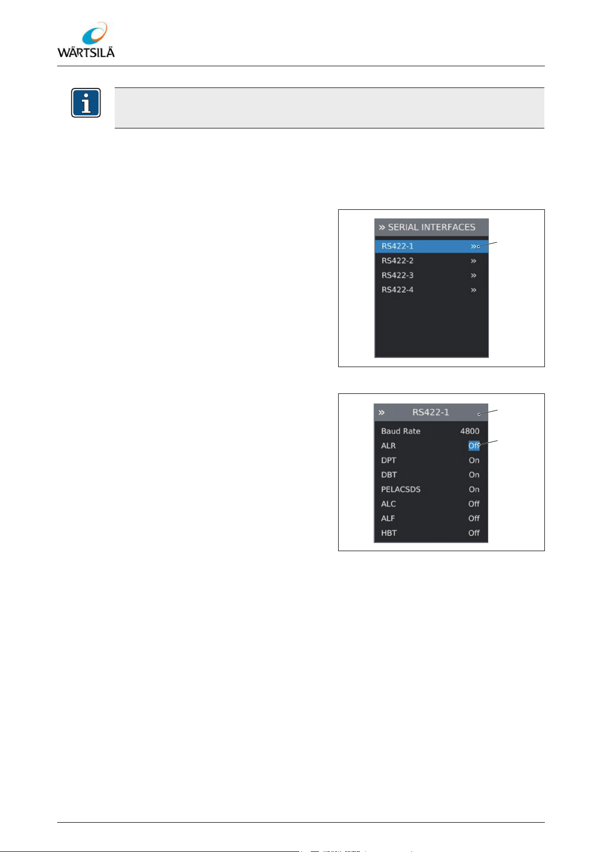
ELAC LAZ5200 – Operating Instructions
Operation
The serial interfaces are operated with 8-N-1 (8 data bits, no parity, 1 stop bit). This setting cannot be changed.
Configuring the interface
Precondition:
The “SERIAL INTERFACES” menu is unlocked 6.5.4.4.
Proceed as follows to configure an interface:
1. Navigate to the menu MAIN MENU >
SERIAL INTERFACES and select the
desired interface .
2. Press the [ENTER] key.
3. In the menu of the selected interface, select the desired menu item .
4. Press the [ENTER] key.
5. Select the desired setting with the
[CURSOR] keys (up or down).
6. Press the [ENTER] key to confirm the
selection.
7. If necessary, repeat the process for all
the other menu items.
Fig. 6.69: Configuring the Interface
Fig. 6.70: Configuring the Interface
98 / 134 Wärtsilä ELAC Nautik GmbH TH 526148001 EN Rev. A 09/2018
Refer to protection notice ISO 16016
 Loading...