

Page 1
Installation instructions
Range hood DIPQG10/DIPQG12
Island hood
Operating mode: Extraction/recirculation
The appliance should be installed by qualified personnel only.
Each step must be carried out and checked in full in the order specified.
Validity
These installation instructions apply to:
63004 (DIPQG9, construction width 100 cm)
63005 (DIPQG12, construction width 120 cm)
H4.2608 (motor housing, extraction, standard)
H4.2604 (motor housing, recirculation, standard, island and wall hood)
H4.2605 (motor housing, recirculation, short, island and wall hood)
H4.2774 (motor housing, extraction with options connection)
General notes
If other firing systems are being used at the same time (e.g. wood, gas, oil or coal-fired heating appliances), safe operation is
only possible providing a room negative pressure of 4 Pa (0.04 mbar) is not exceeded at the location of the appliance.
Risk of toxic fumes! An adequate flow of fresh air must be guaranteed e.g. via non-closable openings in doors or windows
and in combination with an air-intake/exhaust-air wall box or by other technical means.
J63004.113-0
02.09.14
If the appliance is installed over hobs, each cooking zone must be fitted with an ignition fuse and the minimum distances
(see 'Dimensions') must be adhered to.
Efficient repairs can only be guaranteed if it is possible to uninstall the complete appliance at any time without causing any
damage.
Identification plate
Remove the grease filters. The identification plate is located on the inside of the appliance.
Supplied installation accessories
All fixing elements are contained in the scope of delivery.
Extraction mode
The extracted air must not be fed into a chimney which is used for exhausting fumes from appliances burning gas or other
fuels.
Observe the local fire regulations.
1
Page 2
N
L1
L
X
L
N
Installation instructions
Range hood DIPQG10/DIPQG12
Island hood
Operating mode: Extraction/recirculation
Electrical connections
Electrical connections must be carried out by qualified personnel in accordance with the guidelines and standards for lowvoltage installations and the specifications of the local electricity supply companies.
A plug-in appliance may only be connected to a socket outlet with earthing contact, installed according to specifications. An
all-pole mains isolating device with 3 mm contact opening should be provided in the house wiring system. Switches, plug
and socket devices, circuit breakers and fusible cut-outs which are accessible after installation and which have all-poles
switching are permissible as isolating devices. Effective earthing and separately installed neutral and earth conductors
ensure safe and fault-free operation. After installation, live parts and cables with basic insulation must not be accessible.
Check old installations.
The appliance is designed for use up to a max. altitude of 2000 m above sea level.
Refer to the identification plate for information on the required mains voltage, current type and fuse protection.
Do not cut off the plug.
J63004.113-0
02.09.14
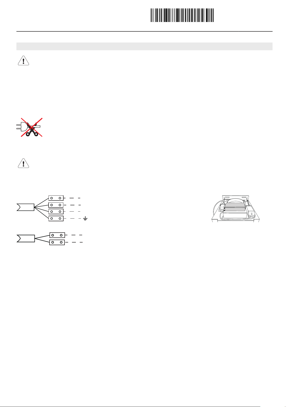
Options connection
The option may not be connected from a second side with mains voltage.
View X
Options connection
N (blue) = Neutral conductor
L1 (brown) = Control line (switched pole conductor)
L (white) = Pole conductor
(yellow/green) = Earth conductor
Window connection
L (black) = Pole conductor
N (red) = Neutral conductor
2
Page 3

70
B A
ø
150
1000/1200
700
h
X
330
330
¹
324,8
297
240,4
180
80
240,4
293,5
324,8
20
180
55
100
R80
Installation instructions
Range hood DIPQG10/DIPQG12
Island hood
Operating mode: Extraction/recirculation
Dimensions
J63004.113-0
02.09.14
Drilling plan (view X)
Telescopic casing
Distance above hob
(available in various heights) Minimum distance B:
Height A: See planning aid for kitchen appliances For electric hob: min. 500 mm
h:Extraction/recirculation 2.5 kg: 435 mm
For gas hob: min. 650 mm
Extraction with metal ring: 492 mm
Recirculation 5 kg: 580 mm
3
Page 4

S1
S1
A
B
L
S2
S2
Installation instructions
Range hood DIPQG10/DIPQG12
Island hood
Operating mode: Extraction/recirculation
Installation
Note on installation
• Ensure the correct layout of the exhaust air duct as well as an adequate supply of intake air.
Exhaust air requires intake air.
• Avoid routing the exhaust air pipeline to the side through the flue casing.
• Planning features for non-destructive de-installation and maintenance of the appliance.
– Do not route telescopic casing in suspended ceilings.
– Avoid silicon joints between the telescopic casing and the appliance.
– All plastering, plasterboarding, wall papering or painting work is to be carried out prior to installing the appliance.
Installing
J63004.113-0
02.09.14
4 × S1 (M4 × 15 mm)
36 × S2 (ø 3.5 × 6 mm)
6 × S3 (ø 5 × 40 mm)
1. Align motor housing A so cables L are at the front. Put
motor housing A on hood body B. Ensure that no
cables are trapped.
WARNING: Protect the glass cover!
2. Screw 2 screws S1 (M4 × 15 mm) to both the front
side and the back side of the motor housing A.
3. Lay hood on its back. Open glass cover, supporting it.
4. Remove grease filter.
5. Screw 6 screws S2 (ø 3.5 × 6 mm) in hood body B.
4
Page 5

BS
E
BS
BS
I
F
Q
G
H
S2
Installation instructions
Range hood DIPQG10/DIPQG12
Island hood
Operating mode: Extraction/recirculation
6. Connect flat-pin plug for operation and small 2-pin
plug for lights. 2 plug connector pairs must be
connected in total.
WARNING! Do not remove dummy connector BS
of third cable as function relevant.
J63004.113-0
02.09.14
7. Stow away cable in hood body and mount plug cover
E with 4 screws S2 (ø 3.5 x 6 mm).
8. Close glass cover, upright hood and determine hood
height G.
WARNING: Protect the glass cover!
9. Fix structure F with 12-16 screws S2 (ø 3.5 × 6 mm).
Pay attention to hood height G and alignment of structure F, the cut-outs must be laterally aligned. If blowout opening should be at front and back, the structure
must be turned accordingly. If possible, install bracing
ring Q in structure F.
10. Lay flue casing H over structure F. Ensure correct
positioning of outlet opening.
For recirculation mode:
Adjust air outlet grille of upper casing to face upwards.
Air outlet grille must be in front of blow-out opening.
For extraction mode:
Adjust air outlet grille of upper casing to face down-
wards.
11. Fix exhaust air hose to exhaust air connector. If nonreturn valve flap is used, test after installation to see if
functioning properly; use metal ring if needed.
12. Only for recirculation mode:
Connect diverter piece l to exhaust air hose and lay in
the structure.
5
Page 6

K
S3
K
M
S2
S2
S2
S2
S2
S2
Installation instructions
Range hood DIPQG10/DIPQG12
Island hood
Operating mode: Extraction/recirculation
J63004.113-0
02.09.14
13. Attach paper template – aligned with the middle of the
hob – to the ceiling. Ensure correct alignment. Make
drill holes for suitable screw mounting as per the
manufacturer’s instructions. See package leaflet.
14. Fit metal support K on the 4 screws S3 and secure
with the nuts.
15. Fit hood on the 2 hooks M of the metal support K
(ensure correct alignment).
16. Swing up hood and fix with 8 screws S2 (ø 3.5 ×
6 mm).
17. For recirculation mode:
Fix diverter piece I with 4 screws S2 (ø 3.5 × 6 mm).
For extraction mode:
Connect exhaust air hose to exhaust air pipe.
18. Make electrical connection (see section on 'Electrical
connections').
19. Raise upper flue casing H and fix with 2 screws S2 (ø
3.5 × 6 mm).
20. ATTENTION! The combi filter is separately packaged.
21. Insert grease filter.
22. Carry out function test.
6
 Loading...