

Page 1

MAPK-302E
DISSOLVED
OXYGEN
METER
Operation Manual
Nizhny Novgorod
2010
АЯ 7
4
Page 2

2
VZOR will appreciate any suggestions and comments aimed
at product quality improvement.
If you have any trouble with the instrument performance,
please contact us in writing or by phone.
Postal address: 603106, Russia, Nizhny Novgorod, POB 253
Telephone: + 7 (831) 229-65-67, 412-29-40
Website: www.vzornn.com
Page 3

3
C O N T E N T S
1 DESCRIPTION AND OPERATION ....................................................................... 4
1.1 Purpose ............................................................................................................ 4
1.2 Basic parameters ............................................................................................. 4
1.3 Specifications ................................................................................................... 6
1.4 Product components ........................................................................................ 7
1.5 Description and operation ................................................................................ 7
1.6 Measuring instruments, tools and accessories .............................................. 10
2 INTENDED USE .................................................................................................. 11
2.1 Operating limitations ...................................................................................... 11
2.2 Safety ............................................................................................................. 11
2.3 Pre-starting procedures ................................................................................. 11
2.4 Measurement procedure ................................................................................ 17
2.5 Functional check ............................................................................................ 20
2.6 Troubleshooting ............................................................................................. 20
3 MAINTENANCE ................................................................................................... 27
4 DELIVERY SET ................................................................................................... 27
APPENDIX A. Solubility of 100 % humidity air oxygen in distilled water,
depending on the temperature ............................................................................ 28
Page 4

4
1 DESCRIPTION AND OPERATION
1.1 Purpose
1.1.1 Product name and designation
MAPK-302E dissolved oxygen analyzer
TU 4215-022-39232169-2008.
1.1.2 The analyzer has been designed to measure the dissolved oxygen
concentration and water temperature.
1.1.3 The analyzer may be used to measure the mass concentration of water-dissolved oxygen and temperature of surface, waste and drinking water, and
may be employed by fish farms; chemical, biotechnological and food industries;
educational institutions and ecology branches.
1.1.4 The type of analyzer:
amperometric;
with external poling voltage;
with one sensitive element;
with a digital LCD display;
with automatic temperature compensation;
with dip sensor;
with automatic calibration when the sensor is placed in the oxygen envi-
ronment (air) at temperatures varying between +15 °С and +35 °С;
with automatic adjustment for atmospheric pressure during calibration.
1.2 Basic parameters
1.2.1 By resistance to climatic effects, the analyzer version group is B4 in
accordance with GOST 12997-84.
1.2.2 By resistance to mechanical effects, the analyzer version is L1 in accordance with GOST 12997-84.
1.2.3 The converter unit degree of protection ensured by the casing is IP30
in accordance with GOST 14254-96.
1.2.4 By resistance to atmospheric pressure, the analyzer version group is
Р1 in accordance with GOST 12997-84 (atmospheric pressure between 84 and
106,7 kPa).
1.2.5 Analyzed water parameters:
temperature, °С ………………………………………………….…... 0 to +50;
pressure, MPa, max ……...………………………………..….……....… 0,05;
salt content, g/dm3 ……...………………………..………..……..…... 0 to 40;
Page 5

5
рН ……………………………………………………….…….….......... 4 to 12;
rate of water flow relative to sensor membrane, cm/s ….…………...…... 5.
1.2.6 Permissible concentrations of unmeasured components:
dissolved ammonia, mg/dm3, max ….…...…………………..……….... 40,0;
dissolved phenol, mg/dm3, max ….………….………………..…………. 0,2;
dissolved sulphuretted hydrogen, mg/dm3, max …………….…………. 0,5;
dissolved chlorine, mg/dm3, max …………….…………………….……. 4,0.
1.2.7 Operating conditions:
ambient air temperature, °C ……………………………...………... +1 to +50;
relative air humidity at 35 °С and lower temperatures without moisture
condensation, %, max …………………….………................................................. 80;
atmospheric pressure, kPa (mm hg) ……………..………..….. 84,0 to 106,7
(630 to 800).
1.2.8 The analyzer is calibrated by air of 100 % humidity.
Calibration temperature range, °С ………………………………..… +15 to +35.
1.2.9 The analyzer is powered from a 2,2-3,4 V DC self-contained power
supply (two AA-type alkaline batteries).
1.2.10 Power consumption (at a rated voltage of 2,8 V), mW, max ….…... 10.
1.2.11 The analyzer retains its characteristics within the ranges set in the
analyzer specifications after replacement of the sensor’s spare parts, batteries and
calibration.
1.2.12 The overall dimensions and weights of analyzer components are
summarized in Table 1.1 below.
Table 1.1
Name and designation of component versions Overall dimensions,
mm, max
Weight,
kg, max
ВР29.01.000-01 converter unit 84×160×38 0,30
ВР29.02.000-01 oxygen sensor
(without cable)
14×115
0,10
ВР29.03.000 protective cap
20×90
0,05
1.2.13 GOST 12997-84 conditions for carriage in shipping containers:
temperature, °С ……………………...............…………..….…. – 20 to +50;
relative air humidity at 35 °С, % ............................…….....………...… 95±3;
5-35 Hz sinusoidal vibration with a 0,35 mm shift amplitude in the direction
marked “Top” on the package.
Page 6

6
1.3 Specifications
1.3.1 DOC (dissolved oxygen concentration) measuring range at an analyte
temperature of 20 °С, mg/dm3 ..………………………………….……..….. 0 to 10,00.
The upper limits of DOC measuring range, depending on the analyte tem-
perature, are shown in Table 1.2.
Table 1.2
t, °C 0 5 10 15 20 25 30 35 40 45 50
DOC,
mg/dm
3
17,45 15,29 13,48 12,10 10,00 9,85 8,98 8,30 7,69 7,12 6,59
1.3.2 Limits of the analyzer allowable basic absolute error in DOC measurement at an analyte temperature of (20,0±0,2) °С and ambient temperature of
(20±5) °С, mg/dm3 ……………………………….…........................... ±(0,050+0,04С),
where С, here and hereafter, is a measured DOC value in mg/dm3.
1.3.3 Limits of the analyzer allowable additional absolute error in DOC
measurement due to a change in the ambient temperature, by each ±5 °С from the
normal temperature (20,0±0,2) °С, within the operating temperature range from 0
to +50 °С, mg/dm3 ……………………………………….….…………………. ±0,012C.
1.3.4 Limits of the analyzer allowable additional absolute error in DOC
measurement due to a change in the ambient temperature by each ±10 °С from
the normal temperature (20±5) °С, within the operating temperature range from +1
to +50 °С, mg/dm3 ….……….............................................................
±(0,001+0,002C).
1.3.5 . Limits of the analyzer allowable additional absolute error in DOC
measurement at surplus pressure of analytical environment up to 0,2 MPa,
mg/dm3……………………………………………………………………………… ±0,1C.
1.3.6 Limits of the analyzer allowable absolute error in DOC measurement at
an analyte temperature coinciding with the calibration temperature which varies between +15 °С and +35 °С, at an ambient temperature of (20±5) °С,
mg/dm3……….…………………………………………....................... ±(0,050+0,04C).
1.3.7 Analyte temperature measuring range, °С ……...……............. 0 to +50.
1.3.8 Limits of the analyzer allowable basic absolute error in analyte temperature measurement at an ambient temperature of (20±5) °С, °C ….……...…... ±0,3.
1.3.9 Limits of the analyzer allowable basic absolute error in analyte temperature measurement due to a change in the ambient temperature by each ±10 °С
from the normal temperature (20±5) °С, within the operating temperature range
from +1 to +50 °С, °С …….....………………………..…………….…………..….. ±0,1.
1.3.10 Limit of the permissible value of the analyzer readout setting time t
0.9
in DOC measurement, min …………..……….………………………….…………… 1.
1.3.11 Limit of the permissible value of the analyzer readout setting time tу in
DOC measurement, min ……….…………......................…………..……………….. 2.
1.3.12 Limit of the permissible value of the analyzer readout setting time t
0.9
in analyte temperature measurement, min ……………………….………….………. 1.
Page 7

7
1.3.13 Limit of the permissible value of the analyzer readout setting time tу in
analyte temperature measurement, min ………………………………………….….. 3.
1.3.14 Analyzer oscillatory readings in DOC measurement for 8 h, mg/dm3,
max …………………………………………………..……………...….. ±(0,025+0,02C).
1.4 Product components
The analyzer comprises:
converter unit;
oxygen sensor with a 5 m connecting cable;
protective cap.
1.5 Description and operation
1.5.1 General analyzer data
The MAPK-302E dissolved oxygen analyzer is a small-size microprocessor
device designed to measure the mass concentration of water-dissolved oxygen
(DOC) and the analyte temperature.
The DOC values measured in mg/dm3 or temperature measured in Celsius
degrees (depending on the measuring mode) are displayed on the readout device
– a digital LCD display (“the display”). The minimum value of the least significant
digit for DOC measurement is 0,001 mg/dm3. The least significant digit value for
temperature measurement is 0,1 °С.
The analyzer is calibrated by atmospheric air of 100 % humidity with auto-
matic adjustment for atmospheric pressure during calibration.
Adjustment for atmospheric pressure during the analyzer calibration by at-
mospheric air is provided by a built-in atmospheric pressure sensor.
Note – The DOC values may be displayed in % O2 (in % saturation) with the
least significant digit value of 0,1 % O2.
Page 8
8
1.5.2 Analyzer operating principle
The analyzer uses an amperometric sensor operating as a closed-type
polarographic cell. The electrodes are submerged in an internal electrolyte solution
which is separated from the analyte by a membrane penetrable for oxygen but impenetrable for liquid and water vapor. From the analyte, oxygen diffuses through
the membrane into a thin layer of electrolyte between the electrodes and the membrane and undergoes an electrochemical reaction on the surface of the cathode
which is polarized by external voltage applied cross the electrodes. In the process,
the sensor generates a DC signal which is at a fixed temperature proportional to
DOC in the analyte.
The analyzer features a temperature sensor (platinum thermal resistor) to
measure temperature and to automatically compensate for the temperature dependence of the oxygen sensor signal. The temperature sensor signal is supplied
to the ADC input.
The ADC converts signals of the oxygen sensor and the temperature sensor
into codes incoming the microcontroller.
The microcontroller processes the codes received and shows the information
on the digital LCD display.
1.5.3 Analyzer design
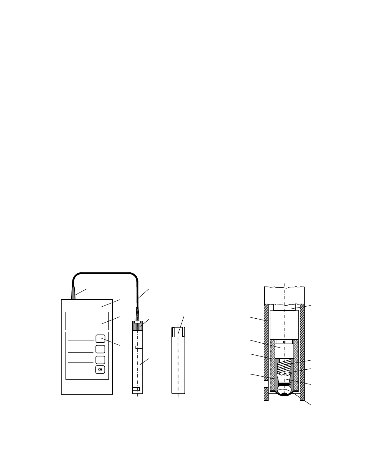
The analyzer is shown in Fig.1.1а.
а b
Fig. 1.1
1
3
15
2
4
5
12
11
13
14
8
9
10
7 16
17
MODE CAL ENTER
6
Page 9

9
Converter unit 1 has a sealed plastic housing and is designed to convert signals from oxygen sensor 2 and display measurement data.
The front panel of the converter unit features:
indicator screen 3 designed to display a measured DOC value or temper-
ature (depending on the chosen measuring mode), battery charge and current time
(in off state);
button 4.
The back panel of the converter unit features a battery compartment cover.
Located on top of the converter unit is sealed cable entry 5 for oxygen sensor 2.
For transportation use protective cap 6.
Fig.1.1b shows the oxygen sensor design.
The sensor’s basic functional elements are platinum cathode 7 and silver
anode 8. Secured to cathode 7 with caprone thread 9 is teflon film 10. The membrane and rubber bushing form membrane assembly 11 fitted over bushing 12 and
filled with electrolyte 13. The temperature sensor is enclosed in case 14. Protective
bushing 15 covers the sensor electrode portion and is screwed into cable bushing
16 (Fig.1.1а).
Cable 17 connects the sensor electrode assembly to the converter unit.
Protective cap 6 is made of plastic, it is cylindrical form with slots and should
be put on protective bushing 15.
1.5.4 Functions of buttons on the converter unit front panel
The analyzer front panel features the following buttons as shown in Fig.1.1а:
the button for analyzer power on/off. When the analyzer is energized,
the display shows the measured DOC or temperature value;
the MODE button enables the DOC or temperature measuring mode, with
the display showing the measured DOC or temperature value and mg/dm3 or °С
character, respectively, coming on in the right half of the indicator. If indicating in %
saturation, in the right side of display is shown the sign “%”;
the CAL button selects the analyzer calibration mode. When pressed se-
quentially, the button causes the characters с0 (analyzer reset) and с1 (atmospheric air calibration) to light up on the display;
the ENTER button confirms the selected calibration mode and completes
calibration.
Page 10

10
1.6 Measuring instruments, tools and accessories
1.6.1 The following tools and accessories, which are not included in the de-
livery set, will be additionally required for maintenance of the analyzer:
2 mm cross screwdriver;
В-1-250 beaker;
КН-100-19/26 flask;
hydroquinone, chemically pure;
sodium or potassium hydroxide, chemically pure.
Instead of hydroquinone, chemically pure and sodium or potassium hydroxide, chemically pure the following reagents may be used:
sodium sulphite Na2SO4, chemically pure;
potassium permanganate KMnO4, chemically pure.
Page 11

11
2 INTENDED USE
2.1 Operating limitations
2.1.1 The MAPK-302E analyzer version is used to measure DOC in
wastewater and surface water, including muddy and colored water with organic
pollutants.
2.1.2 Para.1.2.5 provides permissible concentrations for a number of components which affect measuring results.
2.1.3 The analyzer should be positioned so as to prevent water from getting
on the converter unit.
2.1.4 When using the analyzer, avoid hitting or dropping the oxygen sensor
to keep its glass components intact.
2.2 Safety
2.2.1 The analyzer should only be operated by personnel who are familiar
with this manual and chemical handling safety rules in accordance with
GOST 12.1.007-76 and GOST 12.4.021-75.
2.2.2 The analyzer meets the requirements of Safety Class III to
GOST R 52319-2005. The rated supply voltage varies between 2,2 and 3,4 V. No
protective earthing is required.
2.2.3 By electromagnetic compatibility, the analyzer meets the requirements
of GOST R 51522-99 for Class B equipment.
2.3 Pre-starting procedures
On receipt of the analyzer, unpack it, check the set for completeness and
make sure that the packed components are intact.
If kept in cold conditions before delivery, the analyzer should be held at room
temperature for at least one hour before setting-up procedures.
Page 12

12
2.3.1 Power supply connection
To connect the power supply, remove the battery compartment cover located
on the rear panel of the converter unit. Install two AA-type alkaline batteries observing the polarity marking inside the battery compartment. Replace the battery
compartment cover.
With a power supply installed in the battery compartment, the analyzer
can indicate time, when turned off. The dot between hours and minutes flickers at an interval of 1 s.
Time indication may be switched off and on again by pressing the MODE
button, with the analyzer off.
Proceed as follows to correct time:
press the CAL button, minutes will start blinking on the display;
use the MODE and ENTER buttons to set the minute value;
press the CAL button, hours will start blinking on the display;
use the MODE and ENTER buttons to set the hour value;
press the CAL button to complete time setting, the analyzer goes into the
time indication mode.
Switch on the analyzer and check if the display shows DOC or temperature
readings in mg/dm3 or % sat., or °С respectively.
WARNING: ALWAYS OBSERVE polarity when installing batteries. Failure to meet this condition may damage the analyzer!
When the display shows the sign, replace AA-type alkaline batteries.
2.3.2 Oxygen sensor setting-up procedures
Since the oxygen sensor from the analyzer set is delivered in the “dry” state,
it should be filled with electrolyte included with the delivery set, as described in para.2.6.3, and submerged in distilled water for a minimum of 8 h.
Make sure two AA-type alkaline batteries are installed in the converter unit.
Regardless of whether the analyzer is on or off, the sensor will receive polarizing
voltage needed to build up an electrode system.
Page 13

13
2.3.3 Analyzer functional check
The analyzer functional check includes:
analyzer precalibration by atmospheric air oxygen;
check of readings in the null solution.
It is recommended that the analyzer functional check be performed:
after filling the sensor with electrolyte on delivery of the analyzer;
after replacement of the membrane assembly or teflon film;
if there are any doubts as to the analyzer’s serviceability.
2.3.3.1 Analyzer precalibration
Take the sensor out of the vessel with water and place it horizontally (put on
the table).
Press the MODE button to enable the DOC measuring mode in mg/dm3. The
analyzer display will show a figure measured in mg/dm3.
Keep the sensor in the air for 5 min.
Press the CAL button twice. The analyzer display will show the c1 symbol
showing the entry into the outside air calibration mode.
Press the ENTER button. The analyzer display will show DOC readings corresponding to the table of 100 % humidity air oxygen solubility for analyzermeasured temperatures, with allowance for the atmospheric pressure at the time of
calibration, for example, c8.38 mg/dm3.
Wait at least 8 s before pressing the ENTER button once again. The donЕ
caption will appear shortly on the screen and the с symbol will go out. The analyzer
will go into the measuring mode, which means that precalibration is completed.
2.3.3.2 Reading check in the null solution
Prepare an oxygen-free (null) solution, and for this purpose:
prepare an alkali solution (KOH or NaOH), concentration 5 g/dm
3
;
pour it into a 0,3-0,5 dm
3
vessel so that its level is 50 to 60 mm;
add 0,3 to 0,5 g of hydroquinone and stir.
Uptime in air tight vessel is max 1 month.
Submerge the sensor, with its membrane down, in the solution and move it
to slightly agitate the solution in order to prevent air bubbles from amassing on the
Page 14

14
membrane. The displayed analyzer reading should decrease slowly.
Take the analyzer readings in 10 min.
They should vary within ±50 µg/dm3.
With the above procedure successfully completed, the analyzer is ready for
normal service. The analyzer calibration by outside air shall then be performed as
per para.2.3.4.
If the readings do not decrease to the specified level, a sensor cycling operation should be carried out as per para.2.3.3.3.
Note – To check measurements in the null solution other reagents may be
used.
To do so:
prepare sodium sulphite solution Na2SO3, concentration 10 g/dm3;
pour it into a 0,3-0,5 dm3 vessel so that its level is 50 mm;
prepare potassium permanganate solution KMnO4, concentration 5 g/dm3;
add 2-3 cm3 of KMnO4 solution in Na2SO3 solution and stir.
Period of validity: 2-3 h.
2.3.3.3 Sensor cycling
Proceed as follows to carry out the cycling operation:
switch on the analyzer;
prepare a null solution as per para.2.3.3.2;
submerge the sensor, with its membrane down, in the solution and move
it to slightly agitate the solution in order to prevent air bubbles from amassing on
the membrane;
hold the sensor in the null solution for 5 min, then take it out, shake off the
solution drops from the membrane and hold it in the air for 5 min;
repeat the null solution − air cycle 3-4 times;
submerge the sensor in null solution again;
take the analyzer reading in 10 min; it should be within ±50 µg/dm3.
If the above steps fail to cause the analyzer readings in the null solution to
decrease to the desired values, this suggests either bad quality of the null solution
(bad reagents) or a fault in the analyzer (see section 2.6 Troubleshooting).
Calibration of the analyzer should then be performed subject to para.2.3.4 or
2.3.5.
If any error character (Е3, Е4, Е5, Е6, Е7, Е8, Е9) is displayed during the
analyzer functional check, also refer to section 2.6.
Page 15
15
2.3.4 Analyzer calibration by outside air
Outside air calibration of the analyzer should be performed:
when the device is new;
once a shift (8 h);
after replacement of electrolyte, membrane and teflon film.
Calibration of the analyzer is performed in the outside air at temperatures between +15 °С and +35 °С and a 100 % relative humidity. It is more convenient to
perform calibration at room temperature.
Prior to calibration, the analyzer, with AA-type alkaline batteries installed,
should be held at room temperature for at least 1 h. The analyzer may be left
switched on. Submerge the sensor fully in distilled water of room temperature for a
minimum of 10 min.
Rinse the sensor in distilled water, shake off water drops from the sensor
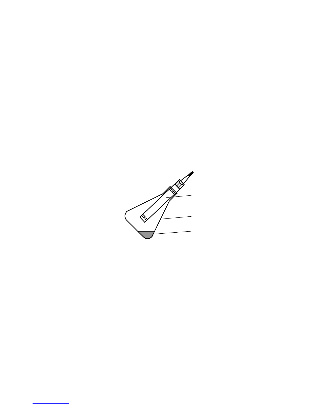
membrane and put the sensor in the cone flask with a water layer 3 to 5 mm, as
shown in Fig.2.1. Position the flask at an angle of 30 to 45° to the horizontal for the
remaining water to flow off the membrane.
Fig. 2.1 − Position of the sensor inside the flask for analyzer calibration
Wait for 10 min before performing the outside air calibration steps which follow.
1 Press the CAL button twice. The c1 character will appear on the display,
showing the entry into the outside air calibration mode.
2 Press the ENTER button. The analyzer will display DOC readings corresponding to the table of 100 % humidity air oxygen solubility for analyzer-measured
temperature, with allowance for the atmospheric pressure at the time of calibration,
e.g. c8.38 mg/dm3.
3 Wait at least 8 s before pressing ENTER once again. The donЕ caption
will briefly appear on the display and the analyzer will go into the measuring mode.
It means the outside air calibration mode is completed and the analyzer is calibrated.
Sensor
Water
Flask
Page 16

16
Once calibrated by outside air, the analyzer is ready for use.
Note − Outside air calibration of the analyzer may be cancelled before Step
3 by pressing MODE. The analyzer will go into the DOC measuring mode, retaining
the values of previous calibration coefficients.
2.3.5 Analyzer zero calibration
Analyzer zero calibration allows the sensor residual zero current to be compensated within narrow limits (–3,0 to +3,0 µg/dm3).
Proceeds as follows prior to carrying out this operation:
switch on the analyzer;
prepare a fresh null solution as per para.2.3.3.2;
enable the DOC measuring mode in mg/dm3;
perform cycling operations as per para.2.3.3.3;
hold the sensor in the air for 5 min, submerge the sensor, with its mem-
brane down, in the null solution and move it to slightly agitate the solution in order
to prevent air bubbles from amassing on the membrane;
hold the sensor in the null solution for at least 40 min.
Perform the following steps to set the analyzer zero.
1 Press CAL. The analyzer display will show the с0 caption.
2 Press ENTER. The analyzer display will show DOC Z0 readings in the null
solution without allowance for zero adjustment, e.g. с.002 mg/dm3.
3 Wait at least 8 s before pressing ENTER once again. The donЕ caption
will briefly appear on the display and the analyzer will go into the measuring mode.
The analyzer display will indicate a DOC value in the null solution after analyzer
zero setting:
0,000; if −0,003 mg/dm
3
≤ Z0 ≤ 0,003 mg/dm3;
Z
0
−0,003; if Z0 > 0,003 mg/dm3;
Z
0
+0,003; if Z0 < −0,003 mg/dm3.
Note − Analyzer zero setting may be cancelled before Step 3, by pressing
MODE. The analyzer will go into the DOC measuring mode, retaining the values of
previous calibration coefficients.
Page 17

17
2.4 Measurement procedure
2.4.1 Measurements in reservoir
Before measuring in reservoir it is important to put protective cap off and
submerge the probe in the analyte reservoir as deep, as important. Permit water
flow, moving the probe up and down with azimuth angle of 10-15 cm once in 2-5 s
(if there is a water flow in the reservoir, the probe may be motionless). After measurements are determined, fix the values in mg/dm3 or % saturation.
2.4.2 Measurement of oxygen at depth up to 20 m.
Oxygen probe permits to measure dissolved oxygen at depth up to 20 m if
ordered cable extension. Due to rubber bushing, on which the membrane is fitted,
equalizes hydrostatic pressure of membrane assembly’s intracavity and ambient
medium. In addition the measurements stay constant if oxygen concentration is
constant, independent of hydrostatic pressure.
WARNING: Before measuring deeply check, that membrane assembly
is fully filled with electrolyte!
2.4.3 Measuring in standard BOD flask
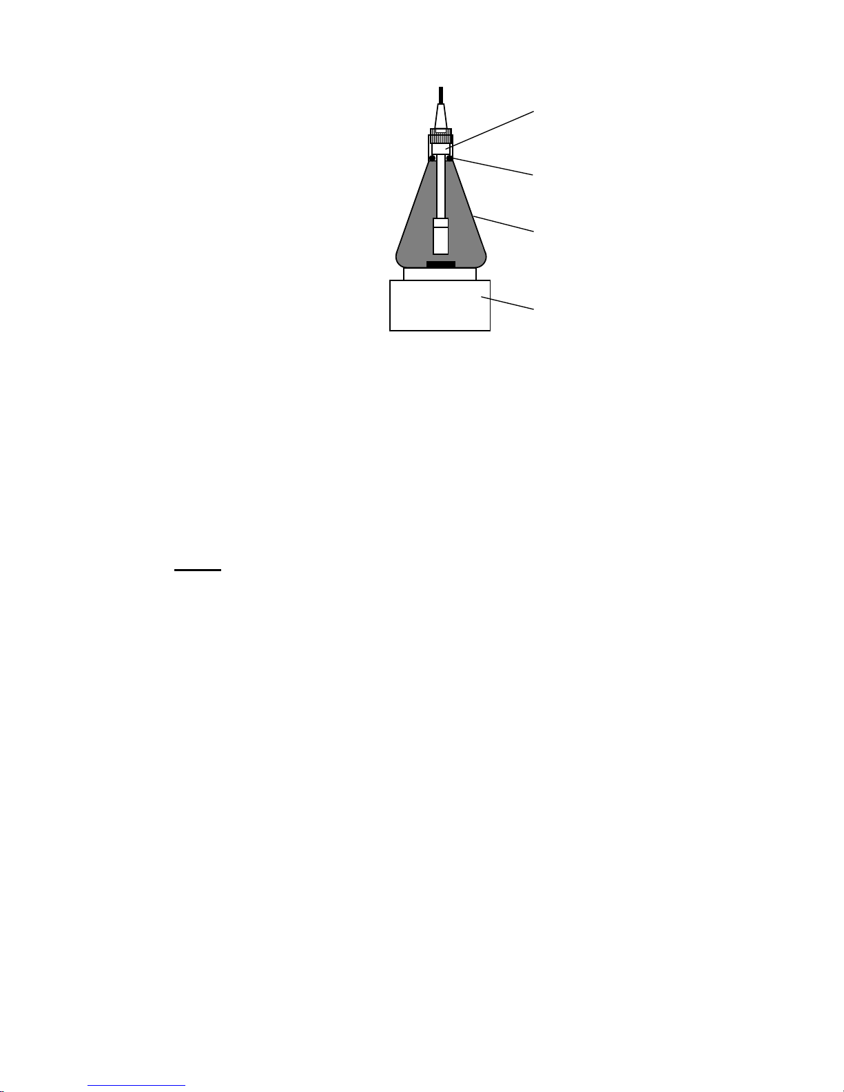
While measuring in standard oxygen BOD flask in accordance with fig. 2.2 it
is needed:
submerge the cane of stir bar in flask;
screw off protective bushing and take it off. Put the probe in the flask, firm-
ing it in the flask neck with rubber ring, installed on the measuring part of the
probe;
put the flask on the stir bar and turn it on.
Note – The rubber ring is not included in the meter kit and should be selected in accordance with flask’s size.
Page 18
18
Fig. 2.2
Turn the meter on. With button “MODE” choose indication of DOC in
mg/dm3 or % sat.
The speed of water flow of analyte water along the membrane should be min
5 cm/s. In stationary fluid the measurements would lower slowly.
The measuring process before getting the fixed value is max 2 min.
Notes
1 If the temperature of the probe and aquatic environment differs, the
readout setting time is 3-5 min.
2 If there is no stir bar, it is recommended to submerge in the flask glass or
plastic balls and stir arm circling the flask till the readout set (about 2 min).
If values of dissolved oxygen decrease slowly and do not set in admitted
time, then there may be air bubbles on the membrane. If so, it is important:
while measuring in reservoir, stir the probe harshly leaving it submerged in
the water;
while measuring in BOD flask, invert the flask with the probe in it and stir.
In viscous medium it is necessary to clean the membrane from time to time
(para.2.6.2).
2.4.4 Water temperature measurement
The temperature measurement mode t °С is enabled by pressing the MODE
button.
Probe
Rubber ring
Flask
Stir bar
Page 19

19
Allow for the analyzer readings to be set and record them as a measuring
result.
2.4.5 Calculation of dissolved oxygen concentration by analyzer read-
ings, with allowance for the salt content
When measuring DOC in salty water, use the correction factor α, by which
the analyzer readings should be multiplied. The α value is defined with the formula:
= 1−С
salt
ε,
where С
salt
salt content, g/dm3;
ε factor listed in Table 2.1.
Table 2.1. − Correction factors
t °C ε t °C ε t °C ε t °C ε t °C ε
0,0
0,0063
11,0
0,0057
21,0
0,0052
31,0
0,0048
41,0
0,0043
1,0
0,0063
12,0
0,0057
22,0
0,0052
32,0
0,0047
42,0
0,0042
2,0
0,0062
13,0
0,0057
23,0
0,0051
33,0
0,0047
43,0
0,0042
3,0
0,0062
14,0
0,0055
24,0
0,0050
34,0
0,0046
44,0
0,0041
4,0
0,0060
15,0
0,0055
25,0
0,0050
35,0
0,0046
45,0
0,0041
5,0
0,0060
16,0
0,0055
26,0
0,0049
36,0
0,0045
46,0
0,0040
6,0
0,0060
17,0
0,0054
27,0
0,0049
37,0
0,0045
47,0
0,0040
7,0
0,0060
18,0
0,0054
28,0
0,0049
38,0
0,0044
48,0
0,0039
8,0
0,0058
19,0
0,0053
29,0
0,0048
39,0
0,0044
49,0
0,0039
9,0
0,0058
20,0
0,0053
30,0
0,0048
40,0
0,0043
50,0
0,0038
10,0
0,0058
Exemplary calculation of correction factor :
Let С
salt
=10 g/dm3, t=20 °C,
thus ε =0,0053,
then =1-10·0,0053=0,947.
Note − This method for salt content correction is based on the International
Standard ISO 5814 Water Quality – Determination Of Dissolved Oxygen – Electrochemical Probe Method.
WARNING: while operating the analyzer:
keep the sensor membrane wet. The sensor (its membrane) should be
kept in distilled or boiled water during intervals between measurements.
transportation of the probe should be held with protective cap on it. In the
cap there is foam. The foam should be humid, so that one should fill the cap with
the water and then pour water out;
Page 20

20
when brought into a warm room from the cold air, prior to enabling, hold
the analyzer at room temperature for at least 1 hour in order for condensed moisture to evaporate.
2.5 Functional check
A serviceable analyzer should meet the following requirements:
with the sensor placed in the null solution, the analyzer readings stay
within ± 50 µg/dm3;
when outside air calibration is accomplished, (para.2.3.4) neither Е3 nor
Е4 is displayed on the screen and readings C
cal
, mg/dm3, are set with an accuracy
±1 % of the calculated value defined with the formula:
325,101
)(
2
atm
cal
Р
tСоС ,
where Со2(t solubility of 100 % humidity air oxygen in distilled water, at
temperature t, °С, and normal atmospheric pressure of 101,325 кPa as per Table A.1), mg/dm3;
Р
atm
atmospheric pressure as of the time of calibration, kPa.
2.6 Troubleshooting
2.6.1 The typical faults of the analyzer and remedial methods are summa-
rized in Table 2.2.
In case of troubles set out in Table 2.2, proceed as recommended in the
Remedy column, in accordance with the clauses given below and Fig.1.1 and 2.3.
Table 2.2
Trouble, symptoms Probable cause Remedy
1 With power on, no readings are displayed
Poor battery contact Open the battery com-
partment and clean con-
tacts
Supply voltage below
acceptable level
Para.2.3.1 Replace bat-
teries
2 With power on, all or random segments and characters illuminate on the
screen
Dead batteries Para.2.3.1. Replace bat-
teries
Page 21
21
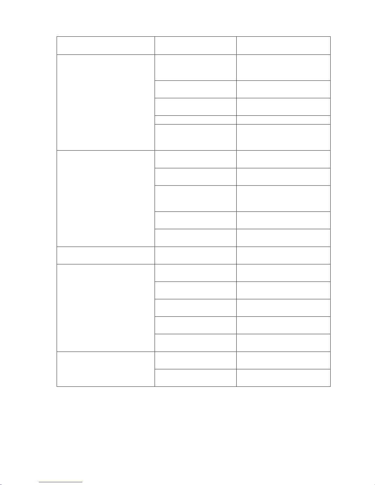
Table 2.2 (Continue)
Trouble, symptoms Probable cause Remedy
3 When the zero point of
measuring range is
checked, analyzer readings
go beyond ±0,050 mg/dm
3
Ruptured or punctured
membrane, sensor
seal failure
Para.2.6.3, 2.6.4. Replace
the membrane and elec-
trolyte
Moisture inside the
converter unit
Dry the converter unit for
3-4 days
Overstretched membrane
Para.2.6.4. Replace the
membrane assembly
Bad null solution Replace the null solution
Broken (cracked)
glass holder of sensor
electrodes
Factory repair
4 When the analyzer is calibrated by outside air, Е3
(sensor current below rating) is displayed.
Electrolyte has leaked
out
Para.2.6.3. Fill in electro-
lyte
Contaminated membrane
Para.2.6.2. Clean the
membrane
Dry membrane Keep the membrane in
water for 2-3 days without
dismantling the sensor
Defective membrane Para.2.6.4. Replace the
membrane assembly
Analyzer sensor off
the outside air
Position the sensor in air
5 Electrolyte leaking out
fast
Ruptured membrane Para.2.6.4. Replace the
membrane assembly
6.1 Sharp change in and
increased instability of analyzer readings.
6.2 During analyzer calibration by outside air, Е4 (excess sensor current) is displayed on the screen.
Ruptured membrane Para.2.6.4. Replace the
membrane assembly
Contaminated electrolyte
Para.2.6.3. Replace elec-
trolyte
Moisture inside the
converter unit
Dry the converter unit for
3-4 days
Ruptured teflon film Para.2.6.4. Replace teflon
film
Analyzer sensor off
the outside air
Position the sensor in air
7 Extended time of response to oxygen concentration variations
Contaminated membrane
Para.2.6.2. Clean the
membrane
Contaminated platinum electrode
Para.2.6.5. Clean the plat-
inum electrode
Page 22

22
Table 2.2 (Continue)
Trouble, symptoms Probable cause Remedy
8 During measurements,
Е5 (excess measured sensor current) is displayed on
the screen. Analyzer does
not respond to pressed buttons, except button
Ruptured membrane Para.2.6.4. Replace the
membrane assembly
Contaminated electrolyte
Para.2.6.3. Replace elec-
trolyte
Moisture inside the
converter unit
Dry the converter unit for
3-4 days
Ruptured teflon film Para.2.6.4. Replace teflon
film
Broken analyzer Factory repair
9 During measurements,
indication of exceeded display digit capacity appears
on the screen:
“Е6 mg/dm3”
readings less than minus
199,9 mg/dm3;
“Е7 mg/dm3” − readings
exceeding 199,9 mg/dm3.
Operator’s errors in analyzer calibrations
Para.2.6.6. Perform operations to set initial analyzer parameters
Broken analyzer Factory repair
10 During measurements,
Е8 is displayed on the
screen.
Faulty temperature
measuring channel
(heat probe breakage)
Factory repair
11
Е
9
is displayed on the
screen.
Writing error in
ЕЕРRОМ memory
Factory repair
2.6.2 Membrane cleaning
The sensor membrane may be cleaned with a wad of alcohol-soaked cotton.
The sensor membrane may also be submerged in a weak solution (2 %) of
sulfuric acid for about 1 h, and then wash it in running water.
2.6.3 Filling the sensor with electrolyte, electrolyte replacement
As it is supplied in a dry state (without electrolyte), the sensor needs to be
filled with electrolyte after its receipt from the manufacturer.
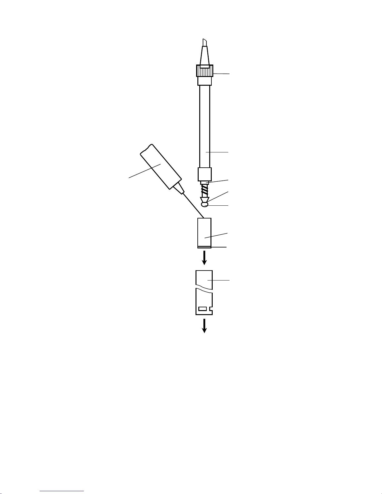
Unscrew and remove the protective bushing from the sensor as per Fig.2.3.
Page 23
23
Fig. 2.2 − Dismantling the sensor for filling and replacement of electrolyte,
replacement of teflon film and membrane assembly
Remove the membrane assembly from the bushing. Draw electrolyte from
SPK into a syringe. Take the membrane assembly and, holding it with the membrane down, inject electrolyte to fill two thirds of the volume, taking care to avoid
damaging the membrane. While continuing to keep vertical the membrane assembly filled with electrolyte, set it on the bushing against the stop. Screw in the protective bushing.
Cable bushing
Protective bushing
Bushing
Remove
Syringe
filled with
electrolyte
Membrane assembly
Case
Capron thread
Teflon film
Membrane
Remove
Page 24

24
WARNING: The membrane should be stretched and pressed firmly
against the sensor platinum cathode. The membrane SHALL NEVER separate
from the cathode!
After a certain period of service, the sensor may have the volume of electrolyte reducing due to leakage through pinholes or ruptures in the membrane, which
necessitates electrolyte replacement.
Remove the membrane assembly from bushing 6, drain the remaining electrolyte and wash the assembly with distilled water. Fill the membrane assembly
with new electrolyte.
Electrolyte composition: KCl, chemically pure – 14 g; KOH, chemically pure –
0,2 g; versene – 0,15 g; distilled water – up to 0,1 dm3. Filter the solution.
2.6.4 Replacement of the membrane assembly and teflon film
2.6.4.1 Replacement of the membrane assembly may be necessary in case
of mechanical damage (cracks, ruptures) or overstretching of the membrane. A
faulty membrane manifests itself in analyzer reading instability, high analyzer readings in the null solution and longer time of response during DOC measurement.
Unscrew and remove the protective bushing from the sensor as per Fig.2.3.
Remove the membrane assembly form the inner case and drain the electrolyte.
Check the teflon film for damage.
The film should be firmly pressed against the cathode, in a wrinkle-free man-
ner. Damaged film should be replaced.
Once the teflon film is removed, check the sensor electrode to see if they
look as follows:
platinum cathode 1 (Fig.1.1b) sealed in a glass tube should be clean;
silver anode 2, coiled over the tube should be gray.
If necessary, clean the electrodes with a wad of alcohol-soaked cotton.
WARNING: NEVER use any abrasive for cleaning electrodes!
2.6.4.2 Damaged teflon film should be replaced with new one from spare
parts kit. To do this, place it on the cathode, press the film edges firmly against the
side surface of the glass tube and, holding the edges by hand, wind around 5-6
laps of caprone thread making 2-3 knots. Cut off with scissors surpluses of teflon
film not closer than 3-5 mm from caprone.
WARNING: NO rupture or hole in teflon film in the platinum cathode ar-
ea are permissible!
Page 25

25
Take a new membrane assembly from SPK and, holding the assembly vertically, fill electrolyte with it. Then carefully fit the assembly with electrolyte over the
bushing and place the protective bushing.
After membrane assembly/teflon film replacement, perform the steps detailed in para.2.3.3 and 2.3.4.
2.6.5 Platinum electrode cleaning
A need for platinum electrode cleaning in a special solution arises in
6-12 months after the first use. It is not recommended to clean the electrode before
this period expires.
To clean the electrode, prepare two solutions.
Solution composition:
Solution1: chlorohydric acid (concentrated) − 50 cm3,
distilled water up to 100 cm3;
Solution 2: acetic acid (80 to 100 %).
Pour the solutions into vessels making sure that the liquid level is up to
3 mm. Then proceed as follows:
remove the teflon film;
wash the sensor with distilled water;
place the sensor into a vessel with Solution 1 and hold it there for 1 h;
wash the sensor with distilled water;
place the sensor into a vessel with Solution 2 and hold it there also for
1 h;
WARNING: NEVER PLACE the silver anode in the above solutions!
wash the sensor with distilled water.
Then proceed to para.2.6.4.2.
2.6.6 Analyzer initial parameter setting
The instrument features a mode for setting the analyzer initial parameters of
shift (zero shift) and slope corresponding to the averaged sensor. This mode enables calibration to be always performed from the fixed initial conditions.
Use this mode when in doubt as to whether the analyzer has operated cor-
rectly in performing calibration modes.
Page 26

26
2.6.6.1 Zero shift setting
1 Switch off the analyzer.
2 Press the CAL button and, keeping it pressed, switch on the analyzer. Af-
ter a sound signal release the CAL button. The screen will display с2.
3 Press the ENTER button. The donЕ capture will briefly appear on the
screen and the analyzer will go into the measurement mode. The display will indicate readings in mg/dm3 with zero shift.
2.6.6.2 Average slope setting
1 Switch off the analyzer.
2 Press the CAL button and keeping it pressed, switch on the analyzer. Af-
ter a sound signal release the CAL button. The screen will display с2. Press the
CAL button again. The screen will display с3.
3 Press the ENTER button. The donЕ capture will briefly appear on the
screen and the analyzer will go into the measurement mode. The display will indicate readings in mg/dm3 corresponding to the average sensor slope.
Once the analyzer initial parameters are set, proceed to para.2.3.4.
Page 27

27
3 MAINTENANCE
Maintenance of the analyzer comprises:
analyzer calibration by outside air (para.2.3.4) to be carried out every 8 h;
analyzer zero calibration (para.2.3.5) to be carried out every three
months;
sensor cycling (para.2.3.3.3) to be carried out when the analyzer has not
been in use for more than 24 hours. This operation ensures the highest response
rate of the instrument in DOC measurements.
When the conditions described in para.2.5 are fulfilled, the analyzer meets
the specifications listed in para.1.3.
4 DELIVERY SET
4.1 The delivery set is shown in Table 4.1.
Table 4.1
Description Quantity
1 MAPK-302E dissolved oxygen analyzer
(with probe, cable length 5 m)
1
2 Protective cap 1
3 Spare parts kit (to oxygen probe) 1
4 Tool and accessory kit 1
5 Tool and accessory kit 1
6 Operation Manual 1
Page 28

28
APPENDIX A
(reference)
Solubility of 100 % humidity air oxygen in distilled water, depending on the
temperature
Р
atm
=101,325 кPa
Table A.1 mg/dm
3
t, °С 0 0,1 0,2 0,3 0,4 0,5 0,6 0,7 0,8 0,9
0 14,62 14,58 14,54 14,50 14,46 14,42 14,38 14,34 14,30 14,26
1 14,22 14,18 14,14 14,10 14,06 14,02 13,98 13,94 13,90 13,87
2 13,83 13,79 13,75 13,72 13,68 13,64 13,60 13,57 13,53 13,49
3 13,46 13,42 13,39 13,35 13,32 13,28 13,24 13,21 13,17 13,14
4 13,11 13,07 13,04 13,00 12,97 12,93 12,90 12,87 12,83 12,80
5 12,77 12,74 12,70 12,67 12,64 12,61 12,57 12,54 12,51 12,48
6 12,45 12,41 12,38 12,35 12,32 12,29 12,26 12,23 12,20 12,17
7 12,14 12,11 12,08 12,05 12,02 11,99 11,96 11,93 11,90 11,87
8 11,84 11,81 11,79 11,76 11,73 11,70 11,67 11,64 11,62 11,59
9 11,56 11,53 11,51 11,48 11,45 11,42 11,40 11,37 11,34 11,32
10 11,29 11,26 11,24 11,21 11,18 11,16 11,13 11,11 11,08 11,06
11 11,03 11,00 10,98 10,95 10,93 10,90 10,88 10,85 10,83 10,81
12 10,78 10,76 10,73 10,71 10,68 10,66 10,64 10,61 10,59 10,56
13 10,54 10,52 10,49 10,47 10,45 10,42 10,40 10,38 10,36 10,33
14 10,31 10,29 10,27 10,24 10,22 10,20 10,18 10,15 10,13 10,11
15 10,08 10,06 10,04 10,02 10,00 9,98 9,96 9,94 9,92
9,90
16 9,87
9,85 9,83 9,81 9,79
9,77 9,75 9,73 9,71
9,69
17 9,66
9,64 9,62 9,60 9,58
9,56 9,54 9,52 9,50
9,49
18 9,47
9,45 9,43 9,41 9,39
9,37 9,36 9,34 9,32
9,30
19 9,28
9,26 9,24 9,22 9,21
9,19 9,17 9,15 9,13
9,11
20 9,09
9,08 9,06 9,04 9,02
8,01 8,99 8,97 8,95
8,93
21 8,91
8,89 8,87 8,86 8,85
8,83 8,81 8,80 8,78
8,76
22 8,74
8,73 8,71 8,69 8,68
8,66 8,64 8,63 8,61
8,60
23 8,58
8,56 8,55 8,53 8,51
8,50 8,48 8,47 8,45
8,43
24 8,42
8,40 8,39 8,37 8,36
8,34 8,32 8,31 8,29
8,28
25 8,26
8,25 8,23 8,22 8,20
8,19 8,17 8,16 8,14
8,13
26 8,11
8,10 8,08 8,07 8,05
8,04 8,02 8,01 7,99
7,98
27 7,97
7,95 7,94 7,92 7,91
7,89 7,88 7,87 7,85
7,84
28 7,83
7,81 7,80 7,78 7,77
7,76 7,74 7,73 7,71
7,70
29 7,69
7,67 7,66 7,65 7,63
7,62 7,61 7,59 7,58
7,57
30 7,56
7,54 7,53 7,52 7,50
7,49 7,48 7,46 7,45
7,44
31 7,44
7,44 7,43 7,42 7,41
7,39 7,38 7,37 7,36
7,35
32 7,33
7,32 7,31 7,30 7,29
7,28 7,26 7,25 7,24
7,23
33 7,22
7,21 7,19 7,18 7,17
7,16 7,15 7,14 7,13
7,11
34 7,10
7,09 7,08 7,07 7,06
7,05 7,04 7,03 7,01
7,00
35 6,99
6,98 6,97 6,96 6,95
6,94 6,93 6,92 6,90
6,89
36 6,82
6,81 6,80 6,78 6,77
6,76 6,75 6,74 6,73
6,72
37 6,71
6,70 6,69 6,68 6,67
6,66 6,65 6,64 6,63
6,62
38 6,61
6,60 6,59 6,58 6,57
6,56 6,55 6,54 6,53
6,52
39 6,51
6,50 6,49 6,48 6,47
6,46 6,45 6,44 6,43
6,42
Page 29
29
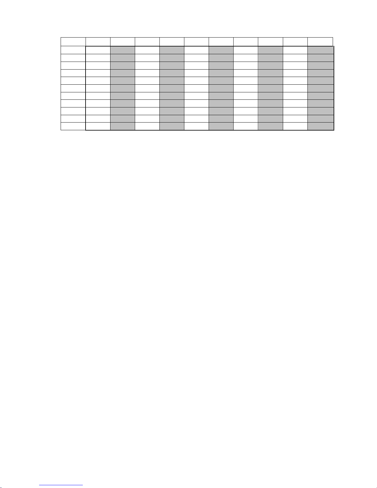
Table A.1 (Continue) mg/dm3
t, °С 0 0,1 0,2 0,3 0,4 0,5 0,6 0,7 0,8 0,9
40 6,41
6,40 6,39 6,38 6,37
6,36 6,35 6,34 6,33
6,32
41 6,31
6,30 6,29 6,28 6,27
6,26 6,25 6,24 6,23
6,22
42 6,21
6,20 6,19 6,19 6,18
6,17 6,16 6,15 6,14
6,13
43 6,12
6,11 6,10 6,09 6,08
6,07 6,06 6,05 6,04
6,04
44 6,03
6,02 6,01 6,00 5,99
5,98 5,97 5,96 5,95
5,94
45 5,93
5,92 5,92 5,91 5,90
5,89 5,88 5,87 5,86
5,85
46 5,84
5,83 5,82 5,82 5,81
5,80 5,79 5,78 5,77
5,76
47 5,75
5,74 5,74 5,73 5,72
5,71 5,70 5,69 5,68
5,67
48 5,66
5,66 5,65 5,64 5,63
5,62 5,61 5,60 5,59
5,59
49 5,58
5,57 5,56 5,55 5,54
5,53 5,52 5,52 5,51
5,50
50 5,49
5,48 5,47 5,47 5,46
5,45 5,44 5,44 5,43
5,42
 Loading...