


V290iA User Guide
Version 1.0

Copyright and Compliance
Copyright Information
Copyright © 2006 Vyyo Inc. All rights reserved.
Vyyo reserves the right to alter all equipment specifications and descriptions in this publication
without prior notice. No part of this publication shall be deemed part of any contract or warranty
unless specifically incorporated by reference into such contract or warranty.
The information herein is merely descriptive in nature, and does not constitute a binding offer for
the sale of the product described herein. Any use of the Vyyo Inc. logo or trademarks is forbidden
without prior written approval from Vyyo Inc.
All trademarks mentioned herein are the property of their respective owners. Vyyo Inc.’s
trademarks include, but are not limited to, “Vyyo” and “Wireless liberty for all.”
FCC Compliance Information
NOTE: This equipment is authorized under FCC ID PBJ290-IA to operate in the A block of the
Upper 700 MHz Guard Band pursuant to Part 27 of the FCC’s rules.
In addition, this equipment has been tested and found to comply with the limits for a Class B
digital device pursuant to Part 15 of the FCC’s rules.
These limits are designed to provide reasonable protection against harmful interference in a
residential installation. This equipment generated, uses, and can radiate radio frequency
energy, and if not installed and used in accordance with the instructions, may cause harmful
interference to radio communications. However, there is no guarantee that interference will not
occur in a particular installation.
If this equipment does cause harmful interference to radio or television reception, which can be
determined by turning the equipment on and off, the user is encouraged to try to correct the
interference by one or more of the following measures:
Reorient or relocate the antenna.
Increase the distance between the equipment and the receiver.
Connect the equipment into an outlet on a circuit different from that to which the
receiver was connected.
Consult the dealer or an experienced radio/TV technician for assistance.
NOTE: This equipment is authorized under FCC ID No. LDK102052P and complies with 15C.
User installation is prohibited. The antenna(s) used for this transmitter must be installed to
provide a separation distance of at least 20 cm from all persons and must not be co-located or
operating in conjunction with any other antenna or transmitter. End-users and installers must be
provided with antenna installation instructions and transmitter operating conditions for satisfying
RF exposure compliance.
Warning! Changes or modifications to this equipment not expressly approved by Vyyo
Inc. could void the user’s authority to operate the equipment.
This product was tested with shielded coaxial cable (not provided by Vyyo) and
Category 5 Ethernet cable (optional) equipped with a shielded RJ-45 connector.
These types of cables must be used with the unit to ensure compliance.


Table of Contents
About This Guide ......................................................................................1
Intended Audience.............................................................................................1
Document Objectives.........................................................................................1
Document Conventions......................................................................................1
How This Guide is Organized ............................................................................ 2
Related Documentation .....................................................................................3
Obtaining Documentation ..................................................................................3
Documentation Feedback ..................................................................................3
List of Abbreviations...........................................................................................4
Chapter 1 Overview ............................................................................................7
V290iA and the Vyyo BWA System ...................................................................7
Chapter 2 Physical and Functional Description..............................................9
V290iA Basic Description...................................................................................9
Interfaces ......................................................................................................... 10
Housing............................................................................................................ 11
Heating and Cooling ........................................................................................11
Power............................................................................................................... 12
Modem V290iA Initialization Process...............................................................12
Chapter 3 Installing the V290iA.......................................................................15
Prerequisites to Installation..............................................................................15
Verifying Package Contents.............................................................................16
Mounting the V290iA........................................................................................16
Wall Mounting .............................................................................................17
Pole Mounting .............................................................................................17
Shelf Mounting ............................................................................................18
V290iA User Guide i

1 Overview
Cable Connections...........................................................................................18
Initial Operation................................................................................................ 19
Chapter 4 Configuring the V290iA ..................................................................21
Configuring V290iA Components.....................................................................21
Configuring the Cisco Router ...................................................................... 22
V290iA Cisco 3200 Default Configuration...................................................22
SCADA Traffic Configuration.......................................................................23
Chapter 5 Maintenance ....................................................................................29
Interface Panel LEDs.......................................................................................29
WiFi LEDs Operation...................................................................................30
Upgrading Software .........................................................................................31
Upgrading the V284 Software ..................................................................... 31
Chapter 6 Troubleshooting..............................................................................33
Appendix A V290iA Technical Specifications ...................................................35
V290iA General Characteristics.......................................................................35
UHF Radio Characteristics ..............................................................................36
Appendix B Antennas Technical Specifications...............................................37
Shrouded Yagi Antenna................................................................................... 37
Yagi Electrical and Mechanical Specifications ............................................ 37
Mounting Options ........................................................................................ 38
Flat Panel Subscriber Antenna ........................................................................ 39
Flat Panel – Electrical and Mechanical Specifications ................................ 39
Flat Panel – Environmental Specifications ..................................................40
Appendix C Power Cable Specifications ...........................................................41
Power Connector Requirements......................................................................41
External Cables Requirements ........................................................................41
Internal Connectors Description..................................................................42
Appendix D UHF Antenna Cable Specifications ...............................................45
Appendix E Serial Cable Specifications ............................................................47
EIA/TIA−232 Speed and Distance Limitations.................................................47

Chapter 0 Overview
Appendix F Ethernet Cable Specifications .......................................................49
Ethernet (AUI) Port Pinout (DB−15)................................................................. 49
Ethernet Version 2 and IEEE 802.3 Physical Characteristics..........................50
Ethernet Coaxial−type Connection Limits for 10−Mbps Transmission ............50
Appendix G FCC Declaration of Conformity .....................................................51
V290iA User Guide iii

About This Guide
The V290iA User Guide is part of the documentation package for the Vyyo wireless
access system. The guide describes the V290iA device, and how to install, configure
and maintain the V290iA.
; For instructions on installing the antenna, refer to the appropriate guide. An antenna
must be installed by a professional following all safety precautions.
Intended Audience
This guide is intended for service personnel required to install, configure or maintain the
V290iA.
Document Objectives
This guide is designed to be used as a tool in the initial installation and periodic
maintenance of the V290iA. It contains information on how to perform the following
tasks:
Installing the V290iA
Configuring the V290iA
Maintaining the V290iA
Troubleshooting the V290iA
Document Conventions
The following icons appear throughout this guide:
; Note: This is a note. It provides additional information on the current topic.
Warning: This is a warning. It contains cautionary information on the current topic.
Tip: This is a tip. It provides time saving information to the reader.
V290iA User Guide 1

Overview
How This Guide is Organized
This guide is organized into the following chapters and appendices:
Chapter 1: Overview
This chapter provides an overview of the V290iA and the Vyyo wireless access system.
Chapter 2: Physical and Functional Description
This chapter includes a physical and functional description of the V290iA and its
components, as well as an overview of the process of modem initialization.
Chapter 3: Installing the V290iA
This chapter details installation prerequisites, explains the various mounting options
and how to connect the cables, and describes initial operation.
Chapter 4: Configuring the V290iA
This chapter explains how to configure the V290iA components.
Chapter 5: Maintaining the V290iA
This chapter details the normal operation of the V290iA LEDs and describes how to
upgrade the V290iA software.
Chapter 6: Troubleshooting
This chapter provides troubleshooting information to help solve common problems.
Appendix A: V290iA Technical Specifications
This appendix provides technical specifications for the V290iA.
Appendix B: Antennas Technical Specifications
This appendix provides technical specifications for the two optional antennas.
Appendix C: Power Cable Specifications
This appendix provides technical specifications for the power cable.
Appendix D: Antenna Cable Specifications
This appendix provides technical specifications for the antenna cable.
2 V290iA User Guide

Overview
Appendix E: Serial Cable Specifications
This appendix provides technical specifications for the two optional serial cables.
Appendix F: Ethernet Cable Specifications
This appendix provides technical specifications for the Ethernet cable.
Appendix G: FCC Declaration of Conformity
This appendix displays Vyyo’s FCC Declaration of Conformity.
Related Documentation
For information on other Vyyo wireless system topics, see the following guides:
NMS User Guide
Base Station User Guide
V290iA Quick Reference Guide
Obtaining Documentation
To obtain additional documentation, please contact info@vyyo.com.
Documentation Feedback
We welcome your comments about this guide. Please send comments to:
Address: 6625 The Corners Parkway, Suite 210, Norcross, GA 30092
Tel: 678.282.8000
Fax: 770.447.2405
Email address: info@vyyo.com
Please include in the comment the name and version number of the guide.
V290iA User Guide 3

Overview
List of Abbreviations
Following is a list of the abbreviations used in the guide.
Abbreviation Meaning
BPI Baseline Privacy Interface
BSR Base Station Rack
BTS Base Stations
BW bandwidth
CLI Command Line Interface
WMTS Wireless Modem Termination System
CPE Customer Premises Equipment
CRC Cyclic Redundancy Check
dB Decibels
dBmV Decibel-Millivolt
DES Digital Encryption Standard
DHCP Dynamic Host Configuration Protocol
DOCSIS Data-Over-Cable Service Interface Specifications
DS Downstream
DSCP Differentiated Services Code Point
FDD Frequency Division Duplexing
FEC Forward Error Correction
FTP File Transfer Protocol
GHz Gigahertz
ICMP Internet Control Message Protocol
IEEE Institute of Electrical and Electronic Engineers
IETF Internet Engineering Task Force
IGMP Internet Group Management Protocol
IP Internet Protocol
ISO International Standards Organization
ITU International Telecommunications Union
ITU-T Telecommunication Standardization Sector of the
4 V290iA User Guide
International Telecommunication Union

Overview
Abbreviation Meaning
Kbps Kilobits per second
kHz Kilohertz
LAN Local Area Network
LOS Line of Sight
LLC Logical Link Control procedure
MAC Media Access Control
Mbps Megabits per second
MHz Megahertz
MIB Management Information Base
MPEG Moving Picture Experts Group
Ms Millisecond
MTU Maximum Transmission Unit
NLOS Non Line of Sight
NMS Network Management System
Ns Nanosecond
PHY Physical Layer
PPP Point-to-Point Protocol
QAM Quadrature Amplitude Modulation
QoS Quality of Service
QPSK Quadrature Phase-Shift Keying
RF Radio Frequency
RFC Request For Comments
SNAP Subnetwork Access Protocol
SNMP Simple Network Management Protocol
SNR Signal-to-Noise Ratio
TCP Transmission Control Protocol
TFTP Trivial File-Transfer Protocol
US Upstream
V290iA User Guide 5


1 Overview
The V290iA is a Customer Premises Equipment (CPE) device used to provide wireless
communications at remote locations as part of a Vyyo wireless network. The V290iA
provides remote connectivity for SCADA and IP devices.
The V290iA consists of three major components, integrated into a single chassis:
A Vyyo wireless modem, used for communicating over the Vyyo wireless network.
A Cisco 3200-series router, providing IP routing capability for the Vyyo wireless
network and integration into an enterprise network. Ethernet ports provide
connectivity to IP devices located at the CPE site. Serial ports provide connectivity
to SCADA devices.
A manageable Power and Control Card.
The V290iA connects to an external antenna. Two optional antennas are available.
Refer to Appendix B: Antennas Technical Specifications for the antennas’ technical
specifications.
V290iA and the Vyyo BWA System
The V290iA is the CPE component of the Vyyo Broadband Wireless Access (BWA)
system, which resides at the Sub Station. The BWA system is designed to provide endto-end wireless connectivity for SCADA and IP devices, and to interconnect seamlessly
with your enterprise network. The V290iA communicates on the 700MHz wireless band.
The following figure shows the Vyyo BWA network topology:
Error! Not a valid link.
Figure 1: Vyyo BWA Network Topology
V290iA User Guide 7


2 Physical and Functional Description
The V290iA is comprised of a Vyyo V284 RF modem and a Cisco 3200-series router,
integrated into a single housing. This housing is designed for easy mounting on a wall
or pole in the remote location.
V290iA Basic Description
The following is a general block diagram of the V290iA.
Error! Not a valid link.
Figure 2: V290iA General Block Diagram
The V290iA includes the following main components:
V284+A board – a UHF FDD radio modem operating in the 746-777 MHz frequency
range.
Cisco cards – these include the following:
Mobile Access Router Card (MARC) – The routing engine includes the host
processor and memory. It is connected to the V284+A through a Fast Ethernet
interface.
4-Port Fast Ethernet Switch Mobile Interface Card (FESMIC) – The 4-port
FESMIC provides four sets of Fast Ethernet signals. One of these is connected
to the WMIC.
4-Port Serial Mobile Interface Card (SMIC) – The 4-port SMIC provides four
sets of serial signals.
Wireless Mobile Interface Card (WMIC) – The 2.4-GHz WMIC can be
optionally configured as an access point (AP), a root bridge, or a non-root bridge.
The WMIC is connected to a Fast Ethernet port on the FESMIC.
Mobile Router Power Card (MPRC)
Vyyo Power Supply Controller (PSC) card – The PSC provides power
management of the V290iA units: the V284+A, the Cisco cards, and the temperature
control system.
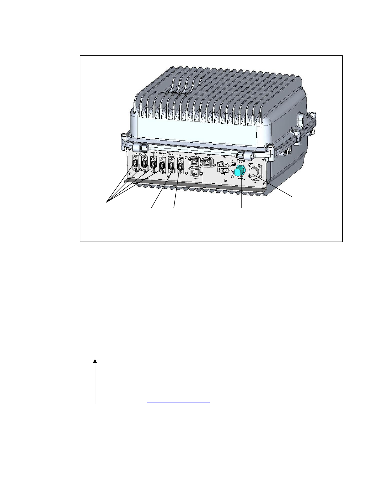
The following is a physical view of the V290iA device:
V290iA User Guide 9
2 Physical and Functional Description
Serial
interfaces
MARC
console
PSC
console
Ethernet
interfaces
UHF Antenna
connector
48 VDC power
connector
Interfaces
The following interfaces are available in the V290iA:
Six DB-9 serial ports – Four serial ports are available to connect serial devices such
as SCADA devices. Two ports serve as console ports: one for the Cisco router
(MARC), and one for the Power and Control Card. Refer to Appendix E: Serial
Cable Specifications for cable specifications.
Three RJ-45 Ethernet ports – The Ethernet ports are available to connect IP devices
such as remote cameras and security devices. Refer to Appendix 0: Ethernet Cable
Specifications for cable specifications.
UHF RF antenna connector – Use for connecting to the Vyyo wireless network.
Refer to Appendix D: UHF Antenna Cable Specifications for cable specifications.
Two WiFi antenna connectors – the Cisco router has wireless routing capabilities to
connect WiFi devices to the enterprise network. For more information on WiFi
antennas, see the Cisco antenna guide
Figure 3: Vyyo V290iA bottom view
.
10 V290iA User Guide

Chapter 2 Physical and Functional Description
WiFi antenna
connectors
Figure 4: Vyyo V290iA top view
Housing
The V290iA is housed in a case designed to be resistant to pressure, moisture, and
extremes in temperature. The V290iA is not intended for field servicing.
The housing is fully sealed, and uses a pressure valve to equalize pressure inside and
outside the housing while holding out water molecules. The housing provides a fully
stable environment with the ability to resist moisture even in full immersion. The
housing is held in place by locking screws to maintain a proper seal.
The Ethernet and Serial interfaces use a rugged design to protect the interface pins.
The interface panel is located on the bottom of the V290iA when it is mounted in the
standard way, and the RF antenna connection is on the top.
A 100° cable is attached to both halves of the housing to permit ease of service for a
field technician. A console port for the Cisco router is available on the interface panel.
Heating and Cooling
In order to maintain the proper working temperature, the V290iA has a temperature
control system included inside the housing. This temperature control system allows the
V290iA to operate in outdoor installations, maintaining a temperature range
between -30° C and 60° C.
V290iA User Guide 11

2 Physical and Functional Description
Power
The V290iA supports an input voltage of 48VDC (36-72 VDC), with 5A input current
protection. The V290iA has a manageable Power and Control Card, providing power to
the different units, such as the Cisco cards, the V284+A card, and the temperature
control system
Modem V290iA Initialization Process
Upon power up, the V290iA performs the following:
1. Scans for a UHF downstream channel – The modem always stores the last set of
parameters it was able to work with. It therefore first tries to reacquire the last
working downstream channel.
2. Synchronizes to the downstream channel – The downstream signal is valid when
the modem has the following:
QAM synchronization.
FEC synchronization.
MPEG frames synchronization.
Recognition of a MAC synchronization message.
3. Receives upstream parameters – The WMTS periodically transmits on the
downstream channel a broadcast information message to all modems on the sector
regarding upstream channels in the sector. The upstream information includes
symbol rate, modulation, FEC, preamble and scrambling.
4. Receives bandwidth allocation MAP – The WMTS periodically transmits on the
downstream channel a broadcast message to all modems on the sector regarding
the upstream bandwidth access opportunities of a coming time interval.
5. Performs ranging and adjustments – The modem synchronizes with the WMTS
on the upstream timing, frequency and transmission power.
6. Establishes IP connectivity – The modem acquires the network setting (IP
address, subnet mask and more) from the DHCP server. The modem entry in the
DHCP server is configured through the Vyyo Web NMS (refer to the NMS User
Guide).
7. Establishes Time of Day – The modem acquires the date and time from a time
server, for proper messaging.
8. Acquires configuration – The modem downloads its configuration file from a TFTP
server. The TFTP file name is provided by the DHCP server, and is configured
through the Vyyo Web NMS (refer to the NMS User Guide). The modem
configuration file includes information about downstream and upstream channels,
available services, service classifiers and priorities, etc.
9. Registers with the WMTS.
12 V290iA User Guide

Chapter 2 Physical and Functional Description
10. The Cisco Router establishes IP connectivity – The router acquires the network
setting (IP address, subnet mask and more) from the DHCP server.
; Note: The description of how the Cisco router establishes IP connectivity, applies
to the V290iA default Cisco setting. The customer may change the Cisco
setting to a fixed IP address, or any other IP addressing method supported
by the Cisco IOS. The Cisco addressing is not managed by the Vyyo NMS,
and should be configured by the system administrator.
V290iA User Guide 13


3 Installing the V290iA
The V290iA is designed to be installed on a wall, pole, or shelf. This section describes
all the steps required for installation.
; For instructions on installing the antenna, refer to the appropriate guide. An antenna
must be installed by a professional following all safety precautions.
Prerequisites to Installation
Before installing the V290iA:
1. Make sure the antenna is installed and adjusted.
2. It is recommended to have a PC available, for connecting to one of the Console
ports.
3. Provision the V290iA in the NMS (refer to the NMS User Guide). You need the
V290iA’s MAC address, which is displayed on the V290iA label, as shown in
Figure 5.
4. Check the installation environment to ensure compliance with the following
requirements:
Operating temperature: -22°F to +158°F, -30°C to +60°C.
Storage temperature: 40°F to +185°F, -40°C to +85°C.
V290iA User Guide 15
Figure 5: V290iA MAC Address

3 Installing the V290iA
Relative humidity: 95% (non-condensing).
Vibration: IEEE 1613, Class V.S.2.
Shock: IEEE 1613, 100 mm.
5. Make sure you have the following cables:
Power cable (for cable specifications, refer to Appendix C: Power Cable
Specifications).
Antenna cable (for cable specifications, refer to Appendix D: UHF Antenna Cable
Specifications).
Serial cable (for cable specifications, refer to Appendix E: Serial Cable
Specifications).
Ethernet cable (for cable specifications, refer to Appendix F: Ethernet Cable
Specifications).
6. Make sure you have the necessary tools.
Verifying Package Contents
Make sure the package contains the following:
One pole mounting bracket.
One main mounting bracket.
Four HEX HD SST 1/4-20 NC x 5/8" screws.
Four SST FLAT-RU #1/4 washers.
Four HEX HD SST 3/8-16 UNC x 3.5" FULL THREAD screws.
Four SST LOCK 1/4 washers.
Four SST LOCK 3/8 washers.
Mounting the V290iA
The V290iA can be mounted on a wall, a pole, or a shelf.
In wall mounting, the interface panel faces down, and the main mounting bracket
faces to the rear.
In pole mounting, pole mounting brackets attach to the main mounting bracket.
In shelf mounting, the main mounting bracket faces forward, and the interface panel
faces to the rear.
The following sections provide detailed instructions for each type of mounting.
16 V290iA User Guide

Chapter 3 Installing the V290iA
Wall Mounting
To mount the V290iA on a wall:
1. Orient the device so that the main mounting bracket (refer to Figure 3) faces the wall
and the interface panel faces down.
2. Attach the device to the wall using the enclosed mounting screws.
3. Attach the interface cables for the SCADA devices at the site to the DB-9 serial
interfaces on the interface panel.
4. Attach the interface cables for any Ethernet-connected devices, such as sensors or
cameras, to the Ethernet ports on the interface panel.
5. Attach the RF antenna to the antenna connectors on the top of the device housing
(assuming the device is oriented properly).
6. Attach the power cable to the power outlet on the interface panel. The device
powers up.
7. Monitor the Modem RF LED on the interface panel to verify that the modem is
functional. For more information on the Modem RF LED, refer to Interface Panel
LEDs on page 29.
Pole Mounting
To mount the V290iA on a pole:
1. Orient the device so the main mounting bracket (refer to Figure 3) faces the wall and
the interface panel faces down.
2. Place the provided pole mounting bracket around the pole at the desired height.
3. Attach the pole mounting bracket to the main mounting bracket of the device using
the enclosed self-locking press nuts.
4. Verify that the device is secure on the pole before proceeding.
5. Attach the interface cables for the SCADA devices at the site to the DB-9 serial
interfaces on the interface panel.
6. Attach the interface cables for any Ethernet-connected devices, such as sensors or
cameras, to the Ethernet ports on the interface panel.
7. Attach the RF antenna to the antenna connectors on the top of the device housing
(assuming the device is oriented properly).
8. Attach the power cable to the power outlet on the interface panel. The device
powers up.
9. Monitor the Modem RF LED on the interface panel to verify that the modem is
functional. For more information on the Modem RF LED, refer to Interface Panel
LEDs on page 29.
V290iA User Guide 17

3 Installing the V290iA
Shelf Mounting
To mount the V290iA on a shelf:
1. Orient the device so the main mounting bracket (refer to Figure 3) faces the front
and the interface panel faces back.
2. Attach the device to the shelf using the enclosed mounting screws.
3. Attach the interface cables for the SCADA devices at the site to the DB-9 serial
interfaces on the interface panel.
4. Attach the interface cables for any Ethernet-connected devices, such as sensors or
cameras, to the Ethernet ports on the interface panel.
5. Attach the RF antenna to the antenna connectors in the front of the device housing
(assuming the device is oriented properly).
6. Attach the power cable to the power outlet on the interface panel. The device
powers up.
7. Monitor the Modem RF LED on the interface panel to verify that the modem is
functional. For more information on the Modem RF LED, refer to Interface Panel
LEDs on page 29.
Cable Connections
The following figure displays the V290iA front panel connectors.
Figure 6: V290iA Front Panel Connectors
Perform the following cable connections (refer to Figure 6):
1. Connect the Flat Panel or Yagi antenna to the V290iA UHF connector.
2. Optionally connect the WiFi antenna to the V290iA’s WiFi connector, located on the
top of the V290iA chassis.
3. Optionally connect serial devices (e.g., SCADA) to the DB-9 serial ports: SER0,
SER1, SER2, and SER3.
4. Optionally connect IP devices (e.g., remote cameras) to the Ethernet ports: RE0X,
FE1X, and FE2X.
5. Connect the Power cable to the power connector, as follows:
18 V290iA User Guide

Chapter 3 Installing the V290iA
a. Before connecting the Power cable, verify that the voltage is between
36 - 72Vdc.
b. Before connecting the Power cable, if an external power switch exists, turn it
OFF.
c. Connect the Power cable.
Initial Operation
The V290iA starts operating as soon as power is connected. If you turned off the
external power switch prior to connecting the power cable, turn it ON.
The front panel LEDs behave as described in Interface Panel LEDs on page 29. If the
behavior of the LEDs deviates from standard, refer to Troubleshooting on page 33.
V290iA User Guide 19


4 Configuring the V290iA
The V290iA comes with a standard configuration on delivery, and requires minimal, if
any, additional configuration to operate normally. The V290iA uses the embedded
Cisco 3200-series router to enable IP routing and bridging functionality, and can be
configured to provide additional services beyond those provided by the standard
configuration. The Vyyo V284 modem is configured to work as delivered. For advanced
modifications to modem settings, refer to the Vyyo NMS User Guide.
The standard configuration includes default IP address and Netmask information for the
V284 modem and the Cisco router. The default IP information is as follows:
Table 1: Default IP Settings
Parameter Value
Modem IP Address 192.168.100.1
Modem Netmask 255.255.255.0
Router Ethernet IP Address 192.168.100.10
Router Ethernet Netmask 255.255.255.240
Router VLAN Loopback IP 10.0.0.254
Router VLAN Loopback
Netmask
255.255.255.0
; The Modem IP settings are used only for local management. The modem passes no IP
information over the network. The Modem IP settings cannot be changed.
Configuring V290iA Components
The V290iA contains two configurable components:
V284 Modem – All V284 configuration is performed using the NMS (refer to the
NMS User Guide).
Cisco Router – detailed in the following section.
V290iA User Guide 21

4 Configuring the V290iA
Configuring the Cisco Router
This section describes the Cisco default configuration, and an example of SCADA traffic
configuration.
V290iA Cisco 3200 Default Configuration
The V290iA Cisco 3200 component default configuration enables the following
operations:
Local Telnet connectivity to the UHF modem via the FESMIC LAN interfaces for
management and monitoring purpose.
Local Telnet connectivity to the WMIC card via the FESMIC LAN interfaces for
management purpose.
WiFi client’s connectivity.
Serial ports connectivity by Telnet tunneling. In this configuration, data can be
received or transmitted using Telnet to the router IP address with the relevant TCP
port.
The default configuration disables all the dynamic routing protocols and the Cisco
discovery protocol.
Default Configuration Parameters
MARC IP address via the RF (UHF) link is acquired by DHCP and is
192.168.100.10 when the UHF modem is not registered to the WMTS
MARC IP address via the FESMIC LAN interface is 10.0.0.30
WMIC IP address is 10.0.0.1
Default Configuration CLI Commands
The following displays the V290iA Cisco 3200 default values’ running configuration.
service timestamps debug datetime msec
service timestamps log datetime msec
no service password-encryption
no service config
!
hostname Router
!
boot-start-marker
boot-end-marker
!
!
no aaa new-model
!
interface Serial1/3
physical-layer async
no ip address
!
interface FastEthernet2/0
!
interface FastEthernet2/1
!
interface FastEthernet2/2
!
interface FastEthernet2/3
!
interface Vlan1
22 V290iA User Guide

Chapter 4 Configuring the V290iA
resource policy
!
ip subnet-zero
ip cef
!
!
no ip dhcp use vrf connected
!
!
no ip ips deny-action ips-interface
!
!
!
interface FastEthernet0/0
ip address dhcp
no shutdown
duplex auto
speed auto
!
interface Serial1/0
physical-layer async
no ip address
!
interface Serial1/1
physical-layer async
no ip address
!
interface Serial1/2
physical-layer async
no ip address
!
ip address 10.0.0.30 255.255.255.224
no shutdown
!
ip classless
!
!
no ip http server
no ip http secure-server
!
!
!
control-plane
!
!
line con 0
exec-timeout 0 0
stopbits 1
line 1 4
exec-timeout 0 0
session-limit 1
modem InOut
no exec
transport input telnet
transport output telnet
escape-character NONE
telnet break-on-ip
stopbits 1
line aux 0
line vty 0 4
password vyyo
login
!
end
Router#
SCADA Traffic Configuration
The V290iA optionally interfaces with asynchronous SCADA devices via serial ports
Ser0 – Ser3. This section illustrates how to transmit SCADA traffic using TCP
encapsulation over Telnet tunneling.
Telnet Tunneling
Telnet Tunneling protocol uses the TCP protocol to deliver raw data between serial
ports. In this method, the router directs the Telnet packets to the desired serial port
according to the destination TCP port of the Telnet connection (4001 is the default port
for Serial Port 1 Raw Data, 4002 for port 2, and so on). The SCADA master is the
V290iA User Guide 23

4 Configuring the V290iA
Telnet caller and the SCADA device is the called. Once the caller receives serial data, it
initiates a permanent TCP connection.
Telnet Tunneling Configuration
This configuration uses the following network setup.
Caller Side Configuration
The following displays the caller-side configuration.
!
version 12.4
service tcp-keepalives-out
service timestamps debug datetime msec
service timestamps log datetime msec
no service password-encryption
no service config
!
hostname Router
!
boot-start-marker
boot-end-marker
!
!
no aaa new-model
!
resource policy
!
ip subnet-zero
ip cef
!
!
no ip dhcp use vrf connected
!
Figure 7: SCADA Traffic Tunneling
!
ip host SER1 4001 10.1.1.2
ip host SER2 4002 10.1.1.2
ip host SER3 4003 10.1.1.2
ip host SER4 4004 10.1.1.2
no ip ips deny-action ips-interface
!
!
!
!
no spanning-tree vlan 1
!
!
!
interface FastEthernet0/0
ip address 10.1.1.1 255.255.255.0
no shutdown
duplex auto
speed auto
!
interface Serial1/0
physical-layer async
no ip address
24 V290iA User Guide

Chapter 4 Configuring the V290iA
!
interface Serial1/1
physical-layer async
no ip address
!
interface Serial1/2
physical-layer async
no ip address
!
interface Serial1/3
physical-layer async
no ip address
!
interface FastEthernet2/0
!
interface FastEthernet2/1
!
interface FastEthernet2/2
!
interface FastEthernet2/3
!
interface Vlan1
ip address 10.0.0.30 255.255.255.224
no shutdown
!
ip classless
ip route 0.0.0.0 0.0.0.0 FastEthernet0/0
!
!
no ip http server
no ip http secure-server
!
no cdp run
busy-message SER1 ^C ^C
busy-message SER2 ^C ^C
busy-message SER3 ^C ^C
busy-message SER4 ^C ^C
!
!
control-plane
!
!
line con 0
stopbits 1
flowcontrol NONE
line 1
no motd-banner
no exec-banner
exec-timeout 0 0
session-timeout 0 0
no flush-at-activation
no vacant-message
no modem inout
autocommand telnet SER1 /stream
no activation-character
special-character-bits 8
escape-character NONE
autohangup
stopbits 1
exec
no autobaud
speed 9600
flowcontrol NONE
transport input NONE
line 2
no motd-banner
no exec-banner
exec-timeout 0 0
session-timeout 0 0
no flush-at-activation
no vacant-message
no modem inout
autocommand telnet SER2 /stream
no activation-character
special-character-bits 8
escape-character NONE
autohangup
stopbits 1
exec
no autobaud
speed 9600
flowcontrol NONE
transport input NONE
line 3
no motd-banner
no exec-banner
exec-timeout 0 0
session-timeout 0 0
no flush-at-activation
no vacant-message
no modem inout
V290iA User Guide 25

4 Configuring the V290iA
autocommand telnet SER3 /stream
no activation-character
special-character-bits 8
escape-character NONE
autohangup
stopbits 1
exec
no autobaud
speed 9600
flowcontrol NONE
transport input NONE
line 4
no motd-banner
no exec-banner
exec-timeout 0 0
session-timeout 0 0
no flush-at-activation
no vacant-message
no modem inout
autocommand telnet SER4 /stream
no activation-character
special-character-bits 8
escape-character NONE
autohangup
stopbits 1
exec
no autobaud
speed 9600
flowcontrol NONE
transport input NONE
line aux 0
line vty 0 4
!
end
V290iA (Called side) Configuration
The following displays the called-side configuration.
Current configuration : 1719 bytes
!
version 12.4
service tcp-keepalives-in
no banner incoming
service timestamps debug datetime msec
service timestamps log datetime msec
no service password-encryption
no service config
!
hostname Router
!
boot-start-marker
boot-end-marker
!
!
no aaa new-model
!
resource policy
!
ip subnet-zero
ip cef
!
!
no ip dhcp use vrf connected
!
!
no ip ips deny-action ips-interface
!
!
no spanning-tree vlan 1
!
!
!
interface FastEthernet0/0
ip address 10.1.1.2 255.255.255.0
no shutdown
duplex auto
speed auto
!
interface Serial1/0
physical-layer async
no ip address
!
interface Serial1/1
physical-layer async
no ip address
!
26 V290iA User Guide

Chapter 4 Configuring the V290iA
interface Serial1/2
physical-layer async
no ip address
!
interface Serial1/3
physical-layer async
no ip address
!
interface FastEthernet2/0
!
interface FastEthernet2/1
!
interface FastEthernet2/2
!
interface FastEthernet2/3
!
interface Vlan1
ip address 10.0.0.62 255.255.255.224
no shutdown
!
ip classless
ip route 0.0.0.0 0.0.0.0 FastEthernet0/0
!
!
no ip http server
no ip http secure-server
!
no cdp run
!
!
control-plane
!
!
line con 0
stopbits 1
line 1 4
no exec-banner
no vacant-message
modem DTR-active
special-character-bits 8
no autobaud
speed 9600
no exec
flowcontrol NONE
transport input telnet
escape-character NONE
dispatch-character 5
stopbits 1
line aux 0
line vty 0 4
!
end
Router#
V290iA User Guide 27


5 Maintenance
The V290iA is designed for high reliability and requires only limited maintenance. This
chapter describes the behavior of the V290iA LEDs during normal operation. In the
event of device functionality issues, refer to Troubleshooting on page 33.
Interface Panel LEDs
The following figure shows the LEDs on the V290iA’s interface panel. These LEDs
provide performance indications for the V290iA.
Figure 8: V290iA Front Panel LEDs
The following table describes the LEDs and their functions.
Table 2: V290iA LEDs
LED Function
Power Status
Router OK
WiFi Ethernet (E)
V290iA User Guide 29
• Amber when power is supplied to both the V284 and the Cisco
router.
• Green when power is supplied only to the V284.
• Red when power is supplied only to the Cisco router.
• Blinks green when a power fault is detected in the V284.
• Blinks red when a power fault is detected in the Cisco router.
• Blinks amber when a power fault is detected in both the V284 and
the Cisco router.
Blinks green during router boot-up sequence. Green when the router is
operational.
• Blinks green when transmitting/receiving Ethernet packets.
• Green when Ethernet link operational.

5 Maintenance
LED Function
WiFi RF (RF)
WiFi Status (S)
Modem
Ethernet (E)
Modem Status (S)
Modem RF (RF)
• Blinks green when transmitting/receiving radio packets.
• Green when RF link is operational.
• Blinks green when no devices are associated with the WiFi
interface.
• Green when at least one device is associated with the WiFi
interface.
• On when the Ethernet link is operational.
• Off when the Ethernet link is not operational.
• Flashing when data is transmitting/receiving.
• On when the V284 is registered.
• Off when the V284 is not registered.
When Status LED is Off:
• On when the downstream link is operational.
• Off when the modem has not yet begun downstream
acquisition, the downstream link is idle, or there is a problem
with data reception.
• Flashing when the downstream link is being acquired.
When Status LED is On:
• Flashing when data is transferring in either in the Upstream or
Downstream direction.
Link/Act (for each
Serial port)
Link (for each
Ethernet port)
Act (for each
Ethernet port)
Green when the serial port is operational. Blinks red when packets are
transmitted or received.
Green when the Ethernet port is connected to a device.
Blinks green when packets are transmitted or received.
WiFi LEDs Operation
As shown in Figure 8, the V290iA front panel includes three WiFi LEDs: Ethernet (E),
Status (S), and Radio (RF). These LEDs are used in combination to determine overall
V290iA device status.
If any of the WiFi LEDs is Red or Amber (steady or blinking) this indicates an
initialization state, warning or a failure state. Refer to Troubleshooting on page 33 for
details.
30 V290iA User Guide

Chapter 5 Maintenance
Upgrading Software
The V290iA has two upgradeable software elements:
The V284 UHF modem. The software upgrade is detailed below.
The Cisco IOS software. The software upgrade is performed by Cisco tools. Refer to
the Cisco 3200 release notes:
http://www.cisco.com/univercd/cc/td/doc/product/access/mar_3200/mar_rlsn/index.htm
Upgrading the V284 Software
To upgrade the V284:
1. Ensure that the latest release of the V290iA software is loaded on a laptop which is
running a TFTF server (pumpkin).
2. Make sure the TFTP server (pumpkin) is activated, and set to permit access to the
directory in which the software package is located.
3. Connect a serial cable from the serial port on the laptop to the Modem Console port
on the interface panel.
4. Open terminal emulation software on the laptop and verify the connection with the
V290iA.
5. Type cd d to go to the docsis directory.
6. Type docsis_ctl.
7. Type dload <ipaddress> <image_name>, where:
ipaddress is the IP address of the laptop running the TFTP server.
image_name is the filename of the software package.
The download process takes a few moments. When download is complete, the V284
resets itself.
V290iA User Guide 31


6 Troubleshooting
{?TBD}
V290iA User Guide 33


A V290iA Technical Specifications
This appendix lists the V290iA technical specifications.
When installing the V290iA, you must ensure that the physical environment and RF
configuration meet these requirements. For example, the pole must be able to support the
device’s weight, and the antenna must be compatible with the listed frequency ranges.
V290iA General Characteristics
Parameter Specification
Physical
Height 13.4', 340 mm
Width 12.2', 310 mm
Depth 7.1', 180 mm
Max. Weight 26.5 lbs, 12 Kg.
Environmental
Operating temperature -22°F to +158°F, 30°C to +60°C
Storage temperature -40°F to +185°F, -40°C to +85°C
Relative humidity 95% (non-condensing)
Vibration IEEE 1613, Class V.S.2
Shock IEEE 1613, 100 mm
Ingress Protection IP40 (1 mm objects)
Regulations
IEEE std-1613-2003 compliance
FCC C.F.R 47 - Part 15B and part 27
FCC C.F.R 47 - part 27
Power
Power supply range 36 to 72 VDC
Power Polarity ±
V290iA User Guide 35
Rated voltage 48V
Maximum consumption 125W

A V290iA Technical Specifications
UHF Radio Characteristics
Parameter Specification
Downstream
Frequency 746-747 MHz
Channel bandwidth 330 KHz
Modulations 64QAM 16QAM QPSK
SNR for BER < 10E6 24 dB 19 dB 13 dB
Minimum signal level -87 dBm
Maximal signal level -49 dBm
Frequency tolerance ± 50 KHz
Adjacent channels for BER < 10E6 10 dB
FEC ITU-T J.83 Reed Solomon/Trellis
Upstream
Frequency 776-777 MHz
Channel bandwidth 325 KHz
Modulation 16QAM or QPSK
Transmit level -17 to +27 dBm
Decoder
PA output power P1dB 32 dBm
FEC Reed Solomon, with optional
training
36 V290iA User Guide

B Antennas Technical Specifications
This appendix lists the technical specifications of the two optional UHF antennas.
Shrouded Yagi Antenna
Following are the specifications for the 4RF0054-A model of the 746 -777 MHz
shrouded Yagi antenna.
Yagi Electrical and Mechanical Specifications
Parameter Specification
Frequency range 746-777 MHz
Input Impedance 50 Ohms
Return Loss >15 dB
Front to Back Ratio 20 dB
Maximum Input Power 250 Watts
Polarization Vertical & Horizontal
Forward Gain 11.5dBd
3 dB Beamwidth E Plane 37º, H Plane 41º
Connection N socket
Radiator ptfe Printed Circuit
Elements Aluminium Alloy
Radiator Feed Sucoform 141
Antenna Base Sandcast Aluminium Alloy Grade LM25
Radome Fire retardant Polyurethane Moulding
Fasteners Stainless Steel Grade A2-70
Lightning protection Direct Grounded
Mounting Brackets Hot Dip Galvanized Steel to suit 38 - 60mm. dia.
V290iA User Guide 37

B Antennas Technical Specifications
Parameter Specification
Typical Weight 6 kg (inc. clamp)
Typical Length 1.3 m
Typical Wind loading @ 45m/s 285N, with 1/2” radial ice 306N
Survival Wind Speed 300km/h with 1/2” radial ice
Operational Temperature Range -50ºC to +80ºC
Mounting Options
Figure 9: Mounting for Vertical Polarization of the Yagi Antenna
Figure 10: Mounting for Horizontal Polarization of the Yagi Antenna
Error! Not a valid link.
Error! Not a valid link.
38 V290iA User Guide

B Antennas Technical Specifications
Flat Panel Subscriber Antenna
Following are the specifications for the 746-777 MHz, 9.5 dBi flat panel subscriber
antenna.
Flat Panel – Electrical and Mechanical Specifications
Parameter Specification
Regulatory Compliance RoHS, CE 0682
Electrical
Frequency range 746-777 MHz
Gain 9.5 dBi (min)
VSWR 2 : 1 (max)
S dB beamwidth AZ: 43º(typ)
Polarization Linear (Vertical or Horizontal)
Cross polarization AZ: -26 dB (max)
F/B ration -25 dB (max)
Input impedance 50 (ohm)
Input power 6 W (max)
Lightning protection DC Grounded
Mechanical
Dimensions (L x W x D) 450 x 450 x 30 mm (max)
EL: 55º(typ)
EL: -26 dB (max)
Weight 3 Kg (max)
Connector N type Female
Radome Plastic
Base plate Aluminum with chemical conversion coating
Outline drawing
Mounting Kit
V290iA User Guide 39

B Antennas Technical Specifications
Flat Panel – Environmental Specifications
Test Standard Duration Temperature Notes
Low temperature IEC 68-2-1 72 h -55ºC –
High temperature IEC 68-2-2 72 h +71ºC –
Temp. cycling IEC 68-2-14 1 h -45ºC + 70ºC 3 Cycles
Vibration IEC 60721-3-4 30 min/axis –
Shock Mechanical IEC 60721-3-4 – – 4M5
Humidity
Water Tightness IEC 529 – – IP63
Solar Radiation ASTAM G53 1000 h – –
Flammability UL 94 – – Class HB
Salt Spray IEC 68-2-11 Ka 500 h – –
Ice and Snow – – –
Wind Speed Survival
Operation
Wind Load (Survival):
Front Thrust
Side Thrust
ESTI EN300-2-4
T4.1 E
– – –
–
–
144 h – 95%
–
–
–
Random
4M5
25 mm
Radial
220 Km/h
160 Km/h
39.6 kg
4.3 kg
40 V290iA User Guide

C Power Cable Specifications
This appendix lists the technical specifications of the power cable.
Power Connector Requirements
The following items are required for the V290iA power inlet matching connector:
Cable – CABLE SHIELDED 4 X 22AWG
Plug sealed – Manufactured by Tyco, MFG: 796094-2.
Pin – Sock pins 15u gold 16-18awg, manufactured by Tyco, MFG: 66101-3.
Boot #11 – Manufactured by Tyco, MFG: 207489-1.
This connector is same as the one used for the Cisco 3230.
External Cables Requirements
Use cables suitable for the environmental required specification.
Do not exceed the allowed cable length according to the common STD (Serial and
Ethernet).
Use the pin out description (refer to Internal Connectors Description below) to
prepare the proper cable wiring according to the specific SCADA device or
communication equipment you intend to attach to the V290iA.
V290iA User Guide 41

C Power Cable Specifications
Internal Connectors Description
Item
1
Item
2
Item
3
Item
4
V290i
Name
SER 0
to
SER3
V290i
Name
PSC
console
V290i
Name
MARC
console
V290i
Name
FE0X to
FE2X
Connector
Description
Connector D-
Type 9pins
Male
Connector
Description
Connector D-
Type 9pins
Female
Connector
Description
Connector D-
Type 9pins
Female
Connector
Description
Connector RJ45
Female
Pin1 = DCD
Pin2 = RxD
Pin3 = TxD
Pin4 = DTR
Pin5 = GND
Pin6 = DSR
Pin7 = RTS
Pin8 = CTS
Pin9 = NC
Pin2 = TxD
Pin3 = RxD
Pin5 = GND
Pin1,4,6,7,8,9=NC
Pin1,9 = NC
Pin2 = TxD out
Pin3 = RxD in
Pin4 = DSR in
Pin5 = GND
Pin6 = DTR out
Pin7 = CTS in
Pin8 = RTS out
Pin1 = RxPO
Pin2 = RxNO
Pin3 = TxPO
Pin4 & 5 = TxC
Pin6 = TxNO
Pin7 & 8= RxC
Pin Number
Pin Number
Pin Number
Pin Number
42 V290iA User Guide

C Power Cable Specifications
Item
5
V290i
Name
UHF
antenna
Connector
Description
Connector N-
Type female 50
ohm
Pin Number
Standard
Item
6
V290i
Name
DC
Input
Connector
Description
Circular plastic
connector 4
pins male
Pin Number
Pin1 = Negative
Pin2 = Positive
Pin3 = Negative
Pin4 = Positive
V290iA User Guide 43


D UHF Antenna Cable Specifications
This appendix lists the technical specifications of the antenna cable. {?TBD}
V290iA User Guide 45


E Serial Cable Specifications
This appendix lists the technical specifications of the EIA/TIA−232 serial cables. Two
optional serial cables can be used: CAB−232MT or CAB−232FC.
EIA/TIA−232 Speed and Distance Limitations
As with all signaling systems, EIA/TIA−232 signals can travel a limited distance at any
given bit rate; generally, the slower the data rate, the greater the distance. The table
below gives the EIA/TIA−232 speed and distance limitations.
Data Rate (Baud) Distance (Feet) Distance (Meters)
2400 200 60
4800 100 30
9600 50 15
19200 50 15
38400 50 15
57600 25 7.6
115200 12 3.7
V290iA User Guide 47


F Ethernet Cable Specifications
This appendix lists the technical specifications of the Ethernet cable.
Ethernet (AUI) Port Pinout (DB−15)
The table below lists the different pins and their appropriate signals.
Pin1 Ethernet Circuit Signal
3 DO−A Data Out Circuit A
10 DO−B Data Out Circuit B
11 DO−S Data Out Circuit Shield
5 DI−A Data In Circuit A
12 DI−B Data In Circuit B
4 DI−S Data In Circuit Shield
2 CI−A Control In Circuit A
9 CI−B Control In Circuit B
1 CI−S Control In Circuit Shield
6 VC Voltage Common
13 VP Voltage Plus
14 VS
Shell PG Protective Ground
1
Any pin not referenced is not connected.
Voltage Shield (L25
and M25)
V290iA User Guide 49

F Ethernet Cable Specifications
Ethernet Version 2 and IEEE 802.3 Physical
Characteristics
The table below lists the Ethernet Version 2 and IEEE 802.3 physical characteristics of
the Ethernet cable.
IEEE 802.3 Ethernet
10Base5 10Base2 10BaseT
Data rate (Mbps) 10 10 10 10
Signaling method Baseband Baseband Baseband Baseband
Maximum
segment length
(in meters)
Media
Topology Bus Bus Bus Star
500 500 185
50−ohm coax
(thick)
50−ohm coax
(thick)
50−ohm coax
(thin)
100 (Unshielded
twisted pair
−UTP)
UTP
Ethernet Coaxial−type Connection Limits for
10−Mbps Transmission
The following table lists the Ethernet coaxial−type connection limits for 10−Mbps
transmission.
Parameter 10Base5 10Base2
Cable diameter 1 cm (0.4 in) 0.6 cm (0.25in)
Maximum segment
length
Maximum network
length (with four
repeaters)
500 m (1640ft.) 152 m (500ft.)
2500 m (8200ft.) 762 m (2500ft.)
Maximum
connections (taps
per segment)
Minimum
connection (tap)
spacing
50 V290iA User Guide
100 30
2.5 m (8.2 ft.) 0.5 m (1.64ft.)
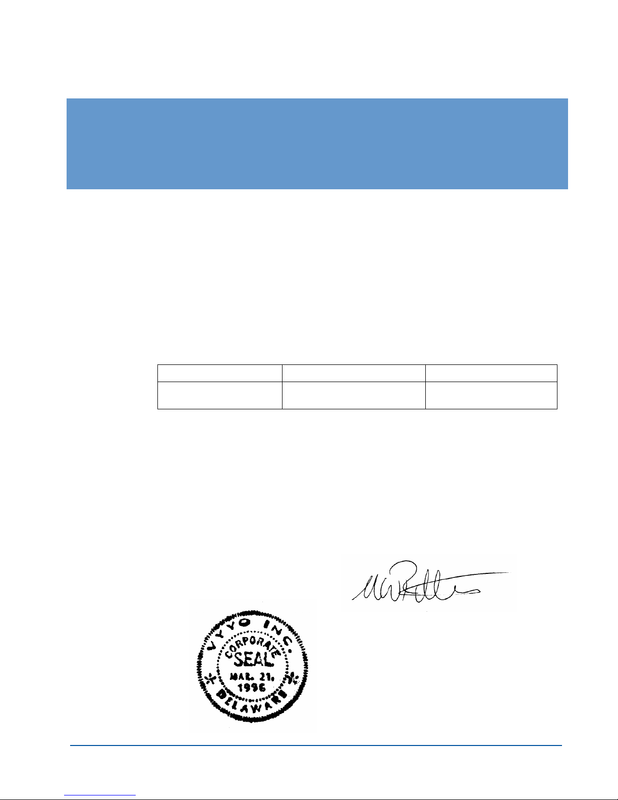
G FCC Declaration of Conformity
We, the undersigned,
Company: VYYO Inc.
Address: 4015 Miranda Avenue, Palo Alto, Ca.
Country: USA
Telephone number: 001-650-3194037
Fax number: 001-650-3194066
Are the Responsible Party for this Declaration, certify and declare under our sole responsibility that
the following equipment:
Brand Type Product description
VYYO V290iA UHF INDUSTRIAL MODEM
Complies with Part 15 of the FCC Rules. Operation is subject to the following two conditions:
(1) this device may not cause harmful interference, and (2) this device must accept any interference
received, including interference that may cause undesired operation.
Drawn up at:
VYYO Inc
4015 Miranda Avenue
Palo Alto, Ca.
USA
VYYO Inc.
WITH WiFi ACCESS POINT
On May 8, 2006
Dr. Mike Ritter
VP. Marketing
V290iA User Guide 51
 Loading...